JP5259372B2 - Steel pipe pile base - Google Patents
Steel pipe pile base Download PDFInfo
- Publication number
- JP5259372B2 JP5259372B2 JP2008322972A JP2008322972A JP5259372B2 JP 5259372 B2 JP5259372 B2 JP 5259372B2 JP 2008322972 A JP2008322972 A JP 2008322972A JP 2008322972 A JP2008322972 A JP 2008322972A JP 5259372 B2 JP5259372 B2 JP 5259372B2
- Authority
- JP
- Japan
- Prior art keywords
- steel pipe
- pipe pile
- pedestal
- base
- end surface
- Prior art date
- Legal status (The legal status is an assumption and is not a legal conclusion. Google has not performed a legal analysis and makes no representation as to the accuracy of the status listed.)
- Active
Links
Images

Landscapes
- Piles And Underground Anchors (AREA)
- Foundations (AREA)
- Road Paving Structures (AREA)
Description
本発明は、鋼管杭上端の上に設けられる鋼管杭用台座に関するものである。 The present invention relates to a steel pipe pile base provided on the upper end of a steel pipe pile.
図15は、従来の鋼管杭用台座2、及びこの鋼管杭用台座2が上に設けられた鋼管杭8の上端部側の従来の構造を示す側面図である(例えば、特許文献1参照)。鋼管杭用台座2はその水平面が例えば円形状であって、円筒鋼管である継ぎ鋼管6の上に溶接により固定されている。このような鋼管杭用台座2と継ぎ鋼管6の溶接の後で、継ぎ鋼管6は、やはり円筒鋼管である鋼管杭8の上に、溶接により突き合わせて連結される。
FIG. 15 is a side view showing a conventional structure on the upper end side of a conventional steel
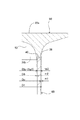
鋼管杭8は、例えば、図16に示すように、山の斜面S等の地中に鉛直方向に打ち込まれて設けられる。また、同図に示すように、鋼管杭用台座2の上面には、山の斜面Sに沿って伸びる道路等の構造物10の支柱12の下端が載置されて溶接により接合されている。鋼管杭用台座2は、その外径寸法が、継ぎ鋼管6及び支柱12のそれぞれの外径寸法よりも大きく設定されているので、鋼管杭8の打込み位置が支柱12に対して水平方向に多少ずれていても、鋼管杭用台座2上に構造物10の支柱12を確実に載置することができるようになっていた。
For example, as shown in FIG. 16, the
また、特許文献2のように、台座の形状を円筒状にする従来の構造もあった。すなわち、図19に示すように、鋼管杭用台座7は円筒状に形成され、この円筒状の台座7の上端面上には、上記道路等の構造物10の支柱12の下端が載置されて溶接により接合されている。そして台座7の外径寸法が、継ぎ鋼管6及び支柱12のそれぞれの外径寸法よりも大きく設定されているので、鋼管杭8の打込み位置が支柱12に対して水平方向に多少ずれていても、やはり、台座7上に構造物10の支柱12を確実に載置することができるようになっていた。
しかしながら、上記特許文献1に係る従来の鋼管杭用台座2においては、図17に示すように、その下端面2aが円形の単なる平面形状であって、この鋼管杭用台座2の下端面2aに接合される、継ぎ鋼管6上端の円環形状(図中、斜線で示す形状)とは異なっていると共に、鋼管杭用台座2の下端面2aの円形平面形状と継ぎ鋼管6の円環形状との間で、水平面上の断面積が急激に変化するため、この鋼管杭用台座2と継ぎ鋼管6との互いの接合部において応力集中が生じてしまうという問題があった。
However, in the conventional steel
また、上記従来の鋼管杭用台座2においては、鋼管杭8の上端の上に、継ぎ鋼管6の下端が溶接により突き合わせて連結された場合について説明したが、鋼管杭8の上端の上に直接鋼管杭用台座2を溶接により接合する場合も有り、この場合においても、鋼管杭用台座2と鋼管杭8との互いの接合部において応力集中が生じてしまうという問題があった。
Moreover, in the said conventional steel
また、上記特許文献2においても円筒状の鋼管杭用台座について同様の記載が含まれており、応力集中の問題は避けられないという問題があった。
Also, in
また、上記従来の鋼管杭用台座2においては、その形状の点から軽量化が十分に図られていないという問題があった。
Moreover, in the said conventional steel
そこで本発明は、上記問題点に鑑みて、鋼管杭または継ぎ鋼管との間の接合部で応力集中が発生するのを防止することができると共に、軽量化を図ることができる鋼管杭用台座を提供することを課題とするものである。 Therefore, in view of the above problems, the present invention provides a steel pipe pile pedestal capable of preventing stress concentration from occurring at a joint portion between a steel pipe pile or a joint steel pipe and reducing the weight. The issue is to provide.
上記課題を解決するために本発明は、
鋼管杭の上端の上に設けられる鋼管杭用台座であって、
鋼管杭用台座の下端面に開口する内部空間を有し、
鋼管杭用台座の下端面における前記開口の輪郭及び当該台座の外側の輪郭のそれぞれが、前記鋼管杭の上端水平面の内側及び外側それぞれの輪郭と略同一の大きさに形成され、
鋼管杭用台座の平板状の上段部と筒状の下段部との間の、前記内部空間を内側に有する中段部の水平面の外側の輪郭は、前記下段部から上段部に向かって徐々に拡大するように形成されると共に、当該輪郭上の任意の点における接線の水平方向に対する傾斜角が、当該台座の下段部側から上段部側に向かって徐々に縮小するように形成された曲線状部と、この曲線状部の当該台座の上段部側に連続する直線状部を有するように形成されていることを特徴とするものである。
In order to solve the above problems, the present invention
A steel pipe pile base provided on the upper end of the steel pipe pile,
It has an internal space that opens to the lower end surface of the steel pipe pile base,
Each of the outline of the opening on the lower end surface of the steel pipe pile pedestal and the outline of the outer side of the pedestal are formed in substantially the same size as the outline of the inner and outer sides of the upper horizontal surface of the steel pipe pile,
Between a flat upper portion and a tubular lower portion of the steel pipe pile pedestal, the outer contour of the horizontal plane of the middle part having the inner space inward gradually enlarged toward the upper portion from the lower portion It is formed so as to Rutotomoni inclination angle with respect to the horizontal direction of the tangent at any point on the contour, formed curved portion so as to reduce gradually toward the upper side from the lower side of the pedestal The curved portion is formed so as to have a continuous linear portion on the upper stage side of the pedestal .
また、本発明による鋼管杭用台座は、
鋼管杭用台座の中段部における内部空間の水平面の輪郭は、前記下段部側から上段部側に向かって徐々に縮小するように形成されると共に、当該輪郭上の任意の点における接線の水平方向に対する傾斜角が、当該台座の下段部側から上段部側に向かって徐々に縮小するように形成された曲線状部と、この曲線状部の当該台座の上段部側に連続する直線状部を有するように形成されていることを特徴とするものである。
The steel pipe pile base according to the present invention is
The contour of the horizontal plane of the internal space in the middle step of the steel pipe pile pedestal is formed so as to gradually decrease from the lower step side toward the upper step side, and the tangential horizontal direction at an arbitrary point on the contour A curved portion formed so that an inclination angle with respect to the pedestal gradually decreases from the lower step portion side toward the upper step portion side, and a linear portion continuous to the upper step portion side of the pedestal of the curved portion. It is formed so that it may have.
また、本発明による鋼管杭用台座は、
鋼管杭用台座の中段部と下段部における内部空間の水平面の輪郭が、鋼管杭用台座の下段部の下端から上段部側に向かって徐々に縮小するように形成されていることを特徴とするものである。
The steel pipe pile base according to the present invention is
The contour of the horizontal plane of the internal space in the middle part and the lower part of the steel pipe pile pedestal is formed so that it gradually decreases from the lower end of the lower part of the steel pipe pile pedestal toward the upper part side. Is.
また、本発明による鋼管杭用台座は、
鋼管杭用台座の中段部と下段部における内部空間の水平面の輪郭が、鋼管杭用台座の下端面から一定の高さ位置までの範囲にわたって一定の大きさに形成され、前記一定の高さ位置から鋼管杭用台座の上段部側に向かって徐々に縮小するように形成されていることを特徴とするものである。
The steel pipe pile base according to the present invention is
The contour of the horizontal plane of the inner space in the middle and lower stages of the steel pipe pile pedestal is formed with a constant size over a range from the lower end surface of the steel pipe pile pedestal to a certain height position, and the constant height position It is formed so that it may reduce gradually toward the upper-stage part side from the base for steel pipe piles .
このような本発明の鋼管杭用台座によれば、
鋼管杭の上端の上に設けられる鋼管杭用台座であって、
鋼管杭用台座の下端面に開口する内部空間を有し、
鋼管杭用台座の下端面における前記開口の輪郭及び当該台座の外側の輪郭のそれぞれが、前記鋼管杭の上端水平面の内側及び外側それぞれの輪郭と略同一の大きさに形成され、
鋼管杭用台座の上段部と下段部との間の、前記内部空間を内側に有する中段部の水平面の外側の輪郭が、前記下段部から上段部に向かって徐々に拡大するように形成されていることにより、
鋼管杭との接合部で応力集中が発生するのを防止することができると共に、当該鋼管杭用台座を軽量化することができる。
According to such a steel pipe pile pedestal of the present invention,
A steel pipe pile base provided on the upper end of the steel pipe pile,
It has an internal space that opens to the lower end surface of the steel pipe pile base,
Each of the outline of the opening on the lower end surface of the steel pipe pile pedestal and the outline of the outer side of the pedestal are formed in substantially the same size as the outline of the inner and outer sides of the upper horizontal surface of the steel pipe pile,
The outer contour of the horizontal surface of the middle step portion having the internal space between the upper step portion and the lower step portion of the steel pipe pile pedestal is formed so as to gradually expand from the lower step portion toward the upper step portion. By
While being able to prevent stress concentration from occurring at the joint with the steel pipe pile, the weight of the steel pipe pile base can be reduced.
また、本発明の鋼管杭用台座によれば、
鋼管杭用台座の中段部と下段部における内部空間の水平面の輪郭が、鋼管杭用台座の下端面から一定の高さ位置までの範囲にわたって一定の大きさに形成され、前記一定の高さ位置から鋼管杭用台座の上段部側に向かって徐々に縮小するように形成されていることにより、
鋼管杭との接合部で応力集中が発生するのを防止できる確実性を向上することができると共に、この接合部を接合し易くすることができる。
Moreover, according to the steel pipe pile pedestal of the present invention,
The contour of the horizontal plane of the inner space in the middle and lower stages of the steel pipe pile pedestal is formed with a constant size over a range from the lower end surface of the steel pipe pile pedestal to a certain height position, and the constant height position From being formed to gradually shrink toward the upper stage side of the steel pipe pile pedestal,
It is possible to improve the reliability with which stress concentration can be prevented from occurring at the joint portion with the steel pipe pile, and to make it easy to join the joint portion.
また、本発明の鋼管杭用台座によれば、
鋼管杭用台座の中段部と下段部における内部空間の水平面の輪郭が、鋼管杭用台座の下段部の下端から上段部側に向かって徐々に縮小するように形成されていることにより、
鋼管杭との接合部で応力集中が発生するのを防止することができると共に、当該鋼管杭用台座を軽量化することができる。
Moreover, according to the steel pipe pile pedestal of the present invention,
By forming the contour of the horizontal plane of the internal space in the middle and lower stages of the steel pipe pile pedestal so that it gradually decreases from the lower end of the lower part of the steel pipe pile pedestal toward the upper stage side,
While being able to prevent stress concentration from occurring at the joint with the steel pipe pile, the weight of the steel pipe pile base can be reduced.
また、本発明の鋼管杭用台座によれば、
鋼管杭用台座の中段部の、高さ方向に伸びる軸線に沿って切断した断面の外側の輪郭上の任意の点における接線の水平方向に対する傾斜角が、当該台座の下段部側から上段部側に向かって徐々に縮小するように形成されていることにより、
鋼管杭と鋼管杭用台座との接合部で応力集中が発生するのを防止できる確実性を向上することができると共に、鋼管杭用台座を更に軽量化することができる。
Moreover, according to the steel pipe pile pedestal of the present invention,
The inclination angle of the tangent to the horizontal direction at an arbitrary point on the outer contour of the cross section cut along the axis extending in the height direction of the middle step of the steel pipe pile base is from the lower step side to the upper step side of the base. By being formed to gradually shrink toward
The reliability that can prevent stress concentration from occurring at the joint between the steel pipe pile and the steel pipe pile base can be improved, and the steel pipe pile base can be further reduced in weight.
また、本発明の鋼管杭用台座によれば、
前記内部空間の高さ方向に伸びる軸線に沿って切断した断面の輪郭上の任意の点における接線の水平方向に対する傾斜角が、鋼管杭用台座の下段部側から上段部側に向かって徐々に縮小するように形成されていることにより、
鋼管杭と鋼管杭用台座との接合部で応力集中が発生するのを防止できる確実性を向上することができると共に、鋼管杭用台座を更に軽量化することができる。
Moreover, according to the steel pipe pile pedestal of the present invention,
The inclination angle with respect to the horizontal direction of the tangent at an arbitrary point on the profile of the cross section cut along the axis extending in the height direction of the internal space is gradually increased from the lower step side to the upper step side of the steel pipe pile base. By being formed to shrink,
The reliability that can prevent stress concentration from occurring at the joint between the steel pipe pile and the steel pipe pile base can be improved, and the steel pipe pile base can be further reduced in weight.
また、本発明の鋼管杭用台座によれば、
鋼管杭用台座の上段部の高さが、当該台座の高さ全体の略5分の1であるように形成されていることにより、
鋼管杭用台座を更に軽量化することができる。
Moreover, according to the steel pipe pile pedestal of the present invention,
By being formed so that the height of the upper part of the steel pipe pile pedestal is approximately one fifth of the entire height of the pedestal,
The steel pipe pile base can be further reduced in weight.
以下、本発明に係る鋼管杭用台座を実施するための最良の形態について、図面に基づいて具体的に説明する。
図1から図5は、本発明の第1の実施の形態に係る鋼管杭用台座20について説明するために参照する図である。従来と同様の部分には同じ符号を用いて説明し、従来と同様の構成についての重複する説明はできるだけ省略するものとする。
Hereinafter, the best mode for carrying out the steel pipe pile base according to the present invention will be specifically described with reference to the drawings.
FIGS. 1 to 5 are views referred to for explaining a steel
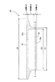
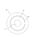
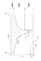
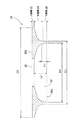
図1及び図2は、本実施の形態に係る鋼管杭用台座20を示す側面断面図及び下面図である。この鋼管杭用台座20は、図4,5に示す丸形鋼管である鋼管杭8の上端の上に溶接で接合されるものである。また、鋼管杭用台座20は、鋳造や鍛造により製造することができるものである。
FIG.1 and FIG.2 is side sectional drawing and the bottom view which show the
鋼管杭用台座20は、図1に示すように、その外周形状に対応して、高さ方向に上段部22、中段部24、及び下段部26に区分けすることができる。これら上段部22、中段部24、及び下段部26のそれぞれは、以下のような形状に形成されている。
As shown in FIG. 1, the steel
ここで、以下の説明において、鋼管杭用台座20の高さ方向(図1中、上下方向)に伸びる軸線に直角の水平面の概念の中には、上段部22から下段部26迄の高さ範囲内における任意の高さの水平断面と、鋼管杭用台座20の上端面22a及び下端面26aが含まれるものとする。
Here, in the following description, the height from the upper step portion 22 to the
鋼管杭用台座20の下段部26は、その水平面(図1中の仮想線X−Xで切断したときの不図示の水平断面)の外側の輪郭が、図4,5に示すように、その下端面26aに溶接される鋼管杭8の上端の外側の輪郭と同一の大きさの直径(外径)の円形状に形成されている。
As shown in FIGS. 4 and 5, the
また、鋼管杭用台座20の上段部22は、その水平面の外側の輪郭が、前記下段部26の水平面の外側の輪郭と大きさが異なる円形状に形成されている。すなわち、この上段部22の水平面の円形状外側の直径(図1中、寸法D2)は、下段部26の円形状外側の直径(図1中、寸法D1)よりも大きくなるように形成されている。
Further, the upper step portion 22 of the steel
また、鋼管杭用台座20における上段部22と下段部26との間の中段部24は、その水平面の外側の輪郭が円形状に形成されていると共に、その円形状の直径は、下段部26から上段部22に向かって徐々に大きくなっていくように形成されている。
Further, the middle step portion 24 between the upper step portion 22 and the
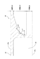
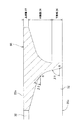
そして、鋼管杭用台座20の中段部24は、図3に示すように、その高さ方向(図3中、上下方向)に伸びる軸線に沿って切断した断面の外側の輪郭上に配置される、異なる高さの任意の2点P,Qにおけるそれぞれの接線の、水平方向に対する傾斜角α1,α2を比較すると、常に、上側の点Qにおける傾斜角α2の方が、下側の点Pにおける傾斜角α1の大きさより小さくなっており、上記傾斜角は下段部26側から上段部22側に向かって徐々に縮小するように形成されている。
And the middle step part 24 of the steel
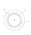
また、鋼管杭用台座20には、図1に示すように、その下端面26aに開口する内部空間30が形成されている。この内部空間30の開口は、鋼管杭用台座20の下端面26aに溶接される、図4,5に示す鋼管杭8の水平面の内側の円形状の直径(内径)と同じ大きさの直径の円形状に形成されている。また、鋼管杭用台座20の上段部22の水平面中央部には、その上端面22aに開口し、内部空間30に連通する孔32が形成されている。
Moreover, as shown in FIG. 1, the steel
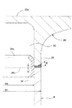
次に、図4及び図5に基づいて、本実施の形態に係る鋼管杭用台座20が、溶接により鋼管杭8に接合されたときの状態について説明する。図4は、鋼管杭用台座20が、溶接により鋼管杭8の上に接合した状態を示す断面図である。また、図5は、このような鋼管杭用台座20と鋼管杭8の接合部分を拡大して示す、拡大断面図である。
Next, based on FIG.4 and FIG.5, the state when the
前述のように、鋼管杭用台座20の下端面26aの外径と鋼管杭8の外径は同じ大きさで、鋼管杭用台座20の内部空間30の下端面26aの開口の直径と鋼管杭8の内径も同じ大きさなので、鋼管杭用台座20の下段部26の外周面と鋼管杭8の外周面は同一面状に配置され、鋼管杭用台座20の内部空間30の内周面と鋼管杭8の内周面も同一面状に配置することが可能となっている。
As described above, the outer diameter of the
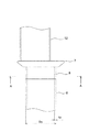
鋼管杭8の上端部の内周面には、高さが低い筒状の裏当金34の略下半分が固定されており、裏当金34の略上半分は鋼管杭8の上端面から上方に突出している。そして、裏当金34の高さ上端部には、鋼管杭用台座20の内部空間30の内周面から離れるような傾斜部34aが形成されている。
On the inner peripheral surface of the upper end portion of the
このため、鋼管杭用台座20を鋼管杭8の上方から降ろしてその内部空間30の内周面を裏当金34の上半分の外周面に嵌合させることにより、鋼管杭8の上に鋼管杭用台座20の下端面26aを水平方向にずれることなく載置させることができる。この後で鋼管杭用台座20の下端面26aと鋼管杭8の上端面との間を溶接するが、図5に示すように、この両者間には隙間Hが形成されると共に、鋼管杭用台座20の下段部26の下端部には開先Kが形成された状態で溶接されている。
For this reason, the steel
上記溶接は、上記隙間Hと開先Kの内部に溶材を溶かし込むことにより行われる。上述のように、鋼管杭用台座20の下段部26の内周面と、鋼管杭8上端の内周面には、それぞれにわたって裏当金34が設けられているので、上記隙間Hから内部に向かって溶かし込まれた溶材は裏当金34に遮られて、鋼管杭8の肉厚の内側にこぼれ落ちることはないようになっている。
The welding is performed by melting a molten material into the gap H and the groove K. As described above, the backing
このような本実施の形態に係る鋼管杭用台座20によれば、その下端面26aの形状が円環形状となるように形成されていると共に、この鋼管杭用台座20に接合される鋼管杭8の水平断面の形状も同じ大きさの円環形状に形成されていて、鋼管杭用台座20の内部空間30の内周面と鋼管杭8の内周面のそれぞれにわたって裏当金34が設けられているため、鋼管杭用台座20の内部空間30の内周面と鋼管杭8の内周面との間、及び、鋼管杭用台座20の下端部26の外周面と鋼管杭8の外周面との間に、水平方向にずれる大きな段差ができるのを防止して、その接合部に応力集中が発生するのを防止することができる。
According to the steel
また、本実施の形態に係る鋼管杭用台座20によれば、図3に示すように、その中段部24の水平面の外側の円形状の直径が、鋼管杭用台座20の下段部26側から上段部22側に向かって徐々に大きくなっていくように形成され、このときの鋼管杭用台座20の高さ方向に伸びる軸線に沿って切断した断面の外側の輪郭上の任意の点における接線の、水平方向に対する傾斜角が徐々に小さくなっていくように形成されていると共に、鋼管杭用台座20の内部に内部空間30が形成されているので、鋼管杭用台座20を従来よりも軽量化することができる。
Moreover, according to the steel
また、本実施の形態に係る鋼管杭用台座20によれば、鋼管杭用台座20の水平面中央部には、その上端面22aに開口し、内部空間30に連通する孔32が形成されているので、鋼管杭用台座20全体を軽量化することができると共に、鋼管杭用台座20を製造する際に用いられるその原材料の量を低減させてコストダウンを図ることができる。
Further, according to the steel
なお、この第1の実施の形態においては、溶接用の開先Kが鋼管杭用台座20の下端面26aの外周部に形成されているが、溶接用の開先Kは鋼管杭8の上端面の外周部に形成してもよく、或はこれらの両者に開先Kを形成してもよい。
In this first embodiment, the welding groove K is formed on the outer peripheral portion of the
次に、図6から図8は、本発明の第2の実施の形態に係る鋼管杭用台座45について説明するために参照する図である。
前記第1の実施の形態に係る鋼管杭用台座20と同様の部分には同じ符号を用いて説明し、同様の構成についての重複する説明はできるだけ省略するものとする。
Next, FIGS. 6-8 is a figure referred in order to demonstrate the steel
Parts similar to those of the steel
図6は、本実施の形態に係る鋼管杭用台座45の一部を示す拡大断面図であって、前記第1の実施の形態を説明する際に参照した図3に相当する図である。同図に示すように、鋼管杭用台座45は、前記第1の実施の形態に係る鋼管杭用台座20の内部空間30の代わりに、内部空間46を有している。
FIG. 6 is an enlarged cross-sectional view showing a part of the steel
この内部空間46は、前記第1の実施の形態に係る鋼管杭用台座20の内部空間30と同様に、下端面26aに開口するように形成されている。また、この内部空間46の下端面26aにおける開口は、やはり前記実施の形態に係る鋼管杭用台座20の内部空間30と同様に、下端面26aに溶接される、図7,8に示す鋼管杭8の水平断面の内側の円形状の直径と略同じ直径の円形状に形成されている。
This
また、内部空間46は、図6に示すように、同図中の寸法L0で示される、下端面26aからその上方の一定の高さ位置までの範囲にわたって、この内部空間46の水平断面の円形状(輪郭)の直径の大きさが、鋼管杭8の水平面の内側の円形状の直径(内径)と同じ大きさの直径の円形状に形成されている。
Further, as shown in FIG. 6, the
また、この内部空間46は、その高さ方向の全体の範囲のうちの、寸法L0で示される範囲より上方の寸法L2で示される範囲内においては、この内部空間46の水平断面の円形状(輪郭)の直径の大きさが、高さ寸法L0の範囲との間の境界から上方に向かって徐々に小さくなるように形成されている。
Further, the
このように、本発明の第2の実施の形態に係る鋼管杭用台座45は、寸法L2で示される高さ範囲内において、その下側の寸法L0で示される高さ範囲との間の境界から上方に向かって内部空間46の水平面の直径が徐々に小さくなるように形成されている点が、前記第1の実施の形態に係る鋼管杭用台座20ののように、鋼管杭用台座20の中段部24と下段部26の高さ範囲にわたって、内部空間30の水平面の直径が、中段部24の最上部のR曲面部を除き、一定の大きさに形成されるようになっていた点と異なっている。
Thus, the steel
また、鋼管杭用台座45の内部空間46は、図6に示す断面、すなわち、その高さ方向に伸びる軸線に沿って切断した断面の内側輪郭上に配置される、異なる高さの任意の2点R,Sにおける、水平方向に対する傾斜角β1,β2を比較すると、点Rより上側の点Sにおける傾斜角β2の方が、点Sより下側の点Rにおける傾斜角β1より小さくなるように形成されている。
Further, the
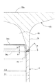
次に、図7及び図8に基づいて、本実施の形態に係る鋼管杭用台座45が、溶接により鋼管杭8に接合されたときの状態について説明する。図7は、鋼管杭用台座45が、溶接により鋼管杭8の上に接合した状態を示す断面図である。また、図8は、このような鋼管杭用台座45と鋼管杭8の接合部分を示す拡大断面図である。
Next, based on FIG.7 and FIG.8, the state when the
鋼管杭用台座45の下端面26aの外径と鋼管杭8の外径は同じ大きさであって、前記第1の実施の形態と同様であるので、鋼管杭用台座20の下段部26の外周面と鋼管杭8の外周面は同一面状に配置される。また、鋼管杭用台座45における寸法L0で示される高さ範囲内の内部空間46の水平面の円形状の直径と鋼管杭8の内径も同じ大きさなので、鋼管杭用台座45における寸法L0で示される高さ範囲内の内部空間46の内周面と鋼管杭8の内周面も同一面状に配置することが可能となっている。
Since the outer diameter of the
これにより、この鋼管杭用台座45と鋼管杭8は、前記第1の実施の形態に係る鋼管杭用台座20と鋼管杭8との間の接合構造と同様に、裏当金34を用いて互いの位置合せを容易に行なって互いに接合されるようになっている。
Thereby, this steel
このような本発明の第2の実施の形態に係る鋼管杭用台座45によれば、その下端面26aの形状が円環形状となるように形成されていると共に、この鋼管杭用台座45に接合される鋼管杭8の水平断面の形状も同じ大きさの円環形状に形成されていて、鋼管杭用台座45における寸法L0の高さ範囲内の内部空間46の内周面と鋼管杭8の内周面のそれぞれにわたって裏当金34が設けられているため、鋼管杭用台座45の内部空間46の内周面と鋼管杭8の内周面との間、及び、鋼管杭用台座45の下端部26の外周面と鋼管杭8の外周面との間に、水平方向にずれる大きな段差ができるのを防止して、その接合部に応力集中が発生するのを防止することができる。
According to the steel
また、本実施の形態に係る鋼管杭用台座45によれば、前記第1の実施の形態と同様に、その中段部24の水平面の外側の円形状が、その下段部26から上段部22に向かって徐々に大きくなっていくように形成され、このときの鋼管杭用台座45の高さ方向に伸びる軸線に沿って切断した断面の外側の輪郭上の任意の点における接線の水平方向に対する傾斜角が徐々に小さくなっていくように形成されていると共に、鋼管杭用台座45の内部に内部空間46が形成されているので、鋼管杭用台座45を従来よりも軽量化することができる。
Further, according to the steel
また、本実施の形態に係る鋼管杭用台座45によれば、図7に示すように、前記第1の実施の形態と同様に、鋼管杭用台座45の水平面中央部には、その上端面22aに開口し、内部空間46に連通する孔32が形成されているので、鋼管杭用台座45全体を軽量化することができると共に、鋼管杭用台座45を製造する際に用いられるその原材料の量を低減させてコストダウンを図ることができる。
In addition, according to the steel
また、本実施の形態に係る鋼管杭用台座45によれば、図6に示すように、同図中の寸法L2で示される範囲内において、その内部空間46の水平面の円形状(輪郭)の大きさが、上方に向かって徐々に小さくなっていくように形成され、このときの前記傾斜角β2がβ1より徐々に小さくなっていくように形成されていることにより、鋼管杭用台座45内に応力集中が発生するのを防止することができる。
Further, according to the steel
次に、図9から図14は、本発明の第3の実施の形態に係る鋼管杭用台座50について説明するために参照する図である。
前記第1の実施の形態に係る鋼管杭用台座20と同様の部分には同じ符号を用いて説明し、同様の構成についての重複する説明はできるだけ省略するものとする。
Next, FIGS. 9 to 14 are views referred to for explaining a steel
Parts similar to those of the steel
この第3の実施の形態は、図15に示す従来の鋼管杭用台座2と同様に、鋼管杭用台座50と鋼管杭8との間に継ぎ鋼管6を挟んで構成するようにしたものである。
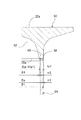
図9は、本実施の形態に係る鋼管杭用台座50を示す側面断面図である。同図に示すように、鋼管杭用台座50は、前記第1の実施の形態に係る鋼管杭用台座20の内部空間30の代わりに、内部空間52を有している。
In the third embodiment, similarly to the conventional steel
FIG. 9 is a side sectional view showing a steel
この内部空間52は、前記第1の実施の形態に係る鋼管杭用台座20の内部空間30と同様に、下端面26aに開口するように形成されている。また、この内部空間52の下端面26aにおける開口は、やはり前記第1の実施の形態に係る鋼管杭用台座20の内部空間30と同様に、下端面26aに溶接される、図11,12に示す継ぎ鋼管6Aの水平断面の内側の円形状の直径と略同じ直径の円形状に形成されている。
This
また、内部空間52は、図9中の寸法L1で示される、下端面26aからその上方の一定高さまでの範囲内において、この内部空間52の水平断面の円形状の直径の大きさが、後述するような継ぎ鋼管6A,6B等の、肉厚が異なる各種の継ぎ鋼管6の水平断面の内側の円形状の直径から溶着金属40(図12及び図14参照)の肉盛り部の水平寸法分(2×m2)を差し引いた直径が、高さ方向のいずれかの高さにおける水平面の内側の円形状の直径となるように、下端面26aから上方に向かって徐々に小さくなるように形成されている。
Further, the
このように、本発明の第3の実施の形態に係る鋼管杭用台座50は、下端面26aから上方に向かって内部空間52の水平断面の円形状の直径が徐々に小さくなるように形成されている点が、前記第1の実施の形態に係る鋼管杭用台座20の内部空間30のように、鋼管杭用台座20の中段部24と下段部26の高さ範囲にわたって、内部空間30の水平断面の円形状の直径が略一定の大きさに形成されるようになっていた点と異なっている。
Thus, the steel
すなわち、鋼管杭用台座50の内部空間52は、図9中の寸法L1で示される高さ範囲を含む、その高さ方向全体の範囲(図9中、寸法L2)にわたって、水平断面の円形状の直径が、下端面26aから上方に向かって徐々に小さくなるように形成されている。
That is, the
そして、鋼管杭用台座50の内部空間52は、図10に示すように、その高さ方向に伸びる軸線に沿って切断した断面の内側輪郭上に配置される、異なる高さの任意の2点R,Sにおける、水平方向に対する傾斜角β1,β2を比較すると、所定の高さより上側の点Sにおける傾斜角β2の方が、所定の高さより下側の点Rにおける傾斜角β1より小さくなるように形成されている。
And the
次に、図11,12、及び図13,14に基づいて、本実施の形態に係る鋼管杭用台座50と、この鋼管杭用台座50に接合される、後述するような継ぎ鋼管6A及び6Bのそれぞれについて、これらが互いに接合される前後それぞれの状態を説明する。
Next, based on FIGS. 11, 12, and 13, 14, a steel
ここで、鋼管杭用台座50は、以下に説明するように、同一の外径寸法Dpであって、各肉厚tpが異なる各種の継ぎ鋼管6のいずれに対しても、溶接により接合されることができるようになっている。
Here, as will be described below, the steel
図11及び図12は、このような各種肉厚の継ぎ鋼管6のうち、使用限度内で最も薄い肉厚tp1の継ぎ鋼管6Aに対して鋼管杭用台座50が接合される場合の前後それぞれの状態を説明する図である。
FIG. 11 and FIG. 12 show the respective cases before and after the steel
また、図13及び図14は、各種肉厚の継ぎ鋼管6のうち、使用限度内で最も厚い肉厚tp2の継ぎ鋼管6Bに対して鋼管杭用台座50が接合される場合の前後それぞれの状態を説明する図である。
Moreover, FIG.13 and FIG.14 is the state of each before and after when the
まず、継ぎ鋼管6Aには、図11に示すように、その外周と内周のそれぞれの、鋼管杭用台座50側の上端部に開先加工が施されていることにより、その円周方向の長さ全体にわたって、断面形状が山形状に形成されるような、2つの斜面が形成されている(図12参照)。
First, as shown in FIG. 11, the
このような継ぎ鋼管6Aの上記断面形状における2つの斜面のそれぞれと、鋼管杭用台座50の下端面26aとの間には、図12に示すように、鋼管杭用台座50の下端面26aと継ぎ鋼管6Aの2つの斜面とを溶接する溶着金属38,40が盛られて、両者間を溶着する。
Between each of the two slopes in the above cross-sectional shape of the
このような溶着金属38,40のうち、継ぎ鋼管6Aの肉厚(図12中、寸法tp1)から外側及び内側にはみ出して盛られる部分(図12中、寸法m1,m2の部分)は、肉盛り部と呼ばれ、このような肉盛り部の水平方向の寸法はおよそ3mm程度に設定されるが、この値に限定されないことはいうまでもない。
Of such welded
図12に示す鋼管杭用台座50の下端面26aは、その水平面外側の円形状の直径(図12及び図9中、寸法D1)が、継ぎ鋼管6Aの水平面外側の円形状の直径(図12中、寸法Dp)よりも、半径長さ当たり、溶着金属38の肉盛り部の水平方向の寸法m1だけ大きく形成されている。つまり、鋼管杭用台座50の下端面26aの水平面外側の円形状の直径D1は、(D1=Dp+2m1)の関係が成立するように設定されて形成されている。
The
鋼管杭用台座50は、予め、施工現場に搬入される前の段階において、図12に示すように、その内部空間52の下端面26aにおける開口の円形状の直径が、継ぎ鋼管6Aの水平断面の内側の円形状の直径(図12中、寸法(Dp−2tp1))から、半径長さ当たり、溶着金属40の肉盛り部の長さ分(図12中、寸法m2)を差し引いた直径D4となるように形成されている。つまり、鋼管杭用台座50の内部空間52は、その開口の円形状の直径D4が、(D4=(Dp−2tp1)−2m2)の関係が成立するように設定されて形成されている。
As shown in FIG. 12, the steel
これにより、鋼管杭用台座50の下端面26aは、継ぎ鋼管6Aに接合される場合には、図12に示すように、上記のような寸法関係の状態で、溶接により継ぎ鋼管6Aの上端部に接合されることができるようになっている。
Thereby, when the
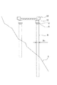
また、鋼管杭用台座50は、図13に示すように下端面26aから寸法zで示す、高さ部分を切除するよう加工して、新たな下端面26bを形成することにより、図14に示すように、この新たな下端面26bに使用限度内で最も厚い肉厚tp2の継ぎ鋼管6Bを接合することができるようになる。
Moreover, the steel
つまり、鋼管杭用台座50は、図9に示すように、その内部空間52の水平断面の円形状の直径が、図9中の寸法L1の高さ範囲内で、上方に向かって徐々に小さくなるように形成されているので、図14に示す継ぎ鋼管6Bの水平面内側の円形状の直径(Dp−2tp2)に対応する鋼管杭用台座50の前記寸法zを設定することができる。
That is, as shown in FIG. 9, the steel
鋼管杭用台座50は、このような寸法zの高さ部分を切除することにより、図14に示すように、この鋼管杭用台座50の新たな下端面26bにおいて、継ぎ鋼管6Bの水平面の内側の輪郭の直径(Dp−2tp2)から、半径長さ当たり、溶着金属40の肉盛りの長さ分(図14中、寸法m2)を差し引いた直径D5で、内部空間52が新たな下端面26bに開口するようにできる。
As shown in FIG. 14, the steel
また、継ぎ鋼管6Bは、図13に示すように、鋼管杭用台座50の切除した高さ分の寸法zと同じ寸法分だけ長く形成することができる(図13中、継ぎ鋼管6Bの長さ寸法H+z)。これにより、鋼管杭用台座50の下端面26bは、使用限度内で最も厚い肉厚tp2の継ぎ鋼管6Bに接合し、このような継ぎ鋼管6Bの上端部の上に接合したときに、鋼管杭用台座50の上端面22aの高さが、他の台座50の上端面22aの高さとの関係で、適切な高さに設定されるようにすることができる。
Further, as shown in FIG. 13, the
このような第3の実施の形態においては、継ぎ鋼管6A,6Bやその他の中間の肉厚の継ぎ鋼管6の下端部は、前記第1の実施の形態に係る図4,5に示すように、内側に裏当金34を設けると共に、鋼管杭用台座50の下端部等の外側に開先を形成して溶接することにより、その下に配置される鋼管杭8に連結することができる。
In the third embodiment, the lower end portions of the
このような本発明の第3の実施の形態に係る鋼管杭用台座50によれば、前記第1の実施の形態と同様に、その下端面26a又は下端面26bの水平面の形状が円環形状となるように形成されていると共に、この鋼管杭用台座50に接合される継ぎ鋼管6A又は6Bの水平面も同様に円環形状に形成されているため、鋼管杭用台座50の内部空間52の内周面と継ぎ鋼管6A又は6Bの内周面、及び、鋼管杭用台座50の下端部26の外周面と継ぎ鋼管6A又は6Bの外周面との接合部に大きな段差ができるのを防止して、その接合部に応力集中が発生するのを防止することができる。
According to the steel
また、本実施の形態に係る鋼管杭用台座50によれば、この鋼管杭用台座50と接合し得る様々な肉厚の継ぎ鋼管6との相互間において大きな段差ができないように、その下端面26aと26bの間の、内側の円形状の直径を変化させることができるので、鋼管杭用台座50と継ぎ鋼管6との接合部に大きな段差ができるのを防止して、その接合部に応力集中が発生するのを防止することができる。
In addition, according to the steel
また、本実施の形態に係る鋼管杭用台座50によれば、前記第1の実施の形態と同様に、その中段部24の水平面の外側の円形状が、その下段部26から上段部22に向かって徐々に大きくなっていくように形成され、このときの鋼管杭用台座50の高さ方向に伸びる軸線に沿って切断した断面の外側の輪郭上の任意の点における接線の水平方向に対する傾斜角が徐々に小さくなっていくように形成されていると共に、鋼管杭用台座50の内部に内部空間52が形成されているので、鋼管杭用台座50を従来よりも軽量化することができる。
Further, according to the steel
また、本実施の形態に係る鋼管杭用台座50によれば、図10に示すように、その内部空間52の水平面の円形状の大きさが、上方に向かって徐々に小さくなっていくように形成され、このときの前記傾斜角β2がβ1より徐々に小さくなっていくように形成されているので、継ぎ鋼管6の内部と鋼管杭用台座50の内部との接合部に大きな段差ができないように、その下端面26aと26bの間で変化させることができるので、その接合部における応力集中の発生を防止できる確実性を更に向上することができる。
Further, according to the steel
また、本実施の形態に係る鋼管杭用台座50によれば、前記第1の実施の形態と同様に、鋼管杭用台座50の水平面中央部には、その上端面22aに開口し、内部空間52に連通する孔32が形成されているので、鋼管杭用台座50全体を軽量化することができると共に、鋼管杭用台座50を製造する際に用いられるその原材料の量を低減させてコストダウンを図ることができる。
In addition, according to the steel
なお、前記第1、第2及び第3の実施の形態に係る鋼管杭用台座20,45,50の水平中央部には、孔32が形成されることにより軽量化が図られていたが、場合によっては、例えば強度の向上の方を重視する場合等においては、この孔32は形成されていなくてもよい。
In addition, in the horizontal center part of the steel
また、前記第3の実施の形態に係る鋼管杭用台座50においては、その内部空間52(図9参照)の水平面の円形状の大きさが、図9中の寸法L2の範囲内で、下端面26aから上方に向かって徐々に小さくなるように形成されていたが、他の実施形態として、内部空間52は、図9中の寸法L2の高さ範囲内における、寸法L1で示す高さ範囲以外の他の高さ範囲内において、その水平面の円形状の大きさが一定となるように形成されていてもよい。
Further, in the steel
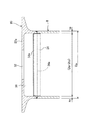
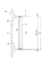
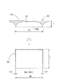
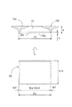
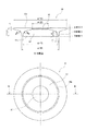
例えば、図15における鋼管杭8及び継ぎ鋼管6の径Dpを500mm、板厚tpを9mmとし、図15の支柱12と鋼管杭用台座2との心ずれ量の最大許容値±100mmを考慮した場合の鋼管杭用台座50の寸法を図18に示す。このとき、鋼管杭用台座50の自重は130kg程度である。また、FEM解析結果によると、支柱12と鋼管杭用台座2との心ずれ量が最大100mm発生した状態を考慮して鉛直荷重1000kNを作用させた場合、最大応力は160N/mm2であり、局部的な応力集中も発生しない。
For example, the diameter Dp of the
また、前記第3の実施の形態に係る鋼管杭用台座50においては、使用限度内における肉厚が最小と最大の継ぎ鋼管6Aと6Bを用いた場合について説明したが、肉厚がそれら最小と最大の肉厚の中間の継ぎ鋼管を用いてもよいことはいうまでもない。
Moreover, in the steel
また、前記第1、第2及び第3の実施の形態においては、鋼管杭用台座20,45,50の下端面26aの形状が円環形状に形成され、鋼管杭8、継ぎ鋼管6の水平面の形状も円環形状に形成されている場合について説明したが、鋼管杭用台座の下端面の形状は円環形状に限定する必要は無く、また、鋼管杭の水平断面の形状も円環形状に限定する必要は無い。すなわち、鋼管杭用台座の下端面の形状は四角環形状等の多角環形状であってもよく、また、鋼管杭、継ぎ鋼管の水平断面の形状も四角環形状等の多角環形状であってもよい。
Moreover, in the said 1st, 2nd and 3rd embodiment, the shape of the
また、前記第3の実施の形態においては、継ぎ鋼管を用いた場合について説明したが、前記第1、第2の実施の形態においても鋼管杭と台座の間に継ぎ鋼管を設けることは可能である。 Moreover, in the said 3rd Embodiment, although the case where a joint steel pipe was used was demonstrated, it is possible to provide a joint steel pipe between a steel pipe pile and a base also in the said 1st, 2nd embodiment. is there.
2 鋼管杭用台座
6,6A,6B 継ぎ鋼管
7 鋼管杭用台座
8 鋼管杭
10 構造物
12 支柱
20 鋼管杭用台座
22 上段部
22a 上端面
24 中段部
26 下段部
26a,26b 下端面
30 内部空間
32 孔
34 裏当金
38,40 溶着金属
45 鋼管杭用台座
46 内部空間
50 鋼管杭用台座
52 内部空間
2 Steel
Claims (4)
鋼管杭用台座の下端面に開口する内部空間を有し、
鋼管杭用台座の下端面における前記開口の輪郭及び当該台座の外側の輪郭のそれぞれが、前記鋼管杭の上端水平面の内側及び外側それぞれの輪郭と略同一の大きさに形成され、
鋼管杭用台座の平板状の上段部と筒状の下段部との間の、前記内部空間を内側に有する中段部の水平面の外側の輪郭は、前記下段部から上段部に向かって徐々に拡大するように形成されると共に、当該輪郭上の任意の点における接線の水平方向に対する傾斜角が、当該台座の下段部側から上段部側に向かって徐々に縮小するように形成された曲線状部と、この曲線状部の当該台座の上段部側に連続する直線状部を有するように形成されている
ことを特徴とする鋼管杭用台座。 A steel pipe pile base provided on the upper end of the steel pipe pile,
It has an internal space that opens to the lower end surface of the steel pipe pile base,
Each of the outline of the opening on the lower end surface of the steel pipe pile pedestal and the outline of the outer side of the pedestal are formed in substantially the same size as the outline of the inner and outer sides of the upper horizontal surface of the steel pipe pile,
Between a flat upper portion and a tubular lower portion of the steel pipe pile pedestal, the outer contour of the horizontal plane of the middle part having the inner space inward gradually enlarged toward the upper portion from the lower portion It is formed so as to Rutotomoni inclination angle with respect to the horizontal direction of the tangent at any point on the contour, formed curved portion so as to reduce gradually toward the upper side from the lower side of the pedestal And a steel pipe pile pedestal, characterized in that it is formed so as to have a linear part continuous to the upper stage part side of the pedestal of the curved part .
ことを特徴とする請求項1に記載の鋼管杭用台座。 The contour of the horizontal plane of the internal space in the middle step of the steel pipe pile pedestal is formed so as to gradually decrease from the lower step side toward the upper step side, and the tangential horizontal direction at an arbitrary point on the contour A curved portion formed so that an inclination angle with respect to the pedestal gradually decreases from the lower step portion side toward the upper step portion side, and a linear portion continuous to the upper step portion side of the pedestal of the curved portion. steel pipe pile pedestal according to claim 1, characterized in that it is formed to have.
ことを特徴とする請求項1又は2に記載の鋼管杭用台座。 It is characterized in that the contour of the horizontal space of the inner space in the middle and lower stages of the steel pipe pile pedestal is formed so as to gradually decrease from the lower end of the lower part of the steel pipe pile pedestal toward the upper stage side. The steel pipe pile base according to claim 1 or 2 .
ことを特徴とする請求項1に記載の鋼管杭用台座。 The contour of the horizontal plane of the inner space in the middle and lower stages of the steel pipe pile pedestal is formed with a constant size over a range from the lower end surface of the steel pipe pile pedestal to a certain height position, and the constant height position The steel pipe pile pedestal according to claim 1, wherein the steel pipe pile pedestal is formed such that the steel pipe pile pedestal gradually shrinks toward the upper stage side of the steel pipe pile pedestal.
Priority Applications (1)
| Application Number | Priority Date | Filing Date | Title |
|---|---|---|---|
| JP2008322972A JP5259372B2 (en) | 2008-12-18 | 2008-12-18 | Steel pipe pile base |
Applications Claiming Priority (1)
| Application Number | Priority Date | Filing Date | Title |
|---|---|---|---|
| JP2008322972A JP5259372B2 (en) | 2008-12-18 | 2008-12-18 | Steel pipe pile base |
Publications (2)
| Publication Number | Publication Date |
|---|---|
| JP2010144431A JP2010144431A (en) | 2010-07-01 |
| JP5259372B2 true JP5259372B2 (en) | 2013-08-07 |
Family
ID=42565135
Family Applications (1)
| Application Number | Title | Priority Date | Filing Date |
|---|---|---|---|
| JP2008322972A Active JP5259372B2 (en) | 2008-12-18 | 2008-12-18 | Steel pipe pile base |
Country Status (1)
| Country | Link |
|---|---|
| JP (1) | JP5259372B2 (en) |
Family Cites Families (1)
| Publication number | Priority date | Publication date | Assignee | Title |
|---|---|---|---|---|
| JP2004239016A (en) * | 2003-02-10 | 2004-08-26 | Nippon Steel Corp | Connection structure of steel pipe column and steel pipe pile |
-
2008
- 2008-12-18 JP JP2008322972A patent/JP5259372B2/en active Active
Also Published As
| Publication number | Publication date |
|---|---|
| JP2010144431A (en) | 2010-07-01 |
Similar Documents
| Publication | Publication Date | Title |
|---|---|---|
| US7490631B2 (en) | Integrally formed flanged metal pipe and method of manufacturing thereof | |
| WO2016132650A1 (en) | Joint mechanism and connection method for steel pipe | |
| JP2011089302A (en) | Weldless joint for pile | |
| JP6740738B2 (en) | Joining method and joining structure of steel members | |
| JP2017057665A (en) | Column-beam joining structure | |
| KR101867356B1 (en) | Connecting apparatus of composit pile | |
| JP5259372B2 (en) | Steel pipe pile base | |
| JP5374259B2 (en) | Column joining member, column joining structure | |
| CN104797757A (en) | Non-welded joint for piles | |
| JP2009270429A (en) | Coupling structure of steel pipe | |
| CN206070517U (en) | A kind of end plate for coaxially combining a pair | |
| JP7666357B2 (en) | Winged pile | |
| TWI586873B (en) | Pile joint structure | |
| KR200480962Y1 (en) | Non-welding type connector for connecting piles | |
| JP5391941B2 (en) | Steel pipe concrete composite pile and joint structure of the steel pipe concrete composite pile | |
| CN212452613U (en) | Pile body corner protector and prefabricated building structure | |
| JP4612488B2 (en) | Concrete pile connection structure | |
| KR101551130B1 (en) | Connection parts for Composite Piles | |
| JP4609627B2 (en) | Joining method of ready-made piles, Joined hardware of ready-made piles | |
| JP4025464B2 (en) | Hollow cylinder structure | |
| JP6508858B1 (en) | Steel pipe piles, joints for steel pipe piles and convex members for welding | |
| JP3837659B2 (en) | Foundation pile | |
| JP7372788B2 (en) | Column connection structure | |
| JP6410595B2 (en) | Connecting member, connecting member unit, and connecting method | |
| JP6057516B2 (en) | Column member connection structure and joining member |
Legal Events
| Date | Code | Title | Description |
|---|---|---|---|
| A621 | Written request for application examination |
Free format text: JAPANESE INTERMEDIATE CODE: A621 Effective date: 20111007 |
|
| A131 | Notification of reasons for refusal |
Free format text: JAPANESE INTERMEDIATE CODE: A131 Effective date: 20120914 |
|
| A977 | Report on retrieval |
Free format text: JAPANESE INTERMEDIATE CODE: A971007 Effective date: 20120919 |
|
| A521 | Request for written amendment filed |
Free format text: JAPANESE INTERMEDIATE CODE: A523 Effective date: 20121108 |
|
| TRDD | Decision of grant or rejection written | ||
| A01 | Written decision to grant a patent or to grant a registration (utility model) |
Free format text: JAPANESE INTERMEDIATE CODE: A01 Effective date: 20130422 |
|
| A61 | First payment of annual fees (during grant procedure) |
Free format text: JAPANESE INTERMEDIATE CODE: A61 Effective date: 20130424 |
|
| FPAY | Renewal fee payment (event date is renewal date of database) |
Free format text: PAYMENT UNTIL: 20160502 Year of fee payment: 3 |
|
| R150 | Certificate of patent or registration of utility model |
Ref document number: 5259372 Country of ref document: JP Free format text: JAPANESE INTERMEDIATE CODE: R150 Free format text: JAPANESE INTERMEDIATE CODE: R150 |
|
| S111 | Request for change of ownership or part of ownership |
Free format text: JAPANESE INTERMEDIATE CODE: R313115 |
|
| R360 | Written notification for declining of transfer of rights |
Free format text: JAPANESE INTERMEDIATE CODE: R360 |
|
| R360 | Written notification for declining of transfer of rights |
Free format text: JAPANESE INTERMEDIATE CODE: R360 |
|
| R371 | Transfer withdrawn |
Free format text: JAPANESE INTERMEDIATE CODE: R371 |
|
| S111 | Request for change of ownership or part of ownership |
Free format text: JAPANESE INTERMEDIATE CODE: R313115 |
|
| R350 | Written notification of registration of transfer |
Free format text: JAPANESE INTERMEDIATE CODE: R350 |
|
| R250 | Receipt of annual fees |
Free format text: JAPANESE INTERMEDIATE CODE: R250 |
|
| R250 | Receipt of annual fees |
Free format text: JAPANESE INTERMEDIATE CODE: R250 |
|
| R250 | Receipt of annual fees |
Free format text: JAPANESE INTERMEDIATE CODE: R250 |
|
| R250 | Receipt of annual fees |
Free format text: JAPANESE INTERMEDIATE CODE: R250 |
|
| S531 | Written request for registration of change of domicile |
Free format text: JAPANESE INTERMEDIATE CODE: R313531 |
|
| R350 | Written notification of registration of transfer |
Free format text: JAPANESE INTERMEDIATE CODE: R350 |
|
| R250 | Receipt of annual fees |
Free format text: JAPANESE INTERMEDIATE CODE: R250 |
|
| R250 | Receipt of annual fees |
Free format text: JAPANESE INTERMEDIATE CODE: R250 |
|
| R250 | Receipt of annual fees |
Free format text: JAPANESE INTERMEDIATE CODE: R250 |
|
| S111 | Request for change of ownership or part of ownership |
Free format text: JAPANESE INTERMEDIATE CODE: R313115 |
|
| R350 | Written notification of registration of transfer |
Free format text: JAPANESE INTERMEDIATE CODE: R350 |
|
| R250 | Receipt of annual fees |
Free format text: JAPANESE INTERMEDIATE CODE: R250 |
|
| R250 | Receipt of annual fees |
Free format text: JAPANESE INTERMEDIATE CODE: R250 |
|
| R250 | Receipt of annual fees |
Free format text: JAPANESE INTERMEDIATE CODE: R250 |