JP5259331B2 - Weighing and packaging system, monitor device used therefor, and weighing and packaging device - Google Patents
Weighing and packaging system, monitor device used therefor, and weighing and packaging device Download PDFInfo
- Publication number
- JP5259331B2 JP5259331B2 JP2008267306A JP2008267306A JP5259331B2 JP 5259331 B2 JP5259331 B2 JP 5259331B2 JP 2008267306 A JP2008267306 A JP 2008267306A JP 2008267306 A JP2008267306 A JP 2008267306A JP 5259331 B2 JP5259331 B2 JP 5259331B2
- Authority
- JP
- Japan
- Prior art keywords
- weighing
- packaging
- machine
- communication
- history data
- Prior art date
- Legal status (The legal status is an assumption and is not a legal conclusion. Google has not performed a legal analysis and makes no representation as to the accuracy of the status listed.)
- Expired - Fee Related
Links
Images


Landscapes
- Basic Packing Technique (AREA)
- Supply Of Fluid Materials To The Packaging Location (AREA)
Description
本発明は、計量機および包装機を含み、被計量物を計量して包装する計量包装システムおよび計量包装装置と、前記計量包装システムに用いられるモニター装置に関し、特に、計量包装システムまたは計量包装装置に不具合が生じた場合に、その不具合の原因が計量機および包装機のいずれにあるのかを特定することができる計量包装システムおよび計量包装装置と、これに用いられるモニター装置に関する。 The present invention relates to a weighing and packaging system and a weighing and packaging apparatus including a weighing machine and a packaging machine for weighing and packaging an object to be weighed, and a monitor device used in the weighing and packaging system. The present invention relates to a weighing and packaging system and a weighing and packaging apparatus that can specify whether the cause of the malfunction is in a weighing machine or a packaging machine, and a monitor device used therefor.
組合せ秤は、組合せ計量を行うことによって、個々の重量にばらつきがある被計量物を、許容範囲内の重量となるように計量する。計量された被計量物(例えば、菓子、生鮮食品、冷凍食品、農水産物等)は、一般的には、包装機によって袋詰め等の包装がなされる。それゆえ、前記組合せ秤等の各種計量機は、各種の包装機と組み合わせられ、一つの計量包装システムとして用いられることが多い。このような計量包装システムでは、計量機の動作と包装機の動作とが連係するように構成されている。 The combination weigher measures the objects to be weighed having variations in individual weights so that the weights are within an allowable range by performing combination weighing. A weighed object (for example, confectionery, fresh food, frozen food, agricultural or fishery product) is generally packaged by a packaging machine. Therefore, various weighing machines such as the combination weigher are often combined with various packaging machines and used as one weighing and packaging system. Such a weighing and packaging system is configured such that the operation of the weighing machine and the operation of the packaging machine are linked.
前記計量包装システムに関しては、従来から操作性の向上を図る技術が種々提案されている。これは、前記計量包装システムは、少なくとも計量機および包装機という2種類の異なる処理装置を含むにもかかわらず、計量処理と包装処理とをあたかも一つの処理のように連係させることが求められるためである。 Various techniques for improving the operability have been proposed for the weighing and packaging system. This is because the weighing and packaging system is required to link the weighing process and the packaging process as if they were one process, even though the weighing and packaging system includes at least two different types of processing devices, that is, a weighing machine and a packaging machine. It is.
例えば、特許文献1には、互いに連係して作動する複数の装置が組み合わされる複合装置において、操作の煩雑性を回避しつつさらに良好な操作性が得られる操作システムが提案されている。具体的な実施例としては、計量機および包装機を含む製菓工場の製品の出荷ラインにおいて、計量機の操作ユニットは計量機用コントローラを有し、包装機の操作ユニットは包装機用コントローラを有し、これらコントローラは、例えば通信ケーブルを介して接続されることにより、双方向に信号を授受する構成が開示されている。この構成によれば、前記コントローラによる双方向の信号の授受により、計量機および包装機にそれぞれ備えられた操作ユニットを操作することで、一元的な操作が可能となる。それゆえ、複合装置における操作の煩雑性を回避しつつさらに良好な操作性が得られるとされる。
For example,
また、特許文献2には、各種物品を所定量に計量して排出する計量機と、帯状フィルムを所定長さの包装袋に成形しながら物品を包装する製袋包装機とを組み合わせた計量包装システムにおいて、稼働率を向上させるために、計量機側の操作で、包装機で成形される包装袋の長さを設定する技術が提案されている。具体的には、例えば第2の実施の形態では、計量機に設けられる計量用コントローラと製袋包装機に設けられる包装用コントローラとが、通信用インターフェースを介して相互に信号を授受し合うように構成されている。このうち計量用コントローラのメモリには商品マスタファイルが格納されており、この商品マスタファイルには、品目ごとの商品コード、単重、目標個数などの計量用データに加えて、計量後の物品を包装する包装袋の長さが登録されている。そして、計量機の操作部から商品コードを入力したときには、当該品目に関する袋長さが包装用コントローラに送信される。これによって、計量包装システムの稼働率を向上することができるとされる。 Further, Patent Document 2 discloses a measurement packaging in which a weighing machine that measures and discharges various articles to a predetermined amount and a bag making and packaging machine that wraps articles while forming a band-shaped film into a packaging bag of a predetermined length. In the system, in order to improve the operation rate, a technique for setting the length of the packaging bag formed by the packaging machine by the operation on the weighing machine side has been proposed. Specifically, for example, in the second embodiment, the weighing controller provided in the weighing machine and the packaging controller provided in the bag making and packaging machine exchange signals with each other via the communication interface. It is configured. Of these, the product master file is stored in the memory of the weighing controller. In this product master file, in addition to the weighing data such as the product code, unit weight and target quantity for each item, the goods after weighing are stored. The length of the packaging bag to be packed is registered. When the product code is input from the operation unit of the weighing machine, the bag length related to the item is transmitted to the packaging controller. Thereby, it is said that the operation rate of the weighing and packaging system can be improved.
さらに、計量装置の分野では、前記計量包装システムのように複数のユニットで一つのシステムが構成されている場合には、各ユニット間で通信が適切に行われているか否かを確認する技術が広く用いられている。 Furthermore, in the field of weighing devices, when a single system is constituted by a plurality of units as in the weighing and packaging system, there is a technique for confirming whether or not communication is properly performed between the units. Widely used.
例えば、特許文献3には、複数のユニットを有し、それぞれのユニットに備えられているCPUをLANにより相互に接続して構成される計量機器において、ネットワークに異常があった場合、故障の修理を始めるまでは運転の続行を可能とし、また、CPU間の通信が不能になったときにその故障原因(通信不能になった原因)の特定を可能とする技術が提案されている。 For example, in Patent Document 3, in a measuring instrument having a plurality of units and connecting the CPUs provided in each unit to each other via a LAN, if there is an abnormality in the network, repair of the failure A technology has been proposed that allows the operation to be continued until the start of communication, and that the cause of failure (the cause of communication failure) can be specified when communication between CPUs is disabled.
具体的な実施の形態としては、複数のタスクを並列的に実行するマルチタスク方式のオペレーティング・システムが開示されており、最優先のタスクとして、一定時間毎にON(実行)され、時間的処理が必要なタイマー等の処理がされるタスク0が設定されている。そして、例えば、ハブ制御用CPUが、定期的に、自ら存在することを示す信号を第1ネットワークを用いて操作表示用CPUに対し発信している場合には、操作表示用CPUは、一定時間内にその信号を受信するか否かによって通信できているか否かを判定する処理がなされる。この例では、もし通信できていなければ、前記操作表示用CPUは、第2ネットワークを用いて前記ハブ制御用CPUと通信し、前記ハブ制御用CPUのタスク管理プログラムがモニターしている各タスクの処理状態を示すデータを読み込む処理を行うよう構成されている。
ところで、前記計量包装システムでは、計量機の動作と包装機の動作とが連係しているため、本来、下流の包装処理に不具合が生じないはずであるが、現実には、ある程度の頻度で不具合が生じてしまう。このような不具合の例としては、包装処理後の包装袋に被計量物が入っていない「空袋」、あるいは、1つの包装袋内に2つ分の被計量物が入っている「ダブルバッグ」が挙げられる。これら空袋やダブルバッグは、1日に数回程度しか発生しない不具合である。このような低頻度の不具合は、計量機および包装機の動作の連係が良好に行われていないことにより発生するものであるが、その原因が計量機にあるのか包装機にあるのかを判断することは難しい。 By the way, in the weighing and packaging system, since the operation of the weighing machine and the operation of the packaging machine are linked, originally there should be no problem in the downstream packaging process. Will occur. Examples of such defects are “empty bags” in which no objects to be weighed are contained in the packaging bag after packaging, or “double bags” in which two objects to be weighed are contained in one packaging bag. ". These empty bags and double bags are problems that occur only several times a day. Such infrequent malfunctions are caused by poor coordination between the operation of the weighing machine and the packaging machine, but determine whether the cause is in the weighing machine or in the packaging machine. It ’s difficult.
前述した特許文献1または特許文献2に開示される技術は、操作性を向上することを目的としているため、前記のような不具合が発生しても原因を突き止められるような構成とはなっていない。一方、特許文献3に開示される技術は、CPU間の通信が不能になったときに、通信不能になった原因を特定することができる優れた技術であるが、前記のような処理そのものの不具合について、その原因を特定するような構成とはなっていない。
Since the technique disclosed in
そこで、前記不具合の原因を特定するための最初の情報収集として、計量機と包装機との間での信号の送受信のタイミングをモニターすることが考えられる。当該タイミングのモニターは、オシロスコープを用いることで可能である。すなわち、計量機と包装機との間にオシロスコープを接続すれば、互いの処理装置の間で、信号の送受信のタイミングをチェックすることができる。 Therefore, it is conceivable to monitor the timing of signal transmission / reception between the weighing machine and the packaging machine as the first information collection for identifying the cause of the malfunction. The timing can be monitored using an oscilloscope. That is, if an oscilloscope is connected between the weighing machine and the packaging machine, the timing of signal transmission / reception can be checked between the processing devices.
ところが、現実に稼動している計量包装システムにおいては、計量機と包装機との間にオシロスコープを接続することは困難である。例えば、計量包装システムは、各種食品の包装に広く用いられているため、食品衛生や通信の安定性の観点から、各処理装置を接続する部位にはカバーが厳重になされている。それゆえ、前記不具合が発生したとしても、オシロスコープの接続のために、簡単にカバーを開放できるようにはなっていない。また、計量包装システムが冷凍食品の包装に用いられている場合には、計量包装システムそのものが氷点下の環境に設置されていることになる。この場合、前記不具合が確認された時点でオシロスコープを接続し、信号の送受信のタイミングをモニターするとしても、接続作業およびモニター作業は好ましくない環境で行うことになる。 However, in an actually operated weighing and packaging system, it is difficult to connect an oscilloscope between the weighing machine and the packaging machine. For example, since the weighing and packaging system is widely used for packaging various foods, a cover is strictly provided at a portion connecting each processing apparatus from the viewpoint of food hygiene and communication stability. Therefore, even if the above-mentioned trouble occurs, the cover cannot be easily opened for connecting an oscilloscope. Further, when the weighing and packaging system is used for packaging frozen food, the weighing and packaging system itself is installed in an environment below freezing point. In this case, even if an oscilloscope is connected at the time when the defect is confirmed and the signal transmission / reception timing is monitored, the connection work and the monitoring work are performed in an unfavorable environment.
さらに、前記不具合は1日に数回程度しか発生しないため、前記モニター作業も長時間に及ぶ。したがって、用いるオシロスコープには、高度なロギング機能と、数日間に渡る信号の通信を保存できる程度のメモリ容量とが要求される。このような機能やメモリ容量を備えるオシロスコープは、非常に高価であり、かつ、大型であるため、簡単に取り扱うことができるようなものではない。 Furthermore, since the trouble occurs only several times a day, the monitoring work takes a long time. Therefore, an oscilloscope to be used is required to have an advanced logging function and a memory capacity that can store signal communication over several days. An oscilloscope having such functions and memory capacity is very expensive and large in size, so it cannot be handled easily.
本発明は上記課題を解決するためになされたものであって、計量機および包装機を含む計量包装システムにおいて、1日数回以下の頻度で不具合が発生したときであっても、その原因が計量機または包装機のいずれに由来するのかを、適切かつ容易に確認する技術を提供することを目的とする。 The present invention has been made in order to solve the above-mentioned problems, and even when a failure occurs at a frequency of not more than several times a day in a weighing and packaging system including a weighing machine and a packaging machine, the cause is the weighing. It is an object to provide a technique for appropriately and easily confirming whether the machine originates from a machine or a packaging machine.
本発明に係る計量包装システムは、前記の課題を解決するために、予め設定された包装重量の許容範囲内となるように、物品を計量して排出する計量機と、排出された前記物品を包装材により包装する包装機と、を含み、前記計量機および前記包装機は、それぞれ、前記計量機の計量排出動作または前記包装機の包装動作を制御する動作制御器と、前記計量排出動作および前記包装動作を連係させる連係用信号を送受信する通信器とを備え、前記計量機および前記包装機の少なくともいずれか一方の処理装置は、記憶器と、操作器と、出力器と、前記通信器による通信の履歴を履歴データとして取得し、前記記憶器に記憶させる通信監視器と、をさらに備え、前記通信監視器は、前記履歴データとして、前記通信器から、前記連係用信号を送受信した年月日および時刻と、前記連係用信号の送受信が行われた時間である通信時間と、前記連係用信号の送受信の間隔である通信間隔と、を取得するとともに、前記動作制御器から、計量または包装した前記物品の種類と、を取得し、前記操作器の操作に応じて、前記記憶器に記憶されている前記履歴データを前記出力器に出力させるよう構成されている。 In order to solve the above-described problems, the weighing and packaging system according to the present invention includes a weighing machine that measures and discharges an article so as to be within a preset allowable range of the packaging weight, and the discharged article. A packaging machine for packaging with a packaging material, the weighing machine and the packaging machine, respectively, an operation controller for controlling a weighing discharge operation of the weighing machine or a packaging operation of the packaging machine, and the weighing discharge operation and A communication device that transmits and receives a linking signal for linking the packaging operation, and the processing device of at least one of the weighing machine and the packaging machine includes a storage device, an operating device, an output device, and the communication device. A communication monitor that obtains the history of communication as history data and stores the history in the storage device, and the communication monitor sends the linkage signal from the communication device as the history data. Obtaining the date and time of transmission, the communication time that is the time when transmission / reception of the linkage signal was performed, and the communication interval that is the interval of transmission / reception of the linkage signal, and from the operation controller The type of the weighed or packaged article is acquired, and the history data stored in the storage device is output to the output device in accordance with the operation of the operation device.
また、本発明に係る計量包装システムは、前記の課題を解決するために、予め設定された包装重量の許容範囲内となるように、物品を計量して排出する計量機と、排出された前記物品を包装材により包装する包装機と、前記計量機および前記包装機の間に接続され、前記計量機および前記包装機の少なくともいずれかの動作を監視するモニター機と、を含み、前記計量機および前記包装機は、それぞれ、前記計量機の計量排出動作または前記包装機の包装動作を制御する動作制御器と、前記モニター機との間で信号を送受信する通信器とを備え、前記モニター機は、記憶器と、操作器と、出力器と、前記計量機との間で信号を送受信する計量機用通信器と、前記包装機との間で信号を送受信する包装機用通信器と、当該モニター機の動作を制御するモニター制御器と、をさらに備え、前記計量機および前記包装機は、前記モニター機を介して、前記計量排出動作および前記包装動作を連係させる連係用信号を送受信するよう構成され、前記モニター制御器は、前記計量機用通信器または前記包装機用通信器による通信の履歴データとして、前記計量機用通信器または前記包装機用通信器から、前記連係用信号を送受信した年月日および時刻と、前記連係用信号の送受信が行われた時間である通信時間と、前記連係用信号の送受信の間隔である通信間隔と、を取得するとともに、前記計量機または前記包装機の前記動作制御器から、計量または包装した前記物品の種類と、を取得し、前記記憶器に記憶させるとともに、前記操作器の操作に応じて、前記記憶器に記憶されている前記履歴データを前記出力器に出力させるよう構成されていてもよい。 In addition, in order to solve the above-described problems, the weighing and packaging system according to the present invention is a weighing machine that measures and discharges articles so that the weight is within a preset allowable range of the packaging weight, and the discharged A packaging machine for packaging an article with a packaging material; and a monitoring machine connected between the weighing machine and the packaging machine and monitoring the operation of at least one of the weighing machine and the packaging machine. And the packaging machine includes an operation controller for controlling the weighing and discharging operation of the weighing machine or the packaging operation of the packaging machine, and a communication device for transmitting and receiving signals to and from the monitoring machine. Is a storage device, an operation device, an output device, a communication device for a weighing machine that transmits and receives signals to and from the weighing machine, and a communication device for a packaging machine that transmits and receives signals to and from the packaging machine, Control the operation of the monitor A monitoring controller, wherein the weighing machine and the packaging machine are configured to transmit and receive a linking signal for linking the weighing discharge operation and the packaging operation via the monitoring device, and the monitor control The device, as the history data of communication by the communication device for the weighing machine or the communication device for the packaging machine, the date and time when the linkage signal was transmitted / received from the communication device for the weighing machine or the communication device for the packaging machine And a communication time which is a time when transmission / reception of the linkage signal is performed and a communication interval which is an interval of transmission / reception of the linkage signal, and the operation controller of the weighing machine or the packaging machine The type of the article weighed or packaged is acquired and stored in the storage device, and the tracker stored in the storage device is stored according to the operation of the operation device. Data may be the be configured so as to output to the output device.
前記構成によれば、計量機および包装機のいずれか一方の通信器、たとえば計量機の通信器について連係用信号の送受信を監視し、記憶器に記憶させている。それゆえ、オシロスコープ等の特別な監視装置を用いて、計量機および包装機の双方の通信を監視しなくても、通信の履歴を蓄積することができる。しかも、履歴データとして、通信の状況だけでなく通信の日付と計量排出動作または包装動作の対象となる物品の種類も取得しているので、包装等に低頻度の不具合が生じた場合であっても、その原因が計量機または包装機のいずれにあるのかを検証するために、通信ログから対応する履歴データのファイルを呼び出して参照することができる。 According to the said structure, transmission / reception of the signal for a cooperation is monitored and memorize | stored in the memory | storage device about any one communication device of a weighing machine and a packaging machine, for example, the communication device of a weighing machine. Therefore, the communication history can be accumulated without using a special monitoring device such as an oscilloscope to monitor the communication between the weighing machine and the packaging machine. In addition, as the history data, not only the communication status but also the date of communication and the type of article subject to the weighing discharge operation or the packaging operation are acquired, so there is a case where infrequent defects occur in packaging etc. In addition, in order to verify whether the cause is the weighing machine or the packaging machine, a corresponding history data file can be called up and referred to from the communication log.
前記計量包装システムにおいては、前記出力器が、表示画面上で画像を表示する表示器、記録材の表面に画像を形成する印刷器、および、前記計量機および前記包装機以外の処理装置に情報を送信する外部送信器の少なくともいずれかであればよい。 In the weighing and packaging system, the output device provides information to a display device that displays an image on a display screen, a printer that forms an image on the surface of a recording material, and a processing device other than the weighing machine and the packaging machine. As long as it is at least one of the external transmitters.
前記計量包装システムがモニター機を含む構成であれば、前記計量包装システムが、前記計量機および前記包装機の少なくとも一方と通信する外部装置をさらに含み、前記モニター機は、前記外部装置に内蔵されている構成であってもよい。 If the weighing and packaging system includes a monitoring machine, the weighing and packaging system further includes an external device that communicates with at least one of the weighing machine and the packaging machine, and the monitoring machine is built in the external device. It may be a configuration.
ここで、前記いずれかの計量包装システムにおいては、前記処理装置の記憶器または前記モニター機の記憶器には、前記通信時間および前記通信間隔に対して予め設定される許容範囲が記憶され、前記通信監視器または前記モニター制御器は、前記計量排出動作および前記包装動作が停止しているときに、前記記憶器に記憶されている前記履歴データのうち、前記通信時間および前記通信間隔が前記許容範囲内であるか否かを判定し、前記許容範囲内であれば前記記憶器から削除し、前記履歴データが削除された前記記憶器の領域に、次の履歴データをシフトさせることにより、前記記憶器の履歴データ領域を圧縮するよう構成されている。 Here, in any of the weighing and packaging systems, an allowable range that is set in advance for the communication time and the communication interval is stored in the storage device of the processing device or the storage device of the monitoring device , The communication monitor or the monitor controller is configured such that the communication time and the communication interval of the history data stored in the storage device are the allowable values when the weighing and discharging operation and the packaging operation are stopped. Determining whether it is within a range, deleting it from the storage if it is within the allowable range, and shifting the next history data to the area of the storage where the history data has been deleted, It is so that configured to compress historical data area of the storage device.
前記構成によれば、許容範囲内の履歴データは正常な通信についての履歴であると判定できるので、正常な通信に関する履歴データを削除することになる。それゆえ、記憶器の記憶容量を節約し、より長期間の履歴データを保存することができる。さらに、正常な履歴データの削除と履歴データ領域の圧縮とを行っているので、記憶部の記憶容量をさらに節約して、より長期間の履歴データを保存できる。しかも、通信ログとして記憶されているデータ量そのものが少なくなるので、特定の履歴データの呼び出しも容易となる。 According to the above-described configuration, it is possible to determine that the history data within the allowable range is a history regarding normal communication, and thus history data regarding normal communication is deleted. Therefore, the storage capacity of the storage device can be saved, and history data for a longer period can be stored. Furthermore, since normal history data is deleted and the history data area is compressed, the storage capacity of the storage unit can be further saved, and longer-term history data can be stored. In addition, since the amount of data stored as the communication log itself is reduced, it is easy to call specific history data.
前記計量包装システムにおいては、前記記憶器には、前記物品の種類別に、前記通信時間および前記通信間隔として取得すべきデータの種類と、当該取得すべきデータに対して予め設定される許容範囲とが記憶され、前記通信監視器は、前記操作器の操作に応じて、前記記憶器に記憶されている前記履歴データのうち前記取得すべきデータについて、前記物品の種類別に、当該取得すべきデータが記憶されているか否かの判定と、当該取得すべきデータが前記許容範囲内にあるか否かの判定とを行うよう構成されていることが好ましい。 In the weighing and packaging system, the storage unit stores, for each type of article, types of data to be acquired as the communication time and the communication interval, and an allowable range set in advance for the data to be acquired. The communication monitoring device stores the data to be acquired according to the type of the article with respect to the data to be acquired among the history data stored in the storage device according to the operation of the operation device. It is preferable that a determination is made whether or not is stored, and whether or not the data to be acquired is within the allowable range is determined.
前記構成によれば、実際に取得した履歴データを、取得すべきデータおよびその許容範囲と比較することで、当該履歴データが通信の異常に関するものであれば、発生した異常の概要や傾向を判定することができる。それゆえ、判定結果を不具合の原因の検証に役立てることができる。 According to the above configuration, by comparing the actually acquired history data with the data to be acquired and its allowable range, if the history data relates to a communication abnormality, the outline or tendency of the abnormality that has occurred is determined. can do. Therefore, the determination result can be used for verification of the cause of the defect.
前記計量包装システムにおいては、前記通信器で送受信される前記連係要信号としては特に限定されないが、例えば、前記計量機から前記包装機へ送信される信号が、前記物品の排出完了信号であり、前記包装機から前記計量機へ送信される信号が、前記物品の排出要求信号であればよい。 In the weighing and packaging system, the link required signal transmitted and received by the communication device is not particularly limited, for example, a signal transmitted from the weighing machine to the packaging machine is a discharge completion signal of the article, The signal transmitted from the packaging machine to the weighing machine may be a discharge request signal for the article.
あるいは、前記計量機から前記包装機へ送信される信号が、前記物品の排出準備完了信号および前記物品の排出完了信号であり、前記包装機から前記計量機へ送信される信号が、前記物品の排出要求信号であってもよい。 Alternatively, signals transmitted from the weighing machine to the packaging machine are a discharge preparation completion signal of the article and a discharge completion signal of the article, and a signal transmitted from the packaging machine to the weighing machine is a signal of the article. It may be a discharge request signal.
あるいは、前記計量機から前記包装機へ送信される信号が、前記物品の排出準備完了信号および前記物品の排出完了信号であり、前記包装機から前記計量機へ送信される信号が、前記物品の排出要求信号、および、前記排出完了信号を前記包装機が受信したことを前記計量機に報知する排出信号受取完了信号であってもよい。 Alternatively, signals transmitted from the weighing machine to the packaging machine are a discharge preparation completion signal of the article and a discharge completion signal of the article, and a signal transmitted from the packaging machine to the weighing machine is a signal of the article. It may be a discharge signal reception completion signal for notifying the weighing machine that the packaging machine has received the discharge request signal and the discharge completion signal.
前記計量包装システムにおいては、前記通信監視器は、前記履歴データとして、前記計量排出動作または前記包装動作の制御に伴い、毎回の動作で決定されるパラメータを、前記動作制御器から取得するよう構成されていることがより好ましい。 In the weighing and packaging system, the communication monitor is configured to acquire, as the history data, a parameter determined by each operation with the control of the weighing and discharging operation or the packaging operation from the operation controller. More preferably.
前記構成によれば、前記履歴データには前記パラメータも含まれるため、不具合の発生時には当該パラメータも参照することができる。それゆえ、不具合の原因の検証をより厳密に行うことができる。 According to the above configuration, since the history data includes the parameter, the parameter can be referred to when a malfunction occurs. Therefore, the cause of the defect can be verified more strictly.
ここで、前記計量機が組合せ秤であれば、当該組合せ秤が、前記記憶器、前記操作器、前記出力器、および前記通信監視器を備え、当該組合せ秤は、供給された前記物品を振動動作により分散させるメインフィーダと、前記メインフィーダにより分散された前記物品を振動動作により搬送する複数のリニアフィーダと、前記各リニアフィーダにより搬送された前記物品を収容する複数の計量ホッパと、前記各計量ホッパに収容された前記物品の重量を検出する重量検出器と、をさらに備え、前記計量機の前記動作制御器が、前記重量検出器で検出された前記複数の前記計量ホッパの前記物品の重量を、所定数の計量ホッパ毎に合計して組合せ重量を生成して設定重量と比較することで、前記所定数の計量ホッパの好適な組合せを選択する組合せ計量制御を、少なくとも行うよう構成され、前記通信監視器は、前記計量機の前記動作制御器から、前記パラメータとして、前記組合せ重量、前記組合せ計量制御に参加した制御参加計量ホッパ数、選択された前記好適な組合せに参加した選択計量ホッパ数、および前記メインフィーダによる前記物品の分散レベルの少なくともいずれかを取得するよう構成される例を挙げることができる。 Here, if the weighing machine is a combination weigher, the combination weigher includes the storage device, the operation device, the output device, and the communication monitor, and the combination weigher vibrates the supplied article. A main feeder that is dispersed by operation, a plurality of linear feeders that convey the article dispersed by the main feeder by a vibration operation, a plurality of weighing hoppers that accommodate the articles conveyed by the linear feeders, A weight detector for detecting the weight of the article accommodated in the weighing hopper, wherein the operation controller of the weighing machine detects the article of the plurality of weighing hoppers detected by the weight detector. A combination for selecting a suitable combination of the predetermined number of weighing hoppers by summing the weights for each predetermined number of weighing hoppers to generate a combined weight and comparing it with the set weight. It is configured to perform at least weighing control, and the communication monitor is selected as the parameter from the operation controller of the weighing machine, the combination weight, the number of control participating weighing hoppers participating in the combination weighing control. An example can be given that is configured to obtain at least one of the number of selected weighing hoppers participating in the preferred combination and the level of dispersion of the article by the main feeder.
前記計量包装システムにおいては、前記操作器の操作に応じて、当該操作器から、前記出力器、前記記憶器、および、前記動作制御器への情報の入出力を制御する操作制御器をさらに備え、当該操作制御器が、前記通信監視器として動作するよう構成されていることが好ましい。これにより、前記操作器が操作制御器を備えている構成であれば、ソフトウエアにより操作制御器に前記通信監視器の機能を付加することが可能となる。 The weighing and packaging system further includes an operation controller that controls input / output of information from the operation device to the output device, the storage device, and the operation controller in accordance with the operation of the operation device. The operation controller is preferably configured to operate as the communication monitor. Accordingly, if the operation device includes the operation controller, the function of the communication monitor can be added to the operation controller by software.
本発明には、前記計量包装システムに用いられるモニター装置も含まれる。すなわち、本発明に係る計量包装システム用モニター装置は、予め設定された包装重量の許容範囲内となるように、物品を計量して排出する計量機と、排出された前記物品を包装材により包装する包装機と、を含み、前記計量機および前記包装機は、それぞれ、前記計量機の計量排出動作および前記包装機の包装動作を連係させる連係用信号を送受信する通信器を備えている計量包装システムに用いられ、記憶器と、操作器と、出力器と、前記計量機の前記通信器と接続することで前記計量機との間で信号を送受信する計量機用通信器と、前記包装機の前記通信器と接続することで前記包装機との間で信号を送受信する包装機用通信器と、制御器と、を備え、前記制御器は、前記計量機用通信器または前記包装機用通信器による通信の履歴データとして、前記計量機用通信器または前記包装機用通信器から、前記連係用信号を送受信した年月日および時刻と、前記連係用信号の送受信が行われた時間である通信時間と、前記連係用信号の送受信の間隔である通信間隔と、を取得するとともに、前記計量機または前記包装機が備える動作制御器から、計量または包装した前記物品の種類と、を取得し、前記記憶器に記憶させるとともに、前記操作器の操作に応じて、前記記憶器に記憶されている前記履歴データを前記出力器に出力させ、さらに、前記記憶器には、前記通信時間および前記通信間隔に対して予め設定される許容範囲が記憶され、前記計量排出動作および前記包装動作が停止しているときに、前記記憶器に記憶されている前記履歴データのうち、前記通信時間および前記通信間隔が前記許容範囲内であるか否かを判定し、前記許容範囲内であれば前記記憶器から削除し、前記履歴データが削除された前記記憶器の領域に、次の履歴データをシフトさせることにより、前記記憶器の履歴データ領域を圧縮するよう構成されている。 The present invention also includes a monitor device used in the weighing and packaging system. That is, the monitoring device for the weighing and packaging system according to the present invention includes a weighing machine for weighing and discharging articles so as to be within a preset allowable range of packaging weight, and packaging the discharged articles with a packaging material. A weighing machine and a packaging machine, the weighing machine and the packaging machine each having a communicator for transmitting and receiving a linking signal for linking the weighing discharge operation of the weighing machine and the packaging operation of the packaging machine. A measuring device communicator used in the system for transmitting and receiving signals to and from the weighing machine by connecting to a storage device, an operating device, an output device, and the communication device of the weighing machine, and the packaging machine A communication device for a packaging machine that transmits and receives signals to and from the packaging machine by connecting to the communication device, and a controller, and the controller is for the communication device for the weighing machine or the packaging machine. History of communication by communication device As the data, from the communication device for the weighing machine or the communication device for the packaging machine, the date and time when the link signal is transmitted and received, the communication time that is the time when the link signal is transmitted and received, A communication interval that is a transmission / reception interval of the signal for linkage, and the type of the article weighed or packaged from the operation controller provided in the weighing machine or the packaging machine, and stored in the storage device And storing the history data stored in the storage device according to the operation of the operation device to the output device , and the storage device for the communication time and the communication interval. A preset allowable range is stored, and when the weighing discharge operation and the packaging operation are stopped, the communication time and the history data stored in the storage unit are stored. It is determined whether the transmission interval is within the allowable range, and if it is within the allowable range, it is deleted from the storage device, and the next history data is shifted to the area of the storage device from which the historical data has been deleted. by being so that configured to compress the history data area of the storage device.
また、本発明には、前記計量機と前記包装機とが一体化した計量包装装置も含まれる。すなわち、本発明に係る計量包装装置は、予め設定された包装重量の許容範囲内となるように、物品を計量して排出する計量機と、排出された前記物品を包装材により包装する包装機と、前記計量機および前記包装機を操作する共通操作機と、を備え、前記共通操作機は、記憶器と、操作器と、出力器と、前記操作器の操作に応じて前記計量機、前記包装機、前記記憶器、前記出力器への情報の入出力を制御する操作制御器と、を備え、前記計量機および前記包装機は、前記共通操作機を介して、前記計量機の計量排出動作および前記包装機の包装動作を連係させる連係用信号を送受信するよう構成され、前記共通操作機の前記操作制御器は、前記計量機または前記包装機からの連係用信号の入出力の履歴と、計量または包装した前記物品の種類とを信号入出力の履歴データとして取得し、前記記憶器に記憶させるとともに、前記操作器の操作に応じて、前記記憶器に記憶されている前記履歴データを前記出力器に出力させ、さらに、前記記憶器には、前記連係用信号の送受信が行われた時間である通信時間および前記連係用信号の送受信の間隔である通信間隔に対して予め設定される許容範囲が記憶され、前記計量排出動作および前記包装動作が停止しているときには、前記記憶器に記憶されている前記履歴データのうち、前記通信時間および前記通信間隔が前記許容範囲内であるか否かを判定し、前記許容範囲内であれば前記記憶器から削除し、前記履歴データが削除された前記記憶器の領域に、次の履歴データをシフトさせることにより、前記記憶器の履歴データ領域を圧縮するよう構成され、前記操作制御器により取得される前記履歴データは、前記連係用信号を送受信した年月日および時刻、前記通信時間、および、前記通信間隔である構成である。 The present invention also includes a weighing and packaging apparatus in which the weighing machine and the packaging machine are integrated. That is, the weighing and packaging apparatus according to the present invention includes a weighing machine that measures and discharges an article so as to be within a preset allowable range of packaging weight, and a packaging machine that packages the discharged article with a packaging material. And a common operation machine for operating the weighing machine and the packaging machine, the common operation machine is a storage device, an operation device, an output device, and the weighing machine according to the operation of the operation device, An operation controller that controls input and output of information to and from the packaging machine, the storage device, and the output device, and the weighing machine and the packaging machine measure the weighing machine via the common operation machine. The operation controller of the common operation device is configured to transmit / receive an association signal for linking the discharge operation and the packaging operation of the packaging machine, and the operation controller of the common operation device records the input / output history of the association signal from the weighing machine or the packaging machine Of the goods weighed or packaged Is acquired as signal input / output history data and stored in the storage device, and the history data stored in the storage device is output to the output device according to the operation of the operation device, The storage unit stores a communication time that is a time when the transmission / reception of the link signal is performed and an allowable range that is set in advance for a communication interval that is a transmission / reception interval of the link signal. When the discharging operation and the packaging operation are stopped, it is determined whether or not the communication time and the communication interval are within the allowable range among the history data stored in the storage device, and the allowable If it is within the range, the history data area of the memory is compressed by deleting from the memory and shifting the next history data to the area of the memory where the history data has been deleted. Is so that configuration, the history data acquired by the operation controller, date and time sent and received the association signal, the communication time, and a configuration wherein a communication interval.
以上のように、本発明では、計量機および包装機を含む計量包装システムにおいて、1日数回以下の頻度で不具合が発生したときであっても、その原因が計量機または包装機のいずれに由来するのかを、適切かつ容易に確認することができるという効果を奏する。 As described above, according to the present invention, even if a failure occurs at a frequency of several times a day or less in a weighing and packaging system including a weighing machine and a packaging machine, the cause is derived from either the weighing machine or the packaging machine. There is an effect that it can be confirmed appropriately and easily.
以下、本発明の好ましい実施の形態を、図面を参照しながら説明する。なお、以下では全ての図を通じて同一又は相当する要素には同一の参照符号を付して、その重複する説明を省略する。 Hereinafter, preferred embodiments of the present invention will be described with reference to the drawings. In the following description, the same or corresponding elements are denoted by the same reference symbols throughout the drawings, and redundant description thereof is omitted.
(実施の形態1)
本実施の形態1は、本発明に係る計量包装システム、あるいは、本発明に係る計量包装システム用モニター装置、もしくは、本発明に係る計量包装装置に共通する基本的な構成を説明するための「参考の形態」である。
[計量包装システムの構成]
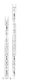
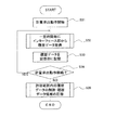
まず、本実施の形態に係る計量包装システムの基本的な構成について、図1を参照して説明する。図1は、本実施の形態に係る計量包装システムの概略構成を示すブロック図である。
(Embodiment 1)
The first embodiment is a “measuring / packaging system according to the present invention”, a monitoring device for the weighing / packaging system according to the present invention, or a basic configuration common to the weighing / packaging apparatus according to the present invention. Reference form ".
[Configuration of weighing packaging system]
First, the basic configuration of the weighing packaging system according to the present embodiment will be described with reference to FIG. FIG. 1 is a block diagram showing a schematic configuration of a weighing packaging system according to the present embodiment.
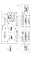
図1に示すように、本実施の形態に係る計量包装システムは、計量機としての組合せ秤10および包装機20を含んでいる。組合せ秤10は、組合せ秤本体部11、組合せ秤制御部12、操作設定表示部13、およびインターフェース部14を備えている。組合せ秤本体部11は、いずれも図示されないが、計量の対象である物品を供給する供給装置と、トップコーンと、トップコーンの下方に配置され、供給された物品を振動動作により分散させるメインフィーダと、複数のリニアフィーダパンと、各リニアフィーダパンに対応して複数設けられ、分散した物品を振動動作により搬送する複数のリニアフィーダと、搬送された物品を纏めて所定のタイミングで供給する複数の供給ホッパと、供給ホッパから供給された物品を収容する複数の計量ホッパと、各計量ホッパに収容された物品の重量を検出する重量検出器と、計量ホッパから物品を受け取って集合させ、下流へと供給する複数の集合シュートと、集合シュートから供給される物品を集めて包装機へと排出する排出シュートと、を備えている。
As shown in FIG. 1, the weighing and packaging system according to the present embodiment includes a
組合せ秤制御部12は、組合せ秤10(組合せ秤本体部11)による組合せ計量動作と計量後の物品の排出動作(以下、まとめて計量排出動作という。)を制御する。具体的には、組合せ秤制御部12は、前記重量検出器で検出された前記複数の前記計量ホッパの前記物品の重量を、所定数の計量ホッパ毎に合計して組合せ重量を生成する。次に、組合せ秤制御部12は、生成した組合せ重量と設定重量とを比較し、前記所定数の計量ホッパの好適な組合せを選択する。次に組合せ秤制御部12は、選択された好適な組合せに参加する計量ホッパから物品を排出させる。排出された物品は集合させられて包装機に排出される。組合せ秤制御部12は、たとえばマイクロコンピュータのCPUで構成される。
The combination
操作設定表示部13は、その操作に応じて、組合せ秤10を操作する操作指定を出力したり、組合せ秤10の計量排出動作に伴う各種パラメータを設定したりするとともに、当該操作や組合せ秤10の動作に伴う各種情報を表示するよう構成されている。具体的には、図1に示すように、タッチパネル部31、操作設定表示制御部32、記憶部33、I/O回路34、大型表示部35、および外部通信部36を備えている。タッチパネル部31は、例えば、カラー液晶表示パネルの表面に貼り付けられて一体化された抵抗膜方式のタッチパネルである。すなわち、タッチパネル部31は、表示器としてカラー液晶表示パネルと、操作器としてのタッチパネルとを備える構成であり、操作器および表示器として機能する。操作器としてのタッチパネル部31は、表示画面で、例えばキー状の表示領域として操作キーを表示する。この操作キーに指先等を接触させることで、タッチパネルの機能によって、組合せ秤10による計量排出動作、操作設定表示部13による情報の表示等についての操作指令が、タッチパネル部31から操作設定表示制御部32に出力される。また、操作設定表示制御部32の制御により、タッチパネル部31の表示画面の切り替え等が可能となっている。
In response to the operation, the operation setting
操作設定表示制御部32は、タッチパネル部31、記憶部33、I/O回路34、大型表示部35、および外部通信部36に接続され、操作器である前記タッチパネルの操作に応じて、タッチパネル部31から、記憶部33、I/O回路34、大型表示部35、および外部通信部36への情報の入出力を制御する。また、本実施の形態では、操作設定表示制御部32は、後述するように、インターフェース部14から当該インターフェース部14で送受信された信号の履歴である通信の履歴データを取得し、記憶部33の不揮発性メモリ33bに記憶させるようになっている、すなわち、操作設定表示制御部32は、操作設定表示部13の動作を制御するだけでなく、インターフェース部14による通信の履歴を履歴データとして取得し、記憶部33に記憶させる通信監視器となっている。操作設定表示制御部32は、たとえばマイクロコンピュータのCPUで構成される。
The operation setting
記憶部33は、例えば、RAM(Random Access Memory)33aおよび不揮発性メモリ33bから構成され、操作設定表示部32の制御により各種情報を記憶する。RAM33aは、例えば演算等のために一時的に情報の記憶し、不揮発性メモリ33bは、操作設定表示制御部32を動作させるためのプログラムや、後述する履歴データ等を記憶する。また、記憶部33は、操作設定表示制御部32の制御により記憶されている各種情報が読み出されるよう構成されている。記憶部33は、マイクロコンピュータの内部メモリで構成されるが、不揮発性メモリ33bは、外部記憶装置で構成されてもよい。
The
I/O回路34は、組合せ秤制御部12に接続され、操作設定表示制御部32からの情報を組合せ秤制御部12に出力し、組合せ秤制御部12からの出力用情報等を操作設定表示制御部32に入力するよう構成される。I/O回路34は、マイクロコンピュータのI/O入出力回路で構成される。
The I /
大型表示部35は、例えば、タッチパネル部31よりも大きな液晶表示パネルであり、操作設定表示制御部32の制御により各種情報を表示画面で表示する。つまり、大型表示部35は、タッチパネル部31とは異なり、表示器のみとして機能する。外部通信部36は、外部装置30との間で情報の送受信を行う通信器であり、図示されないコネクタを介して外部装置30のインターフェースと接続されている。外部通信部36は、操作設定表示制御部32の制御により外部装置30との間で各種情報を送受信するよう構成されている。外部装置30が例えばプリンタであったりパーソナルコンピュータ(PC)であったりすれば、外部通信部36は、通信器としてだけでなく情報の出力器として機能することになる。また、外部装置30が各種情報の入力装置であれば、外部通信部36は入力器としても機能する。外部通信部36としては、例えばLANボードを用いることができる。
The
包装機20は、包装機本体部21、包装機制御部22、操作設定表示部23、およびインターフェース部24を備えている。包装機本体部21は、例えば、公知の縦型ピロー包装機であり、組合せ秤本体部11から排出された、組合せ計量後の物品を袋内に充填して包装する。包装機制御部22は、包装機本体部21による包装動作を制御する。包装機制御部22は、組合せ秤制御部12と同様に、たとえばマイクロコンピュータのCPUで構成される。操作設定表示部23は、その操作に応じて、包装機20を操作する操作指定を出力したり、包装機20の包装動作に伴う各種パラメータを設定したりするとともに、当該操作や包装機20の動作に伴う各種情報を表示するよう構成されている。具体的な構成は、組合せ秤10の操作設定表示部13と同様である。
The
組合せ秤10のインターフェース部14および包装機20のインターフェース部24は、組合せ秤10および包装機20の間で、組合せ秤10の計量排出動作および包装機20の包装動作を連係させる連係用信号を送受信する。つまり、インターフェース部14,24は通信器として機能する。組合せ秤10のインターフェース部14は、組合せ秤制御部12の制御により連係用信号を送受信するよう構成され、包装機20のインターフェース部24は、包装機制御部22の制御により連係用信号を送受信するよう構成されている。具体的な構成としては、組合せ秤10の操作設定表示部13が備える外部通信部36と同様に、LANボード等の公知の通信器を用いてもよいが、計量包装システムとして、計量排出動作および包装動作をより一層連係させるために、設定される連係用信号の種類に対応した配線で接続する構成を挙げることができる。すなわち、本実施の形態では、インターフェース部14,24は、設定される連係用信号のONまたはOFFを配線により送受信する構成であることが好ましい。
The
本実施の形態に係る計量包装システムは、組合せ秤10および包装機20に加えて外部装置30を含んでいる。外部装置30の種類は特に限定されず、外部通信部36に関する前記説明で例示したように、プリンタ、パーソナルコンピュータ(PC)、各種情報の入力装置等が挙げられるが、さらに、計量包装システムを含む生産ライン全体を監視するモニター装置、当該生産ラインに設置される重量選別機等の検査装置も挙げられる。
The weighing and packaging system according to the present embodiment includes an
なお、本実施の形態に係る計量包装システムにおいては、外部装置30は必須の構成ではない。つまり、本実施の形態に係る計量包装システムは、少なくとも組合せ秤10および包装機20からなっていればよい。
In the measurement packaging system according to the present embodiment, the
[計量包装システムの動作]
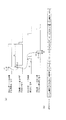
次に、本実施の形態に係る計量包装システムの基本的な動作、すなわち組合せ秤10による計量排出動作、および、包装機20による包装動作、並びに、これら計量排出動作および包装動作の連係について、図1および図2を参照して説明する。図2は、本実施の形態に係る計量包装システムにおいて、組合せ秤10および包装機20の間で送受信される連係用信号のタイミングチャートである。
[Operation of weighing and packaging system]
Next, the basic operation of the weighing and packaging system according to the present embodiment, that is, the weighing and discharging operation by the
本実施の形態では、組合せ秤10の計量排出動作および包装機20の包装動作を連係させる連係用信号として、包装機20から組合せ秤10へ送信される排出要求信号と、組合せ秤10から包装機20へ送信される排出完了信号とが用いられる。
In the present embodiment, a discharge request signal transmitted from the
組合せ秤10では、組合せ秤本体部11において、供給装置からトップコーンへ物品が供給され、所定の時間および強度でメインフィーダが振動する。これにより、トップコーン上の物品は分散され、周囲に配置されるリニアフィーダパンに供給される。また、所定の時間および強度でリニアフィーダが振動する。これにより、リニアフィーダパン上の物品が搬送され、供給ホッパに供給される。次に、供給ホッパから計量ホッパに物品が供給され、各計量ホッパに対応するよう備えられた重量検出器により、当該計量ホッパで計量された物品の重量が検出され、組合せ秤制御部12に出力される。組合せ秤制御部12は、得られた物品の重量を用いて組合せ演算を行い、予め設定された組合せ目標重量(設定重量)に基づいて、最適な計量ホッパの組合せの選定を行う。この時点の組合せ秤10は、計量動作を完了させ、排出動作を待機している状態である。
In the
一方、包装機20では、包装機本体部21において、シート状の包装材が予めロール状に巻かれて準備されている。包装機本体部21では、巻かれた包装材が引き出されてフォーミングチューブに巻き回されることにより、シート状の包装材は筒状に成形される。そして筒状の包装材は、プルダウンベルトにより下方に順次引き出され、当該包装材の重ねられた縦の縁が縦シール機によってシールされる。この時点の包装機20は、組合せ秤10の排出動作を待機している状態である。
On the other hand, in the
包装機20が前記待機状態となれば、包装機制御部22は、インターフェース部24により、図2に示すように、組合せ秤10に対して排出要求信号を送信させる。組合せ秤制御部12は、排出要求信号を受信すれば、組合せ秤本体部11に対して、排出動作を行わせる。すなわち、組合せ秤制御部12は、最適な組合せに参加する計量ホッパから物品を排出させる。排出された物品は、集合シュートにより集合させられ、排出シュートから包装機20に排出される。排出動作が完了した後、組合せ秤制御部12は、インターフェース部14により、図2に示すように、包装機20に対して排出完了信号を送信させる。
When the
その後、包装機20では、組合せ秤本体部11の排出シュートから排出された物品が、包装機本体部21のファネルに落下し、フォーミングチューブ内を通過して筒状の包装材内に充填される。そして、フォーミングチューブの下方に配置される横シール機により横方向にシールされる。この横方向のシールは、先行する袋の上端とその後に続く筒状の包装材の下端とにまたがって行われる。したがって、先行する袋は、前回での横方向のシールにより下端が封止された状態で、上端がさらに封止されるため、上下がシールされた完全な袋となる。そして、横シール機に内蔵されているカッターにより横方向のシール部分の中央が切断される。これにより、先行する袋と後続する袋とが分離される。この時点の包装機20は、1回の包装動作を完了させた状態であると同時に、組合せ秤10の次の排出動作を待機している状態に戻ることになる。
Thereafter, in the
ここで、組合せ秤10では、最適な計量ホッパの組合せが選定されても、包装機20で排出された物品を受け入れる体制となっていなければ排出動作を行うことはできない。一方、包装機20では、少なくとも、先行する袋の上端が横方向にシールされた時点で、組合せ秤10から物品の排出を受け入れることが可能となる。それゆえ、組合せ秤10による排出動作のタイミングと、包装機20による排出受け入れの準備完了のタイミングとを、可能な限り時間のロスが生じないように合わせることで、計量排出動作と包装動作との好適な連係を実現することができる。なお、以下の説明では、連携する計量排出動作および包装動作を「計量包装動作」という。
Here, in the
一般的な計量包装システムでは、計量機と包装機との間で送受信される連係用信号は、排出要求信号および排出完了信号である。本実施の形態でも、図2に示すように、連係用信号として排出要求信号および排出完了信号が送受信される。そこで、組合せ秤10が包装機20から受信する排出要求信号の受信時間をt2とし、排出要求信号の送信後に組合せ秤10から包装機20に対して排出完了信号が送信されるまでの間隔をt3とし、包装機20から組合せ秤10が包装機20から受信する排出要求信号の受信間隔をt6とすれば、これらt2、t3およびt6をタイミング設定時間として、物品の種類等に応じて理想的な値(理想値)を設定する。これによって、計量排出動作および包装動作のタイミングを好適に合わせることが可能となるだけでなく、本発明では、これらタイミング設定時間の測定値を履歴データとして取得することで、計量包装システムの不具合を検証する。
In a general weighing and packaging system, linkage signals transmitted and received between the weighing machine and the packaging machine are a discharge request signal and a discharge completion signal. Also in this embodiment, as shown in FIG. 2, a discharge request signal and a discharge completion signal are transmitted and received as linkage signals. Therefore, the reception time of the discharge request signal received by the
すなわち、前記タイミング設定時間について理想値を設定すれば、計量排出動作と包装動作とを良好に連係させることができる。しかしながら、なんらかの原因で適切な連係が行われず、その結果として、1日数回程度の頻度で包装に不具合が生じる。例えば、計量包装システムによる包装物の生産量が60パック/分であれば、計量包装システムを8時間稼動させれば、1日の生産量は約3万パックとなる。ここで、1日数回しか発生しない前期不具合をオペレーターが目視で確認することは不可能である。また、前記不具合の原因は、多くの場合、特定の条件が揃ったときに生じるソフトウエアのバグか、電気的ノイズによる撹乱であるが、その原因を特定することは難しい。 That is, if an ideal value is set for the timing setting time, the weighing and discharging operation and the packaging operation can be linked well. However, proper linkage is not performed for some reason, and as a result, defects occur in the packaging several times a day. For example, if the production amount of the package by the weighing and packaging system is 60 packs / minute, if the weighing and packaging system is operated for 8 hours, the daily production amount is about 30,000 packs. Here, it is impossible for the operator to visually confirm the previous malfunction that occurs only several times a day. In many cases, the cause of the malfunction is a software bug that occurs when specific conditions are met, or disturbance caused by electrical noise, but it is difficult to identify the cause.
本実施の形態では、組合せ秤10のインターフェース部14で送受信された連係用信号の履歴を、履歴データとして記憶させる(ロギングを行う)。このとき、履歴データとしては、前記タイミング設定時間の測定値を少なくとも取得する。これにより、不具合の発生時には、インターフェース部14の通信ログから、不具合の発生時期に相当する履歴データのファイルを取得することが可能となり、取得したファイルに含まれる前記タイミング設定時間の測定値から、不具合の発生の原因を検証することができる。
In the present embodiment, the history of linkage signals transmitted and received by the
例えば、組合せ秤10が包装機20から排出要求信号を受信していないにも関わらず、組合せ秤10から包装機20へ排出完了信号を送信していれば、組合せ秤制御部12を動作させるソフトウエアにバグが含まれ、包装機20において空袋の不具合が発生することが想定される。この事例では、タイミング設定時間t2およびt3から不具合の検証が可能である。あるいは、組合せ秤10が包装機20から排出要求信号を1回受信した場合に、組合せ秤10から包装機20に対して排出完了信号が2回以上送信されていれば、組合せ秤制御部12を動作させるソフトウエアにバグが含まれ、包装機20においてダブルバッグが発生することが想定される。この事例でも、タイミング設定時間t2およびt3から不具合の検証が可能である。
For example, if the
また、包装機20は、当該包装機20の包装能力を超える頻度で組合せ秤10に対して排出要求信号を送信することはない。したがって、組合せ秤10における排出要求信号の受信の間隔は、通常よりも短い間隔で発信されないはずである。したがって、組合せ秤10が、通常よりも短い間隔で排出要求信号を受信していれば、電気的ノイズの発生により排出要求信号の受信間隔やその受信時間も通常と異なる値となることが想定される。この事例では、タイミング設定時間t6およびt2から不具合の検証が可能である。
Further, the
[履歴データの構成]
次に、本実施の形態に係る計量包装システムにおいて、組合せ秤10と包装機20との間で送受信される連係用信号について、図3(a),(b)を参照して説明する。図3(a)は、図2に示すタイミングチャートに対応する履歴データの正常な構成を示す図であり、図3(b)は、図3(a)に示す履歴データの異常な構成を示す図である。
[Configuration of historical data]
Next, in the weighing and packaging system according to the present embodiment, an association signal transmitted and received between the
通信のロギングは、1回の計量包装動作毎に1ファイルの履歴データとして取得され、記憶部33(不揮発性メモリ33b)に通信ログとして記憶される。前記履歴データの1ファイルは、例えば本実施の形態では、図3(a)に示すように、データ開始から品種番号、通信年月日、通信時刻、計量情報、タイミング設定時間t2の測定値、タイミング設定時間t3の測定値、およびタイミング設定時間t6の測定値の順で配列する構成となっている。
The communication logging is acquired as history data of one file for each weighing and packaging operation, and stored as a communication log in the storage unit 33 (
図3(a)における「STX」は、履歴データ1ファイルのヘッダーであり、1回の計量包装動作に伴って送受信される連係用信号の履歴の開始を示す。「ETX」は、履歴データ1ファイルのファイルエンド(EOF)であり、1回の計量包装動作に伴って送受信される連係用信号の履歴の終了を示す。
“STX” in FIG. 3A is a header of the
品種番号は、組合せ秤10で計量排出した物品の種類を示すデータであり、包装機20で包装した物品の種類を示すデータでもある。通常、同一の品種番号の物品であれば、前記タイミング設定時間も同一であるため、前記通信ログから特定のファイルの検索するときに、重要な検索条件となる。なお、履歴データには、計量または包装した物品の種類が識別できるデータ(以下、品種データという。)が含まれていれば、必ずしも前記品種番号でなくてもよく、例えば、品種の名称やその略号等であってもよい。この品種番号は、組合せ秤制御部11から取得する。
The product type number is data indicating the type of the article weighed and discharged by the
通信年月日および通信時刻は、当該ファイルに対応する連係用信号が送受信された日付および時刻を示すデータである。この日付データは、前記通信ログから、不具合の発生時期に相当するファイルを取得するために必要なデータである。この通信年月日および通信時刻をまとめて日付データとする。この日付データは、インターフェース部14から取得する。
The communication date and communication time are data indicating the date and time when the link signal corresponding to the file is transmitted and received. This date data is data necessary for obtaining a file corresponding to the time of occurrence of the defect from the communication log. The communication date and communication time are collectively used as date data. This date data is acquired from the
計量情報は、計量排包装動作の制御に伴い毎回の動作で決定されるパラメータ(以下、動作制御データという。)である。計量情報の具体的な種類は特に限定されないが、本実施の形態では、前述した組合せ秤本体部11の構成および組合せ計量制御に基づき、組合せ重量、組合せ計量制御に参加した制御参加計量ホッパ数、選択された好適な組合せに参加した選択計量ホッパ数、およびメインフィーダによる物品の分散レベルの少なくともいずれかのパラメータであればよい。この動作制御データは、組合せ秤制御部11から取得する。
The weighing information is a parameter (hereinafter referred to as operation control data) determined by each operation in accordance with the control of the weighing and discharging operation. Although the specific type of the weighing information is not particularly limited, in the present embodiment, based on the configuration of the combination weigher
t2、t3およびt6は、前述したタイミング設定時間である。図3(a)は、正常なファイル、すなわち、通常の計量包装動作で取得される履歴データであるため、その測定値は理想値に合致しており、それぞれt2=150ms、t3=300ms、t6=800msとなっている。これらタイミング設定時間の具体的な種類は、これらt2、t3、またはt6に限定されず、インターフェース部14で連係用信号の送受信が行われている時間(以下、通信時間データという。)と、インターフェース部14での連係用信号が送受信される間隔(以下、通信間隔データという。)とであればよい。タイミング設定時間の他の例については、実施の形態2で説明する。これらタイミング設定時間はインターフェース部14から取得する。
t2, t3, and t6 are the timing setting times described above. FIG. 3A is a normal file, that is, history data acquired in a normal weighing and packaging operation, and therefore the measured values match the ideal values, and t2 = 150 ms, t3 = 300 ms, and t6, respectively. = 800 ms. The specific types of these timing setting times are not limited to these t2, t3, or t6, and the time during which the link signal is transmitted and received by the interface unit 14 (hereinafter referred to as communication time data), and the interface. The interval at which the signal for linking in the
図3(a)に示す構成の前記履歴データのファイルは正常なファイルであるが、異常の発生した履歴データは、例えば、図3(b)に示すように、タイミング設定時間の測定値が正常な履歴データと異なっている。具体的には、ヘッダーからt2の測定値までは正常なファイルと同一であるが、t2の測定値の次にt3の測定値が配列しておらず、t6の測定値が配列している。すなわち、前記異常なファイルを正常なファイルと比較すれば、組合せ秤10が包装機20から排出要求信号を受信するまでは正常であったが、その後、組合せ秤10から包装機20に対して排出完了信号が送信するまでの間隔が記憶されていないことがわかる。しかも、t6=200msであるので、先行する排出要求信号の受信から次の排出要求信号の受信までの間隔は、理想値の800msより短くなっていることがわかる。
The history data file having the configuration shown in FIG. 3A is a normal file, but the history data in which an abnormality has occurred has a normal measurement value of the timing setting time as shown in FIG. 3B, for example. Different from historical data. Specifically, the measurement value from the header to the measurement value of t2 is the same as the normal file, but the measurement value of t3 is not arranged next to the measurement value of t2, and the measurement value of t6 is arranged. That is, if the abnormal file is compared with a normal file, it was normal until the
さらに、図2のタイミングチャートから明らかなように、タイミング設定時間t2、t3およびt6は、1回の計量包装動作でいずれもこの順で1回しか取得されないはずであるが、異常なファイルでは、t6の後にt2、t3およびt6が余計に取得されている。2回目のt2=20ms、2回目のt6=600msであることから、いずれも理想値より短い時間となっている。この異常なファイルの構成から、組合せ秤10は、包装機20から排出要求信号を正常に受信したものの、包装機20に対して排出完了信号を送信しておらず、その後、本来不要な2回目の排出要求信号を理想値よりも短い時間で受信し、その後に正常な排出完了信号が包装機20に送信されたことがわかる。
Further, as apparent from the timing chart of FIG. 2, the timing setting times t2, t3 and t6 should be obtained only once in this order in one weighing and packaging operation, but in an abnormal file, After t6, t2, t3, and t6 are acquired. Since the second t2 = 20 ms and the second t6 = 600 ms, both times are shorter than the ideal values. Due to this abnormal file configuration, the
前記異常なファイルの事例では、t3の測定値が正常に取得されていないことから、組合せ秤10から包装機20に排出完了信号が送信されていないことがわかる。そして、この異常なファイルに対応する不具合が、たとえばダブルバッグ(1つの包装袋内に2つ分の物品が入る不具合)であれば、ダブルバッグの原因は、組合せ秤10から排出完了信号が適切に送信されなかったことにより、包装機20から2回目の排出要求信号が送信されたことにあると判断できる。このように、本発明では、少なくともタイミング設定時間を確認することで、不具合の原因を探ることが可能となる。
In the case of the abnormal file, since the measured value of t3 is not normally acquired, it is understood that the discharge completion signal is not transmitted from the
しかも、本実施の形態では、組合せ秤10のインターフェース部14のみについて、履歴データのロギングを行っている。したがって、計量包装システムを構成する組合せ秤10および包装機20のうち、一方の処理装置である組合せ秤10について履歴データをロギングするだけで、計量包装システム全体の不具合の原因を検討することが可能となる。それゆえ、包装の不具合の原因が計量機または包装機のいずれに由来するのかを、適切かつ容易に確認することができる。さらに、前記履歴データには前記動作制御データも含まれるため、不具合の発生時には組合せ秤10の動作状況も参照することができる。それゆえ、不具合の原因の検証をより厳密に行うことができる。
Moreover, in the present embodiment, history data is logged only for the
[履歴データの取得と記憶]
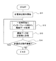
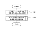
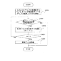
本実施の形態では、前記各データを含む履歴データの取得と記憶(ロギング)は、組合せ秤10の操作設定表示制御部32により通信監視制御として行われる。このロギングの制御について、図1、図4および図5を参照して説明する。図4は、組合せ秤10が備える操作設定表示制御部32が行う、インターフェース部14からの履歴データの取得および記憶の制御を示すフローチャートである。図5は、組合せ秤制御部12が行うインターフェース部14での通信制御の一例を示すフローチャートである。
[Acquisition and storage of historical data]
In the present embodiment, acquisition and storage (logging) of history data including each data is performed as communication monitoring control by the operation setting
まず、操作設定表示制御部32は、組合せ秤制御部12から取得した情報に基づき、組合せ秤本体部11で計量排出動作が開始されたことを確認すると(ステップS11)、一定時間毎に、インターフェース部14から履歴データを取得し(ステップS12)、記憶部33に記憶させる(ステップS13)。その後、組合せ秤制御部12から取得した情報に基づき、計量排出動作が継続しているか否かを判定する(ステップS14)。継続していれば(ステップS14でYES)、ステップS12に戻り、履歴データの取得と記憶とを繰り返すが、継続していなければ(ステップS14でNO)、通信監視制御を終了する。
First, when the operation setting
ここで、ステップS12において、履歴データを取得する具体的な方法は限定されないが、例えば、タイミング設定時間の測定値を取得する方法としては、インターフェース部14における連係用信号の送受信を定期的に行うよう制御する構成を挙げることができる。この方法は、一定時間内に信号を受信するか否かによって通信できているか否かを判定する処理として、従来から広く行われている(例えば、特許文献3)。この方法を利用することで、操作設定表示制御部32は、履歴データのうち、タイミング設定時間の測定値を容易に取得することができる。
Here, in step S12, the specific method for acquiring the history data is not limited. For example, as a method for acquiring the measurement value of the timing setting time, the
具体的には、図5に示すように、組合せ秤制御部12は、インターフェース部14で包装機20から受信した連係用信号を読み込む制御を行い(ステップS1201)、次に、インターフェース部14から包装機20へ連係用信号を送信する制御を行う(ステップS1202)。この2段階の制御を一定時間毎で起動するように設定しておけば、操作設定表示制御部32は、インターフェース部14における連係用信号の送受信を定期的にモニターすることで、当該連係用信号の送受信が行われている時間および送受信の間隔を測定することができる。前記一定時間としては、例えば10msを挙げることができる。なお、不具合の原因をより詳細に検討するためには、できるだけ細かい時間単位でタイミング設定時間の測定値を取得することが好ましいが、時間単位が細かすぎるとデータ量が増大するため、データの記憶、データの検索または呼び出し等に工夫を要する。したがって、前記一定時間としては、1回の計量包装動作に要する時間や、送受信される連係用信号の時間または間隔等に応じて適切な時間を設定すればよい。
Specifically, as shown in FIG. 5, the
また、品種番号および計量情報は、組合せ秤本体部11の計量排出動作の制御に付随するデータである。それゆえ、操作設定表示制御部32は、計量排出動作の制御を司る組合せ秤制御部12から、公知の制御方法で取得するよう構成されればよい。
The product number and the weighing information are data accompanying control of the weighing and discharging operation of the combination weigher
[履歴データの呼び出しと出力]
次に、記憶部33に記憶された通信ログから、特定のファイルを呼び出し、出力する制御について、図6を参照して説明する。図6は、本実施の形態に係る計量包装システムにおいて、計量包装動作に不具合が発生したときに、当該不具合の発生時期に対応する履歴データのファイルを呼び出して出力する制御を示すフローチャートである。
[Recall and output history data]
Next, control for calling and outputting a specific file from the communication log stored in the
まず、包装機20の包装動作に不具合が発生した場合、オペレーターは、操作器であるタッチパネル部31から、不具合に対応する履歴データのファイルを呼び出すよう操作指令を入力する(ステップS21)。例えば、空袋やダブルバッグ等の不具合が発生した年月日と時刻が判れば、その年月日および時刻をタッチパネル部31から入力する。次に、操作設定表示制御部32は、入力された操作指令に基づき、記憶部33に記憶される通信ログから、不具合に対応するファイル(以下、不具合ファイルという。)を呼び出す(ステップS22)。例えば、ステップS21で、呼び出し条件として不具合の発生日時が入力されれば、操作設定表示制御部32は、通信ログから、対応する履歴データのファイルを検索し呼び出す。
First, when a malfunction occurs in the packaging operation of the
次に、操作設定表示制御部32は、呼び出された不具合ファイルから出力用情報を生成し(ステップS23)、各種出力装置により不具合ファイルを出力させる(ステップS24)。前記出力装置としては、操作設定表示部13が備える大型表示部35あるいはタッチパネル部31等のような表示器、各種プリンタ等の印刷器、あるいは、操作設定表示部13が備える外部通信部36等が挙げられるが特に限定されない。ステップS22の検索により複数の候補が選択される場合には、大型表示部35等で検索結果を表示するよう構成すればよい。
Next, the operation setting
また、表示された候補の中から、最も不具合に対応するファイルであると判断されたものを、外部装置30としてのプリンタ等で印刷するように構成してもよい。さらに、外部装置30として例示したパーソナルコンピュータ(PC)、モニター装置等に対して履歴データを通信するよう構成してもよい。
Further, it may be configured such that, from among the displayed candidates, a file determined to be the file corresponding to the most trouble is printed by a printer or the like as the
不具合ファイルの具体的な表示方法についても特に限定されないが、例えば、図2に示すようなタイミングチャートとして表示してもよいし、図3(a),(b)に示すようなデータ配列として表示してもよいし、各種データを数値として表示してもよい。図2に示すタイミングチャートは、オシロスコープを用いた場合と同様の表示となるので、ファイル表示の目的がオシロスコープを用いた通信のモニタリングと同様であれば、この表示を用いることが好ましい。また、図3(a),(b)に示すデータ配列であれば、前記のとおり、タイミング設定時間の測定値に異常が発生した場合には、一目瞭然で異常が判断できるため好ましい。あるいは、数値の表示では、複数のファイルを一覧表等として表示することで、他のファイルと比較しやすくなるため好ましい。 The specific display method of the defect file is not particularly limited. For example, it may be displayed as a timing chart as shown in FIG. 2 or as a data array as shown in FIGS. 3 (a) and 3 (b). Alternatively, various data may be displayed as numerical values. Since the timing chart shown in FIG. 2 is the same display as when an oscilloscope is used, this display is preferably used when the purpose of file display is the same as that of communication monitoring using an oscilloscope. The data arrangement shown in FIGS. 3A and 3B is preferable because, as described above, if an abnormality occurs in the measured value of the timing setting time, the abnormality can be determined at a glance. Alternatively, it is preferable to display a numerical value because a plurality of files are displayed as a list or the like so that it can be easily compared with other files.
前記ステップS22では、通信ログから条件に合致するファイルを検索する例を挙げたが、必ずしもこの例に限定されず、特定のファイルを呼び出すような構成であってもよい。 In step S22, an example of searching for a file that matches a condition from the communication log has been described. However, the present invention is not necessarily limited to this example, and a configuration in which a specific file is called may be used.
このように、本実施の形態によれば、組合せ秤10のインターフェース部14について通信を監視するのみで、組合せ秤10および包装機20の間での通信を監視することになる。それゆえ、オシロスコープのような特別な監視装置を用いて組合せ秤10および包装機20の双方の通信を監視しなくてよい。計量包装システムの多くは、組合せ秤10と包装機20とは、他の処理装置を介さないことを前提に接続されているため、オシロスコープのような特別な監視装置を接続することは煩雑であるか困難である。しかしながら、本実施の形態によれば、特別な監視装置を設けずに通信の履歴を蓄積することができる。
Thus, according to the present embodiment, only communication between the
しかも、履歴データとして、通信の状況だけでなく通信の日付と計量排出動作または包装動作の対象となる物品の種類も取得しているので、包装等に低頻度の不具合が生じた場合であっても、その原因が計量機または包装機のいずれにあるのかを検証するために、通信ログから対応する履歴データのファイルを呼び出して参照することができる。また、組合せ秤10の内部で通信状況をロギングするという簡素な処理を行うのみでよいため、複雑な構成の通信監視器を用いる必要がなく、ソフトウエアを用いた制御で対応が可能となる。
In addition, as the history data, not only the communication status but also the date of communication and the type of article subject to the weighing discharge operation or the packaging operation are acquired, so there is a case where infrequent defects occur in packaging etc. In addition, in order to verify whether the cause is the weighing machine or the packaging machine, a corresponding history data file can be called up and referred to from the communication log. Further, since it is only necessary to perform a simple process of logging the communication status inside the
[変形例]
本実施の形態では、操作設定表示制御部32が通信監視器として動作するよう構成されている。操作設定表示制御部32としては前述のとおりCPUを用いることができるので、CPUを前記通信監視器として動作させるプログラムを記憶部33に格納しておけばよい。これにより、別途特別の通信監視器を設ける必要がなくなる。しかしながら、本発明は前記構成に限定されず、操作設定表示制御部32とは別に通信監視部が設けられてもよい。
[Modification]
In the present embodiment, the operation setting
例えば、通信監視部は、組合せ秤制御部12の機能構成であって、組合せ秤制御部12に含まれる演算部としてのCPUが、組合せ秤制御部12に含まれる記憶部に格納されるプログラムに従って動作することにより実現される構成であってもよい。ただし、通信のロギングや通信ログからのファイルの呼び出しは、組合せ秤本体部11の計量排出動作との関係性は低いので、本実施の形態のように、操作や表示を司る操作設定表示制御部32を通信監視器として動作させることで、効率的な制御が可能となる。
For example, the communication monitoring unit is a functional configuration of the combination
また、本実施の形態では、履歴データとして取得する具体的なデータは、(1)インターフェース部14で連係用信号を送受信した年月日および時刻(日付データ)、(2)インターフェース部14で連係用信号の送受信が行われている時間(通信時間データ)、(3)インターフェース部14での連係用信号が送受信される間隔(通信間隔データ)、(4)計量または包装した前記物品の種類(品種データ)、および(5)計量排包装動作の制御に伴い、毎回の動作で決定されるパラメータ(動作制御データ)の5種類であるが、本発明はこれに限定されず、少なくとも(1)〜(4)のデータを取得すれば、不具合の原因を探ることが可能となる。
In the present embodiment, the specific data acquired as history data includes (1) the date and time (date data) when the
前記データのうち(1)および(4)は、通信ログからのファイルの呼び出しや検索において重要なデータであり、(2)および(3)は前記タイミング設定時間であるので、不具合の原因を判断する基本データとなる。一方、(5)は、組合せ秤10の計量排出動作におけるパラメータであるので、不具合の発生の原因が組合せ秤10にある場合に特に有効なデータである。ただし、前記タイミング設定時間に異常が見られない場合には、より詳細な検討が必要となるので、この場合には、(5)のデータを取得するよう構成していることが特に好ましい。不具合の原因を検証するためには、取得するデータの種類は多く、データの分解能も高いことが好ましいためである。
Among the data, (1) and (4) are important data for file call and search from the communication log, and (2) and (3) are the timing setting time, so the cause of the failure is determined. Basic data to be used. On the other hand, since (5) is a parameter in the weighing and discharging operation of the
さらに、本実施の形態では、計量包装システムが、組合せ秤10および包装機20、並びに必要に応じて外部装置30からなっているが、これに限定されず、組合せ秤10以外の公知の計量機を用いることもできる。また、外部装置30は1台のみでもよいし、複数台含まれていてもよい。
Furthermore, in this embodiment, the weighing and packaging system includes the
(実施の形態2)
本実施の形態では、計量包装システムの構成は前記実施の形態1と同じであるが、組合せ秤10と包装機20との間で送受信される連係用信号の種類および履歴データとして取得されるデータの種類もより多くなっており、通信のロギングや通信ログからのファイルの呼び出しに関する制御も異なっている。
(Embodiment 2)
In the present embodiment, the configuration of the weighing and packaging system is the same as that of the first embodiment, but the types of linkage signals transmitted and received between the
[履歴データの構成]
本実施の形態に係る計量包装システムにおいて前記連係用信号について、図7(a),(b)を参照して説明する。図7(a)は、本実施の形態に係る計量包装システムにおいて、組合せ秤10および包装機20の間で送受信される連係用信号のタイミングチャートであり、図7(b)は、図7(a)に示すタイミングチャートに対応する履歴データの構成を示す図である。
[Configuration of historical data]
In the weighing packaging system according to the present embodiment, the linkage signal will be described with reference to FIGS. 7 (a) and 7 (b). FIG. 7A is a timing chart of an association signal transmitted and received between the
前記実施の形態1では、組合せ秤10のインターフェース部14で送受信される連係用信号は、包装機20から送信される排出要求信号、および、組合せ秤10から送信される排出完了信号であったが、本実施の形態では、前記排出要求信号および排出完了信号に加えて、組合せ秤10から送信される排出準備完了信号、および、包装機20から送信される排出信号受取完了信号が、連係用信号として送受信される。
In the first embodiment, the linkage signals transmitted and received by the
前記実施の形態1で説明したように、組合せ秤10は、組合せ秤本体部11において組合せ計量制御を行った時点では、計量動作を完了させ、排出動作を待機している状態にある。ここで、組合せ秤制御部12は、図7(a)の最上段に示すように、インターフェース部14により、包装機20に対して排出準備完了信号を送信させる。計量準備完了信号は、計量機ready信号とも称され、包装機20から組合せ秤10への排出要求信号を送信するインターロック信号となっている。つまり、組合せ秤10からの排出準備完了信号を包装機20が受信しない限り、包装機20は組合せ秤10に対して排出要求信号を送信しない。
As described in the first embodiment, the
包装機20では、排出準備完了信号を組合せ秤10から受信すれば、包装機制御部22は、インターフェース部24により、図7(a)の第二段に示すように、組合せ秤10に対して排出要求信号を送信させる。組合せ秤制御部12は、排出要求信号を受信すれば、組合せ秤本体部11に対して、排出動作を行わせる。排出動作が完了した後、組合せ秤制御部12は、インターフェース部14により、図7(a)の第三段に示すように、包装機20に対して排出完了信号を送信させる。
In the
ここで、包装機制御部22は、組合せ秤10からの排出完了信号を受信すれば、インターフェース部24により、図7(a)の最下段に示すように、組合せ秤10に対して排出信号受取完了信号を送信させる。この排出信号受取完了信号は、組合せ秤10および包装機20のインターロックに用いられる信号ではないが、組合せ秤10および包装機20の動作の連係に不具合が生じた場合、その原因を検証するための信号として包装機20側で準備する。また、この信号は、組合せ秤10から排出完了信号を受信しない限り、包装機20から送信されない。したがって、本実施の形態では、排出信号受取完了信号も連係用信号として用いられる。その後、包装機20では、前記実施の形態1で説明したように、横方向のシールおよびシール部分の切断により、1回の包装動作が完了すると同時に、組合せ秤10の次の排出準備完了信号の受信を待機する状態に戻る。
Here, when the packaging
本実施の形態では、タイミング設定時間として、前記排出要求信号の受信時間t2、排出要求信号の受信後に排出完了信号が送信されるまでの間隔t3、および排出要求信号の受信間隔t6に加えて、図7(a)に示すように、組合せ秤10が包装機20へ排出準備完了信号を送信する送信時間t1、組合せ秤10から包装機20へ排出完了信号が送信されてから組合せ秤10が包装機20から排出信号受取完了信号を受信するまでの間隔t4、および、組合せ秤10が受信する排出信号受取完了信号の受信時間t5についても、これらの測定値を履歴データとして取得する。
In the present embodiment, as the timing setting time, in addition to the discharge request signal reception time t2, the interval t3 until the discharge completion signal is transmitted after receiving the discharge request signal, and the discharge request signal reception interval t6, As shown in FIG. 7A, the
このように、連係用信号として、排出要求信号、排出完了信号、排出準備完了信号、排出信号受取完了信号の4種類を用い、タイミング設定時間として、t1〜t6の6種類を取得するよう構成することで、不具合の発生の原因をより詳細に検証することができる。 As described above, four types of the discharge request signal, the discharge completion signal, the discharge preparation completion signal, and the discharge signal reception completion signal are used as the linking signals, and six types t1 to t6 are acquired as the timing setting time. Thus, the cause of the occurrence of the defect can be verified in more detail.
例えば、組合せ秤10から包装機20に排出準備完了信号を送信していないにも関わらず、組合せ秤10が包装機20から排出要求信号を受信した場合、包装機制御部22を動作させるソフトウエアにバグが含まれるか、信号の送受信ラインに何らかのノイズが伝播したことが想定される。ノイズの伝播か否かについては、排出要求信号の受信時間を観察することで、ある程度判断可能である。この事例では、タイミング設定時間t1およびt2から不具合の検証が可能である。
For example, software that operates the packaging
また、組合せ秤10から包装機20に対して排出完了信号が送信されていないにも関わらず、組合せ秤10が包装機20から排出信号受取完了信号を受信した場合には、信号の送受信ラインに何らかのノイズが伝播したことが想定される。この事例では、タイミング設定時間t4およびt5から不具合の検証が可能である。
Further, when the
本実施の形態で通信ログとして記憶される、履歴データの1ファイルは、例えば、図7(b)に示すように、データ開始から品種番号、通信年月日、通信時刻、計量情報、タイミング設定時間t1〜t6の測定値の順で配列する構成となっている。ファイルを構成する各データの具体的説明は前記実施の形態1と同様であるため省略する。なお、図7(b)に示すファイルは正常なファイルであるため、タイミング設定時間の測定値は理想値に合致しており、それぞれt1=340ms、t2=150ms、t3=300ms、
t4=200ms、t5=140ms、t6=800msとなっている。
One file of history data stored as a communication log in the present embodiment is, for example, as shown in FIG. 7B, from the start of the product type number, communication date, communication time, measurement information, timing setting The arrangement is in the order of the measured values at times t1 to t6. Since the specific description of each data constituting the file is the same as that of the first embodiment, a description thereof will be omitted. Since the file shown in FIG. 7B is a normal file, the measured value of the timing setting time matches the ideal value, and t1 = 340 ms, t2 = 150 ms, t3 = 300 ms,
t4 = 200 ms, t5 = 140 ms, and t6 = 800 ms.
[履歴データの取得と記憶]
次に、前記タイミング設定時間t1〜t6を含む履歴データの取得と記憶(ロギング)の制御について、図8を参照して説明する。図8は、操作設定表示制御部23が行う、インターフェース部14からの履歴データの取得および記憶の制御を示すフローチャートである。
[Acquisition and storage of historical data]
Next, the acquisition and storage (logging) control of history data including the timing setting times t1 to t6 will be described with reference to FIG. FIG. 8 is a flowchart showing control of acquisition and storage of history data from the
本実施の形態では、組合せ秤10および包装機20との間で送受信される連係用信号の種類も、タイミング設定時間の測定値として取得されるデータの種類も、前記実施の形態1と比較して増加している。しかも、例えば1日で約3万パックの生産量に対応する履歴データを全て保存するのであれば、記憶部33の不揮発性メモリ33bが大容量であったとしても、不揮発性メモリ33bは短期間で限界に達してしまう。
In the present embodiment, the types of linkage signals transmitted and received between the
そこで、本実施の形態では、履歴データのうち、不具合の原因の検証に用いるために必要なタイミング設定時間の測定値について、許容範囲を予め設定しておき、この許容範囲内にある測定値を含むファイルについては削除する。つまり、許容範囲内の履歴データは正常な通信についての履歴であると判定できるので、正常な通信に関する履歴データを削除することになる。それゆえ、記憶部33の記憶容量を節約し、より長期間の履歴データを保存することができる。
Therefore, in the present embodiment, an allowable range is set in advance for the measurement value of the timing setting time necessary for use in verification of the cause of the failure in the history data, and the measurement value within this allowable range is set. Delete the included files. In other words, since the history data within the allowable range can be determined as the history for normal communication, the history data regarding normal communication is deleted. Therefore, the storage capacity of the
図8に示すように、本実施の形態における履歴データの取得および記憶の制御は、前記実施の形態1と基本的に同様であるが、前記のとおり、正常な履歴データを削除し、さらに記憶領域の履歴データ領域を圧縮する処理を含んでいる。なお、ここでいう記憶領域の圧縮とは、履歴データのファイルが消去された領域を、次のファイルをシフトさせることで埋めていくことを指す。 As shown in FIG. 8, the control of acquisition and storage of history data in the present embodiment is basically the same as in the first embodiment, but as described above, normal history data is deleted and further stored. The process includes compressing the history data area. Here, the compression of the storage area refers to filling the area where the history data file is erased by shifting the next file.
まず、操作設定表示制御部32は、組合せ秤制御部12から取得した情報に基づき、組合せ秤本体部11で計量排出動作が開始されたことを確認すると(ステップS31)、一定時間毎に、インターフェース部14から履歴データを取得し(ステップS32)、記憶部33に記憶させる(ステップS33)。その後、組合せ秤制御部12から取得した情報に基づき、計量排出動作が継続しているか否かを判定する(ステップS34)。継続していれば(ステップS34でYES)、ステップS32に戻り、履歴データの取得と記憶とを繰り返すが、継続していなければ(ステップS34でNO)、許容範囲内の履歴データを削除し、記憶部33における履歴データ領域を圧縮し(ステップS35)、通信監視制御を終了する。
First, when the operation setting
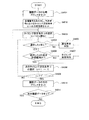
前記ステップS35において行われる処理について、図9を参照して説明する。図9は、図8に示す制御において、許容範囲内の履歴データの削除および履歴データ領域の圧縮の制御を示すフローチャートである。 The process performed in step S35 will be described with reference to FIG. FIG. 9 is a flowchart showing control of deletion of history data within the allowable range and compression of the history data area in the control shown in FIG.
まず、操作設定表示制御部32は、不揮発性メモリ33bの履歴データの記憶領域のうち、圧縮されていない領域の履歴データのファイルの初期アドレスをセットする(ステップS3501)。次に、操作設定表示制御部32は、初期アドレスがセットされた履歴データのファイルから品種番号を読み出すとともに、品種番号毎に設定されているタイミング設定時間t1〜t6の理想値をセットする(ステップS3502)。次に、操作設定表示制御部32は、タイミング設定時間が理想値に対する許容範囲内か判定し、許容範囲内であれば、該当するファイルは正常であると判定して記憶領域から消去する(ステップS3503)。なお、本ステップの処理の詳細については、後述する。
First, the operation setting
操作設定表示制御部32は、圧縮されていない領域の次の履歴データのファイルについて初期アドレスをセットする(ステップS3504)が、このとき、次の履歴データのファイルが存在するか否か判定する(ステップS3505)。存在していれば(ステップS3505でYES)、当該履歴データの品種番号が、先にセットされた履歴データのファイルに含まれる品種番号と一致するか否かを判定する(ステップS3506)。一致していなければ(ステップS3506でNO)、前記ステップS3502と同様に、品種番号毎に設定されているタイミング設定時間t1〜t6の理想値を、異なる品種番号に合わせてセットする(ステップS3507)。一方、品種番号が一致していれば(ステップS3506でYES)、ステップS3507をスキップして、次のステップに進む。
The operation setting
ステップS3507でタイミング設定時間t1〜t6の理想値をセットした後、または、ステップS3506でYESであれば、前記ステップS3503と同様に、操作設定表示制御部32は、タイミング設定時間が理想値に対する許容範囲内か判定し、許容範囲内であれば、該当する履歴データのファイルは正常であると判定して記憶領域から消去する(ステップS3508)。消去が完了すれば、ステップS3504に戻り、次の履歴データのファイルが無くなるまでステップS3504からステップS3508を繰り返す。
After setting the ideal values of the timing setting times t1 to t6 in step S3507, or if YES in step S3506, the operation setting
ステップS3505で、次の履歴データのファイルが存在しなければ(ステップS3505でNO)、消去可能な履歴データが存在しないことになる。そこで、ステップS3509に進み、不揮発性メモリ33bの履歴データの記憶領域を圧縮し、制御を終了する。
If the next history data file does not exist in step S3505 (NO in step S3505), no erasable history data exists. In step S3509, the history data storage area of the
前記ステップS3503およびステップS3508で行われる処理について、図10を参照して説明する。図10は、図9に示す制御において、タイミング設定時間が許容範囲内か判定し、許容範囲内であれば履歴データを消去する制御を示すフローチャートである。 The processing performed in steps S3503 and S3508 will be described with reference to FIG. FIG. 10 is a flowchart showing control for determining whether the timing setting time is within the allowable range in the control shown in FIG. 9 and deleting the history data if it is within the allowable range.
操作設定表示制御部32は、ファイルに含まれる品種番号に対応するタイミング設定時間t1〜t6のうち、任意の条件tiを選択する(ステップS3521)。原則として、i=1から開始するので、最初に選択される条件はt1となる。次に、選択されたtiについて、前記履歴データのファイルに含まれるtiの測定値が許容範囲内であるか判定する(ステップS3522)。許容範囲内であれば(ステップS3522でYES)、次のタイミング設定時間tiを選択する(ステップS3523)。このステップでは、操作設定表示制御部32はi+1をiとする処理を行えば次のtiを選択できる。
The operation setting
ここで、操作設定表示制御部32は、選択した次のタイミング設定時間tiについて、i=7であるか否かを判定する(ステップS3524)。すなわち、本実施の形態では、タイミング設定時間tiはt1〜t6までの6種類であるので、i=7であれば、選択すべきタイミング設定時間tiが存在しないことになる。i≠7であれば(ステップS3524でNO)ステップS3522に戻る。i=7であれば(ステップS3524でYES)、全てのタイミング設定時間tiについて許容範囲であるか否かを判定したことになるので、これら次のタイミング設定時間t1〜t6を含む履歴データのファイルを削除し(ステップS3525)、処理を終了する。一方、ステップS3522で許容範囲外であれば(ステップS3522でNO)、当該tiは異常なデータである可能性が高いため、当該tiを含むファイルは消去せずに残すべきである。したがって、処理を終了する。
Here, the operation setting
このように、本実施の形態では、正常な履歴データの削除と履歴データ領域の圧縮とを行っているので、記憶部33の記憶容量を節約して、より長期間の履歴データを保存できる。しかも、通信ログとして記憶されているデータ量そのものが少なくなるので、特定の履歴データの呼び出しも容易となる。なお、前記許容範囲は、品種番号すなわち物品の種類別に、例えばタイミング設定時間の理想値を中心値として上限値および下限値を設定し、記憶部33(不揮発性メモリ33b)に記憶させておけばよい。また、理想値、上限値および下限値は、物品の種類、計量包装システムの構成や制御の種類等に応じて適宜設定される。
Thus, in the present embodiment, normal history data is deleted and the history data area is compressed, so that the storage capacity of the
[履歴データの呼び出しと出力]
次に、記憶部33に記憶された通信ログから、特定のファイルを呼び出し、出力する制御について、図11を参照して説明する。図11は、本実施の形態に係る計量包装システムにおいて、計量包装動作に不具合が発生したときに、記憶された履歴データから当該不具合に該当する異常を判別し、出力する制御を示すフローチャートである。
[Recall and output history data]
Next, control for calling and outputting a specific file from the communication log stored in the
まず、包装機20の包装動作に不具合が発生した場合、オペレーターは、操作器であるタッチパネル部31から、不具合に対応する履歴データのファイルを呼び出すよう操作指令を入力する(ステップS41)。次に、操作設定表示制御部32は、入力された操作指令に基づき、記憶部33に記憶される通信ログから、不具合ファイルを呼び出し、さらに前記不具合がどのような異常に該当するのかを判別する(ステップS42)。次に、操作設定表示制御部32は、呼び出された不具合ファイルと異常の判別結果から出力用情報を生成し(ステップS43)、各種出力装置により不具合ファイルおよび判別結果を出力させる(ステップS44)。
First, when a failure occurs in the packaging operation of the
前記ステップS42で行われる処理について、図12を参照して説明する。図12は、図11に示す制御において、記憶された履歴データから、計量包装動作に発生した不具合に該当する異常を判別する制御を示すフローチャートである。 The process performed in step S42 will be described with reference to FIG. FIG. 12 is a flowchart showing a control for discriminating an abnormality corresponding to the defect occurring in the weighing and packaging operation from the stored history data in the control shown in FIG.
前記実施の形態1では、通信ログから不具合ファイルを呼び出して表示等することで、不具合の原因の検証に利用しているが、本実施の形態では、さらに不具合ファイルがどのような異常に基づくものかを判別する制御を行う。これにより、不具合の原因をより検証しやすくなる。前記判別の具体的な方法は特に限定されないが、本実施の形態では、履歴データの1ファイル中に含まれているべきデータの種類とその許容範囲とを記憶部33に記憶させておき、ロギングにより記憶された履歴データのファイルと比較する方法を採用している。
In the first embodiment, the trouble file is called from the communication log and displayed, and used for verification of the cause of the trouble. However, in this embodiment, the trouble file is further based on what kind of abnormality. Control to determine whether or not. This makes it easier to verify the cause of the malfunction. Although the specific method of the discrimination is not particularly limited, in the present embodiment, the type of data that should be included in one file of history data and its allowable range are stored in the
具体的には、操作設定表示制御部32は、不揮発性メモリ33bの履歴データの記憶領域から、履歴データのファイルの初期アドレスをセットする(ステップS4201)。次に、初期アドレスがセットされたファイルから品種番号を読み出すとともに、品種番号毎に設定されているタイミング設定時間t1〜t6の理想値をセットする(ステップS4202)。次に、ファイルに含まれる品種番号に対応するタイミング設定時間t1〜t6のうち、任意の条件tiを選択する(ステップS4203)。原則として、i=1から開始するので、最初に選択される条件はt1となる。このとき、選択したtiが存在するか否か判定する(ステップS4204)。存在していなければ(ステップS4204でNO)、ファイルにはタイミング設定時間tiが含まれていないので、通信異常が生じたと判別し(ステップS4205)、次のステップに進む。
Specifically, the operation setting
一方、選択したtiが存在していれば(ステップS4204でYES)、選択したtiの値が許容範囲内であるか否かを判定する(ステップS4206)。許容範囲外であれば(ステップS4206でNO)、連係用信号の送受信のタイミングに異常が発生しているので、タイミング異常が生じたと判別し(ステップS4207)、次のステップに進む。 On the other hand, if the selected ti exists (YES in step S4204), it is determined whether or not the value of the selected ti is within an allowable range (step S4206). If it is outside the allowable range (NO in step S4206), an abnormality has occurred in the transmission / reception timing of the linking signal, so it is determined that a timing abnormality has occurred (step S4207), and the process proceeds to the next step.
選択したtiの値が許容範囲内である(ステップS4206でYES)か、または、通信異常もしくはタイミング異常と判別(ステップS4205またはステップS4207)されれば、選択されたtiについての異常の判別処理は終了したので、次のタイミング設定時間tiを選択する(ステップS4208)。このステップでは、操作設定表示制御部32はi+1をiとする処理を行えば次のtiを選択できる。
If the selected value of ti is within the allowable range (YES in step S4206), or if it is determined that the communication is abnormal or timing is abnormal (step S4205 or step S4207), the abnormality determination process for the selected ti is performed. Since the process has been completed, the next timing setting time ti is selected (step S4208). In this step, the operation setting
ここで、操作設定表示制御部32は、選択した次のタイミング設定時間tiについて、i=7であるか否かを判定する(ステップS4209)。i≠7であれば(ステップS4209でNO)ステップS4204に戻る。i=7であれば(ステップS4209でYES)、当該ファイルのタイミング設定時間全てについて異常の判別処理が終了したことになるので、次の履歴データのファイルについて初期アドレスをセットする(ステップS4210)。このとき、次の履歴データのファイルが存在するか否か判定する(ステップS4211)。存在していれば(ステップS4211でYES)ステップS4203に戻り、全ての履歴データについて異常の判別が終了するまで本処理を繰り返す。存在していなければ(ステップS4211でNO)、処理を終了する。
Here, the operation setting
このように、本実施の形態では、履歴データとして取得すべきデータの種類として、タイミング設定時間t1〜t6を設定するとともに、当該タイミング設定時間t1〜t6について予め許容範囲を設定し、記憶部33(不揮発性メモリ33b)に記憶させておく。もし、判別対象となるファイルにタイミング設定時間t1〜t6が含まれていなければ、組合せ秤10と包装機20との通信に異常があったことがわかる。また、判別対象となるファイルに含まれるt1〜t6が許容範囲から外れていれば、連係用信号の送受信のタイミングに異常が生じたことがわかる。
As described above, in the present embodiment, the timing setting times t1 to t6 are set as the types of data to be acquired as the history data, and an allowable range is set in advance for the timing setting times t1 to t6. It is stored in (
前記処理による判別は、不具合の厳密な原因を特定するものではないが、当該原因の傾向をオペレーターが把握できるため、当該原因の検証に有用である。特に、前記実施の形態1で説明したとおり、不具合ファイルや異常の判別結果を、図2に示すようなタイミングチャートとして表示したり、図3(a),(b)に示すようなデータ配列として表示したり、各種データを数値やタームで表示したりすることで、不具合の原因をより検証しやすくなる。 The determination by the processing does not specify the exact cause of the defect, but is useful for verifying the cause because the operator can grasp the tendency of the cause. In particular, as described in the first embodiment, the defect file or abnormality determination result is displayed as a timing chart as shown in FIG. 2, or as a data array as shown in FIGS. 3 (a) and 3 (b). By displaying and displaying various data with numerical values and terms, it becomes easier to verify the cause of the failure.
このように本実施の形態では、実際に取得した履歴データを、取得すべきデータおよびその許容範囲と比較することで、当該履歴データが通信の異常に関するものであれば、発生した異常の概要や傾向を判定することができる。それゆえ、判定結果を不具合の原因の検証に役立てることができる。 As described above, in the present embodiment, by comparing the actually acquired history data with the data to be acquired and its allowable range, if the history data relates to communication abnormality, Trends can be determined. Therefore, the determination result can be used for verification of the cause of the defect.
[変形例]
なお、前記取得すべきデータとしては、タイミング設定時間t1〜t6全てでなく一部でもよいし、他のデータであってもよい。また、記許容範囲は物品の種類、計量包装システムの構成や制御の種類等に応じて適宜設定される。
[Modification]
The data to be acquired may be a part of the timing setting times t1 to t6 or other data. In addition, the allowable range is appropriately set according to the type of article, the configuration of the weighing packaging system, the type of control, and the like.
また、本実施の形態では、連係用信号として、排出準備完了信号および排出完了信号が組合せ秤10から包装機20へ送信され、排出要求信号および排出信号受取完了信号が、包装機20から組合せ秤10へ送信されるが、本発明はこれに限定されない。前記実施の形態1で例示したように、連係用信号としては、排出完了信号および排出要求信号が少なくとも送受信されるようになっていればよいが、より好ましい一例としては、連係用信号が、排出準備完了信号、排出完了信号、および、排出要求信号であってもよい。前記排出信号受取完了信号は、組合せ秤10および包装機20のインターロックに用いられる信号ではないため、本実施の形態のように連係用信号として採用されなくてもよい。
In the present embodiment, a discharge preparation completion signal and a discharge completion signal are transmitted from the
(実施の形態3)
前記実施の形態1および2では、計量包装システムに含まれる組合せ秤10および包装機20のうち、組合せ秤10側で連係用信号の履歴を記憶するよう構成されていたが、本実施の形態では、包装機20側で連係用信号の履歴を記憶する。
(Embodiment 3)
In the first and second embodiments, the
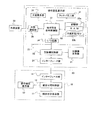
本実施の形態に係る計量包装システムの構成について、図13を参照して説明する。図13は、本実施の形態に係る計量包装システムの概略構成を示すブロック図である。 The configuration of the weighing packaging system according to the present embodiment will be described with reference to FIG. FIG. 13 is a block diagram showing a schematic configuration of the weighing packaging system according to the present embodiment.
本実施の形態に係る計量包装システムは、前記実施の形態1および2と同様に、組合せ秤10および包装機20を含み、組合せ秤10が、組合せ秤本体部11、組合せ秤制御部12、操作設定表示部13、およびインターフェース部14を備えており、包装機20が、包装機本体部21、包装機制御部22、操作設定表示部23、およびインターフェース部24を備えている。ただし、包装機20の操作設定表示部23に、通信監視器として機能する操作設定表示制御部37が設けられている。
The weighing and packaging system according to the present embodiment includes the
包装機20の操作設定表示部23の構成は、前述の組合せ秤10の操作設定表示部13の構成と同様であり、操作設定表示部37に加えて、タッチパネル部31、記憶部33(RAM33a、不揮発性メモリ33b)、I/O回路34、大型表示部35、および外部通信部36を備えている。また、外部通信部36は、外部装置30に接続されている。
The configuration of the operation setting
本実施の形態のように、包装機20側でインターフェース部24による通信の履歴を履歴データとして取得し、記憶部33に記憶させることによっても、前記実施の形態1または2と同様の作用効果を奏することができる。
As in the present embodiment, the history of communication by the
なお、本実施の形態では、前記動作制御データとして、包装情報が包装機制御部21から取得されるよう構成されている。具体的な包装情報は、包装機20の種類によって適宜設定されるものであり、特に限定されない。
In the present embodiment, packaging information is obtained from the packaging
また、本実施の形態では、組合せ秤10から送信され包装機20で受信する信号の受信時間は測定できるが、包装機20から送信され組合せ秤10で受信する信号の受信時間は測定できない。前記実施の形態1または2の場合に当てはめれば、排出準備完了信号や排出完了信号の受信時間は記憶できるが、排出要求信号や排出信号受取完了信号の受信時間は測定できない点で異なっている。
Moreover, in this Embodiment, although the reception time of the signal transmitted from the
つまり、前記実施の形態1または2では、組合せ秤10側での生じた不具合について原因の検証をしやすい構成となっていたが、本実施の形態では、包装機20側で生じた不具合について原因の検証がしやすくなる。したがって、計量包装システムの具体的な構成や発生が想定される不具合の種類等に応じて、実施の形態1から3のいずれの構成を採用するかを選択することができる。
In other words, in the first or second embodiment, the cause of the trouble that occurred on the
(実施の形態4)
前記実施の形態1から3では、計量包装システムは、外部装置30を除けば、組合せ秤10および包装機20で構成されていたが、本実施の形態では、計量包装システムがモニター機を含んでおり、このモニター機により、組合せ秤10および包装機20の間で送受信される連係用信号の履歴を記憶する。
(Embodiment 4)
In the first to third embodiments, the weighing and packaging system is composed of the
本実施の形態に係る計量包装システムの構成について、図14を参照して説明する。図14は、本実施の形態に係る計量包装システムおよび当該計量包装システムが含むモニター機の概略構成を示すブロック図である。 The configuration of the weighing and packaging system according to the present embodiment will be described with reference to FIG. FIG. 14 is a block diagram showing a schematic configuration of a weighing and packaging system according to the present embodiment and a monitor machine included in the weighing and packaging system.
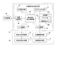
本実施の形態に係る計量包装システムは、前記実施の形態1から3と同様に、組合せ秤10および包装機20を含み、さらにモニター機40を含んでいる。また、組合せ秤10は、組合せ秤本体部11、組合せ秤制御部12、操作設定表示部13、およびインターフェース部14を備えており、包装機20は、包装機本体部21、包装機制御部22、操作設定表示部23、およびインターフェース部24を備えている。ただし、インターフェース部14,24は、モニター機との間で信号を送受信する。
The weighing and packaging system according to the present embodiment includes the
モニター機40は、組合せ秤10および包装機20の間に接続され、これら組合せ秤10および包装機20の少なくともいずれかの動作を監視する。その具体的構成は、前記実施の形態1および2における組合せ秤10の操作設定表示部13、または、前記実施の形態3における包装機20の操作設定表示部23の構成と同様であり、通信監視器としても機能するモニター制御部38と、タッチパネル部31、記憶部33(RAM33a、不揮発性メモリ33b)、I/O回路34、大型表示部35、および外部通信部36を備え、さらに、組合せ秤10との間で信号を送受信する第一インターフェース部41と、包装機20との間で信号を送受信する第二インターフェース部42とを備えている。また、外部通信部36は、外部装置30に接続されている。
The
本実施の形態に係る計量包装システムは、組合せ秤10および包装機20が、モニター機40を介して連係用信号を送受信するよう構成されている以外は、前記実施の形態1から3と同様である。モニター機40は、組合せ秤10および包装機20の間で送受信される連係用信号に関するデータ(タイミング設定時間t1〜t6のような信号の受信時間や信号の送受信の間隔等)を全て取得することができる点で優れている。ただし、モニター機40から組合せ秤10または包装機20に送信された信号に、何らかのノイズが伝播し、当該信号の波形が変形するなどの事態が発生したときには、モニター機40側では確認できない。この場合、組合せ秤10または包装機20に確認可能な構成を設ければよい。
The weighing and packaging system according to the present embodiment is the same as that of the first to third embodiments, except that the
なお、本実施の形態では、前記動作制御データとして、計量情報が組合せ秤制御部11から取得され、包装情報が包装機制御部21から取得されるよう構成されているが、いずれか一方のみを取得する構成であってもよい。
In the present embodiment, the operation control data is configured such that the weighing information is acquired from the combination
また、モニター機40は、外部装置30に内蔵される構成であってもよい。例えば、図14に示す構成では、モニター機40は、計量包装システムを構成する独立した処理装置として当該計量包装システムに含まれ、外部通信部36を介して外部装置30と通信するよう構成されている。これに対して、外部装置30は、インターフェース部により組合せ秤10および包装機20と通信するよう構成され、かつ、インターフェース部から取得した信号を処理するモニター部を備える構成であってもよい。このような外部装置30としては、例えば、計量包装システムの生産ラインに設置される重量選別機等の検査装置、あるいは、生産ライン全体を監視する生産ラインのモニター装置等を挙げることができる。
Further, the
前記構成では、外部装置30は、組合せ秤10および包装機20の双方と通信する構成であることが好ましいが、本発明はこれに限定されず、いずれか一方と通信する構成であればよい。前記実施の形態1ないし3で説明したように、本発明では、組合せ秤10または包装機20のいずれか一方の通信を監視して記録するのみでよいためである。
In the above-described configuration, the
なお、モニター機40は、それ単独で本発明の作用効果を奏することが可能である。すなわち、組合せ秤10および包装機20を含む独立した計量包装システムと通信可能に接続することで、本実施の形態に係る計量包装システムを構築することができる。
In addition, the
(実施の形態5)
前記実施の形態1から4では、計量包装システムは、組合せ秤10は操作設定表示部13を備え、包装機20は操作設定表示部23を備えていたが、本実施の形態では、組合せ秤10および包装機20が一つの計量包装装置を構成している。
(Embodiment 5)
In the first to fourth embodiments, in the weighing packaging system, the
本実施の形態に係る計量包装装置の構成について、図15を参照して説明する。図15は、本実施の形態に係る計量包装装置の概略構成を示すブロック図である。 The configuration of the weighing and packaging apparatus according to the present embodiment will be described with reference to FIG. FIG. 15 is a block diagram showing a schematic configuration of the weighing and packaging apparatus according to the present embodiment.
計量包装装置50は、組合せ秤本体部11、組合せ秤制御部12、包装機本体部21、包装機制御部22、共通操作設定表示部51を備えている。共通操作設定表示部51は、前記実施の形態1および2における組合せ秤10の操作設定表示部13、前記実施の形態3における包装機20の操作設定表示部23、または、前記実施の形態4におけるモニター機40の構成と同様であり、通信監視器としても機能する操作設定表示制御部39と、タッチパネル部31、記憶部33(RAM33a、不揮発性メモリ33b)、大型表示部35、および外部通信部36を備え、さらに、組合せ秤制御部12との間で情報を入出力するI/O回路52と、包装機制御部22との間で情報を入出力するI/O回路53とを備えている。また、外部通信部36は、外部装置30に接続されている。
The weighing and
本実施の形態に係る計量包装装置は、組合せ秤10および包装機20が一体化し、共通操作設定表示部51を備えている以外は、前記実施の形態1から4に開示する計量包装システムと同様である。ただし、本実施の形態では、異なる処理装置の間で連係用信号を通信するのではなく、一つのまとまった計量包装装置内で連係用信号を入出力するため、通信のロギングを行って通信の履歴データを取得するのではなく、連係用信号の入出力の履歴を履歴データとして取得する。また、本実施の形態でも、前記動作制御データとして、計量情報が組合せ秤制御部11から取得され、包装情報が包装機制御部21から取得されるよう構成されているが、いずれか一方のみを取得する構成であってもよい。
The weighing and packaging apparatus according to the present embodiment is the same as the weighing and packaging system disclosed in the first to fourth embodiments, except that the
前記構成であれば、組合せ秤制御部12および包装機制御部22の間で送受信される連係用信号に関するデータ(タイミング設定時間t1〜t6のような信号の受信時間や信号の送受信の間隔等)を全て取得することができる。ただし、組合せ秤本体部11および包装機本体部21は、計量包装装置50の一部となっているため、複数の処理装置からなるシステムとしての汎用性には欠ける。
If it is the said structure, the data regarding the signal for a link transmitted / received between the combination
このように、本発明は、少なくとも前記実施の形態1から5の異なる構成であっても実現可能である。したがって、各実施の形態で開示される構成の長所や短所を考慮して、適切な構成を選択することができる。 Thus, the present invention can be realized even with at least the different configurations of the first to fifth embodiments. Therefore, an appropriate configuration can be selected in consideration of the advantages and disadvantages of the configuration disclosed in each embodiment.
なお、本発明は上記の実施形態の記載に限定されるものではなく、特許請求の範囲に示した範囲内で種々の変更が可能であり、異なる実施形態や複数の変形例にそれぞれ開示された技術的手段を適宜組み合わせて得られる実施形態についても本発明の技術的範囲に含まれる。 It should be noted that the present invention is not limited to the description of the above-described embodiment, and various modifications are possible within the scope shown in the claims, and are disclosed in different embodiments and a plurality of modifications, respectively. Embodiments obtained by appropriately combining technical means are also included in the technical scope of the present invention.
本発明は、計量機と包装機とを組み合わせて用いる計量包装の分野に好適に用いることができる。 The present invention can be suitably used in the field of weighing packaging in which a weighing machine and a packaging machine are used in combination.
10 組合せ秤(計量機)
11 組合せ秤本体
12 組合せ秤制御部(動作制御器)
13 操作設定表示部(操作器)
14 インターフェース部(通信器)
20 包装機
21 包装機本体
22 包装機制御部(動作制御器)
23 操作設定表示部(操作器)
24 インターフェース部(通信器)
30 外部装置
31 タッチパネル部(操作器、出力器、表示器)
32 (組合せ秤の)操作設定表示制御部(操作制御器、通信監視器)
33 記憶部(記憶器)
35 大型表示部(出力器、表示器)
36 外部通信部(外部送信器)
37 (包装機の)操作設定表示制御部(操作制御器、通信監視器)
38 モニター制御部(モニター制御器)
39 (共通操作設定表示部の)操作設定表示制御部(操作制御器)
40 モニター機(計量包装システム用モニター装置)
41 第一インターフェース部(計量機用通信器)
42 第二インターフェース部(包装機用通信器)
50 計量包装装置
51 共通操作設定表示部(共通操作機)
10 Combination weigher (weighing machine)
11
13 Operation setting display (operator)
14 Interface unit (communication device)
20
23 Operation setting display (operator)
24 Interface unit (communication device)
30
32 Operation setting display control unit (operation controller, communication monitor)
33 Memory unit (memory device)
35 Large display (output, display)
36 External communication unit (external transmitter)
37 Operation setting display control unit (operation controller, communication monitoring device)
38 Monitor controller (monitor controller)
39 Operation setting display control unit (operation controller) (of common operation setting display unit)
40 Monitor machine (monitoring device for measuring and packaging system)
41 First interface unit (communication device for weighing machine)
42 Second interface unit (communication device for packaging machine)
50 Weighing
Claims (5)
前記計量機および前記包装機の少なくともいずれか一方の処理装置は、記憶器と、操作器と、出力器と、前記通信器による通信の履歴を履歴データとして取得し、前記記憶器に記憶させる通信監視器と、をさらに備え、
前記通信監視器は、前記履歴データとして、前記通信器から、前記連係用信号を送受信した年月日および時刻と、前記連係用信号の送受信が行われた時間である通信時間と、前記連係用信号の送受信の間隔である通信間隔と、を取得するとともに、前記動作制御器から、計量または包装した前記物品の種類と、を取得し、
前記操作器の操作に応じて、前記記憶器に記憶されている前記履歴データを前記出力器に出力させ、
さらに、前記記憶器には、前記通信時間および前記通信間隔に対して予め設定される許容範囲が記憶され、前記計量排出動作および前記包装動作が停止しているときには、前記記憶器に記憶されている前記履歴データのうち、前記通信時間および前記通信間隔が前記許容範囲内であるか否かを判定し、前記許容範囲内であれば前記記憶器から削除し、前記履歴データが削除された前記記憶器の領域に、次の履歴データをシフトさせることにより、前記記憶器の履歴データ領域を圧縮するように構成されている、計量包装システム。 A weighing machine that weighs and discharges the article so that it falls within a preset allowable range of the packaging weight; and a packaging machine that packages the discharged article with a packaging material, the weighing machine and the packaging Each of the machines comprises an operation controller for controlling the weighing discharge operation of the weighing machine or the packaging operation of the packaging machine, and a communication device for transmitting and receiving a linking signal for linking the weighing discharge operation and the packaging operation.
The processing device of at least one of the weighing machine and the packaging machine acquires a communication history by a storage device, an operation device, an output device, and the communication device as history data, and stores the communication history in the storage device. A monitoring device, and
The communication monitor includes, as the history data, a date and time when the link signal is transmitted / received from the communication device, a communication time which is a time when the link signal is transmitted / received, and the link data Obtaining a communication interval that is an interval of signal transmission and reception, and obtaining the type of the article weighed or packaged from the operation controller,
In response to the operation of the operation device, the history data stored in the storage device is output to the output device,
Further, the storage device stores an allowable range set in advance with respect to the communication time and the communication interval, and is stored in the storage device when the weighing and discharging operation and the packaging operation are stopped. Determining whether or not the communication time and the communication interval are within the allowable range, and deleting the history data from the storage device and deleting the history data. A weighing and packaging system configured to compress the history data area of the memory by shifting the next history data to the area of the memory.
前記計量機および前記包装機は、それぞれ、前記計量機の計量排出動作または前記包装機の包装動作を制御する動作制御器と、前記モニター機との間で信号を送受信する通信器とを備え、
前記モニター機は、記憶器と、操作器と、出力器と、前記計量機との間で信号を送受信する計量機用通信器と、前記包装機との間で信号を送受信する包装機用通信器と、当該モニター機の動作を制御するモニター制御器と、をさらに備え、
前記計量機および前記包装機は、前記モニター機を介して、前記計量排出動作および前記包装動作を連係させる連係用信号を送受信するよう構成され、
前記モニター制御器は、前記計量機用通信器または前記包装機用通信器による通信の履歴データとして、前記計量機用通信器または前記包装機用通信器から、前記連係用信号を送受信した年月日および時刻と、前記連係用信号の送受信が行われた時間である通信時間と、前記連係用信号の送受信の間隔である通信間隔と、を取得するとともに、前記計量機または前記包装機の前記動作制御器から、計量または包装した前記物品の種類と、を取得し、前記記憶器に記憶させるとともに、
前記操作器の操作に応じて、前記記憶器に記憶されている前記履歴データを前記出力器に出力させ、
さらに、前記記憶器には、前記通信時間および前記通信間隔に対して予め設定される許容範囲が記憶され、前記計量排出動作および前記包装動作が停止しているときには、前記記憶器に記憶されている前記履歴データのうち、前記通信時間および前記通信間隔が前記許容範囲内であるか否かを判定し、前記許容範囲内であれば前記記憶器から削除し、前記履歴データが削除された前記記憶器の領域に、次の履歴データをシフトさせることにより、前記記憶器の履歴データ領域を圧縮するよう構成されている、計量包装システム。 Between a weighing machine that weighs and discharges articles so as to be within a preset allowable range of packaging weight, a packaging machine that packages the discharged articles with packaging materials, and between the weighing machine and the packaging machine And a monitoring machine that monitors the operation of at least one of the weighing machine and the packaging machine,
Each of the weighing machine and the packaging machine includes an operation controller that controls a weighing discharge operation of the weighing machine or a packaging operation of the packaging machine, and a communication device that transmits and receives signals to and from the monitoring machine.
The monitor machine includes a storage device, an operating device, an output device, a weighing machine communication device that transmits and receives signals to and from the weighing machine, and a packaging machine communication that transmits and receives signals to and from the packaging machine. And a monitor controller for controlling the operation of the monitor machine,
The weighing machine and the packaging machine are configured to transmit and receive a signal for linking that links the weighing discharge operation and the packaging operation via the monitoring machine,
The monitor controller transmits and receives the linkage signal from the weighing machine communication device or the packaging machine communication device as history data of communication by the weighing machine communication device or the packaging machine communication device. Obtaining a date and time, a communication time that is a time when transmission / reception of the linkage signal is performed, and a communication interval that is an interval of transmission / reception of the linkage signal, and the weighing machine or the packaging machine From the operation controller, the type of the item weighed or packaged is acquired and stored in the storage unit,
In response to the operation of the operation device, the history data stored in the storage device is output to the output device,
Further, the storage device stores an allowable range set in advance with respect to the communication time and the communication interval, and is stored in the storage device when the weighing and discharging operation and the packaging operation are stopped. Determining whether or not the communication time and the communication interval are within the allowable range, and deleting the history data from the storage device and deleting the history data. A weighing and packaging system configured to compress the history data area of the memory by shifting the next history data to the area of the memory.
記憶器と、操作器と、出力器と、前記計量機の前記通信器と接続することで前記計量機との間で信号を送受信する計量機用通信器と、前記包装機の前記通信器と接続することで前記包装機との間で信号を送受信する包装機用通信器と、制御器と、を備え、
前記制御器は、前記計量機用通信器または前記包装機用通信器による通信の履歴データとして、前記計量機用通信器または前記包装機用通信器から、前記連係用信号を送受信した年月日および時刻と、前記連係用信号の送受信が行われた時間である通信時間と、前記連係用信号の送受信の間隔である通信間隔と、を取得するとともに、前記計量機または前記包装機が備える動作制御器から、計量または包装した前記物品の種類と、を取得し、前記記憶器に記憶させるとともに、
前記操作器の操作に応じて、前記記憶器に記憶されている前記履歴データを前記出力器に出力させ、
さらに、前記記憶器には、前記通信時間および前記通信間隔に対して予め設定される許容範囲が記憶され、前記計量排出動作および前記包装動作が停止しているときに、前記記憶器に記憶されている前記履歴データのうち、前記通信時間および前記通信間隔が前記許容範囲内であるか否かを判定し、前記許容範囲内であれば前記記憶器から削除し、前記履歴データが削除された前記記憶器の領域に、次の履歴データをシフトさせることにより、前記記憶器の履歴データ領域を圧縮するよう構成されている、計量包装システム用モニター装置。 A weighing machine that weighs and discharges the article so that it falls within a preset allowable range of the packaging weight; and a packaging machine that packages the discharged article with a packaging material, the weighing machine and the packaging The machine is used in a weighing and packaging system including a communication device that transmits and receives a signal for linkage that links the weighing and discharging operation of the weighing machine and the packaging operation of the packaging machine,
A storage device, an operating device, an output device, a communication device for a weighing machine that transmits and receives signals to and from the weighing machine by connecting to the communication device of the weighing machine, and the communication device of the packaging machine A packaging machine communicator for transmitting and receiving signals to and from the packaging machine by connecting, and a controller;
The controller is configured to transmit / receive the linkage signal from the weighing machine communication device or the packaging machine communication device as history data of communication by the weighing machine communication device or the packaging machine communication device. And the time, the communication time that is the time when transmission / reception of the linkage signal is performed, and the communication interval that is the interval of transmission / reception of the linkage signal, and the operation provided in the weighing machine or the packaging machine From the controller, the type of the item weighed or packaged is acquired and stored in the storage unit,
In response to the operation of the operation device, the history data stored in the storage device is output to the output device,
Further, the storage device stores a preset allowable range for the communication time and the communication interval, and is stored in the storage device when the weighing and discharging operation and the packaging operation are stopped. Among the history data, it is determined whether the communication time and the communication interval are within the allowable range. If the communication time and the communication interval are within the allowable range, the history data is deleted from the storage device. A monitoring device for a weighing and packaging system configured to compress the history data area of the memory by shifting the next history data to the area of the memory.
前記共通操作機は、記憶器と、操作器と、出力器と、前記操作器の操作に応じて前記計量機、前記包装機、前記記憶器、前記出力器への情報の入出力を制御する操作制御器と、を備え、
前記計量機および前記包装機は、前記共通操作機を介して、前記計量機の計量排出動作および前記包装機の包装動作を連係させる連係用信号を送受信するよう構成され、
前記共通操作機の前記操作制御器は、前記計量機または前記包装機からの連係用信号の入出力の履歴と、計量または包装した前記物品の種類とを信号入出力の履歴データとして取得し、前記記憶器に記憶させるとともに、前記操作器の操作に応じて、前記記憶器に記憶されている前記履歴データを前記出力器に出力させ、
さらに、前記記憶器には、前記連係用信号の送受信が行われた時間である通信時間および前記連係用信号の送受信の間隔である通信間隔に対して予め設定される許容範囲が記憶され、前記計量排出動作および前記包装動作が停止しているときには、前記記憶器に記憶されている前記履歴データのうち、前記通信時間および前記通信間隔が前記許容範囲内であるか否かを判定し、前記許容範囲内であれば前記記憶器から削除し、前記履歴データが削除された前記記憶器の領域に、次の履歴データをシフトさせることにより、前記記憶器の履歴データ領域を圧縮するよう構成され、
前記操作制御器により取得される前記履歴データは、
前記連係用信号を送受信した年月日および時刻、前記通信時間、および、前記通信間隔である、計量包装装置。 Operate the weighing machine that weighs and discharges articles so as to be within a pre-set tolerance of the packaging weight, the packaging machine that wraps the discharged articles with packaging materials, and the weighing machine and the packaging machine A common operating device,
The common operating device controls input / output of information to the weighing machine, the packaging machine, the storage device, and the output device according to the operation of the storage device, the operating device, the output device, and the operating device. An operation controller,
The weighing machine and the packaging machine are configured to transmit and receive a linking signal that links the weighing discharge operation of the weighing machine and the packaging operation of the packaging machine via the common operating device,
The operation controller of the common operating device acquires the input / output history of the linkage signal from the weighing machine or the packaging machine and the type of the article weighed or packaged as signal input / output history data, While storing in the storage device, according to the operation of the operation device, the history data stored in the storage device is output to the output device,
Further, the storage unit stores a communication time that is a time when the transmission / reception of the linkage signal is performed and an allowable range that is set in advance for a communication interval that is an interval of the transmission / reception of the linkage signal , When the weighing and discharging operation and the packaging operation are stopped, it is determined whether or not the communication time and the communication interval are within the allowable range among the history data stored in the storage device, If it is within the allowable range, the history data area of the storage device is compressed by deleting from the storage device and shifting the next history data to the storage device area from which the history data has been deleted. ,
The history data acquired by the operation controller is
The weighing and packaging apparatus, which is the date and time when the link signal is transmitted and received, the communication time , and the communication interval .
Priority Applications (1)
| Application Number | Priority Date | Filing Date | Title |
|---|---|---|---|
| JP2008267306A JP5259331B2 (en) | 2008-10-16 | 2008-10-16 | Weighing and packaging system, monitor device used therefor, and weighing and packaging device |
Applications Claiming Priority (1)
| Application Number | Priority Date | Filing Date | Title |
|---|---|---|---|
| JP2008267306A JP5259331B2 (en) | 2008-10-16 | 2008-10-16 | Weighing and packaging system, monitor device used therefor, and weighing and packaging device |
Publications (2)
| Publication Number | Publication Date |
|---|---|
| JP2010096619A JP2010096619A (en) | 2010-04-30 |
| JP5259331B2 true JP5259331B2 (en) | 2013-08-07 |
Family
ID=42258409
Family Applications (1)
| Application Number | Title | Priority Date | Filing Date |
|---|---|---|---|
| JP2008267306A Expired - Fee Related JP5259331B2 (en) | 2008-10-16 | 2008-10-16 | Weighing and packaging system, monitor device used therefor, and weighing and packaging device |
Country Status (1)
| Country | Link |
|---|---|
| JP (1) | JP5259331B2 (en) |
Families Citing this family (2)
| Publication number | Priority date | Publication date | Assignee | Title |
|---|---|---|---|---|
| JP6487260B2 (en) * | 2015-04-10 | 2019-03-20 | 株式会社イシダ | Combination weighing device |
| JP7493485B2 (en) * | 2021-07-21 | 2024-05-31 | アンリツ株式会社 | Production management system and production management program |
Family Cites Families (4)
| Publication number | Priority date | Publication date | Assignee | Title |
|---|---|---|---|---|
| JPH0472121A (en) * | 1990-07-06 | 1992-03-06 | Yamato Scale Co Ltd | Interlock monitor |
| JP2000289717A (en) * | 1999-04-07 | 2000-10-17 | Ishida Co Ltd | Weighing and packaging inspection system |
| JP4302821B2 (en) * | 1999-06-22 | 2009-07-29 | 株式会社イシダ | Weighing and bag making and packaging system |
| JP4710400B2 (en) * | 2005-04-26 | 2011-06-29 | 株式会社寺岡精工 | Work instruction weighing device |
-
2008
- 2008-10-16 JP JP2008267306A patent/JP5259331B2/en not_active Expired - Fee Related
Also Published As
| Publication number | Publication date |
|---|---|
| JP2010096619A (en) | 2010-04-30 |
Similar Documents
| Publication | Publication Date | Title |
|---|---|---|
| EP0614814B1 (en) | System for integrating machines | |
| US6401437B1 (en) | Weighing and packaging system | |
| JP3734883B2 (en) | Production line management method and management apparatus | |
| EP3281156A1 (en) | Systems and methods for monitoring food processing and food storage | |
| JPWO1994008850A1 (en) | Device Integration System | |
| CN104980312A (en) | A Portable Testing Apparatus And Method | |
| CN113650887B (en) | Automatic packing method and system for home textile products | |
| JP5259331B2 (en) | Weighing and packaging system, monitor device used therefor, and weighing and packaging device | |
| AU2005285947B2 (en) | Combination weigher | |
| JP5824246B2 (en) | Production line management device | |
| JP2002350194A (en) | Transport environment data recording device, transport environment data collection method, and transport environment data analysis method | |
| JP2012226642A (en) | Maintenance inspection system | |
| EP4030248A1 (en) | Management device and article management system | |
| KR20000059044A (en) | Remote Control Method and System of Rice Processing Complex | |
| CN116767619B (en) | Production management equipment, production management system, combined metering equipment and packaging equipment | |
| JP4977496B2 (en) | Weighing device, weighing system, and output method of setting items relating to these | |
| JP2010038604A (en) | Combination weighing apparatus | |
| JP2011191074A (en) | Metering system and packaging system | |
| CN216003294U (en) | Automatic boxing system for home textile products | |
| CN110271878B (en) | PLC control system | |
| JP4145399B2 (en) | Combination weighing device | |
| JP2010043999A (en) | Combination counting device and combination counting method | |
| CN115390515B (en) | Production management system and storage medium storing production management program | |
| JP7438164B2 (en) | Production management system and production management program | |
| JP7438165B2 (en) | Production management system and production management program |
Legal Events
| Date | Code | Title | Description |
|---|---|---|---|
| A621 | Written request for application examination |
Free format text: JAPANESE INTERMEDIATE CODE: A621 Effective date: 20110907 |
|
| A977 | Report on retrieval |
Free format text: JAPANESE INTERMEDIATE CODE: A971007 Effective date: 20121114 |
|
| A131 | Notification of reasons for refusal |
Free format text: JAPANESE INTERMEDIATE CODE: A131 Effective date: 20121127 |
|
| A521 | Written amendment |
Free format text: JAPANESE INTERMEDIATE CODE: A523 Effective date: 20130118 |
|
| A131 | Notification of reasons for refusal |
Free format text: JAPANESE INTERMEDIATE CODE: A131 Effective date: 20130226 |
|
| A521 | Written amendment |
Free format text: JAPANESE INTERMEDIATE CODE: A523 Effective date: 20130327 |
|
| TRDD | Decision of grant or rejection written | ||
| A01 | Written decision to grant a patent or to grant a registration (utility model) |
Free format text: JAPANESE INTERMEDIATE CODE: A01 Effective date: 20130416 |
|
| A61 | First payment of annual fees (during grant procedure) |
Free format text: JAPANESE INTERMEDIATE CODE: A61 Effective date: 20130424 |
|
| FPAY | Renewal fee payment (event date is renewal date of database) |
Free format text: PAYMENT UNTIL: 20160502 Year of fee payment: 3 |
|
| R150 | Certificate of patent or registration of utility model |
Ref document number: 5259331 Country of ref document: JP Free format text: JAPANESE INTERMEDIATE CODE: R150 Free format text: JAPANESE INTERMEDIATE CODE: R150 |
|
| R250 | Receipt of annual fees |
Free format text: JAPANESE INTERMEDIATE CODE: R250 |
|
| R250 | Receipt of annual fees |
Free format text: JAPANESE INTERMEDIATE CODE: R250 |
|
| R250 | Receipt of annual fees |
Free format text: JAPANESE INTERMEDIATE CODE: R250 |
|
| LAPS | Cancellation because of no payment of annual fees |