JP5259241B2 - Motor controller, motor drive system, washing machine, air conditioner, method of changing the amount of magnetization of a permanent magnet motor - Google Patents
Motor controller, motor drive system, washing machine, air conditioner, method of changing the amount of magnetization of a permanent magnet motor Download PDFInfo
- Publication number
- JP5259241B2 JP5259241B2 JP2008112437A JP2008112437A JP5259241B2 JP 5259241 B2 JP5259241 B2 JP 5259241B2 JP 2008112437 A JP2008112437 A JP 2008112437A JP 2008112437 A JP2008112437 A JP 2008112437A JP 5259241 B2 JP5259241 B2 JP 5259241B2
- Authority
- JP
- Japan
- Prior art keywords
- motor
- permanent magnet
- induced voltage
- magnetization
- amount
- Prior art date
- Legal status (The legal status is an assumption and is not a legal conclusion. Google has not performed a legal analysis and makes no representation as to the accuracy of the status listed.)
- Expired - Fee Related
Links
Images


Classifications
-
- H—ELECTRICITY
- H02—GENERATION; CONVERSION OR DISTRIBUTION OF ELECTRIC POWER
- H02P—CONTROL OR REGULATION OF ELECTRIC MOTORS, ELECTRIC GENERATORS OR DYNAMO-ELECTRIC CONVERTERS; CONTROLLING TRANSFORMERS, REACTORS OR CHOKE COILS
- H02P21/00—Arrangements or methods for the control of electric machines by vector control, e.g. by control of field orientation
- H02P21/14—Estimation or adaptation of machine parameters, e.g. flux, current or voltage
Landscapes
- Engineering & Computer Science (AREA)
- Power Engineering (AREA)
- Control Of Ac Motors In General (AREA)
- Control Of Motors That Do Not Use Commutators (AREA)
- Control Of Washing Machine And Dryer (AREA)
- Control Of Direct Current Motors (AREA)
- Permanent Field Magnets Of Synchronous Machinery (AREA)
Description
本発明は、着磁量を変更可能な程度に低保磁力である永久磁石が回転子に配置される永久磁石モータを駆動するモータ制御装置,及び前記永久磁石モータとモータ制御装置とで構成されるモータ駆動システム,並びにそのシステムを備えてなる洗濯機,空調機,更に前記永久磁石モータの着磁量変更方法に関する。 The present invention includes a motor control device that drives a permanent magnet motor in which a permanent magnet having a coercive force that is low enough to change the amount of magnetization is arranged on a rotor, and the permanent magnet motor and the motor control device. The present invention relates to a motor drive system, a washing machine, an air conditioner, and a method for changing the amount of magnetization of the permanent magnet motor.
近年、消費電力の低減を目的として、永久磁石モータをインバータ装置によりベクトル制御して、低速から高速まで可変速運転する技術が普及している。また、特許文献1には、可変速運転範囲の全体に亘ってモータ効率を向上させることができ、信頼性の向上を実現する永久磁石式モータとして、以下のような構成が開示されている。当該モータは、巻線を設けた固定子と、固定子巻線の電流で作る磁界により不可逆的に磁束密度が変化する程度の低保磁力の永久磁石と、前記低保磁力の2倍以上の保磁力を有する高保磁力の永久磁石を配置した回転子から構成されている。そして、電源電圧の最大電圧以上となる高速回転運転を行う場合は、低保磁力の永久磁石と高保磁力の永久磁石による全鎖交磁束が減じるように、電流による磁界で低保磁力の永久磁石を磁化させて全鎖交磁束量を調整することを可能としている。
特許文献1では、低保磁力永久磁石を磁化させる場合、ベクトル制御で得られるd軸電流をモータの固定子巻線に通電しているが、その電流値や通電回数は、実験により求めたデータに基づいて行うことになる。例えば、d軸電流を負方向に10A通電すると、モータの磁束量が10%減少する、という実験結果に基づき電流値や通電回数を決定する。しかしながら、この場合、低保磁力永久磁石を増減磁させた結果、モータの回転子磁束量が実際にどの程度の量になっているかは不明であるため、必ずしも最適な効率でモータを運転することができるとは限らないという問題があった。
In
本発明は上記事情に鑑みてなされたものであり、その目的は、実際に着磁状態を変化させたモータの回転子磁束量を定量的に評価できるモータ制御装置,及び永久磁石モータとモータ制御装置とで構成されるモータ駆動システム,並びにそのシステムを備えてなる洗濯機,空調機,更に前記永久磁石モータの着磁量変更方法を提供することにある。 The present invention has been made in view of the above circumstances, and an object of the present invention is to provide a motor control device capable of quantitatively evaluating the amount of rotor magnetic flux of a motor that has actually changed the magnetization state, and a permanent magnet motor and motor control. Another object of the present invention is to provide a motor drive system including the apparatus, a washing machine including the system, an air conditioner, and a method for changing the amount of magnetization of the permanent magnet motor.
上記目的を達成するため、請求項1記載のモータ制御装置は、着磁量を変更可能な程度に低保磁力である永久磁石が回転子に配置される永久磁石モータを制御するものにおいて、
前記モータの巻線に通電を行うことで駆動する駆動手段と、
この駆動手段を介して前記モータの巻線に通電を行い、前記永久磁石の着磁量を変化させる着磁制御手段と、
前記モータに通電される電流を検出する電流検出手段と、
前記モータ電流と、前記駆動手段の出力電圧と、前記モータの定数とに基づいて、前記モータの回転速度ω及び回転位置を演算して推定する速度・位置推定手段を備え、前記駆動手段を介して前記モータをベクトル制御するベクトル制御手段と、
前記モータの回転速度ωと、前記ベクトル制御手段により求められるモータ電流Id,Iqと、前記駆動手段の出力電圧Vd,Vqと、前記モータの定数である巻線インダクタンスLd,Lq及び巻線抵抗Rとから、前記モータの誘起電圧を検出する誘起電圧検出手段と、
前記モータの回転速度ωと前記モータの出力トルクTとに基づいて、誘起電圧指令を決定する誘起電圧指令決定手段と、
前記モータの誘起電圧と、前記誘起電圧指令とに基づいて、前記着磁制御手段による通電量を決定する着磁電流決定手段とを備えたことを特徴とする。
In order to achieve the above object, the motor control device according to claim 1 controls a permanent magnet motor in which a permanent magnet having a low coercive force so that the amount of magnetization can be changed is arranged on a rotor.
Driving means for driving by energizing the windings of the motor;
Magnetization control means for energizing the windings of the motor through the driving means and changing the magnetization amount of the permanent magnets;
Current detecting means for detecting a current supplied to the motor;
Speed / position estimation means for calculating and estimating the rotational speed ω and rotational position of the motor based on the motor current, the output voltage of the driving means, and the constant of the motor, and through the driving means Vector control means for vector controlling the motor;
The rotational speed ω of the motor, motor currents Id and Iq determined by the vector control means, output voltages Vd and Vq of the driving means, winding inductances Ld and Lq and winding resistance R as constants of the motor. And induced voltage detection means for detecting the induced voltage of the motor;
Induced voltage command determining means for determining an induced voltage command based on the rotational speed ω of the motor and the output torque T of the motor;
Magnetizing current determining means for determining an energization amount by the magnetizing control means based on the induced voltage of the motor and the induced voltage command is provided.
また、請求項5記載のモータ駆動システムは、着磁量を変更可能な程度に低保磁力である永久磁石が回転子に配置される永久磁石モータと、請求項1乃至4の何れか記載のモータ制御装置とで構成されることを特徴とする。
The motor drive system according to
また、請求項6記載の洗濯機は、請求項5記載のモータ駆動システムを備え、前記永久磁石モータによって、洗濯運転や脱水運転を行うための駆動力を発生させるように構成されていることを特徴とする。
また、請求項8記載の空調機は、請求項5記載のモータ駆動システムを備え、前記永久磁石モータによって、コンプレッサを駆動することを特徴とする。
According to a sixth aspect of the present invention, there is provided a washing machine comprising the motor driving system according to the fifth aspect, wherein the permanent magnet motor is configured to generate a driving force for performing a washing operation or a dehydrating operation. Features.
An air conditioner according to an eighth aspect includes the motor drive system according to the fifth aspect, wherein the compressor is driven by the permanent magnet motor.
請求項9記載の永久磁石モータの着磁量変更方法は、着磁量を変更可能な程度に低保磁力である永久磁石が回転子に配置される永久磁石モータについて、駆動手段を介して前記モータに通電される電流を検出し、
前記モータ電流と、前記駆動手段の出力電圧と、前記モータの定数とに基づいて、前記モータの回転速度ω及び回転位置を演算して推定してベクトル制御する場合に、前記駆動手段を介して前記永久磁石の着磁量を変更する方法において、
前記モータの回転速度ωと、前記ベクトル制御で求められるモータ電流Id,Iqと、前記駆動手段の出力電圧Vd,Vqと、前記モータの定数である巻線インダクタンスLd,Lq及び巻線抵抗Rとから、前記モータの誘起電圧を検出し、
前記モータの回転速度ωと、前記モータの出力トルクTとに基づいて、誘起電圧指令を決定すると、
前記モータの誘起電圧と、前記誘起電圧指令とに基づいて、前記着磁制御手段による通電量を決定することを特徴とする。
The method for changing the amount of magnetization of a permanent magnet motor according to
Based on the motor current, the output voltage of the driving means, and the constants of the motor, the rotational speed ω and the rotational position of the motor are calculated and estimated and vector control is performed. In the method of changing the magnetization amount of the permanent magnet,
The rotational speed ω of the motor, motor currents Id and Iq determined by the vector control, output voltages Vd and Vq of the driving means, winding inductances Ld and Lq and winding resistance R which are constants of the motor, From this, the induced voltage of the motor is detected,
When the induced voltage command is determined based on the rotational speed ω of the motor and the output torque T of the motor,
The energization amount by the magnetization control means is determined based on the induced voltage of the motor and the induced voltage command.
請求項1記載のモータ制御装置によれば、永久磁石モータの回転子を構成する永久磁石の着磁量を、要求される駆動特性に応じて適切に変化させることができるので、モータの運転効率を向上させることができる。
請求項5記載のモータ駆動システムによれば、本発明モータ制御装置により永久磁石の着磁量を適切に変化させて永久磁石モータを駆動制御することで、モータの運転効率を向上可能なシステムを提供できる。
According to the motor control device of the first aspect, the amount of magnetization of the permanent magnet constituting the rotor of the permanent magnet motor can be appropriately changed according to the required drive characteristics. Can be improved.
According to the motor drive system of the fifth aspect of the present invention, there is provided a system capable of improving the operation efficiency of the motor by controlling the drive of the permanent magnet motor by appropriately changing the magnetization amount of the permanent magnet by the motor control device of the present invention. Can be provided.
請求項6記載の洗濯機,また請求項8記載の空調機によれば、永久磁石モータの特性を各運転に適するように変化させ、モータの運転効率を向上させ、低消費電力化を図ることができる。
請求項9記載の永久磁石モータの着磁量変更方法によれば、請求項1と同様に、永久磁石モータの回転子を構成する永久磁石の着磁量を、要求される駆動特性に応じて適切に変化させて、モータの運転効率を向上させることができる。
According to the washing machine as set forth in
According to the method for changing the magnetizing amount of the permanent magnet motor according to
(第1実施例)
以下、本発明の第1実施例について図1乃至図8を参照しながら説明する。図5は、永久磁石モータ1(アウタロータ型ブラシレスモータ)の回転子の構成を示す斜視図である。尚、この永久磁石モータ1は、特許文献1に開示されているものと同様の特徴を有するモータを、アウタロータ型として構成したものである。
(First embodiment)
A first embodiment of the present invention will be described below with reference to FIGS. FIG. 5 is a perspective view showing the configuration of the rotor of the permanent magnet motor 1 (outer rotor type brushless motor). In addition, this
永久磁石モータ1は、固定子2と、これの外周に設けた回転子3とから構成されている。固定子2は、固定子コア4と固定子巻線5とから構成されている。固定子コア4は、打ち抜き形成した軟磁性体であるケイ素鋼板を多数枚積層し且つかしめることにより構成したもので、環状のヨーク部4aと、当該ヨーク部4aの外周部から放射状に突出する多数のティース部4bとを有している。固定子コア4の表面は、回転子3の内周面との間に空隙を形成する外周面4c(各ティース部4bの先端面)を除き、PET樹脂(モールド樹脂)により覆われている。
The
また、このPET樹脂から成る複数の取付部6が、固定子2の内周部に一体的に成形されている。これら取付部6には複数のねじ穴6aが設けられており、これら取付部6をねじ止めすることで、固定子2が、この場合、ドラム式洗濯乾燥機21の水槽25(図7参照)の背面に固着されるようになっている。固定子巻線5は三相からなり、各ティース部4bに巻装されている。
A plurality of
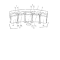
回転子3は、フレーム7と回転子コア8と複数の永久磁石9とを図示しないモールド樹脂により一体化した構成となっている。フレーム7は、磁性体である例えば鉄板をプレス加工することにより扁平な有底円筒状に形成したもので、円形の主板部7aと、この主板部7aの外周部から段部7bを経て起立する環状の周側壁7cとを有する。主板部7aの中心部には、回転軸26(図7参照)を取付けるための軸取付部10が設けられており、この軸取付部10と段部7bとの間には、複数の通風孔11およびリブ12が軸取付部10を中心に放射状に形成されている。
The
回転子コア8は、ほぼ環状に打ち抜き形成した軟磁性体であるケイ素鋼板を多数枚積層し且つかしめることにより構成したもので、フレーム7の周側壁7cの内周部に配置されている。この回転子コア8の内周面(固定子2の外周面(固定子コア4の外周面4c)と対向し当該固定子2との間に空隙を形成する面)は、内方に向けて円弧状に突出する複数の凸部8aを有した凹凸状に形成されている。
The
図6にも示すように、これら複数の凸部8aの内部には、回転子コア8を軸方向(ケイ素鋼板の積層方向)に貫通する矩形状の挿入穴13が形成されており、これら複数の挿入穴13が回転子コア8において環状に配置された構成となっている。また、これら複数の挿入穴13は、短辺の長さが異なる2種類の挿入穴13a,13bから構成されており、これら挿入穴13a,13bは、回転子コア8の周方向に沿って1つずつ交互に配置されている。
As shown in FIG. 6, a
永久磁石9は、挿入穴13aに挿入された矩形状のネオジム磁石9a(高保磁力永久磁石)と、挿入穴13bに挿入された矩形状のアルニコ磁石9b(低保磁力永久磁石)とから構成されている。この場合、ネオジム磁石9aの保磁力は約900kA/m、アルニコ磁石9bの保磁力は約100kA/mであり、保磁力が9倍程度異なっている。すなわち、永久磁石9は保磁力が異なる2種類の永久磁石9a,9bから構成され、これら永久磁石9a,9bは、回転子コア8内部においてほぼ環状に且つ1つずつ交互に配置されている。
The
また、これら2種類の永久磁石9a,9bは、それぞれ1種類で1磁極を形成しており、その磁化方向が永久磁石モータ1の径方向(永久磁石モータ1の外周部から固定子2と回転子3間の空隙に向かう方向)に沿うように配設されている。このように2種類の永久磁石9a,9bを、交互に且つその磁化方向が径方向に沿うように配置することにより、隣同士に配置された永久磁石9a,9bが互いに反対方向に磁極を有する状態(一方のN極が内側、他方のN極が外側となる状態)となり、これらネオジム磁石9aとアルニコ磁石9bとの間に例えば矢印Bで示す方向に磁気経路(磁束)が生ずる。尚、上方の破線で示す矢印は、回転子コア8を経由する磁束である。すなわち、保磁力が大きいネオジム磁石9aと保磁力が小さいアルニコ磁石9bの双方を通過する磁気経路が形成されるようになっている。
Each of these two types of
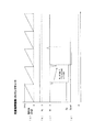
次に、上記のように構成された永久磁石モータ1を備えたドラム式洗濯乾燥機21の構成について説明する。図7は、ドラム式洗濯乾燥機21の内部構成を概略的に示す縦断側面図である。ドラム式洗濯乾燥機21の外殻を形成する外箱22は、前面に円形状に開口する洗濯物出入口23を有しており、この洗濯物出入口23は、ドア24により開閉されるようになっている。外箱22の内部には、背面が閉鎖された有底円筒状の水槽25が配置されており、この水槽25の背面中央部には上述の永久磁石モータ1(固定子2)がねじ止めにより固着されている。この永久磁石モータ1の回転軸26は、後端部(図7では右側の端部)が永久磁石モータ1(回転子3)の軸取付部10に固定されており、前端部(図7では左側の端部)が水槽25内に突出している。回転軸26の前端部には、背面が閉鎖された有底円筒状のドラム27が水槽25に対して同軸状となるように固定されており、このドラム27は、永久磁石モータ1の駆動により回転子3および回転軸26と一体的に回転する。なお、ドラム27には、空気および水を流通可能な複数の流通孔28と、ドラム27内の洗濯物の掻き上げやほぐしを行うための複数のバッフル29が設けられている。
Next, the structure of the drum type washing / drying machine 21 provided with the
水槽25には給水弁30が接続されており、当該給水弁30が開放されると、水槽25内に給水されるようになっている。また、水槽25には排水弁31を有する排水ホース32が接続されており、当該排水弁31が開放されると、水槽25内の水が排出されるようになっている。
水槽25の下方には、前後方向へ延びる通風ダクト33が設けられている。この通風ダクト33の前端部は前部ダクト34を介して水槽25内に接続されており、後端部は後部ダクト35を介して水槽25内に接続されている。通風ダクト33の後端部には、送風ファン36が設けられており、この送風ファン36の送風作用により、水槽25内の空気が、矢印で示すように、前部ダクト34から通風ダクト33内に送られ、後部ダクト35を通して水槽25内に戻されるようになっている。
A
A
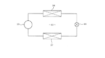
通風ダクト33内部の前端側には蒸発器37が配置されており、後端側には凝縮器38が配置されている。これら蒸発器37および凝縮器38は、コンプレッサ39および絞り弁40とともにヒートポンプ41を構成しており(図8参照)、通風ダクト33内を流れる空気が、蒸発器37により除湿され凝縮器38により加熱されて、水槽25内に循環されるようになっている。絞り弁40は、この場合、膨張弁(特には電子式膨張弁〔PMV:Pulse Motor Valve〕)から成っており、開度調整機能を有している。
An
外箱22の前面にはドア24の上方に位置して操作パネル42が設けられており、この操作パネル42には運転コースなどを設定するための複数の操作スイッチ(図示せず)が設けられている。操作パネル42は、マイクロコンピュータを主体として構成されドラム式洗濯乾燥機21の運転全般を制御する制御回路部(図示せず)に接続されており、当該制御回路部は、操作パネル42を介して設定された内容に従って、永久磁石モータ1、給水弁30、排水弁31、コンプレッサ39、絞り弁40などの駆動を制御しながら各種の運転コースを実行する。また、図示しないが、コンプレッサ39を構成するコンプレッサモータも、永久磁石モータ1と同様の構成を採用している。
An
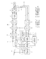
図1は、永久磁石モータ1の回転をベクトル制御するモータ制御装置50の構成をブロック図で示したものである。尚、上記コンプレッサモータも同様の構成によって制御される。ベクトル制御では、電機子巻線に流れる電流を、界磁である永久磁石の磁束方向と、それに直交する方向とに分離してそれらを独立に調整し、磁束と発生トルクとを制御する。電流制御には、モータ1の回転子と共に回転する座標系、いわゆるd−q座標系で表わした電流値が用いられるが、d軸は回転子に取り付けた永久磁石の作る磁束方向であり、q軸はd軸に直交する方向である。巻線に流れる電流のq軸成分であるq軸電流Iqは回転トルクを発生させる成分であり(トルク成分電流)、同d軸成分であるd軸電流Idは磁束を作る成分である(励磁または磁化成分電流)。
FIG. 1 is a block diagram showing the configuration of a
電流センサ51(U,V,W)は、モータ1の各相(U相、V相、W相)に流れる電流Iu、Iv、Iwを検出するセンサである。尚、電流センサ51(電流検出手段)に替えて、インバータ回路52(駆動手段)を構成する下アーム側のスイッチング素子とグランドとの間に3個のシャント抵抗を配置し、それらの端子電圧に基づいて電流Iu、Iv、Iwを検出する構成としても良い。尚、電流センサ51は、実際にはインバータ回路52の出力端子とモータ1の巻線5との間に介挿されている。
The current sensor 51 (U, V, W) is a sensor that detects currents Iu, Iv, and Iw that flow in each phase (U phase, V phase, and W phase) of the
電流センサ51により検出された電流Iu、Iv、Iwは、図示しないA/D変換器によりA/D変換されて、UVW/αβ座標変換器53により2相電流Iα、Iβに変換され、それらの2相電流Iα、Iβは、αβ/dq座標変換器54により、更にd軸電流Id,q軸電流Iqに変換される。α,βは、モータ1の固定子に固定された2軸座標系の座標軸である。このαβ/dq座標変換器54における座標変換の計算には、後述する回転子の回転位置推定値(α軸とd軸との位相差の推定値)θが用いられる。
The currents Iu, Iv, and Iw detected by the current sensor 51 are A / D converted by an A / D converter (not shown), and converted into two-phase currents Iα and Iβ by a UVW / αβ coordinate
d軸電流Id,q軸電流Iqについては、電流制御部55の減算器56d,56qにおいて、着磁電流決定部57(着磁制御手段)が出力するd軸電流指令値Idref、速度制御部58が出力するq軸電流指令値Iqrefとの偏差ΔId 、ΔIq が算出される。電流偏差ΔId,ΔIqは、比例積分器59d,59qにおいて比例積分演算され、d−q座標系で表わされた出力電圧指令値Vd、Vqが算出される。
出力電圧指令値Vd、Vqは、dq/αβ座標変換器60によりα−β座標系で表わした値に変換され、更にαβ/UVW座標変換器61により固定子の各相電圧指令値Vu、Vv、Vwに変換される。なお、dq/αβ座標変換器60における座標変換の計算にも、後述する回転子の回転位置推定値θが用いられる。
For the d-axis current Id and the q-axis current Iq, the
The output voltage command values Vd, Vq are converted into values expressed in the α-β coordinate system by the dq / αβ coordinate
各相電圧指令値Vu、Vv、VwはPWM形成部62に入力され、指令値に一致する電圧を供給するためのパルス幅変調されたゲート駆動信号が形成される。インバータ回路52は例えばIGBTなどのスイッチング素子を三相ブリッジ接続して構成され、図示しない直流電源回路より直流電圧の供給を受けるようになっている。PWM形成部62で形成されたゲート駆動信号は、インバータ回路52を構成する各スイッチング素子のゲートに与えられ、それにより各相電圧指令値Vu、Vv、Vwに一致するPWM変調された三相交流電圧が生成されてモータ1の電機子巻線に印加される。
The phase voltage command values Vu, Vv, Vw are input to the
上記の構成において、減算部56d,56qと比例積分器59d,59qとによる比例積分(PI)演算によるフィードバック制御が行なわれ、d軸電流Id、q軸電流Iqはそれぞれd軸電流指令値Idref、q軸電流指令値Iqrefに一致するように制御される。
In the above configuration, feedback control is performed by proportional integration (PI) calculation by the subtracting
速度・位置推定部63(速度・位置推定手段)は、モータ1の角速度ω,回転子の回転位置θをそれぞれ推定するもので、d軸電流Id、q軸電流Iq及びd軸出力電圧指令値Vdが入力されている。また、誘起電圧検出部65(誘起電圧検出手段)には、モータ1の回路定数(モータ定数)である電機子巻線のd軸インダクタンスLd、q軸インダクタンスLq、巻線抵抗値Rの各値が記憶されている。
The speed / position estimation unit 63 (speed / position estimation means) estimates the angular speed ω of the
速度・位置推定部63は、(1)式のd軸モータ電圧方程式を用いて、モータ1の角速度ωを推定する。
Vd=R・Id−ω・Lq・Iq …(1)
更に、角速度ωを積分し、その積分結果が回転位置推定値θとして出力される。また、角速度推定値ωは速度制御部58にも与えられる。
The speed /
Vd = R · Id−ω · Lq · Iq (1)
Further, the angular velocity ω is integrated, and the integration result is output as the rotational position estimated value θ. Further, the estimated angular velocity value ω is also given to the
また、誘起電圧検出部65は、(2)式のq軸モータ電圧方程式を用いて、モータ1の誘起電圧Eqを推定する。
Vq=R・Iq+ω・Ld・Id+Eq …(2)
誘起電圧指令決定部66(誘起電圧指令決定手段)は、インバータ回路52の出力電力を表す(3)式を変形した(4)式を用いて、モータ1の出力トルクTを演算する。
3/2・(Vq・Iq+Vd・Id)=ω・T+3/2・R(Id2+Iq2)
…(3)
T=3/(2ω)・{Vq・Iq+Vd・Id−R(Id2+Iq2)}
…(4)
ここで、(3)式の左辺はインバータ回路52の出力電圧を表し、右辺第1項はモータ1の出力を、同第2項は銅損を表している。
Moreover, the induced
Vq = R · Iq + ω · Ld · Id + Eq (2)
The induced voltage command determination unit 66 (induced voltage command determination means) calculates the output torque T of the
3/2 · (Vq · Iq + Vd · Id) = ω · T + 3/2 · R (Id 2 + Iq 2 )
... (3)
T = 3 / (2ω) · {Vq · Iq + Vd · Id−R (Id 2 + Iq 2 )}
(4)
Here, the left side of equation (3) represents the output voltage of the
そして、誘起電圧指令決定部66は、トルクTを求めると、速度・位置推定部63より得られるモータ1の角速度ωとに基づきモータ1の現在の負荷点を算出する。また、その負荷点毎にモータ1の効率が最も良くなる誘起電圧を予め求めておき、その誘起電圧を指令値Eqrefとして決定する。この決定を行う過程の詳細については後述する。
Then, when the induced voltage
着磁電流決定部57は、誘起電圧検出部65により推定された誘起電圧Eqと、誘起電圧指令決定部66により決定された誘起電圧指令Eqrefとを比較することで、モータ1の回転子を構成するアルニコ磁石9bを着磁するためのd軸電流指令値(着磁電流指令値)Idrefを決定する。
The magnetizing
速度制御部58により出力されるq軸電流指令値Iqrefは、回転子の角速度(回転速度に相当)ωを、外部から入力される角速度指令値(回転速度指令値に相当)ωrefに一致させるための電流指令値である。減算器67は、洗濯乾燥機21の制御回路部より出力される角速度指令値ωrefと角速度推定値ωとの偏差Δωを算出し、その偏差Δωは、比例積分器68によって比例積分演算が施され、その演算結果がq軸電流指令値Iqerfとして出力される。
そして、d軸電流指令値Idref、q軸電流指令値Iqrefは電流制御部55に与えられ、前述したようにモータ1のd軸電流Id、q軸電流Iqがそれらの指令値に一致するように制御される。その制御結果としての角速度推定値ωが減算器67にフィードバックされる。比例積分器68は、比例積分演算により偏差Δωをゼロに収束させる。その結果、角速度推定値ωは角速度指令値ωrefに一致するようになる。
The q-axis current command value Iqref output from the
Then, the d-axis current command value Idref and the q-axis current command value Iqref are given to the
なお、以上の構成において、電流制御部55,速度制御部58,速度・位置推定部63は、ベクトル制御手段70を構成している。また、インバータ回路52,PWM形成部62を除く部分は、制御装置50を構成するマイクロコンピュータのソフトウエアにより実現されている機能である。
In the above configuration, the
次に、上記のように永久磁石モータ1を備えたドラム式洗濯乾燥機21の作用について説明する。制御回路部がインバータ回路52を介して固定子巻線5に通電すると、電機子反作用による外部磁界(固定子巻線5を流れる電流により発生する磁界)が、回転子3の永久磁石9a,9bに作用するようになる。そして、これら永久磁石9a,9bのうち、保磁力が小さいアルニコ磁石9bの磁化状態が、この電機子反作用による外部磁界により減磁または増磁され、これにより、固定子巻線5に鎖交する磁束量(鎖交磁束量)を増減することができる。そこで、本実施例では、制御回路部は、固定子巻線5の通電を制御することにより、アルニコ磁石9bの磁化状態を運転行程(洗濯行程、脱水行程、乾燥行程)ごとに切り換えて実行する。ここで、各運転行程における動作内容について順に説明する。
Next, the operation of the drum type washer / dryer 21 provided with the
まず、洗濯行程では、制御回路部は、給水弁30を開放して水槽25内に給水を行い、続いてドラム27を回転させて洗濯を行う。この洗濯行程では、水を含んだ洗濯物をバッフル29によって掻き上げるためドラム27を高トルクで回転させる必要があるが、回転速度は低速でよい。そこで、制御回路部は、アルニコ磁石9bの磁化状態が増磁されるように、インバータ回路52による固定子巻線5の通電を制御する。これにより、固定子巻線5に作用する磁束量が多く(磁力が強く)なることから、ドラム27を高トルク低速度で回転させることができる。
First, in the washing process, the control circuit unit opens the
次に、脱水行程では、制御回路部は、排水弁31を開放して水槽25内の水を排出し、続いてドラム27を高速回転させることにより洗濯物に含まれる水分を脱水する。この脱水行程においては、脱水効率を向上するためにドラム27を高速で回転させる必要があるが、トルクは小さくてもよい。そこで、制御回路部は、アルニコ磁石9bの磁化状態が減磁されるように、インバータ回路52による固定子巻線5の通電を制御する。これにより、固定子巻線5に作用する磁束量が少なく(磁力が弱く)なることから、ドラム27を低トルク高速度で回転させることができる。
Next, in the dehydration process, the control circuit unit dehydrates moisture contained in the laundry by opening the
最後に、乾燥行程では、制御回路部は、送風ファン36およびヒートポンプ40を駆動させるとともにドラム27を回転させることにより洗濯物の乾燥を行う。この乾燥行程においては、制御回路部は、次回の洗濯行程に備えて、アルニコ磁石9bの磁化状態が増磁されるように、インバータ回路52による固定子巻線5の通電を制御する。これにより、固定子巻線5に作用する磁束量を多くした状態とすることができ、次回の洗濯行程において、ドラム27を高トルク低速度で回転させ易くすることができる。
Finally, in the drying process, the control circuit unit dries the laundry by driving the
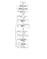
次に、上述のように洗濯乾燥機21の運転状態に応じて、アルニコ磁石9bの着磁量,モータ1の磁束量,特性を変更する場合の制御について図2乃至図4も参照して説明する。モータ1の磁束量を、d軸電流によって適切に変化させるには、通電前後の磁束量を把握することが重要である。そこで、図2に示すフローチャートに従って着磁制御を行う。
Next, the control when changing the magnetization amount of the
先ず、誘起電圧検出部65が誘起電圧Eqを演算し(ステップS1)、誘起電圧指令決定部66は、その時点のトルクT及び角速度ωとに基づいて誘起電圧指令Eqrefを決定する(ステップS2)。着磁電流決定部57は、制御回路部より磁化指令が与えられている(ON)か否かを判断し(ステップS3)、磁化指令が与えられていれば(YES)、誘起電圧指令Eqrefと誘起電圧Eqとの大小を比較する(ステップS4)。Eqref>Eqであれば(YES)、着磁電流指令Idrefの極性を(+)に設定し(ステップS5)、Eqref≦Eqであれば(NO)、着磁電流指令Idrefの極性を(−)に設定する(ステップS6)。
First, the induced
続くステップS7において、誘起電圧検出部65が演算した誘起電圧Eqが前回の値と同じであれば(YES)、着磁電流指令Idrefを所定値αだけ増加させ(ステップS8)、前回の値と異なれば(NO)そのままステップS9に移行する。尚、所定値αは毎回一定であっても、または毎回変化させても何れでも良い。ステップS9では、その時点のモータ1の回転子位置が着磁通電を行う位置であるか否かを判断し、通電位置であれば(YES)d軸電流を通電し(ステップS10)、通電位置でなければ(NO)ステップS1に戻る(CONTINUE)。
In subsequent step S7, if the induced voltage Eq calculated by the induced
図3は、図2の制御を繰り返し実行した場合の電流Id,Iq,誘起電圧Eq,誘起電圧指令Eqrefの変化を示すものである。トルク電流Iqは一定に制御され、モータ1を全界磁運転する場合、励磁電流Idはゼロに維持される。本実施例では、励磁電流Idを、アルニコ磁石9bを着磁するために使用するので、励磁電流Idはその着磁を行うタイミング(例えば電気角0°)で出力される(図3(a),(c)参照)。そして、図3(d)に示すように、誘起電圧Eq,誘起電圧指令Eqrefの差がなくなった場合に着磁処理は終了する。
FIG. 3 shows changes in currents Id, Iq, induced voltage Eq, and induced voltage command Eqref when the control of FIG. 2 is repeatedly executed. The torque current Iq is controlled to be constant, and the excitation current Id is maintained at zero when the
図4は、横軸にトルク[N・m],縦軸に回転数[rpm]をとり、一般的な洗濯機の運転状態に対応するモータの最大出力特性を示したものである。洗い運転や濯ぎ運転では、モータの負荷点はAとなり(例えばω=50rpm,T=12N・m)、低速回転で高トルク出力が要求される。一方、脱水運転では、モータの負荷点はBとなり(例えばω=1200rpm,T=2N・m)、低トルク出力で高速回転が要求される。効率最大となる誘起電圧Eqは、負荷点Aにおいて相対的に低くなり、負荷点Bにおいて相対的に高くなる。 FIG. 4 shows the maximum output characteristics of a motor corresponding to the operating state of a general washing machine, with the torque [N · m] on the horizontal axis and the rotational speed [rpm] on the vertical axis. In the washing operation and the rinsing operation, the load point of the motor is A (for example, ω = 50 rpm, T = 12 N · m), and high torque output is required at low speed rotation. On the other hand, in the dehydration operation, the load point of the motor is B (for example, ω = 1200 rpm, T = 2 N · m), and high speed rotation is required with a low torque output. The induced voltage Eq that maximizes efficiency is relatively low at the load point A and relatively high at the load point B.
ここで、ステップS2において、誘起電圧指令決定部66が誘起電圧指令Eqrefを決定する場合の原理を説明する。(4)式における右辺第2項を(銅損)として(1),(2)式を代入して変形すると(5)式となる。
T=3/(2ω)・{Vq・Iq+Vd・Id−(銅損)}
=1.5ω{(R・Iq+ω・Ld・Id+Eq)・Iq
+(R・Id−ω・Lq・Iq)・Id−(銅損)}
(銅損)=1.5ω(R・Iq2+ω・Ld・Id・Iq+Eq・Iq
+R・Id2−ω・Lq・Iq・Id)−T …(5)
モータ1の効率を最大にするには、銅損を最小にすれば良い。したがって、(5)式においてT,ω,R,Ld,Lqを与えた場合に、銅損が最小となる誘起電圧Eqを、誘起電圧指令Eqrefとして決定すれば良い。
Here, the principle when the induced voltage
T = 3 / (2ω) · {Vq · Iq + Vd · Id− (copper loss)}
= 1.5ω {(R · Iq + ω · Ld · Id + Eq) · Iq
+ (R · Id-ω · Lq · Iq) · Id- (copper loss)}
(Copper loss) = 1.5ω (R · Iq 2 + ω · Ld · Id · Iq + Eq · Iq
+ R · Id 2 −ω · Lq · Iq · Id) −T (5)
In order to maximize the efficiency of the
但し、上記の場合、q軸電流Iqの条件として「モータ1の負荷トルクを出力できること」、d軸電流Idの条件として「弱め界磁となることで直流電圧を設定値以上に上昇させないこと」を制限として加える。そして、例えば(5)式を演算することで誘起電圧指令Eqrefを決定しても良いし、データテーブル化してメモリ等に保持しておくことで決定しても良い。
例えば負荷点Bにおいてモータ1の磁束量を低減すれば、弱め界磁制御を行うd軸電流Idの通電量を低下させることが可能となったり、或いは弱め界磁制御を行わずとも、必要な回転数を得ることができるようになる。
However, in the above case, “the load torque of the
For example, if the magnetic flux amount of the
以上のように本実施例によれば、着磁電流決定部57は、ベクトル制御において得られる励磁電流Idにより電機子反作用磁界を発生させて、モータ1の回転子3を構成する低保磁力のアルニコ磁石9bの着磁量を変化させる。そして、着磁量の変化はモータ1が発生させる誘起電圧Eqの変化に反映されるので、誘起電圧Eqを検出すれば着磁量がどの程度変化したかを評価でき、モータ1の回転速度ωと出力トルクTとに基づき決定される誘起電圧指令Eqrefと、検出した誘起電圧Eqとの差を得れば、アルニコ磁石9bの着磁量をどの程度変化させれば良いのかを決定できる。したがって、要求される駆動特性に応じて着磁量を適切に変化させ、モータ1の運転効率を向上させて、モータ1を駆動制御することができる。
As described above, according to the present embodiment, the magnetizing
また、洗濯乾燥機21は、永久磁石モータ1により洗濯運転や脱水運転を行うための駆動力を発生させるので、洗濯運転において要求される低速回転・高出力トルクでの駆動特性,脱水運転において要求される高速回転・低出力トルクでの駆動特性に応じてモータ1の特性を変化させ、最適効率で運転を行うことで消費電力を低減することができる。特に脱水運転では、弱め界磁制御を行う必要をなくしたり、若しくは弱め界磁制御を最小限にしてモータ1の回転数を上昇させることができ、効率を向上させることができる。また、ヒートポンプ41を構成するコンプレッサ39を駆動する永久磁石モータについても同様に制御するので、乾燥運転を行う場合も同様の効果が得られる。
Further, since the washing / drying machine 21 generates a driving force for performing the washing operation and the dehydrating operation by the
更に、速度・位置推定部63は、d軸モータ電圧方程式を用いてモータ1の回転速度ω及び回転位置θを演算し、誘起電圧検出部65は、q軸モータ電圧方程式を用いてモータ1の誘起電圧を検出するので、簡単な計算で必要な値を得ることができる。
そして、誘起電圧指令決定部66は、モータ1の現在の運転状態に応じて、効率が最高となるように、すなわち、モータ電圧方程式である(1),(2)式並びにインバータ回路52の出力電力を表す(3)式より導出される(5)式に従い、銅損が最小となるように誘起電圧指令Eqrefを決定するので、洗濯乾燥機21の実際の運転状態に適合するようにモータ1の効率を最大化することできる。
Further, the speed /
Then, the induced voltage
(第2実施例)
図9は本発明の第2実施例を示すものであり、第1実施例と同一部分には同一符号を付して説明を省略し、以下異なる部分について説明する。第2実施例は、本発明のモータ駆動システムを空調機(エアコンディショナ)に適用した場合を示す。図9は、空調機を構成するヒートポンプを示す。ヒートポンプ71において、コンプレッサ72は圧縮部73とこれを駆動する永久磁石モータ(ブラシレスDCモータ)74とを同一の鉄製密閉容器75内に収納して構成されている。永久磁石モータ74は、第1実施例のモータ1と同様に構成されているものとする。
(Second embodiment)
FIG. 9 shows a second embodiment of the present invention. The same parts as those of the first embodiment are denoted by the same reference numerals and the description thereof is omitted. Hereinafter, different parts will be described. 2nd Example shows the case where the motor drive system of this invention is applied to an air conditioner (air conditioner). FIG. 9 shows a heat pump constituting the air conditioner. In the
コンプレッサ72は、四方弁76、室内側熱交換器77、減圧装置78、室外側熱交換器79と共に閉ループを構成するように冷媒配管によって接続されている。四方弁76は暖房運転及び冷房運転に応じて実線及び二点鎖線で示す状態に切り替えられ、コンプレッサ72の圧縮部73で圧縮された冷媒は、暖房時には室内側熱交換器77、減圧装置78、室外側熱交換器79を順に通って圧縮部73に戻り、冷房時には室外側熱交換器79、減圧装置78、室内側熱交換器77を順に通って圧縮部73に戻るように制御される。
従って、室内側熱交換器77は暖房時には凝縮器となって室内を暖め、冷房時には冷却器となって室内を冷やすこととなる。なお、室内空気及び室外空気はファン装置80及び81により夫々室内側熱交換器77及び室外側熱交換器79に送られる。以上が空調機82を構成している。
The
Therefore, the
以上のように構成される第2実施例によれば、空調機81は、本発明のモータ駆動システムを備え、永久磁石モータ74によりコンプレッサ72を駆動するようにした。したがって、例えば運転を開始した直後などに室内温度を短時間で急速に低下又は上昇させる必要があり、コンプレッサ72を高速回転させる場合にアルニコ磁石9bの磁束量を変化させて図4に示す負荷点Bに対応するように効率を最大化させ、各運転に適するようにモータ74の特性を変化させれば、消費電力を低減することができる。
According to the second embodiment configured as described above, the
本発明は上記し又は図面に記載した実施例にのみ限定されるものではなく、以下のような変形または拡張が可能である。
特許文献1に開示されているような、IPM(Interior Permanent Magnet)タイプの永久磁石モータに適用しても良い。
乾燥機能を持たない洗濯機に適用しても良い。
低保磁力永久磁石は、アルニコ磁石9bに限ることなく、インバータ回路を介して通電を行うことで発生させる磁界により着磁量が変化可能な程度に保磁力が低い永久磁石であれば材料はとはない。同様に、高保磁力永久磁石もネオジム磁石9aに限ることはない。
更に、低保磁力永久磁石の着磁量を変化させることで、要求される運転特性を満たすことができる場合は、高保磁力永久磁石は不要である。
また、洗濯機や空調機に限ることなく、低保磁力永久磁石を備えて構成されるモータの磁束量を変化させるものであれば、広く適用することができる。
The present invention is not limited to the embodiments described above or shown in the drawings, and the following modifications or expansions are possible.
The present invention may be applied to an IPM (Interior Permanent Magnet) type permanent magnet motor as disclosed in
You may apply to the washing machine which does not have a drying function.
The low coercive force permanent magnet is not limited to the
Furthermore, when the required operating characteristics can be satisfied by changing the magnetization amount of the low coercive force permanent magnet, the high coercive force permanent magnet is not necessary.
Further, the present invention is not limited to washing machines and air conditioners, and can be widely applied as long as it changes the amount of magnetic flux of a motor including a low coercive force permanent magnet.
図面中、1は永久磁石モータ、3は回転子、5は固定子巻線、9bはアルニコ磁石(低保磁力永久磁石)、21は洗濯乾燥機、39はコンプレッサ、41はヒートポンプ、51は電流センサ(電流検出手段)、50はモータ制御装置、52はインバータ回路(駆動手段)、57は着磁電流決定部(着磁制御手段)、63は速度・位置推定部(速度・位置推定手段)、65は誘起電圧検出部(誘起電圧検出手段)、66は誘起電圧指令決定部(誘起電圧指令決定手段)、70はベクトル制御手段、72はコンプレッサ、74は永久磁石モータ、82は空調機を示す。 In the drawings, 1 is a permanent magnet motor, 3 is a rotor, 5 is a stator winding, 9b is an alnico magnet (low coercive force permanent magnet), 21 is a washing dryer, 39 is a compressor, 41 is a heat pump, and 51 is an electric current. Sensor (current detection means), 50 is a motor control device, 52 is an inverter circuit (drive means), 57 is a magnetizing current determination section (magnetization control means), and 63 is a speed / position estimation section (speed / position estimation means). , 65 is an induced voltage detection unit (induced voltage detection unit), 66 is an induced voltage command determination unit (induced voltage command determination unit), 70 is a vector control unit, 72 is a compressor, 74 is a permanent magnet motor, and 82 is an air conditioner. Show.
Claims (12)
前記モータの巻線に通電を行うことで駆動する駆動手段と、
この駆動手段を介して前記モータの巻線に通電を行い、前記永久磁石の着磁量を変化させる着磁制御手段と、
前記モータに通電される電流を検出する電流検出手段と、
前記モータ電流と、前記駆動手段の出力電圧と、前記モータの定数とに基づいて、前記モータの回転速度ω及び回転位置を演算して推定する速度・位置推定手段を備え、前記駆動手段を介して前記モータをベクトル制御するベクトル制御手段と、
前記モータの回転速度ωと、前記ベクトル制御手段により求められるモータ電流Id,Iqと、前記駆動手段の出力電圧Vd,Vqと、前記モータの定数である巻線インダクタンスLd,Lq及び巻線抵抗Rとから、前記モータの誘起電圧を検出する誘起電圧検出手段と、
前記モータの回転速度ωと前記モータの出力トルクTとに基づいて、誘起電圧指令を決定する誘起電圧指令決定手段と、
前記モータの誘起電圧と、前記誘起電圧指令とに基づいて、前記着磁制御手段による通電量を決定する着磁電流決定手段とを備えたことを特徴とするモータ制御装置。 In a motor control device for controlling a permanent magnet motor in which a permanent magnet having a coercive force that is low enough to change the amount of magnetization is arranged in a rotor,
Driving means for driving by energizing the windings of the motor;
Magnetization control means for energizing the windings of the motor through the driving means and changing the magnetization amount of the permanent magnets;
Current detecting means for detecting a current supplied to the motor;
Speed / position estimation means for calculating and estimating the rotational speed ω and rotational position of the motor based on the motor current, the output voltage of the driving means, and the constant of the motor, and through the driving means Vector control means for vector controlling the motor;
The rotational speed ω of the motor, motor currents Id and Iq determined by the vector control means, output voltages Vd and Vq of the driving means, winding inductances Ld and Lq and winding resistance R as constants of the motor. And induced voltage detection means for detecting the induced voltage of the motor;
Induced voltage command determining means for determining an induced voltage command based on the rotational speed ω of the motor and the output torque T of the motor;
A motor control device comprising magnetizing current determining means for determining an energization amount by the magnetization control means based on the induced voltage of the motor and the induced voltage command.
前記誘起電圧検出手段は、q軸モータ電圧方程式を用いて前記モータの誘起電圧を検出することを特徴とする請求項1記載のモータ制御装置。 The speed / position estimation means calculates a rotational speed ω and a rotational position of the motor using a d-axis motor voltage equation,
The motor control device according to claim 1, wherein the induced voltage detection unit detects an induced voltage of the motor using a q-axis motor voltage equation.
請求項1乃至4の何れか記載のモータ制御装置とで構成されることを特徴とするモータ駆動システム。 A permanent magnet motor in which a permanent magnet having a coercive force low enough to change the amount of magnetization is arranged on the rotor;
A motor drive system comprising the motor control device according to claim 1.
前記永久磁石モータによって、洗濯運転や脱水運転を行うための駆動力を発生させるように構成されていることを特徴とする洗濯機。 A motor drive system according to claim 5,
A washing machine configured to generate a driving force for performing a washing operation or a dehydrating operation by the permanent magnet motor.
前記永久磁石モータによって、前記ヒートポンプを構成するコンプレッサを駆動することを特徴とする請求項6記載の洗濯機。 It has a function to perform a drying operation using a heat pump,
The washing machine according to claim 6, wherein a compressor constituting the heat pump is driven by the permanent magnet motor.
前記永久磁石モータによって、コンプレッサを駆動することを特徴とする空調機。 A motor drive system according to claim 5,
A compressor is driven by the permanent magnet motor.
前記モータ電流と、前記駆動手段の出力電圧と、前記モータの定数とに基づいて、前記モータの回転速度ω及び回転位置を演算して推定してベクトル制御する場合に、前記駆動手段を介して前記永久磁石の着磁量を変更する方法において、
前記モータの回転速度ωと、前記ベクトル制御で求められるモータ電流Id,Iqと、前記駆動手段の出力電圧Vd,Vqと、前記モータの定数である巻線インダクタンスLd,Lq及び巻線抵抗Rとから、前記モータの誘起電圧を検出し、
前記モータの回転速度ωと、前記モータの出力トルクTとに基づいて、誘起電圧指令を決定すると、
前記モータの誘起電圧と、前記誘起電圧指令とに基づいて、前記着磁制御手段による通電量を決定することを特徴とする永久磁石モータの着磁量変更方法。 For a permanent magnet motor in which a permanent magnet having a coercive force that is low enough to change the amount of magnetization is arranged in the rotor, a current supplied to the motor via the driving means is detected,
Based on the motor current, the output voltage of the driving means, and the constants of the motor, the rotational speed ω and the rotational position of the motor are calculated and estimated and vector control is performed. In the method of changing the magnetization amount of the permanent magnet,
The rotational speed ω of the motor, motor currents Id and Iq determined by the vector control, output voltages Vd and Vq of the driving means, winding inductances Ld and Lq and winding resistance R which are constants of the motor, From this, the induced voltage of the motor is detected,
When the induced voltage command is determined based on the rotational speed ω of the motor and the output torque T of the motor,
A method for changing the amount of magnetization of a permanent magnet motor, wherein an energization amount by the magnetization control means is determined based on the induced voltage of the motor and the induced voltage command.
Priority Applications (3)
| Application Number | Priority Date | Filing Date | Title |
|---|---|---|---|
| JP2008112437A JP5259241B2 (en) | 2008-04-23 | 2008-04-23 | Motor controller, motor drive system, washing machine, air conditioner, method of changing the amount of magnetization of a permanent magnet motor |
| CN2009101354159A CN101567659B (en) | 2008-04-23 | 2009-04-23 | Motor control device, motor drive system, and method of changing magnetization amount of permanent magnet motor |
| US12/428,840 US8129931B2 (en) | 2008-04-23 | 2009-04-23 | Motor control device, motor drive system, washing machine, air conditioner and method of changing magnetization amount of permanent magnet motor |
Applications Claiming Priority (1)
| Application Number | Priority Date | Filing Date | Title |
|---|---|---|---|
| JP2008112437A JP5259241B2 (en) | 2008-04-23 | 2008-04-23 | Motor controller, motor drive system, washing machine, air conditioner, method of changing the amount of magnetization of a permanent magnet motor |
Publications (2)
| Publication Number | Publication Date |
|---|---|
| JP2009268191A JP2009268191A (en) | 2009-11-12 |
| JP5259241B2 true JP5259241B2 (en) | 2013-08-07 |
Family
ID=41214328
Family Applications (1)
| Application Number | Title | Priority Date | Filing Date |
|---|---|---|---|
| JP2008112437A Expired - Fee Related JP5259241B2 (en) | 2008-04-23 | 2008-04-23 | Motor controller, motor drive system, washing machine, air conditioner, method of changing the amount of magnetization of a permanent magnet motor |
Country Status (3)
| Country | Link |
|---|---|
| US (1) | US8129931B2 (en) |
| JP (1) | JP5259241B2 (en) |
| CN (1) | CN101567659B (en) |
Families Citing this family (29)
| Publication number | Priority date | Publication date | Assignee | Title |
|---|---|---|---|---|
| CN105871143B (en) * | 2006-07-24 | 2018-07-20 | 株式会社东芝 | Variable magnetic flux motor drive system |
| JP4966164B2 (en) * | 2007-11-05 | 2012-07-04 | 株式会社東芝 | Washing machine |
| JP5226276B2 (en) * | 2007-11-07 | 2013-07-03 | 株式会社東芝 | Washing machine inverter device |
| JP5468306B2 (en) * | 2009-05-25 | 2014-04-09 | 株式会社東芝 | Washing machine |
| CN102025312B (en) * | 2009-09-16 | 2014-01-29 | 株式会社东芝 | Motor control device and electrical equipment |
| JP5175887B2 (en) * | 2010-03-23 | 2013-04-03 | 株式会社東芝 | Motor control device and electrical equipment |
| JP5670077B2 (en) * | 2010-03-26 | 2015-02-18 | 株式会社東芝 | Motor control device and washing machine |
| JP5341854B2 (en) * | 2010-09-30 | 2013-11-13 | 株式会社東芝 | Permanent magnet motor and washing machine |
| RU2543998C1 (en) * | 2010-12-29 | 2015-03-10 | Арчелык Аноним Ширкети | Control circuit of synchronous motor with permanent magnets |
| EP2681829B1 (en) | 2011-02-28 | 2020-07-01 | Danfoss Power Solutions (US) Company | Brushless pm machine construction enabling low coercivity magnets |
| JP2012196095A (en) * | 2011-03-17 | 2012-10-11 | Toyota Motor Corp | Rotary electric machine system |
| JP5732309B2 (en) * | 2011-04-26 | 2015-06-10 | 日立アプライアンス株式会社 | Positive displacement compressor |
| JP5915614B2 (en) * | 2013-10-09 | 2016-05-11 | 株式会社安川電機 | Current source inverter device |
| KR101613966B1 (en) * | 2014-12-29 | 2016-04-20 | 엘지전자 주식회사 | Clothes treating apparatus |
| KR101755831B1 (en) * | 2015-08-28 | 2017-07-10 | 현대자동차주식회사 | Control method of motor |
| JP6140236B2 (en) | 2015-09-30 | 2017-05-31 | ファナック株式会社 | Machine learning device and magnetizing device for electric motor |
| JP6214711B2 (en) * | 2016-04-12 | 2017-10-18 | 三菱電機株式会社 | Control device for rotating electrical machine |
| CN107086836B (en) * | 2017-05-10 | 2019-06-21 | 西北工业大学 | An Improved Field Weakening Speed Regulation Method for Permanent Magnet Synchronous Motors |
| DE102017112388A1 (en) * | 2017-06-06 | 2018-12-06 | Dr. Ing. H.C. F. Porsche Aktiengesellschaft | Method and device for operating a synchronous machine with a permanent magnet rotor |
| JP6990085B2 (en) * | 2017-10-03 | 2022-01-12 | マブチモーター株式会社 | Rotation speed calculation device |
| KR20190063197A (en) * | 2017-11-29 | 2019-06-07 | 엘지전자 주식회사 | Washing machine |
| EP3747036B1 (en) | 2018-02-02 | 2025-09-17 | Robotiq Inc. | A programmable permanent magnet actuator and a magnetic field generation apparatus and method |
| JP7308441B2 (en) | 2019-02-07 | 2023-07-14 | パナソニックIpマネジメント株式会社 | Electric tool |
| KR102759335B1 (en) * | 2019-03-15 | 2025-01-24 | 코웨이 주식회사 | Method for Recover an Error of Control Module of Multi-Function Storage System |
| CN110011586A (en) * | 2019-03-25 | 2019-07-12 | 深圳市汇川技术股份有限公司 | Demagnetization protection method, system, device and storage medium for permanent magnet synchronous motor |
| JP7123274B2 (en) * | 2019-05-16 | 2022-08-22 | デュクシオン モーターズ インコーポレイティド | Aircraft electric propulsion system and aircraft |
| US11655043B2 (en) | 2019-05-16 | 2023-05-23 | Duxion Motors, Inc. | Electric aircraft propulsion system |
| WO2020261764A1 (en) | 2019-06-28 | 2020-12-30 | パナソニックIpマネジメント株式会社 | Impact tool |
| JP2023005629A (en) * | 2021-06-29 | 2023-01-18 | 株式会社日立産機システム | Power conversion device |
Family Cites Families (13)
| Publication number | Priority date | Publication date | Assignee | Title |
|---|---|---|---|---|
| JP3488043B2 (en) * | 1997-05-26 | 2004-01-19 | 株式会社日立製作所 | Drive system with permanent magnet type synchronous generator and drive control method for electric vehicle using the same |
| JP4154149B2 (en) * | 2001-12-28 | 2008-09-24 | 株式会社東芝 | Vector control inverter device |
| JP4053968B2 (en) * | 2003-11-25 | 2008-02-27 | 三菱電機株式会社 | Synchronous motor driving device, refrigerator and air conditioner |
| JP5398103B2 (en) * | 2005-03-01 | 2014-01-29 | 株式会社東芝 | Permanent magnet rotating electric machine |
| US7304452B2 (en) * | 2005-03-11 | 2007-12-04 | Kabushiki Kaisha Toshiba | Motor control device |
| JP2007175135A (en) * | 2005-12-27 | 2007-07-12 | Matsushita Electric Ind Co Ltd | Motor drive device for washing machine or washing / drying machine |
| JP4864455B2 (en) * | 2005-12-28 | 2012-02-01 | 株式会社東芝 | Inverter device |
| JP4754379B2 (en) * | 2006-03-22 | 2011-08-24 | 本田技研工業株式会社 | Electric motor control device |
| JP4789720B2 (en) * | 2006-07-07 | 2011-10-12 | 三洋電機株式会社 | Motor control device |
| CN105871143B (en) * | 2006-07-24 | 2018-07-20 | 株式会社东芝 | Variable magnetic flux motor drive system |
| JP4936820B2 (en) * | 2006-08-10 | 2012-05-23 | 株式会社東芝 | Variable magnetic flux drive system |
| JP4800154B2 (en) * | 2006-09-01 | 2011-10-26 | 本田技研工業株式会社 | Electric motor control device |
| JP5002335B2 (en) * | 2007-05-29 | 2012-08-15 | 株式会社東芝 | Motor control device, washing machine and motor control method |
-
2008
- 2008-04-23 JP JP2008112437A patent/JP5259241B2/en not_active Expired - Fee Related
-
2009
- 2009-04-23 CN CN2009101354159A patent/CN101567659B/en not_active Expired - Fee Related
- 2009-04-23 US US12/428,840 patent/US8129931B2/en not_active Expired - Fee Related
Also Published As
| Publication number | Publication date |
|---|---|
| JP2009268191A (en) | 2009-11-12 |
| US20090267546A1 (en) | 2009-10-29 |
| CN101567659B (en) | 2012-06-20 |
| CN101567659A (en) | 2009-10-28 |
| US8129931B2 (en) | 2012-03-06 |
Similar Documents
| Publication | Publication Date | Title |
|---|---|---|
| JP5259241B2 (en) | Motor controller, motor drive system, washing machine, air conditioner, method of changing the amount of magnetization of a permanent magnet motor | |
| JP4834712B2 (en) | Motor control device, motor control system, washing machine, and method for magnetizing permanent magnet motor | |
| JP4762299B2 (en) | Drum washing machine | |
| JP5127800B2 (en) | Motor control device | |
| JP5112219B2 (en) | Permanent magnet motor, washing machine and control device | |
| US8174219B2 (en) | Motor control unit and air conditioner having the same | |
| KR101199136B1 (en) | Rotor position detecting device | |
| JP4314283B2 (en) | Washing and drying machine | |
| US20080297099A1 (en) | Motor controller, washing machine, and motor control method | |
| EP2436821A1 (en) | Washing machine | |
| JP2011066992A (en) | Motor control apparatus and washing machine | |
| JP2010220400A (en) | Motor control device, motor control system, washing machine, and method for magnetizing permanent-magnet motor | |
| JP2011188668A (en) | Motor controller and washing machine | |
| JP2010226914A (en) | Motor control device, drum-type washing machine, and permanent magnet motor magnetization control method | |
| JP4806061B2 (en) | Motor control device | |
| JP2012010589A (en) | Rotor position detection device | |
| JP5670077B2 (en) | Motor control device and washing machine | |
| JP2007029327A (en) | Motor drive device for washing and drying machine |
Legal Events
| Date | Code | Title | Description |
|---|---|---|---|
| A621 | Written request for application examination |
Free format text: JAPANESE INTERMEDIATE CODE: A621 Effective date: 20100924 |
|
| A977 | Report on retrieval |
Free format text: JAPANESE INTERMEDIATE CODE: A971007 Effective date: 20120727 |
|
| A131 | Notification of reasons for refusal |
Free format text: JAPANESE INTERMEDIATE CODE: A131 Effective date: 20120731 |
|
| A521 | Request for written amendment filed |
Free format text: JAPANESE INTERMEDIATE CODE: A523 Effective date: 20120927 |
|
| TRDD | Decision of grant or rejection written | ||
| A01 | Written decision to grant a patent or to grant a registration (utility model) |
Free format text: JAPANESE INTERMEDIATE CODE: A01 Effective date: 20130402 |
|
| A61 | First payment of annual fees (during grant procedure) |
Free format text: JAPANESE INTERMEDIATE CODE: A61 Effective date: 20130424 |
|
| FPAY | Renewal fee payment (event date is renewal date of database) |
Free format text: PAYMENT UNTIL: 20160502 Year of fee payment: 3 |
|
| R151 | Written notification of patent or utility model registration |
Ref document number: 5259241 Country of ref document: JP Free format text: JAPANESE INTERMEDIATE CODE: R151 |
|
| S111 | Request for change of ownership or part of ownership |
Free format text: JAPANESE INTERMEDIATE CODE: R313114 |
|
| R350 | Written notification of registration of transfer |
Free format text: JAPANESE INTERMEDIATE CODE: R350 |
|
| S111 | Request for change of ownership or part of ownership |
Free format text: JAPANESE INTERMEDIATE CODE: R313117 |
|
| S531 | Written request for registration of change of domicile |
Free format text: JAPANESE INTERMEDIATE CODE: R313531 |
|
| R350 | Written notification of registration of transfer |
Free format text: JAPANESE INTERMEDIATE CODE: R350 |
|
| R250 | Receipt of annual fees |
Free format text: JAPANESE INTERMEDIATE CODE: R250 |
|
| LAPS | Cancellation because of no payment of annual fees |