JP5670077B2 - Motor control device and washing machine - Google Patents
Motor control device and washing machine Download PDFInfo
- Publication number
- JP5670077B2 JP5670077B2 JP2010072171A JP2010072171A JP5670077B2 JP 5670077 B2 JP5670077 B2 JP 5670077B2 JP 2010072171 A JP2010072171 A JP 2010072171A JP 2010072171 A JP2010072171 A JP 2010072171A JP 5670077 B2 JP5670077 B2 JP 5670077B2
- Authority
- JP
- Japan
- Prior art keywords
- motor
- speed
- value
- rotation
- control device
- Prior art date
- Legal status (The legal status is an assumption and is not a legal conclusion. Google has not performed a legal analysis and makes no representation as to the accuracy of the status listed.)
- Active
Links
Images


Description
本発明は、モータのロータ位置を検出する複数の回転位置センサより出力されるセンサ信号の変化タイミングでモータの回転速度を算出して速度制御を行うモータ制御装置,及びそのモータ制御装置を備えてなる洗濯機に関する。 The present invention includes a motor control device that calculates a rotational speed of a motor at a change timing of sensor signals output from a plurality of rotational position sensors that detect a rotor position of the motor and performs speed control, and the motor control device. Relates to a washing machine.
例えば洗濯機などのように、負荷トルクの変動が大きく、それに比較して駆動系の慣性が小さいモータを制御するシステムでは速度変動が大きくなるため、稀にではあるが、運転中に短時間の回転停止が発生することがある。このような回転停止の例として、モータの駆動系が、本来は回転を継続するのに十分なトルクを出力可能であるにもかかわらず、制御系が負荷トルクの大きな変動に応答した結果、出力トルクを必要以上に低下させたことが原因となる場合がある。
図12は、例えばドラム式洗濯機のドラムが回転を開始する際に、内部の洗濯物がバッフルにより掻き揚げられる状態を示している。(a)ドラムが回転を停止しており、洗濯物がドラム内の最低位置にある状態から、(b)ドラムが回転を開始して、その回転位置が90度付近になり洗濯物がバッフルにより掻き揚げられた状態になると、モータの負荷が極めて大きくなる。
For example, in a system that controls a motor with a large load torque fluctuation and a small inertia of the drive system, such as a washing machine, the speed fluctuation is large. Stopping rotation may occur. As an example of such a rotation stop, although the motor drive system can output a torque that is normally sufficient to continue the rotation, the control system responds to a large fluctuation in the load torque, resulting in an output. It may be caused by lowering the torque more than necessary.
FIG. 12 shows a state in which the laundry inside is swept up by the baffle when the drum of the drum type washing machine starts rotating, for example. (A) From the state where the drum has stopped rotating and the laundry is at the lowest position in the drum, (b) the drum starts to rotate, and its rotational position is close to 90 degrees. When it is in the state of being lifted up, the load on the motor becomes extremely large.
モータの回転停止を防止したり回転異常を検出する技術は、従来様々なものが提案されている。例えば特許文献1には、ブラシレスモータについて3個の回転位置センサを使用する場合に、これらの取り付け位置のばらつきによって生じる各センサ信号のエッジ間隔(時間幅)の変動を吸収するため、個々のセンサ信号の半周期又は1周期に相当する時間からモータの回転速度を確定し、ばらつきを排除する技術が開示されている。また、特許文献2には、コピー機のファンモータに配置したホール素子が出力するパルス信号のパルス幅をCPUが監視することで、モータの回転異常を検出する技術が開示されている。 Various techniques have been proposed in the past for preventing the rotation of a motor from being stopped or detecting a rotation abnormality. For example, in Patent Document 1, when three rotational position sensors are used for a brushless motor, each sensor signal is absorbed in order to absorb fluctuations in the edge interval (time width) of each sensor signal caused by variations in these attachment positions. A technique is disclosed in which the rotational speed of a motor is determined from a time corresponding to a half cycle or one cycle of a signal and variation is eliminated. Japanese Patent Application Laid-Open No. 2004-228561 discloses a technique for detecting abnormal rotation of a motor by monitoring a pulse width of a pulse signal output from a hall element arranged in a fan motor of a copier.
特許文献1には、回転制御の詳細については開示が無いが、一般に、モータの回転に伴って出力されるパルス信号に基づき回転速度を検出して速度制御を行う構成では、パルス信号のエッジ入力があった瞬間に速度が決定される(例えば、特許文献1の図6参照)。したがって、エッジ入力があったタイミングでモータへの通電電流又は印加電圧が調整され、モータの出力トルクを制御して回転速度を目標値に一致させることになる。
しかしながら、例えばトルク変動が生じる直前に検出した実速度が目標値に対して大きいと判断して通電電流を低下させている状態から急激に負荷が増加すると、通電電流を増加させる時間がなく、回転速度が急低下してセンサパルスの出力が無くなることがある。このような場合は、次のセンサパルスが発生するまで回転速度の低下が検知されないため、速度制御においてモータ電流が増加することもなく、回転が停止して異常検出されることになる。したがって、負荷トルク変動が大きい場合の回転停止に対処することはできない。
Patent Document 1 does not disclose details of rotation control. However, in general, in the configuration in which the rotation speed is detected based on the pulse signal output as the motor rotates, the edge input of the pulse signal is performed. The speed is determined at the moment when there is (see, for example, FIG. 6 of Patent Document 1). Accordingly, the energization current or applied voltage to the motor is adjusted at the timing when the edge is input, and the output torque of the motor is controlled to make the rotation speed coincide with the target value.
However, for example, if the load suddenly increases from a state where the actual current detected immediately before the torque fluctuation occurs is larger than the target value and the energization current is reduced, there is no time to increase the energization current, and the rotation The speed may drop rapidly and the sensor pulse output may be lost. In such a case, since a decrease in the rotation speed is not detected until the next sensor pulse is generated, the motor current does not increase in the speed control, and the rotation stops and an abnormality is detected. Therefore, it is impossible to cope with the rotation stop when the load torque fluctuation is large.
また、特許文献2は、回転異常を検出する技術であり、一旦回転が停止した状態を検出した後にモータの再起動を行うことになるため、迅速な対応に資するものではない。
また、特許文献3の段落[0098]には、三相センサパルスエッジの出力に応じて発生する割込み回数を、マイコンが単位時間についてカウントすることでロータの回転数を計測することが開示されている。
Further,
Further, paragraph [0098] of
特許文献3の方式では、モータの回転数が単位時間毎に計測されるため、特許文献1のような問題は発生しない。ところがこの場合、上記単位時間は、三相パルスエッジの出力間隔に対して十分に長い時間としなければ、回転数の分解能が粗くなってしまう。ブラシレスDCモータについて一般的に使用されるホール素子などのセンサ数は高々3個であり、回転制御の周期が長くなり過ぎると精密な制御ができなくなる。だからと言ってロータリエンコーダのように出力パルス数が多いものを使用すると、コストアップに繋がり、製品のサイズが大型化することになる。
In the method of
本発明は上記事情に鑑みてなされたものであり、その目的は、大きな負荷トルク変動が生じたことに起因する回転が停止した場合でも、極力短時間内に再起動することができるモータ制御装置,及びそのモータ制御装置を備えてなる洗濯機を提供することにある。 The present invention has been made in view of the above circumstances, and a purpose of the present invention is to provide a motor control device that can be restarted within a short time as much as possible even when rotation caused by large load torque fluctuations has stopped. And a washing machine including the motor control device.
上記目的を達成するため、請求項1記載のモータ制御装置は、モータのロータ位置を検出する複数の回転位置センサと、
前記モータの回転中に、前記複数の回転位置センサより出力されるセンサ信号が変化するタイミングで前記モータの回転速度を算出し、算出した回転速度に基づいて前記モータの巻線に通電する電流を制御して速度制御を行い、前記センサ信号が変化しない状態が所定の監視時間以上継続すると、前記モータの巻線に通電する電流量を現状の制御値より増加させる速度制御手段とを備えたことを特徴とする。
斯様に構成すれば、駆動系の慣性が小さく、且つ一電気角周期に対して複数の回転位置センサより出力されるセンサ信号の変化回数が少ない場合でも、モータの速度制御が不安定な状態になったことを早期に検出して、モータの回転速度を上昇させることができる。
In order to achieve the above object, a motor control device according to claim 1 includes a plurality of rotational position sensors for detecting a rotor position of the motor;
During the rotation of the motor, the rotation speed of the motor is calculated at a timing when sensor signals output from the plurality of rotation position sensors change, and a current flowing through the winding of the motor is calculated based on the calculated rotation speed. Speed control means is provided for controlling the speed, and when the state in which the sensor signal does not change continues for a predetermined monitoring time or longer, the speed control means for increasing the amount of current to be supplied to the winding of the motor from the current control value. It is characterized by.
With this configuration, the motor speed control is unstable even when the inertia of the drive system is small and the number of changes in sensor signals output from a plurality of rotational position sensors is small for one electrical angle cycle. Thus, it is possible to increase the rotation speed of the motor by detecting at an early stage.
また、請求項8記載の洗濯機は、洗い及び脱水を行うための回転駆動力を発生させるモータと、請求項1ないし7の何れかに記載のモータ制御装置とを備えることを特徴とする。すなわち、洗濯機は一般に、駆動系の慣性が小さく負荷トルクの変動が大きいので、本発明を有効に適用できる。 A washing machine according to an eighth aspect includes a motor that generates a rotational driving force for performing washing and dehydration, and the motor control device according to any one of the first to seventh aspects. That is, since the washing machine generally has a small inertia of the drive system and a large fluctuation of the load torque, the present invention can be effectively applied.
請求項1記載のモータ制御装置によれば、モータの速度制御が不安定な状態になったことを早期に検出してモータの回転速度を上昇させ、速度制御を安定した状態に復帰させることができる。
請求項8記載の洗濯機によれば、回転槽内の洗濯物の量や分布状態に応じて負荷トルクが大きく変動する場合でも、モータの回転が停止する期間を極力減少させて運転時間を短縮することができる。
According to the motor control device of the first aspect, it is possible to detect at an early stage that the speed control of the motor has become unstable, increase the rotational speed of the motor, and return the speed control to a stable state. it can.
According to the washing machine of
(第1実施例)
以下、第1実施例について図1ないし図8を参照して説明する。図8は、ドラム式洗濯乾燥機の構成を示す縦断側面図である。外箱1は前板,後板,左側板,右側板,底板及び天板を有して中空状をなしており、外箱1の前板には貫通孔状の出入口2が形成されている。この外箱1の前板には扉3が装着されている。この扉3は使用者が前方から閉鎖状態および開放状態相互間で操作可能なもので、扉3の閉鎖状態では出入口2が閉鎖され、扉3の開放状態では出入口2が開放される。外箱1の内部には水受槽4が固定されている。この水受槽4は後面が閉鎖された円筒状をなすもので、軸心線CLが前から後に向けて下降する傾斜状態に配置されている。この水受槽4は前面が開口するものであり、扉3の閉鎖状態では扉3が水受槽4の前面を気密状態に閉鎖する。
(First embodiment)
Hereinafter, a first embodiment will be described with reference to FIGS. FIG. 8 is a longitudinal side view showing the configuration of the drum type washing and drying machine. The outer box 1 has a front plate, a rear plate, a left side plate, a right side plate, a bottom plate, and a top plate and has a hollow shape. A front plate of the outer box 1 is formed with a through-hole-
水受槽4の後板には、水受槽4の外部に位置してドラムモータ5が固定されている。このドラムモータ5はブラシレスDCモータからなり、ドラムモータ5の回転軸6は水受槽4の内部に突出している。この回転軸6は水受槽4の軸心線CLに重ねて配置され、回転軸6には水受槽4の内部に位置してドラム(回転槽)7が固定されている。このドラム7は後面が閉鎖された円筒状をなすもので、ドラムモータ5の運転状態に伴い回転軸6と一体的に回転する。このドラム7の前面は水受槽4の前面を介して出入口2に後方から対向しており、ドラム7の内部には、扉3が開放された状態で前方から出入口2と水受槽4の前面とドラム7の前面を通して洗濯物が出し入れされる。
A
ドラム7には、複数の貫通孔8が形成されており、ドラム7の内部空間は複数の貫通孔8のそれぞれを通して水受槽4の内部空間に接続されている。このドラム7の内周面には複数のバッフル9が固定されている。これら複数のバッフル9のそれぞれは、ドラム7の回転により軸心線CLを中心に円周方向へ移動するものであり、ドラム7内の洗濯物は、複数のバッフル9のそれぞれに引掛かりながら円周方向へ移動した後に重力で落下することで撹拌される。
A plurality of through
外箱1の内部には、給水弁10が固定されている。この給水弁10は入口および出口を有し、給水弁10の入口は水道の蛇口に接続されている。この給水弁10は図示しない給水弁モータを駆動源とするもので、給水弁10の出口は給水弁モータの回転量に応じて開放状態および閉鎖状態相互間で切換えられる。この給水弁10の出口は、注水ケース11に接続されており、給水弁10が開放状態になると水道水が給水弁10を通して注水ケース11内に注入される。この注水ケース11は、外箱1の内部に水受槽4より高所に位置して固定されたもので、筒状の注水口12を有している。この注水口12は水受槽4の内部に挿入されており、給水弁10から注水ケース11内に注入された水道水は、注水口12から水受槽4の内部に注入される。
A
水受槽4には、最底部に位置して排水管13の上端部が接続されており、排水管13には排水弁14が介在している。この排水弁14は図示しない排水弁モータを駆動源とするもので、排水弁モータの回転量に応じて開放状態および閉鎖状態相互間で切換えられる。この排水弁14の閉鎖状態では注水口12から水受槽4内に注入された水道水が水受槽4内に貯留され、排水弁14の開放状態では水受槽4内の水道水が排水管13を通して水受槽4の外部に排出される。
An upper end portion of a
外箱1の底板には、水受槽4の下方に位置してメインダクト15が固定されている。このメインダクト15は前後方向へ指向する筒状をなし、メインダクト15の前端部には前ダクト16の下端部が接続されている。この前ダクト16は上下方向へ指向する筒状をなすものであり、前ダクト16の上端部は、水受槽4の内部空間に水受槽4の前端部で接続されている。メインダクト15の後端部にはファンケーシング17が固定されている。このファンケーシング17は貫通孔状の吸気口18および筒状の排気口19を有するものであり、ファンケーシング17の内部空間は吸気口18を介してメインダクト15の内部空間に接続されている。
A
ファンケーシング17には、ファンケーシング17の外部に位置してファンモータ20が固定されている。ファンモータ20はファンケーシング17の内部に突出する回転軸21を有し、回転軸21にはファンケーシング17の内部に位置してファン22が固定されている。このファン22は軸方向から空気を吸込んで径方向へ吐出する遠心式のものであり、ファンケーシング17の吸気口18は、ファン22にその軸方向から対向し、ファンケーシング17の排気口19は、ファン22にその径方向から対向している。
A
ファンケーシング17の排気口19には、後ダクト23の下端部が接続されている。この後ダクト23は上下方向へ指向する筒状をなすものであり、後ダクト23の上端部は水受槽4の内部空間に水受槽4の後端部で接続されている。これら後ダクト23,ファンケーシング17,メインダクト15,前ダクト16及び水受槽4は、水受槽4の内部空間を始点,終点それぞれとする環状の循環ダクト24を構成しており、扉3の閉鎖状態でファンモータ20が運転されている場合は、ファン22が一定方向へ回転することにより、水受槽4内の空気が前ダクト16内からメインダクト15内を通してファンケーシング17内に吸引され、ファンケーシング17内から後ダクト23内を通して水受槽4内に戻される。
The lower end of the
外箱1の内部には、コンプレッサ(圧縮機)25が固定されている。このコンプレッサ25は循環ダクト24の外部に配置されたものであり、冷媒を吐出する吐出口および冷媒を吸込む吸込口を有している。このコンプレッサ25は、内蔵されている図示しないコンプレッサモータを駆動源とするもので、コンプレッサモータも、やはりブラシレスDCモータで構成されている。
メインダクト15の内部には、コンデンサ(凝縮器)26が固定されている。このコンデンサ26は空気を加熱するものであり、蛇行状に曲折する1本の冷媒管27の外周面に板状をなす複数の加熱フィン31のそれぞれを接触状態で固定して構成されている。このコンデンサ26の冷媒管27はコンプレッサ25の吐出口に接続されており、コンプレッサモータの運転状態では、コンプレッサ25の吐出口から吐出された冷媒がコンデンサ26の冷媒管27内に進入する。
A compressor (compressor) 25 is fixed inside the outer box 1. The
A condenser (condenser) 26 is fixed inside the
外箱1の内部には、図示しないキャピラリーチューブ(減圧器)が固定されている。このキャピラリーチューブはコンデンサ26の冷媒管27に接続されて循環ダクト24の外部に配置され、コンデンサ26の下流側で冷媒の流れを絞るものであり、1本のパイプから構成されている。尚、キャピラリチューブに替えて電子式膨張弁〔PMV:Pulse Motor Valve〕を用いても良い。メインダクト15の内部には、エバポレータ28が固定されている。このエバポレータ28は空気を冷却するものであり、コンデンサ26よりも空気の流れの上流側に配置されている。尚、コンプレッサ25,コンデンサ26,エバポレータ28及び冷媒管27やキャピラリーチューブなど、これらを接続する配管等によってヒートポンプ29が構成されている。
A capillary tube (decompressor) (not shown) is fixed inside the outer box 1. The capillary tube is connected to the
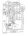
図6は、ドラムモータ5の駆動制御系を概略的に示すものである。インバータ回路(PWM制御方式インバータ)31は、6個のIGBT(半導体スイッチング素子)32a〜32fを三相ブリッジ接続して構成されており、各IGBT32a〜32fのコレクタ−エミッタ間には、フライホイールダイオード33a〜33fが接続されている。
下アーム側のIGBT32d、32e、32fのエミッタは、シャント抵抗(電流検出素子)34u、34v、34wを介してグランドに接続されている。また、IGBT32d、32e、32fのエミッタとシャント抵抗34u、34v、34wとの共通接続点は、分圧抵抗(分圧比1:1)からなるレベルシフト回路35を介して増幅回路部36の各入力端子に接続されている。尚、ドラムモータ5の巻線5u〜5wには最大で15A程度流れるので、シャント抵抗34u〜34wの抵抗値は、例えば0.033Ωに設定されている。また、レベルシフト回路35を構成する分圧抵抗の抵抗値は、例えばそれぞれ1kΩに設定されている。
FIG. 6 schematically shows a drive control system of the
The emitters of the lower
インバータ回路31の入力側には駆動用電源回路37が接続されている。駆動用電源回路37は、100Vの商用交流電源38を、ダイオードブリッジで構成される全波整流回路39及び直列接続された2個のコンデンサ40a、40bにより倍電圧全波整流し、約280Vの直流電圧をインバータ回路31に供給する。インバータ回路31の各相出力端子は、ドラムモータ5の各相巻線5u、5v、5wに接続されている。
A driving
制御回路(速度制御手段)30は、増幅回路部36を介して得られるモータ5の巻線5u〜5wに流れる各相の電流を、A/D変換回路(ADC)30aによりA/D変換して読み込むと、その電流値と、インバータの出力電圧と、モータ定数(巻線の抵抗値及びインダクタンス)とに基づいて2次側の回転磁界の位相θ及び回転角速度ωを推定すると共に、三相電流を直交座標変換及びd−q(direct−quadrature) 座標変換して励磁電流成分Id,トルク電流成分Iqを得る。
そして、制御回路30は外部より速度指令が与えられると、推定した位相θ及び回転角速度ω並びに電流成分Id、Iqに基づいて電流指令Idref,Iqrefを生成し、それを電圧指令Vd、Vqに変換すると直交座標変換及び三相座標変換を行なう。最終的には、駆動信号がPWM信号として生成され、インバータ回路31を介してモータ5の巻線5u〜5wに出力される。
The control circuit (speed control means) 30 A / D converts the current of each phase flowing through the
When a speed command is given from the outside, the
第1電源回路41は、インバータ回路31に供給される約280Vの駆動用電源を降圧して16Vの制御用電源を生成して駆動回路42及び高圧ドライブ回路43に供給する。また、第2電源回路44も、上記駆動用電源を降圧して3.3V電源を生成し、制御回路30及び増幅回路部36に供給する。高圧ドライバ回路43は、インバータ回路31における上アーム側のIGBT32a〜32cを駆動するために配置されている。
The first
また、ドラムモータ5のロータには、起動時に使用するための例えばホールICで構成されるホールセンサ45(u,v,w)が配置されており、ホールセンサ45(回転位置センサ,位置検出手段)が出力するロータの位置信号;センサ信号Hu,Hv,Hwは、制御回路30に与えられている。すなわち、ドラムモータ5の起動時において、ロータ位置の推定が可能となる回転速度(例えば、約30rpm)まではホールセンサ45を使用してベクトル制御を行い、上記回転速度に達した以降は、ホールセンサ45を使用しないセンサレスベクトル制御に切替える。そして、コンプレッサモータについては、具体的には図示しないが、ドラムモータ5の駆動系とほぼ対称な構成が配置されている。
The rotor of the
また、電源回路37の出力端子とグランドとの間には、抵抗素子46a,46bの直列回路が接続されており、それらの共通接続点は、制御回路30の入力端子に接続されている。制御回路30は、抵抗素子46a,46bにより分圧されたインバータ回路31の入力電圧を読み込み、PWM信号デューティを決定するための基準とする。その他、制御回路30は、例えばドアロック制御回路や乾燥用ファンモータ等の各種電装品47を制御したり、前述した表示・操作用基板48との間で操作信号や制御信号等の入出力を行うようになっている。更に、制御回路30は、S/N比を向上させるため、通常のモータ制御を行う場合は増幅回路部36の増幅率を大きくし、後述するようにドラムモータ5のロータに配置されている磁石の着磁制御を行う場合は増幅率を小さくするように切替える。また、増幅回路部36に内蔵されている過電流判別機能が過電流検出信号を出力した場合には、それに応じた保護動作を行う。
Further, a series circuit of
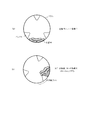
図5は、アウタロータ型のドラムモータ5(永久磁石モータ)のロータの構成を示す平面図である。ドラムモータ5は、ステータ51と、その外周に配置されるロータ52とで構成されている。ステータ51は、ステータコア53とステータ巻線5(u,v,w)とから構成されている。ステータコア53は、打ち抜き形成した軟磁性体であるケイ素鋼板を多数枚積層した後かしめて構成したもので、環状のヨーク部53aと、当該ヨーク部53aの外周部から放射状に突出する多数のティース部53bとを有している。ステータコア53の表面は、各ティース部53bの先端面を除き、PET樹脂(モールド樹脂)により覆われている。
また、このPET樹脂から成る複数の取付部54が、ステータ51の内周部に一体的に成形されている。これら取付部54には複数のねじ穴54aが設けられており、これら取付部54をねじ止めすることで、ステータ51が、この場合、ドラム式洗濯乾燥機の水受槽4の背面に固着される。ステータ巻線5(u,v,w)は三相からなり、各ティース部53bに巻装されている。
FIG. 5 is a plan view showing the configuration of the rotor of the outer rotor type drum motor 5 (permanent magnet motor). The
A plurality of mounting
ロータ52は、フレーム55とロータコア8と複数の永久磁石9とを図示しないモールド樹脂により一体化した構成となっている。フレーム55は、磁性体である例えば鉄板をプレス加工することにより扁平な有底円筒状に形成したものである。ロータコア56は、ほぼ環状に打ち抜き形成した軟磁性体であるケイ素鋼板を多数枚積層してかしめて構成したもので、フレーム55の内周部に配置されている。このロータコア56の内周面(ステータ2の外周面(ステータコア53の外周面)と対向し当該ステータ2との間に空隙を形成する面)は、内方に向けて円弧状に突出する複数の凸部(磁極チップ)56aを有した凹凸状に形成されている。
The
これら複数の凸部56aの内部には、ロータコア56を軸方向(ケイ素鋼板の積層方向)に貫通する矩形状の挿入穴が形成されており、これら複数の挿入穴がロータコア56において環状に配置された構成となっている。永久磁石57は、挿入穴に挿入された矩形状のネオジム磁石57a(高保磁力永久磁石)と、同じく矩形状のサマリウム・コバルト磁石(以下、サマコバ磁石と称す)57b(低保磁力永久磁石)とから構成されている。この場合、ネオジム磁石57aの保磁力は約700k〜900kA/m、サマコバ磁石57bの保磁力は約100k〜200kA/mである。永久磁石57は全数48であり、それらの内6個がサマコバ磁石57bであり、42個がネオジム磁石57aとなっている。
A rectangular insertion hole that penetrates the
図6では、サマコバ磁石57bが配置されている位置にA〜Fを付している。A−B間に配置されているネオジム磁石57aは5個,B−C間に配置されているネオジム磁石57aは9個,C−D間に配置されているネオジム磁石57aは5個,D−E間に配置されているネオジム磁石57aは9個,E−F間に配置されているネオジム磁石57aは5個,F−A間に配置されているネオジム磁石57aは9個となっている。この配置形態は、同じ相について発生する誘起電圧の平均値を何れも同じ値にすることで、コギングトルクの発生を抑制するようにしたものである。そして、ドラムモータ5は、48極/36スロット構成となっており、3スロット当たりでは4極が対応する(4極/3スロット)。
In FIG. 6, AF is attached | subjected to the position where the
尚、ネオジム磁石57aが高保磁力であり、サマコバ磁石57bが低保磁力であるというのは、後述するようにステータ51を介して着磁電流を通電した場合に、サマコバ磁石57bの着磁量を変化させることができる程度の電流ではネオジム磁石57aの着磁量が変化しないという基準において、前者を高保磁力,後者を低保磁力と称している。
The
図7は、制御回路30が、ドラムモータ5(並びに圧縮機モータ)について行なうセンサレスベクトル制御の機能ブロックを示す図である。この構成は、例えば特開2003−181187号公報などに開示されているものと同様であり、ここでは概略的に説明する。尚、図7において、(α,β)はドラムモータ5の各相に対応する電気角120度間隔の三相(UVW)座標系を直交変換した直交座標系を示し、(d,q)は、ドラムモータ5のロータの回転に伴い回転している2次磁束の座標系を示す。
FIG. 7 is a diagram showing functional blocks of sensorless vector control performed by the
減算器62には、速度指令出力部61より目標速度指令ωrefが被減算値として、エスティメータ(Estimator) 63により検出されたドラムモータ5の検出速度ωが減算値として与えられ、減算器62の減算結果は、速度PI(Proportional-Integral) 制御部65に与えられる。速度PI制御部65は、目標速度指令ωref と検出速度ωとの差分量に基づいてPI(比例積分)制御を行い、q軸電流指令値Iqrefとd軸電流指令値Idrefとを生成して減算器66q、66dに被減算値として夫々出力する。減算器66q、66dには、αβ/dq変換部67より出力されるq軸電流値Iq、d軸電流値Idが減算値として夫々与えられ、減算結果は、電流PI制御部68q、68dに夫々与えられる。尚、速度PI制御部65における制御周期は1m秒に設定されている。
The
電流PI制御部68q、68dは、q軸電流指令値Iqrefとd軸電流指令値Idrefとの差分量に基づいてPI制御を行い、q軸電圧指令値Vq及びd軸電圧指令値Vdを生成してdq/αβ変換部69に出力する。dq/αβ変換部69には、エスティメータ63によって検出された2次磁束の回転位相角(ロータ位置角)θが与えられ、その回転位相角θに基づいて電圧指令値Vd、Vqを電圧指令値Vα、Vβに変換する。
The
dq/αβ変換部69が出力する電圧指令値Vα、Vβは、αβ/UVW変換部70により三相の電圧指令値Vu、Vv、Vwに変換されて出力する。電圧指令値Vu、Vv、Vwは、切換スイッチ71u、71v、71wの一方の固定接点71ua、71va、71waに与えられ、他方の固定接点71ub、71vb、71wbには、初期パターン出力部76より出力される電圧指令値Vus、Vvs、Vwsが与えられる。切換スイッチ71u、71v、71wの可動接点71uc、71vc、71wcは、PWM形成部73の入力端子に接続されている。
PWM形成部73は、電圧指令値Vus、Vvs、Vws又はVu、Vv、Vwに基づいて15.6kHzのキャリア(三角波)を変調した各相のPWM信号Vup(+,-) 、Vvp(+,-) 、Vwp(+,-) をインバータ回路31に出力する。PWM信号Vup〜Vwpは、例えばドラムモータ5の各相巻線5u,5v,5wに正弦波状の電流が通電されるよう、正弦波に基づいた電圧振幅に対応するパルス幅の信号として出力される。
The voltage command values Vα and Vβ output from the dq /
The
A/D変換回路30aは、IGBT33d〜33fのエミッタに現れる電圧信号をA/D変換した電流データIau、Iav、IawをUVW/αβ変換部75に出力する。UVW/αβ変換部75は、三相の電流データIau、Iav、Iawを所定の演算式に従って直交座標系の2軸電流データIα、Iβに変換する。そして、2軸電流データIα、Iβをαβ/dq変換部67に出力する。
αβ/dq変換部67は、ベクトル制御時にはエスティメータ63よりドラムモータ5のロータ位置角θを得ることで、所定の演算式に従って2軸電流データIα、Iβを回転座標系(d,q)上のd軸電流値Id、q軸電流値Iqに変換すると、それらを前述のようにエスティメータ63及び減算器66d、66qに出力する。
The A /
The αβ /
エスティメータ63は、q軸電圧指令値Vq、d軸電圧指令値Vd、q軸電流値Iq、d軸電流値Idに基づいてロータの位置角θ及び回転速度ωを推定し、各部に出力する。ここで、ドラムモータ5は、起動時には、初期パターン出力部76による起動パターンが印加され強制転流が行われる。その後、ホールセンサ45によりセンサ信号に基づきベクトル制御を行うと、エスティメータ63が起動されてドラムモータ5のロータの位置角θ及び回転速度ωが推定されるセンサレスベクトル制御に移行する。尚、圧縮機モータの場合は、強制転流からセンサレスベクトル制御に移行する。
The
切換え制御部77は、PWM形成部73より与えられるPMW信号のデューティ情報に基づいて切換スイッチ71の切換えを制御する。尚、以上の構成において、インバータ回路31を除く構成は、制御回路30のソフトウエアによって実現されている機能をブロック化したものである。ベクトル制御における電流制御周期は例えば128μ秒に設定されている。但し、PWM搬送波周期は、ドラムモータ5側が64μ秒,圧縮機モータ側が128μ秒となっている。そして、制御回路30とインバータ回路31とがインバータ装置99を構成している。
The switching control unit 77 controls switching of the
次に、ドラムモータ5を備えたドラム式洗濯乾燥機の作用について説明する。制御回路30がインバータ回路31によりステータ巻線5u,5v,5wに通電すると、電機子反作用による外部磁界(ステータ巻線5u,5v,5wを流れる電流により発生する磁界)が、ロータ52の永久磁石57a,57bに作用する。そして、保磁力が小さいサマコバ磁石57bの磁化状態が、上記外部磁界により減磁または増磁され、その結果、ステータ巻線5u,5v,5wに鎖交する磁束量(鎖交磁束量)が増減される。
Next, the operation of the drum type washer / dryer provided with the
洗濯運転では、制御回路30は、給水弁10を開放して水受槽4内に給水を行い、続いてドラム7を回転させて洗濯を行う。この場合、サマコバ磁石57bの磁化状態を増磁させる。これにより、ステータ巻線5u,5v,5wに作用する磁束量が多く(磁力が強く)なるので、ドラム7を高トルク・低速度で回転させるのに適した特性となる。但し、サマコバ磁石57bを最大限に着磁した場合の磁力は、ネオジム磁石57aの磁力の90%程度となるため、両者の磁力には若干の差が生じる。
In the washing operation, the
脱水運転では、制御回路30は、排水弁14を開放して水受槽4内の水を排出し、続いてドラム7を高速回転させて洗濯物に含まれる水分を脱水する。この場合、サマコバ磁石57bの磁化状態を減磁させる。これにより、ステータ巻線5u,5v,5wに作用する磁束量が少なく(磁力が弱く)なることから、ドラム7を低トルク・高速度で回転させるのに適した特性となる。最後に、乾燥運転では、制御回路30は、送風ファン22およびヒートポンプ29を駆動させると共にドラム7を回転させて洗濯物の乾燥を行う。この場合、次回の洗濯運転に備えてサマコバ磁石57bの磁化状態を増磁させる。
In the dehydration operation, the
そして、サマコバ磁石57bを減磁させた状態では、図5(b)に示すように、ホールセンサ45がサマコバ磁石57bの位置で検出する磁束が弱まるため、出力するセンサ信号波形のパルス幅が変化する場合がある。すると、センサ信号のエッジ間隔に基づいて検出される回転速度が一時的に速くなったとみなされるため、速度制御に乱れが生じやすくなる。
Then, in the state in which the
次に、本実施例の作用について図1ないし図4を参照して説明する。図1は、制御回路30による制御内容を示すフローチャートであり、例えば1m秒の周期で実行される。制御回路30は、先ずホールセンサ45u,45v,45wにより出力されるセンサ信号Hu,Hv,Hwを参照し、メモリ等の記憶手段に記憶されている1周期前のセンサ信号Hu,Hv,Hwの各レベルが示す組み合わせパターン(状態)と、今回の組み合わせパターンとが異なっているか否かを判断する(ステップS1)。ここで、両者のパターンが同じである場合は(NO)、電気角60°毎に生じる何れかのセンサ信号のエッジを跨ぐ変化が生じていないことを示すので、hall_cnt変数をインクリメントしてから(ステップS13)ステップS8に移行する。
Next, the operation of this embodiment will be described with reference to FIGS. FIG. 1 is a flowchart showing the contents of control by the
一方、ステップS1において、1周期前のセンサパターンと、今回のパターンとが異なっている場合は(YES)、双方のパターンを比較して、ドラムモータ5の回転方向並びにセンサ信号自体について異常をチェックする(ステップS2)。すなわち、図4に示すように、センサ信号Hu,Hv,Hwは、ドラムモータ5の回転方向に応じて電気角60°毎に一定のパターン(例えば正転の場合;A→B→C→D→E→F→A→B→…)で変化を繰り返すからである。
On the other hand, if the sensor pattern in the previous cycle is different from the current pattern in step S1 (YES), both patterns are compared to check the rotation direction of the
ステップS3において異常がなければ(YES)、その時点のドラムモータ5の回転速度(ω)を、予め定めた定数をhall_cnt変数のカウント値で除して求め(ステップS4)、その回転速度(ω)に基づいて速度制御を行う(ステップS5)。すなわち、ステップS4で得られるhall_cnt変数のカウント値は、電気角60°の間隔が何m秒であったかを示している。したがって、回転速度(ω)を[rpm]で得るとすれば、
ω=60・1000/(144・hall_cnt)[rpm] …(1)
となる。尚、このフローチャートにおける回転速度(ω)は単位を[rpm]として示すが、ベクトル制御のブロック図に表わされている回転速度ωは角速度[rad/s]である。
また、図4(b)には、センサ信号Hu,Hv,Hwの各エッジのタイミングで回転速度(ω)が検出され、目標速度ωrefに追従するように速度・電流が制御される状態が示されている。
If there is no abnormality in step S3 (YES), the rotational speed (ω) of the
ω = 60 · 1000 / (144 · hall_cnt) [rpm] (1)
It becomes. Note that the rotational speed (ω) in this flowchart is expressed in units of [rpm], but the rotational speed ω shown in the block diagram of the vector control is an angular speed [rad / s].
FIG. 4B shows a state in which the rotational speed (ω) is detected at the timing of each edge of the sensor signals Hu, Hv, and Hw, and the speed and current are controlled so as to follow the target speed ωref. Has been.
一方、ステップS3において異常があった場合、すなわち、ドラムモータ5の回転方向に応じたセンサ信号の出力パターンが所期通りでない場合は(NO)異常フラグをセットする(ステップS14)。この場合、例えばホールセンサ45が故障したり、センサ信号の伝送線が断線する等の異常が発生したことが想定されるので、図1の処理を終了した後、異常発生を報知(例えば警告音の出力や表示部における表示)する等の異常処理を行うようにする。
On the other hand, if there is an abnormality in step S3, that is, if the output pattern of the sensor signal corresponding to the rotation direction of the
図2は、ステップS5における「速度制御」の処理内容を示すフローチャートである。この処理は、図7のブロック図では速度PI制御部65において行われる。先ず速度指令値ωrefとステップS4で得た回転速度(ω)との差分を、偏差Omega_devとして求める(ステップS21)。そして、前回の制御で用いたq軸電流指令値の積分項に、偏差Omega_devに定数を乗じたものを加えて今回の積分項を求める(ステップS22)。
電流指令値(積分項)←(Omega_dev×定数)+電流指令値(積分項)…(2)
続いて、ステップS22で求めた今回の積分項に、偏差Omega_devに定数を乗じたものを加えて今回の比例項を求める(ステップS23)。
電流指令値(比例項)←(Omega_dev×定数)+電流指令値(積分項)…(3)
速度PI制御部65より出力されるq軸電流指令値Iqrefは、上記積分項と比例項との和として出力される。
FIG. 2 is a flowchart showing the processing content of “speed control” in step S5. This processing is performed in the speed
Current command value (integral term) ← (Omega_dev x constant) + current command value (integral term) (2)
Subsequently, the current proportional term is obtained by adding the current integral term obtained in step S22 to the deviation Omega_dev multiplied by a constant (step S23).
Current command value (proportional term) ← (Omega_dev x constant) + current command value (integral term) (3)
The q-axis current command value Iqref output from the speed
再び、図1を参照する。ステップS5で速度制御を行うと、hall_cnt変数のカウント値を「退避値」として退避させてから(ステップS6)、hall_cnt変数をクリアする(ステップS7)。次のステップS8では、hall_cnt変数が「200」(0.2sに相当,監視時間)を超えたか否かを判断するが、ステップS7を経過した後では当然「NO」と判断され、処理を終了する。以上の処理の流れは、ドラムモータ5の回転が正常な場合である。
Reference is again made to FIG. When speed control is performed in step S5, the hall_cnt variable is cleared (step S6) after the count value of the hall_cnt variable is saved as a “save value” (step S7). In the next step S8, it is determined whether or not the hall_cnt variable has exceeded “200” (corresponding to 0.2 s, monitoring time). However, after step S7, it is naturally determined “NO” and the process ends. To do. The above processing flow is when the
図12で示したような負荷トルクの急変動が生じた場合に、ドラムモータ5の制御が不安定になり回転が停止しそうになると、センサ信号Hu,Hv,Hwのエッジ間隔が伸びることになる。すると、ステップS1で「NO」と判断する回数が増加して、hall_cnt変数がステップS13でインクリメントされ続ける。その結果、ステップS8においてhall_cnt変数が「200」を超えて「YES」と判断するとステップS9に移行する。尚、ステップS8において「YES」と判断するケースは、ドラムモータ5の回転数が、
ω=60・1000/(144・200)≒2.08[rpm] …(4)
となる場合であり、極めて低速で回転している状態に相当する。
When a sudden fluctuation of the load torque as shown in FIG. 12 occurs, if the control of the
ω = 60 · 1000 / (144 · 200) ≈2.08 [rpm] (4)
This corresponds to a state of rotating at a very low speed.
ステップS9では、現在のhall_cnt変数の値を、速度制御が正常な場合にステップS6で退避させたhall_cnt変数の値と比較し、前者が退避値を超えていれば(YES)ステップS10に移行する。ステップS9での判断は、以下の(5)式における第2項が負の値になることを回避するために行うもので、「NO」と判断した場合はそのまま処理を終了する。 In step S9, the value of the current hall_cnt variable is compared with the value of the hall_cnt variable saved in step S6 when the speed control is normal. If the former exceeds the saved value (YES), the process proceeds to step S10. . The determination in step S9 is performed in order to avoid that the second term in the following equation (5) becomes a negative value. If it is determined “NO”, the processing is ended as it is.
ステップS10に移行した場合は、速度制御が異常となりドラムモータ5の回転が停止しそうな状況にあると判断される。そこで、ここでは、ステップS22の計算で使用されるq軸電流の指令値(積分項)を、以下のように決定してドラムモータ5に対する通電電流量を増加させる。
電流指令値(積分項)←電流指令値(積分項)
+(hall_cnt変数−退避値)×定数 …(5)
すなわち、hall_cnt変数と退避値との差分に定数を乗じた値を加える。そして、(5)式で求めた電流指令値(積分項)が予め定めた最大値を超えている場合は(ステップS11:YES)、電流指令値(積分項)を上記最大値に置き換えるように制限をかける(ステップS12)。
When the process proceeds to step S10, it is determined that the speed control is abnormal and the rotation of the
Current command value (integral term) ← Current command value (integral term)
+ (Hall_cnt variable-save value) x constant (5)
That is, a value obtained by multiplying the difference between the hall_cnt variable and the saved value by a constant is added. When the current command value (integral term) obtained by the equation (5) exceeds a predetermined maximum value (step S11: YES), the current command value (integral term) is replaced with the maximum value. Restriction is applied (step S12).
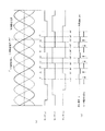
ここで、図3は、(a)ホールセンサ45(u,v,w)の各センサ信号,(b)q軸電流指令値Iqref,(c)q軸電流Iqの変化例であり、図1のステップS9で「YES」と判断した場合に相当する処理を示すタイミングチャートである。但し、(a)に示すセンサ信号が変化しない期間(無変化期間)を監視する時間は、ステップS8のように0.2秒に設定したイメージではなく、例えばステップS6の「退避値」を過去複数回分記憶しておき、それらの平均値に適当な余裕度αを加えたものとして設定した場合である。 Here, FIG. 3 is a variation example of (a) each sensor signal of the hall sensor 45 (u, v, w), (b) q-axis current command value Iqref, (c) q-axis current Iq. It is a timing chart which shows the process corresponded when it is judged as "YES" in step S9. However, the time for monitoring the period in which the sensor signal does not change (non-change period) shown in (a) is not the image set to 0.2 seconds as in step S8. For example, the “evacuation value” in step S6 is the past. This is a case where a plurality of times are stored, and the average value thereof is set as an appropriate margin α.
すなわち、この場合の監視時間は、センサ信号Hu〜Hwが前回変化したタイミングで得られたドラムモータ5の回転速度(ω)に相当する退避値に応じてダイナミックに設定され、換言すれば、少なくとも直前の値検出速度(ω)を含む過去の検出速度(ω)に基づいて期待される次のパルス発生間隔に対応する。そして、図3(a)に示すように、上記無変化期間が{(退避値の平均値)+α}よりも長くなると、(b)そこからステップS10〜S12の処理によりq軸電流指令値Iqrefが単調に増加するようになり(c)q軸電流Iqが上昇する。その結果、(a)ドラムモータ5が再び正常に回転するようになっている。
That is, the monitoring time in this case is dynamically set according to the retracted value corresponding to the rotational speed (ω) of the
また、図3(b)では、q軸電流指令値Iqrefがアナログ的に単調増加するように図示されている。これは、制御回路30が図2のフローチャートに従って行う速度制御は離散的であるが、その制御が行われた結果、実際に速度指令出力部65より出力されるq軸電流指令値Iqrefはアナログ的に変化するため、図3(b)に示すように連続的に変化する波形となる。
Further, in FIG. 3B, the q-axis current command value Iqref is illustrated so as to monotonically increase in an analog manner. This is because the speed control performed by the
以上のように本実施例によれば、制御回路30は、複数のホールセンサ45u,45v,45wより出力されるセンサ信号Hu,Hv,Hwが変化するタイミングでドラムモータ5の回転速度(ω)を算出し、その回転速度(ω)に基づいてドラムモータ5の巻線5u,5v,5wに通電する電流を制御して速度制御を行い、センサ信号Hu,Hv,Hwが変化しない状態が所定の監視時間以上継続すると、巻線5u,5v,5wに通電する電流量を現状の制御値より増加させるようにした。
斯様に構成すれば、駆動系の慣性が小さく、且つ一電気角周期に対して複数のホールセンサ45u,45v,45wより出力されるセンサ信号Hu,Hv,Hwの変化回数が少ない場合でも、ドラムモータ5の速度制御が不安定な状態になったことを早期に検出してドラムモータ5の回転速度を上昇させ、速度制御を安定した状態に復帰させることができる。そして、洗濯機のドラム7を回転駆動するドラムモータ5に適用することで、ドラム7内の洗濯物の量や分布状態に応じて負荷トルクが大きく変動する場合でも、ドラムモータ5の回転が停止する期間を極力減少させて運転時間を短縮することができる。
As described above, according to this embodiment, the
With such a configuration, even when the inertia of the drive system is small and the number of changes of the sensor signals Hu, Hv, Hw output from the plurality of
また、制御回路30は、センサ信号Hu,Hv,Hwが少なくとも前回に変化したタイミングで算出したドラムモータ5の回転速度(ω)に応じて監視時間を設定する。例えば、前回以前に複数回連続して算出した回転速度(ω)の平均値に余裕度αを加えて監視時間を設定するので、速度制御が正常に行われていた期間に算出された回転速度(ω)に基づいて監視時間を妥当に設定でき、速度制御が不安定になった状態をより早く検出することができる。
更に、本実施例では、ロータ52に、ネオジム磁石57aと、サマコバ磁石57bとの双方を備えてなるドラムモータ5を制御対象とするので、運転中にサマコバ磁石57bの磁力が低下することに基づき速度制御が不安定になった場合でも、速度制御を早期に正常な状態に復帰させてドラムモータ5のロックを回避することができる。
Further, the
Further, in this embodiment, the
(第2実施例)
図9ないし図11は本発明の第2実施例を示すものであり、第1実施例と同一部分には同一符号を付して説明を省略し、以下異なる部分について説明する。図9は図1相当図,図10は図5相当図であり、第2実施例では、ドラムモータ5の回転が停止に至ると推定される状況にある場合、制御系において使用するドラムモータ5の回転速度(ω)を、疑似的な値に置き換えて制御を継続させる。図9において、ステップS1〜S6を第1実施例と同様に実行し、退避値に定数(例えば1.5)を乗じたものを「比較値」として設定すると(ステップS31)、電流指令値比較変数(ステップS36,S39参照)を初期化する(ステップS32)。それから、ステップS7を実行するとhall_cnt変数を比較値と比較し(ステップS33)、hall_cnt変数が比較値以下であれば(NO)、速度制御は正常であると判断して処理を終了する。
(Second embodiment)
9 to 11 show a second embodiment of the present invention. The same parts as those in the first embodiment are denoted by the same reference numerals and the description thereof will be omitted. Hereinafter, different parts will be described. FIG. 9 is a diagram corresponding to FIG. 1, and FIG. 10 is a diagram corresponding to FIG. 5. In the second embodiment, the
一方、ステップS33においてhall_cnt変数が比較値を超えていれば(YES)、ドラムモータ5の回転速度が低下していると推定されるのでステップS4,S5と同様の処理を行い(ステップS34,S35)、現在の比較値に退避値を加算したものを新たな比較値とする(ステップS36)。この場合、ステップS13でインクリメントしたhall_cnt変数に基づいて回転速度(ω)が設定される。
On the other hand, if the hall_cnt variable exceeds the comparison value in step S33 (YES), it is estimated that the rotation speed of the
そして、図2のステップS22で決定されたq軸電流指令値Iqrefが最大値に達したか否かを判断し(ステップS37)、最大値に達していなければ(NO)処理を終了する。また、最大値に達した場合は(YES)電流指令値比較変数をインクリメントして(ステップS38)、その値が「3」以上になったか否かを判断する。「3」未満であれば(NO)そのまま処理を終了し、「3」に達した場合は(YES)ドラムモータ5の再起動処理を行う。
Then, it is determined whether or not the q-axis current command value Iqref determined in step S22 of FIG. 2 has reached the maximum value (step S37). If the maximum value has not been reached (NO), the process is terminated. When the maximum value is reached (YES), the current command value comparison variable is incremented (step S38), and it is determined whether or not the value is “3” or more. If it is less than “3” (NO), the process is terminated as it is, and if it reaches “3” (YES), the
すなわち、ステップS34〜S36の処理を行うと、ドラムモータ5の回転速度(ω)は、最初は速度制御が正常な場合と同様にhall_cnt変数に基づいて設定され、比較値は、ステップS31で設定される値よりもステップS6の退避値分だけ多く設定される。そして、ステップS34〜S36の処理が繰り返し実行されると、回転速度(ω)は、ステップS13でインクリメントされるhall_cnt変数に基づいて順次低下するように設定される。すると、図2の処理では速度偏差Omega_devが大きくなるので、q軸電流指令値Iqrefも次第に増加する(図10(b),(c)参照)。
That is, when the processing of steps S34 to S36 is performed, the rotational speed (ω) of the
図10は、q軸電流指令値Iqrefを増加させた結果、速度制御が正常状態に復帰した場合であるが、図11は、ステップS39で「YES」と判断した場合を示している。すなわち、q軸電流指令値Iqrefを増加させても速度制御が正常状態に復帰せず、q軸電流指令値Iqrefが最大値に達した時点から3制御周期が経過すると、現在の制御状態をそれ以上継続させずに中止して、ドラムモータ5の再起動処理を行う。ここでの再起動処理は、従来と同様にドラム用のモータの回転が停止した場合に行う一般的な再起動処理である。
FIG. 10 shows a case where the speed control returns to a normal state as a result of increasing the q-axis current command value Iqref, but FIG. 11 shows a case where “YES” is determined in the step S39. That is, even if the q-axis current command value Iqref is increased, the speed control does not return to the normal state, and when the three control cycles elapse from the time when the q-axis current command value Iqref reaches the maximum value, the current control state is changed. The operation is stopped without continuing, and the
以上のように第2実施例によれば、制御回路30は、センサ信号Hu,Hv,Hwが変化しない状態が監視時間以上継続すると、ドラムモータ5の回転速度(ω)を所定値に設定して速度制御を行う。具体的には、前記所定値を監視時間に相当するhall_cnt変数に基づく速度値に設定するようにした。したがって、実際にはドラムモータ5の回転速度が大きく低下する傾向にある場合に回転速度(ω)を仮想的な値に設定することで、制御上では速度がより緩やかに低下している状態として取り扱うことになる。その結果、速度が大幅に低下が発生したことによる影響を直接的に受けないように速度制御を安定化させて、ドラムモータ5の回転速度をより早く上昇させることができる。
また、制御回路30は、q軸電流指令値Iqrefが最大値に達した時点から3制御周期が経過すると(回転異常判定)、現在の制御状態をそれ以上継続させずに中止して、ドラムモータ5の再起動処理を行うので、回転異常判定→再起動処理に至ることを極力回避して、洗濯機の運転を継続させることができる。
As described above, according to the second embodiment, the
Further, when three control cycles have elapsed since the q-axis current command value Iqref reached the maximum value (rotation abnormality determination), the
本発明は上記し、又は図面に記載した実施例にのみ限定されるものではなく、以下のような変形又は拡張が可能である。
第1実施例において、図3のタイミングチャートに示す監視時間は、必ずしも過去複数回分の退避値の平均をとる必要はなく、余裕度αによりばらつきの吸収が可能である場合は直前の退避値だけを用いても良い。また、第2実施例のステップS31と同様に設定しても良い。
第2実施例のステップS39において、電流指令値比較変数と比較する数は「3」以外でも良い。
モータについては、ドラムモータ5のようにロータにサマコバ磁石57bを混在させたものに限らず、例えばネオジム磁石57aのみを用いたモータでも良い。
The present invention is not limited to the embodiments described above or shown in the drawings, and the following modifications or expansions are possible.
In the first embodiment, the monitoring time shown in the timing chart of FIG. 3 does not necessarily need to take the average of the saved values for a plurality of past times, and if the variation α can be absorbed by the margin α, only the immediately preceding saved value is obtained. May be used. Further, it may be set similarly to step S31 of the second embodiment.
In step S39 of the second embodiment, the number compared with the current command value comparison variable may be other than “3”.
The motor is not limited to the
また、低保磁力永久磁としてアルニコ磁石を用いても良い。
位置センサはホールセンサ45に限らず、光学式のセンサであっても良い。
電流制御は、PI制御を行うものに限らない。したがって、モータへの通電電流量を増加させる場合は、例えば電流指令値に所定値を加算させるなどしても良い。
ドラム式洗濯機に限ることなく、パルセータを回転させる縦型の洗濯機に適用しても良い。
また、洗濯機に限ることなく、駆動系の慣性が小さく、且つ複数の回転位置センサより出力されるセンサ信号の変化回数が少ないモータの制御系であれば、適用が可能である。
An alnico magnet may be used as the low coercive force permanent magnet.
The position sensor is not limited to the
Current control is not limited to performing PI control. Therefore, when increasing the amount of current flowing to the motor, for example, a predetermined value may be added to the current command value.
You may apply to the vertical washing machine which rotates a pulsator, without restricting to a drum type washing machine.
Further, the present invention is not limited to a washing machine, and can be applied to any motor control system in which the inertia of the drive system is small and the number of changes in sensor signals output from a plurality of rotational position sensors is small.
図面中、5はドラムモータ、5u〜5wはステータ巻線、7はドラム(回転槽)、30は制御回路(速度制御手段)、45はホールセンサ(回転位置センサ)、52はロータ、57aはネオジム磁石(高保磁力永久磁石)、57bはサマリウム・コバルト磁石(低保磁力永久磁石)を示す。 In the drawings, 5 is a drum motor, 5u to 5w are stator windings, 7 is a drum (rotary tank), 30 is a control circuit (speed control means), 45 is a hall sensor (rotational position sensor), 52 is a rotor, 57a is A neodymium magnet (high coercive force permanent magnet), 57b indicates a samarium-cobalt magnet (low coercive force permanent magnet).
Claims (8)
前記モータの回転中に、前記複数の回転位置センサより出力されるセンサ信号が変化するタイミングで前記モータの回転速度を算出し、算出した回転速度に基づいて前記モータの巻線に通電する電流を制御して速度制御を行い、前記センサ信号が変化しない状態が所定の監視時間以上継続すると、前記モータの巻線に通電する電流量を現状の制御値より増加させる速度制御手段とを備えたことを特徴とするモータ制御装置。 A plurality of rotational position sensors for detecting the rotor position of the motor;
During the rotation of the motor, the rotation speed of the motor is calculated at a timing when sensor signals output from the plurality of rotation position sensors change, and a current flowing through the winding of the motor is calculated based on the calculated rotation speed. Speed control means is provided for controlling the speed, and when the state in which the sensor signal does not change continues for a predetermined monitoring time or longer, the speed control means for increasing the amount of current to be supplied to the winding of the motor from the current control value. A motor control device.
請求項1ないし7の何れかに記載のモータ制御装置とを備えることを特徴とする洗濯機。 A motor for generating a rotational driving force for performing washing and dehydration;
A washing machine comprising the motor control device according to any one of claims 1 to 7.
Priority Applications (1)
| Application Number | Priority Date | Filing Date | Title |
|---|---|---|---|
| JP2010072171A JP5670077B2 (en) | 2010-03-26 | 2010-03-26 | Motor control device and washing machine |
Applications Claiming Priority (1)
| Application Number | Priority Date | Filing Date | Title |
|---|---|---|---|
| JP2010072171A JP5670077B2 (en) | 2010-03-26 | 2010-03-26 | Motor control device and washing machine |
Publications (2)
| Publication Number | Publication Date |
|---|---|
| JP2011205826A JP2011205826A (en) | 2011-10-13 |
| JP5670077B2 true JP5670077B2 (en) | 2015-02-18 |
Family
ID=44881846
Family Applications (1)
| Application Number | Title | Priority Date | Filing Date |
|---|---|---|---|
| JP2010072171A Active JP5670077B2 (en) | 2010-03-26 | 2010-03-26 | Motor control device and washing machine |
Country Status (1)
| Country | Link |
|---|---|
| JP (1) | JP5670077B2 (en) |
Families Citing this family (1)
| Publication number | Priority date | Publication date | Assignee | Title |
|---|---|---|---|---|
| KR102362137B1 (en) * | 2019-10-30 | 2022-02-11 | 주식회사다스 | SYSTEM and DRIVING DEVICE for BLDC MOTOR |
Family Cites Families (4)
| Publication number | Priority date | Publication date | Assignee | Title |
|---|---|---|---|---|
| JP3428863B2 (en) * | 1997-07-04 | 2003-07-22 | シャープ株式会社 | Washing machine |
| JP4402216B2 (en) * | 1999-09-02 | 2010-01-20 | 株式会社ミツバ | Brushless motor control circuit |
| JP2005204431A (en) * | 2004-01-16 | 2005-07-28 | Matsushita Electric Ind Co Ltd | Motor drive unit |
| JP5259241B2 (en) * | 2008-04-23 | 2013-08-07 | 株式会社東芝 | Motor controller, motor drive system, washing machine, air conditioner, method of changing the amount of magnetization of a permanent magnet motor |
-
2010
- 2010-03-26 JP JP2010072171A patent/JP5670077B2/en active Active
Also Published As
| Publication number | Publication date |
|---|---|
| JP2011205826A (en) | 2011-10-13 |
Similar Documents
| Publication | Publication Date | Title |
|---|---|---|
| TWI452821B (en) | Inverter device of washing machine | |
| US8327670B2 (en) | Motor controller and drum washing machine | |
| US8248018B2 (en) | Motor controller, motor control system, and washing machine | |
| US8424347B2 (en) | Washer dryer | |
| US8129931B2 (en) | Motor control device, motor drive system, washing machine, air conditioner and method of changing magnetization amount of permanent magnet motor | |
| JP5127800B2 (en) | Motor control device | |
| JP5468306B2 (en) | Washing machine | |
| US20100264860A1 (en) | Motor and apparatus and method for controlling the motor | |
| JP4786163B2 (en) | Heat pump dryer and washing dryer | |
| JP5670077B2 (en) | Motor control device and washing machine | |
| JP2010226914A (en) | Motor control apparatus, drum-type washing machine and method for controlling magnetization of permanent magnet motor | |
| JP5601827B2 (en) | Washing machine | |
| JP5508760B2 (en) | Washing machine | |
| JP5508758B2 (en) | Washing machine | |
| JP5121623B2 (en) | Washing machine inverter device | |
| JP4806061B2 (en) | Motor control device | |
| JP2011188668A (en) | Motor controller and washing machine | |
| JP2010220400A (en) | Motor control device, motor control system, washing machine, and method for magnetizing permanent-magnet motor | |
| JP2007029327A (en) | Motor driving device of washing and drying machine |
Legal Events
| Date | Code | Title | Description |
|---|---|---|---|
| A621 | Written request for application examination |
Free format text: JAPANESE INTERMEDIATE CODE: A621 Effective date: 20120713 |
|
| A977 | Report on retrieval |
Free format text: JAPANESE INTERMEDIATE CODE: A971007 Effective date: 20130930 |
|
| A131 | Notification of reasons for refusal |
Free format text: JAPANESE INTERMEDIATE CODE: A131 Effective date: 20131008 |
|
| A521 | Written amendment |
Free format text: JAPANESE INTERMEDIATE CODE: A523 Effective date: 20131202 |
|
| A711 | Notification of change in applicant |
Free format text: JAPANESE INTERMEDIATE CODE: A712 Effective date: 20140128 |
|
| A521 | Written amendment |
Free format text: JAPANESE INTERMEDIATE CODE: A523 Effective date: 20140221 |
|
| A131 | Notification of reasons for refusal |
Free format text: JAPANESE INTERMEDIATE CODE: A131 Effective date: 20140513 |
|
| TRDD | Decision of grant or rejection written | ||
| A01 | Written decision to grant a patent or to grant a registration (utility model) |
Free format text: JAPANESE INTERMEDIATE CODE: A01 Effective date: 20141125 |
|
| A61 | First payment of annual fees (during grant procedure) |
Free format text: JAPANESE INTERMEDIATE CODE: A61 Effective date: 20141217 |
|
| R150 | Certificate of patent (=grant) or registration of utility model |
Ref document number: 5670077 Country of ref document: JP Free format text: JAPANESE INTERMEDIATE CODE: R150 |
|
| S111 | Request for change of ownership or part of ownership |
Free format text: JAPANESE INTERMEDIATE CODE: R313117 |
|
| R371 | Transfer withdrawn |
Free format text: JAPANESE INTERMEDIATE CODE: R371 |
|
| S111 | Request for change of ownership or part of ownership |
Free format text: JAPANESE INTERMEDIATE CODE: R313117 |
|
| S531 | Written request for registration of change of domicile |
Free format text: JAPANESE INTERMEDIATE CODE: R313531 |
|
| R350 | Written notification of registration of transfer |
Free format text: JAPANESE INTERMEDIATE CODE: R350 |