JP4754379B2 - Electric motor control device - Google Patents
Electric motor control device Download PDFInfo
- Publication number
- JP4754379B2 JP4754379B2 JP2006078553A JP2006078553A JP4754379B2 JP 4754379 B2 JP4754379 B2 JP 4754379B2 JP 2006078553 A JP2006078553 A JP 2006078553A JP 2006078553 A JP2006078553 A JP 2006078553A JP 4754379 B2 JP4754379 B2 JP 4754379B2
- Authority
- JP
- Japan
- Prior art keywords
- rotor
- phase difference
- command value
- motor
- armature
- Prior art date
- Legal status (The legal status is an assumption and is not a legal conclusion. Google has not performed a legal analysis and makes no representation as to the accuracy of the status listed.)
- Expired - Fee Related
Links
Images

Classifications
-
- H—ELECTRICITY
- H02—GENERATION; CONVERSION OR DISTRIBUTION OF ELECTRIC POWER
- H02P—CONTROL OR REGULATION OF ELECTRIC MOTORS, ELECTRIC GENERATORS OR DYNAMO-ELECTRIC CONVERTERS; CONTROLLING TRANSFORMERS, REACTORS OR CHOKE COILS
- H02P21/00—Arrangements or methods for the control of electric machines by vector control, e.g. by control of field orientation
- H02P21/02—Arrangements or methods for the control of electric machines by vector control, e.g. by control of field orientation specially adapted for optimising the efficiency at low load
-
- H—ELECTRICITY
- H02—GENERATION; CONVERSION OR DISTRIBUTION OF ELECTRIC POWER
- H02P—CONTROL OR REGULATION OF ELECTRIC MOTORS, ELECTRIC GENERATORS OR DYNAMO-ELECTRIC CONVERTERS; CONTROLLING TRANSFORMERS, REACTORS OR CHOKE COILS
- H02P21/00—Arrangements or methods for the control of electric machines by vector control, e.g. by control of field orientation
- H02P21/0085—Arrangements or methods for the control of electric machines by vector control, e.g. by control of field orientation specially adapted for high speeds, e.g. above nominal speed
- H02P21/0089—Arrangements or methods for the control of electric machines by vector control, e.g. by control of field orientation specially adapted for high speeds, e.g. above nominal speed using field weakening
-
- H—ELECTRICITY
- H02—GENERATION; CONVERSION OR DISTRIBUTION OF ELECTRIC POWER
- H02P—CONTROL OR REGULATION OF ELECTRIC MOTORS, ELECTRIC GENERATORS OR DYNAMO-ELECTRIC CONVERTERS; CONTROLLING TRANSFORMERS, REACTORS OR CHOKE COILS
- H02P2207/00—Indexing scheme relating to controlling arrangements characterised by the type of motor
- H02P2207/03—Double rotor motors or generators, i.e. electromagnetic transmissions having double rotor with motor and generator functions, e.g. for electrical variable transmission
Landscapes
- Engineering & Computer Science (AREA)
- Power Engineering (AREA)
- Control Of Ac Motors In General (AREA)
- Control Of Motors That Do Not Use Commutators (AREA)
- Hybrid Electric Vehicles (AREA)
- Electric Propulsion And Braking For Vehicles (AREA)
Description
本発明は、永久磁石界磁型の回転電動機の界磁弱め制御を、同心円状に配置された二つのロータ間の位相差を変更することによって行う電動機の制御装置に関する。 The present invention relates to a motor control device that performs field weakening control of a permanent magnet field type rotary motor by changing a phase difference between two rotors arranged concentrically .
従来より、永久磁石界磁型の回転電動機の回転軸の周囲に同心円状に設けた第1ロータ及び第2ロータを備え、回転速度の応じて第1ロータと第2ロータの位相差を変更することで、界磁弱め制御を行うようにした電動機が知られている(例えば、特許文献1参照)。 Conventionally, a first rotor and a second rotor are provided concentrically around a rotation shaft of a permanent magnet field type rotary electric motor, and the phase difference between the first rotor and the second rotor is changed according to the rotational speed. Thus, an electric motor that performs field weakening control is known (see, for example, Patent Document 1).
かかる従来の電動機においては、第1ロータと第2ロータが、遠心力の作用により径方向に沿って変位する部材を介して接続されている。また、電動機が停止状態にあるときに、第1ロータに配置された永久磁石の磁極と第2ロータに配置された永久磁極の磁極の向きが同一となって界磁の磁束が最大となり、電動機の回転速度が高くなるに従って遠心力により第1ロータと第2ロータの位相差が拡大して、界磁の磁束が減少するように構成されている。 In such a conventional electric motor, the first rotor and the second rotor are connected via a member that is displaced along the radial direction by the action of centrifugal force. In addition, when the electric motor is in a stopped state, the magnetic poles of the permanent magnets arranged in the first rotor and the permanent magnetic poles arranged in the second rotor are in the same direction, and the field magnetic flux is maximized. As the rotational speed increases, the phase difference between the first rotor and the second rotor increases due to centrifugal force, and the magnetic flux of the field decreases.
ここで、図12は縦軸を出力トルクTrとし横軸を回転数Nとして、電動機の界磁弱めが必要となる領域を示したものであり、図中uは電動機の直交ライン(界磁弱め制御を行わずに電動機を作動させたときに、回転数と出力トルクの組合わせにより電動機の相電圧が電源電圧と等しくなる点を結んだもの)である。図中Xは界磁弱めが不要な領域であり、Yは界磁弱めが必要な領域である。 Here, in FIG. 12, the vertical axis represents the output torque Tr and the horizontal axis represents the rotational speed N, and shows the region where the field weakening of the motor is required. In the figure, u represents the orthogonal line of the motor (field weakening). When the motor is operated without control, the phase voltage of the motor becomes equal to the power supply voltage by the combination of the rotation speed and the output torque). In the figure, X is a region that does not require field weakening, and Y is a region that requires field weakening.
図12に示したように、界磁弱めが必要となる領域Yは電動機の回転数Nと出力トルクTrにより決定されるため、従来の回転数のみによる界磁弱め制御では、界磁弱めの制御量が過大又は過小となるという不都合がある。 As shown in FIG. 12, the region Y in which field weakening is required is determined by the rotational speed N of the motor and the output torque Tr. Therefore, in the field weakening control based only on the conventional rotational speed, the field weakening control is performed. There is a disadvantage that the amount is too large or too small.
また、本来、界磁弱め制御は、電動機の回転により電機子に生じる逆起電力を減少させて電機子の端子間電圧が電源電圧よりも大きくなることを抑制し、これにより、電動機をより高回転域で使用できるようにするものである。そして、電動機の回転数や遠心力で第1ロータと第2ロータの位相差を変更する場合には、界磁弱めを変更するパラメータが回転数のみであるため、電動機の出力トルクや回転数の制御範囲を柔軟に変更することができないという不都合がある。 In addition, the field weakening control originally reduces the counter electromotive force generated in the armature due to the rotation of the motor and suppresses the voltage between the terminals of the armature from becoming higher than the power supply voltage. It can be used in the rotation range. When the phase difference between the first rotor and the second rotor is changed by the rotational speed or centrifugal force of the electric motor, the parameter for changing the field weakening is only the rotational speed. There is an inconvenience that the control range cannot be changed flexibly.
また、発電機としても作動する電動機においては、一般的に駆動時(出力トルクが正)と発電時(出力トルクが負)では同一回転数に対する界磁の制御量を変えた方が運転効率が高くなるが、回転数や遠心力で第1ロータと第2ロータの位相差を変更するときには、このように駆動時と発電時で界磁の制御量を変えることができないという不都合がある。
本発明は上記背景を鑑みてなされたものであり、同心円状に配置された二つのロータを有する電動機を所定条件で作動させる際に、必要となる通電量を減少させることができる電動機の制御装置を提供することを目的とする。 The present invention has been made in view of the above-described background, and an electric motor control apparatus capable of reducing a required energization amount when an electric motor having two rotors arranged concentrically is operated under a predetermined condition. The purpose is to provide.
本発明は上記目的を達成するためになされたものであり、永久磁石による界磁を複数個有する第1ロータ及び第2ロータを、回転軸の周囲に同心円状に配置した永久磁石界磁型の回転電動機の作動を、該第1ロータと該第2ロータとの位相差であるロータ位相差を変更することによる界磁制御を行って制御する電動機の制御装置に関する。なお、前記界磁制御には、前記電動機の界磁の磁束を減少させる界磁弱め制御と、前記電動機の界磁の磁束を増大させる界磁強め制御とが含まれる。 The present invention has been made to achieve the above object, and is a permanent magnet field type in which a first rotor and a second rotor each having a plurality of field magnets are arranged concentrically around a rotating shaft. The present invention relates to a motor control device that controls the operation of a rotary motor by performing field control by changing a rotor phase difference that is a phase difference between the first rotor and the second rotor. The field control includes field weakening control for reducing the magnetic field flux of the electric motor and field strengthening control for increasing the magnetic field magnetic flux of the electric motor.
そして、本発明の第1の態様は、直流電源から供給される直流電力を前記電動機の電機子に供給する多相交流電力に変換するインバータ回路と、前記電動機の各相の電機子の端子間電圧の合成ベクトルの大きさが、前記直流電源の出力電圧以下に設定された所定電圧よりも小さいときに、前記電動機の界磁の磁束が増加する方向に前記ロータ位相差の指令値を決定するロータ位相差指令値決定手段と、前記ロータ位相差の指令値に応じて、前記ロータ位相差を変更するロータ位相差変更手段と、前記第1ロータの位置を検出するロータ位置検出手段と、前記第1ロータの位置に基づいて、前記電動機を界磁の磁束方向であるd軸と該d軸に直交するq軸からなる2相直流の回転座標系による等価回路に変換して扱い、該等価回路における各軸の電機子の通電量を制御することにより、前記電動機の通電制御を行う通電制御手段と、前記電動機の電機子に流れる電流を検出する電流検出手段と、前記電動機の角速度を検出する角速度検出手段と、前記電動機の電機子の端子間電圧及び該電機子に流れる電流の前記等価回路における変換値と、前記電動機の角速度とに基づいて、前記電動機の誘起電圧定数を算出する誘起電圧定数算出手段と、該誘起電圧定数算出手段により算出された前記電動機の誘起電圧定数と、出力トルクの指令値とに基づいて、前記通電制御手段による前記電動機の通電制御における前記等価回路のd軸側の電機子の通電量の指令値及びq軸側の電機子の通電量の指令値を決定する電流指令値決定手段とを備えたことを特徴とする。 The first aspect of the present invention is an inverter circuit that converts DC power supplied from a DC power source into multiphase AC power supplied to the armature of the motor, and between the terminals of the armature of each phase of the motor. When the magnitude of the voltage synthesis vector is smaller than a predetermined voltage set to be equal to or lower than the output voltage of the DC power supply, the rotor phase difference command value is determined in a direction in which the magnetic field magnetic flux of the motor increases. Rotor phase difference command value determining means; rotor phase difference changing means for changing the rotor phase difference in accordance with the command value of the rotor phase difference ; rotor position detecting means for detecting the position of the first rotor; Based on the position of the first rotor, the electric motor is converted into an equivalent circuit using a two-phase DC rotating coordinate system composed of a d-axis that is the magnetic flux direction of the field and a q-axis that is orthogonal to the d-axis, and the equivalent Each axis in the circuit An energization control unit that controls energization of the motor by controlling an energization amount of the armature, a current detection unit that detects a current flowing through the armature of the motor, and an angular velocity detection unit that detects an angular velocity of the motor An induced voltage constant calculating means for calculating an induced voltage constant of the electric motor based on a converted value in the equivalent circuit of the voltage between the terminals of the armature of the electric motor and the current flowing through the armature and the angular velocity of the electric motor; The d-axis side armature of the equivalent circuit in the energization control of the motor by the energization control unit based on the induced voltage constant of the motor calculated by the induced voltage constant calculation unit and the command value of the output torque And a current command value determining means for determining a command value for the energization amount of the armature on the q-axis side .
かかる本発明によれば、前記電動機の各相の電機子の端子間電圧の合成ベクトルの大きさが、前記直流電源の出力電圧以下に設定された目標電圧よりも小さいときに、前記ロータ位相差指令値決定手段により、前記電動機の界磁の磁束が増加する方向に前記ロータ位相差の指令値が決定される。そして、前記ロータ位相差変更手段により、該ロータ位相差の指令値に応じて前記ロータ位相差が変更される。この場合、前記電動機の界磁の磁束を増加させることによって、前記電動機から所定レベルのトルクを出力するために必要となる通電量が減少するため、該トルクを発生させるために前記電動機に供給する電流を減少させることができる。
さらに本発明によれば、前記電動機のロータ位相差が変更されると、それに応じて前記電動機の界磁の磁束が変化して、前記電動機の誘起電圧定数が変化する。そして、電動機の出力トルクは通電量と誘起電圧定数に比例するため、誘起電圧定数の変化に応じて、電動機から所定トルクを出力するために必要となる通電量が変化する。そこで、前記電流指令値決定手段により、前記誘起電圧定数算出手段により算出された前記電動機の誘起電圧定数と出力トルクの指令値とに基づいて、d軸側の電機子及びq軸側の電機子の通電量の指令値とを決定することにより、変化した前記電動機の界磁の状態に応じた適切な通電量を設定することができる。
According to the present invention, when the magnitude of the combined vector of the voltage between the terminals of the armature of each phase of the electric motor is smaller than the target voltage set below the output voltage of the DC power supply, the rotor phase difference The command value determining means determines the rotor phase difference command value in the direction in which the magnetic field magnetic flux of the motor increases. Then, the rotor phase difference changing means changes the rotor phase difference according to the command value of the rotor phase difference. In this case, by increasing the magnetic flux of the field of the electric motor, the amount of energization necessary for outputting a predetermined level of torque from the electric motor is reduced, so that the electric motor is supplied to generate the torque. The current can be reduced.
Furthermore, according to the present invention, when the rotor phase difference of the electric motor is changed, the magnetic flux of the field of the electric motor changes accordingly, and the induced voltage constant of the electric motor changes. Since the output torque of the motor is proportional to the energization amount and the induced voltage constant, the energization amount necessary for outputting the predetermined torque from the motor changes according to the change of the induced voltage constant. Therefore, based on the induced voltage constant of the motor calculated by the induced voltage constant calculating unit and the command value of the output torque by the current command value determining unit, the d-axis side armature and the q-axis side armature By determining the energization amount command value, it is possible to set an appropriate energization amount according to the changed field state of the electric motor.
また、本発明の第2の態様は、直流電源から供給される直流電力を前記電動機の電機子に供給する多相交流電力に変換するインバータ回路と、前記電動機の各相の電機子の端子間電圧の合成ベクトルの大きさが、前記直流電源の出力電圧以下に設定された目標電圧よりも大きいときに、前記電動機の界磁の磁束が減少する方向に前記ロータ位相差の指令値を決定するロータ位相差指令値決定手段と、前記ロータ位相差の指令値に応じて、前記ロータ位相差を変更するロータ位相差変更手段と、前記第1ロータの位置を検出するロータ位置検出手段と、前記第1ロータの位置に基づいて、前記電動機を界磁の磁束方向であるd軸と該d軸に直交するq軸からなる2相直流の回転座標系による等価回路に変換して扱い、該等価回路における各軸の電機子の通電量を制御することにより、前記電動機の通電制御を行う通電制御手段と、前記電動機の電機子に流れる電流を検出する電流検出手段と、前記電動機の角速度を検出する角速度検出手段と、前記電動機の電機子の端子間電圧及び該電機子に流れる電流の前記等価回路における変換値と、前記電動機の角速度とに基づいて、前記電動機の誘起電圧定数を算出する誘起電圧定数算出手段と、該誘起電圧定数算出手段により算出された前記電動機の誘起電圧定数と、出力トルクの指令値とに基づいて、前記通電制御手段による前記電動機の通電制御における前記等価回路のd軸側の電機子の通電量の指令値及びq軸側の電機子の通電量の指令値を決定する電流指令値決定手段とを備えたことを特徴とする。 Further, according to a second aspect of the present invention, there is provided an inverter circuit that converts DC power supplied from a DC power source into multiphase AC power supplied to the armature of the motor, and terminals of the armature of each phase of the motor. When the magnitude of the voltage synthesis vector is larger than the target voltage set to be equal to or lower than the output voltage of the DC power supply, the rotor phase difference command value is determined in a direction in which the magnetic field magnetic flux of the motor decreases. Rotor phase difference command value determining means; rotor phase difference changing means for changing the rotor phase difference in accordance with the command value of the rotor phase difference ; rotor position detecting means for detecting the position of the first rotor; Based on the position of the first rotor, the electric motor is converted into an equivalent circuit using a two-phase DC rotating coordinate system composed of a d-axis that is the magnetic flux direction of the field and a q-axis that is orthogonal to the d-axis, and the equivalent For each axis in the circuit Energization control means for controlling energization of the motor by controlling the energization amount of the armature; current detection means for detecting current flowing in the armature of the motor; and angular velocity detection means for detecting the angular velocity of the motor. An induced voltage constant calculating means for calculating an induced voltage constant of the electric motor based on a converted value in the equivalent circuit of the voltage between the terminals of the armature of the electric motor and the current flowing through the armature and the angular velocity of the electric motor; The d-axis side armature of the equivalent circuit in the energization control of the motor by the energization control unit based on the induced voltage constant of the motor calculated by the induced voltage constant calculation unit and the command value of the output torque And a current command value determining means for determining a command value for the energization amount of the armature on the q-axis side .
かかる本発明によれば、前記前記電動機の各相の電機子の端子間電圧の合成ベクトルの大きさが、前記直流電源の出力電圧以下に設定された目標電圧よりも大きいときに、前記ロータ位相差指令値決定手段により、前記電動機の界磁の磁束が減少する方向に前記ロータ位相差の指令値が決定される。そして、前記ロータ位相差変更手段により、該ロータ位相差の指令値に応じて前記ロータ位相差が変更される。この場合、前記電動機の界磁の磁束を減少させることによって、前記電動機を所定回転数で回転させたときに生じる誘起電圧が減少するため、界磁を弱めるために前記電動機に供給する電流を減少させることができる。 According to the present invention, when the magnitude of the combined vector of the inter-terminal voltage of the armature of each phase of the electric motor is larger than the target voltage set below the output voltage of the DC power supply, the rotor position The rotor phase difference command value is determined by the phase difference command value determining means in a direction in which the magnetic flux of the field of the electric motor decreases. Then, the rotor phase difference changing means changes the rotor phase difference according to the command value of the rotor phase difference. In this case, by reducing the magnetic flux of the field of the electric motor, the induced voltage generated when the electric motor is rotated at a predetermined number of rotations is reduced, so that the current supplied to the electric motor to reduce the field is reduced. Can be made.
さらに本発明によれば、前記電動機のロータ位相差が変更されると、それに応じて前記電動機の界磁の磁束が変化して、前記電動機の誘起電圧定数が変化する。そして、電動機の出力トルクは通電量と誘起電圧定数に比例するため、誘起電圧定数の変化に応じて、電動機から所定トルクを出力するために必要となる通電量が変化する。そこで、前記電流指令値決定手段により、前記誘起電圧定数算出手段により算出された前記電動機の誘起電圧定数と出力トルクの指令値とに基づいて、d軸側の電機子及びq軸側の電機子の通電量の指令値とを決定することにより、変化した前記電動機の界磁の状態に応じた適切な通電量を設定することができる。 Furthermore , according to the present invention, when the rotor phase difference of the electric motor is changed, the magnetic flux of the field of the electric motor changes accordingly, and the induced voltage constant of the electric motor changes. Since the output torque of the motor is proportional to the energization amount and the induced voltage constant, the energization amount necessary for outputting the predetermined torque from the motor changes according to the change of the induced voltage constant. Therefore, based on the induced voltage constant of the motor calculated by the induced voltage constant calculating unit and the command value of the output torque by the current command value determining unit, the d-axis side armature and the q-axis side armature By determining the energization amount command value, it is possible to set an appropriate energization amount according to the changed field state of the electric motor.
また、前記ロータ位相差指令値決定手段により決定された前記ロータ位相差の指令値と、前記ロータ角度推定手段により推定された前記ロータ位相差の推定値との偏差に応じて、前記ロータ位相差の変更による界磁弱めの不足分を減少させるように、d軸側の電機子の通電量を補正する界磁弱め電流補正手段を備えたことを特徴とする。 Further, according to a deviation between the rotor phase difference command value determined by the rotor phase difference command value determining means and the estimated value of the rotor phase difference estimated by the rotor angle estimating means, the rotor phase difference Field weakening current correction means for correcting the energization amount of the armature on the d-axis side is provided so as to reduce the shortage of field weakening due to the change of
かかる本発明によれば、前記ロータ位相差の指令値に対する前記ロータ位相差変更手段の追従遅れにより、前記ロータ位相差の指令値と推定値との偏差が生じたときに、前記界磁弱め電流補正手段により、前記ロータ位相差の変更による界磁弱めの不足分を減少させるように、d軸側の電機子の通電量が補正される。これにより、前記ロータ位相差の変更による界磁弱めでは対応することができない急速な界磁弱めレベルの変更が必要となった場合に、d軸側の電機子の通電量を変更して対応することができる。 According to the present invention, when a deviation between the rotor phase difference command value and the estimated value occurs due to a follow-up delay of the rotor phase difference changing unit with respect to the rotor phase difference command value, the field weakening current is The correction means corrects the energization amount of the armature on the d-axis side so as to reduce the shortage of field weakening due to the change in the rotor phase difference. As a result, when it is necessary to rapidly change the field weakening level that cannot be dealt with by field weakening due to the change in the rotor phase difference, the amount of energization of the armature on the d-axis side is changed. be able to.
また、前記ロータ位相差指令値決定手段により決定された前記ロータ位相差の指令値が、前記ロータ位相差変更手段による前記ロータ位相差の変更範囲を超えたときに、前記ロータ位相差の変更による界磁弱めの不足分を減少させるように、d軸側の電機子の通電量を補正する界磁弱め電流補正手段を備えたことを特徴とする。 Further, when the rotor phase difference command value determined by the rotor phase difference command value determination means exceeds the rotor phase difference change range by the rotor phase difference change means, A field weakening current correcting means for correcting the energization amount of the armature on the d-axis side is provided so as to reduce the shortage of field weakening.
かかる本発明によれば、前記ロータ位相差の指令値による前記ロータ位相差の変更値が大きく、前記ロータ位相差変更手段による前記ロータ位相差の変更範囲を超えたときに、前記界磁弱め電流補正手段により、前記ロータ位相差の変更による界磁弱めの不足分を減少させるように、d軸側の電機子の通電量が補正される。これにより、前記ロータ位相差の変更による界磁弱めでは対応することができない範囲まで、界磁弱めの設定レベルを拡大して、前記電動機の作動範囲を広げることができる。 According to this invention, when the change value of the rotor phase difference due to the command value of the rotor phase difference is large and exceeds the change range of the rotor phase difference by the rotor phase difference change means, the field weakening current The correction means corrects the energization amount of the armature on the d-axis side so as to reduce the shortage of field weakening due to the change in the rotor phase difference. Thus, the field weakening setting level can be expanded to a range that cannot be dealt with by field weakening due to the change of the rotor phase difference, and the operating range of the motor can be widened.
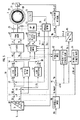
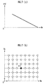
本発明の実施の形態について、図1〜図11を参照して説明する。図1は2重ロータを備えたDCブラシレスモータの構成図、図2は図1に示したDCブラシレスモータの外側ロータと内側ロータの位相差を変更する機構の構成図及び作動説明図、図3及び図4は外側ロータと内側ロータの位相差を変更することによる効果の説明図、図5は電動機の制御装置の制御ブロック図、図6はdq座標系における電圧ベクトル図、図7は誘起電圧定数からロータ位相差を決定するマップ及び誘起電圧定数とq軸電機子のインダクタンスからロータ位相差を決定するマップの説明図、図8は界磁弱め及び界磁強めの効果の説明図、図9は電動機の相電圧を目標電圧円に近づける処理のフローチャート、図10は誘起電圧定数からロータ位相差を決定するマップの説明図、図11はアクチュエータによりロータ位相差を変更する処理のフローチャートである。 Embodiments of the present invention will be described with reference to FIGS. FIG. 1 is a configuration diagram of a DC brushless motor having a double rotor, FIG. 2 is a configuration diagram and an operation explanatory diagram of a mechanism for changing a phase difference between an outer rotor and an inner rotor of the DC brushless motor shown in FIG. And FIG. 4 is an explanatory diagram of the effect of changing the phase difference between the outer rotor and the inner rotor, FIG. 5 is a control block diagram of the motor control device, FIG. 6 is a voltage vector diagram in the dq coordinate system, and FIG. FIG. 8 is an explanatory diagram of a map for determining the rotor phase difference from the constant and a map for determining the rotor phase difference from the induced voltage constant and the inductance of the q-axis armature. FIG. 8 is an explanatory diagram of the effects of field weakening and field strengthening. Is a flowchart of a process for bringing the motor phase voltage close to the target voltage circle, FIG. 10 is an explanatory diagram of a map for determining the rotor phase difference from the induced voltage constant, and FIG. It is a flowchart of a process for further.
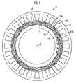
図1を参照して、本実施の形態における電動機1は、永久磁石11a,11bの界磁が周方向に沿って等間隔に配設された内側ロータ11(本発明の第2ロータに相当する)と、永久磁石12a,12bの界磁が周方向に沿って等間隔に配設された外側ロータ12(本発明の第1ロータに相当する)と、内側ロータ11及び外側ロータ12に対する回転磁界を発生させるための電機子10aを有するステータ10とを備えたDCブラシレスモータである。電動機1は、例えばハイブリッド車両や電動車両の駆動源として使用され、ハイブリッド車両に搭載されたときは、電動機及び発電機として動作する。
Referring to FIG. 1, an electric motor 1 according to the present embodiment includes an inner rotor 11 (corresponding to a second rotor of the present invention) in which the fields of
内側ロータ11と外側ロータ12は、共に回転軸が電動機1の回転軸2と同軸となるように同心円状に配置されている。そして、内側ロータ11においては、N極を回転軸2側とする永久磁石11aとS極を回転軸2側とする永久磁石11bが交互に配設されている。同様に、外側ロータ12においても、N極を回転軸2側とする永久磁石12aとS極を回転軸2側とする永久磁石12bが交互に配設されている。
The
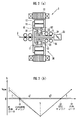
次に、電動機1は、外側ロータ12と内側ロータ11の位相差であるロータ位相差を変更するために、図2(a)に示した遊星歯車機構30を備えている。図2(a)を参照して、遊星歯車機構30は、内側ロータ11の内周側の中空部に配置されたシングルピニオン型の遊星歯車機構であり、外側ロータ12と同軸且つ一体に形成された第1リングギアR1、内側ロータ11と同軸且つ一体に形成された第2リングギアR2、第1リングギアR1と噛合する第1プラネタリギア31、第2リングギアR2に噛合する第2プラネタリギア32、第1プラネタリギア31及び第2プラネタリギア32と噛合するアイドルギアであるサンギアS、第1プラネタリギア31を回転自在に支持すると共に回転軸2に回転可能に軸支された第1プラネタリキャリアC1、及び第2プラネタリギア32を回転自在に支持すると共にステータ10に固定された第2プラネタリキャリアC2を備えている。
Next, the electric motor 1 includes the
遊星歯車機構30において、第1リングギアR1と第2リングギアR2は略同等のギア形状とされ、第1プラネタリギア31と第2プラネタリギア32も略同等のギア形状とされている。また、サンギアSの回転軸33は電動機1の回転軸2と同軸に配置されると共に、軸受け34により回転可能に軸支されている。そして、これにより、第1プラネタリギア31と第2プラネタリギア32がサンギアSと噛合し、外側ロータ12と内側ロータ11が同期して回転するように構成されている。
In the
さらに、第1プラネタリキャリアC1の回転軸35は、電動機1の回転軸2と同軸に配置されると共にアクチュエータ25に接続されており、第2プラネタリキャリアC2はステータ10に固定されている。
Further, the
アクチュエータ25は、外部から入力される制御信号に応じて、油圧により第1プラネタリキャリアC1を正転方向又は逆転方向に回転させ、或いは回転軸2回りの第1プラネタリキャリアC1の回転を規制する。そして、アクチュエータ25によって第1プラネタリキャリアC1が回転すると、外側ロータ12と内側ロータ11間の相対的な位置関係(位相差)が変化する。なお、遊星歯車機構30とアクチュエータ25により、本発明のロータ位相差変更手段が構成される。また、油圧ではなく電動により第1プラネタリキャリアC1を回転させるアクチュエータを用いてもよい。
The
図2(b)は、遊星歯車機構30における第1リングギアR1と、第1プラネタリキャリアC1と、サンギアSと、第2プラネタリキャリアC2と、第2リングギアR2の回転速度の関係を示した図であり、縦軸が各ギアの回転速度Vrに設定されている。
FIG. 2B shows the relationship among the rotational speeds of the first ring gear R1, the first planetary carrier C1, the sun gear S, the second planetary carrier C2, and the second ring gear R2 in the
図2(b)において、ステータ10に固定された第2プラネタリキャリアC2の速度はゼロである。そのため、第2リングギアR2及び内側ロータ11は、例えば逆転方向(Vr<0)に回動するサンギアSに対して、第2リングギアR2に対するサンギアSのギア比g2に応じた速度で正転方向(Vr>0)に回転することになる。
In FIG. 2B, the speed of the second planetary carrier C2 fixed to the
ここで、アクチュエータ25が非作動状態(アクチュエータ25による第1プラネタリキャリアC1の回動がなされていない状態)にあるときは、第1プラネタリキャリアC1の回転速度はゼロである。そのため、第1リングギアR1及び外側ロータ12は、回転するサンギヤSに対して、第1リングギアR1に対するサンギアSのギア比g1に応じた速度で逆方向に回転する。そして、ギヤ比g1とギヤ比g2は略同等(g1≒g2)に設定されているので、内側ロータ11と外側ロータ12は同期して回転し、内側ロータ11と外側ロータ12間の位相差が一定に維持される。
Here, when the
一方、アクチュエータ25が作動状態(アクチュエータ25により第1プラネタリキャリアC1が回動している状態)にあるときは、第1リングギアR1及び外側ロータ12は、回転するサンギアSに対して、第1リングギアR1に対するサンギアSのギア比g1に応じた速度に対して、第1プラネタリキャリアC1の回動分だけ増速又は減速されて、逆方向に回転する。そして、これにより、外側ロータ12と内側ロータ11の位相差が変化する。
On the other hand, when the
また、アクチュエータ25は、第1リングギアR1に対するサンギアSのギア比g1と電動機1の極対数Pに対して、少なくとも、機械角度β(度)=(180/P)×g1/(1+g1)だけ、第1プラネタリキャリアC1を正転方向又は逆転方向に回動可能に構成されている。
The
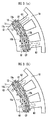
そのため、外側ロータ12と内側ロータ11の位相差は、少なくとも電気角で180度の範囲で進角側又は遅角側に変更することができ、電動機1の状態は、外側ロータ12の永久磁石12a,12bと内側ロータ11の永久磁石11a,11bが同極同士を対向して配置された界磁弱め状態と、外側ロータ12の永久磁石12a,12bと内側ロータ11の永久磁石11a,11bが異極同士を対向して配置された界磁強め状態との間で、適宜設定可能である。
Therefore, the phase difference between the
図3(a)は界磁強め状態を示しており、外側ロータ12の永久磁石12a,12bの磁束Q2と内側ロータ11の永久磁石11a,11bの磁束Q1の向きが同一であるため、合成された磁束Q3が大きくなる。一方、図3(b)は界磁弱め状態を示しており、外側ロータ12の永久磁石12a,12bの磁束Q2と内側ロータ11の永久磁石11a,11bの磁束Q1の向きが逆であるため、合成された磁束Q3が小さくなる。
FIG. 3 (a) shows a field strengthening state. Since the directions of the magnetic flux Q2 of the
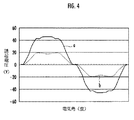
図4は、図3(a)の状態と図3(b)の状態において、電動機1を所定回転数で作動させた場合にステータ10の電機子に生じる誘起電圧を比較したグラフであり、縦軸が誘起電圧(V)に設定され、横軸が電気角(度)に設定されている。図中aが図3(a)の状態(界磁強め状態)であり、bが図3(b)の状態(界磁弱め状態)である。図4から、外側ロータ12と内側ロータ11の位相差を変更することで、生じる誘起電圧のレベルが大幅に変化していることがわかる。
FIG. 4 is a graph comparing the induced voltages generated in the armature of the
そして、このように、外側ロータ12と内側ロータ11の位相差を変更して、界磁の磁束を増減させることにより、電動機1の誘起電圧定数Keを変化させることができる。これにより、誘起電圧定数Keが一定である場合に比べて、電動機1の出力及び回転数に対する運転可能領域を拡大することができる。また、電動機の制御として一般的なdq座標変換により、d軸(界磁軸)側の電機子に通電して界磁弱め制御を行う場合に比べて、電動機1の銅損が減少するため、電動機1の運転効率を高めることができる。
Thus, the induced voltage constant Ke of the electric motor 1 can be changed by changing the phase difference between the
次に、図5〜図11を参照して、本発明の電動機の制御装置について説明する。図5に示した電動機の制御装置(以下、単に制御装置という)は、電動機1を界磁方向をd軸としてd軸と直交する方向をq軸とした2相直流の回転座標系による等価回路に変換して扱い、外部から与えられるトルク指令値Tr_cに応じたトルクが電動機1から出力されるように、電動機1に対する通電量を制御するものである。 Next, the motor control device of the present invention will be described with reference to FIGS. The motor control device (hereinafter simply referred to as control device) shown in FIG. 5 is an equivalent circuit based on a two-phase DC rotating coordinate system in which the motor 1 has a field direction as a d-axis and a direction orthogonal to the d-axis as a q-axis. The amount of current supplied to the motor 1 is controlled so that torque according to the torque command value Tr_c given from the outside is output from the motor 1.
制御装置はCPU、メモリ等により構成される電子ユニットであり、トルク指令値Tr_cと電動機1の外側ロータ12と内側ロータ11の位相差(ロータ位相差)の推定値θd_eとに基づいて、d軸側の電機子(以下、d軸電機子という)に流れる電流(以下、d軸電流という)の指令値Id_cとq軸側の電機子(以下、q軸電機子という)に流れる電流(以下、q軸電流という)の指令値Iq_cとを決定する電流指令値決定部60(本発明の電流指令値決定手段に相当する)、電流センサ70,71(本発明の電流検出手段に相当する)により検出されてバンドパスフィルタ72により不要成分が除去された電流検出信号と、レゾルバ73(本発明のロータ位置検出手段に相当する)により検出された外側ロータ12のロータ角度θrとに基づいて、3相/dq変換によりd軸電流の検出値Id_sとq軸電流の検出値Iq_sとを算出する3相/dq変換部75、d軸電流の指令値Id_cと検出値Id_sの偏差ΔId及びq軸電流の指令値Iq_cと検出値Iq_sの偏差ΔIqを減少させるように、d軸電機子の端子間電圧(以下、d軸電圧という)の指令値Vd_cとq軸電機子の端子間電圧(以下、q軸電圧という)の指令値Vq_cとを決定する通電制御部50(本発明の通電制御手段に相当する)、d軸電圧の指令値Vd_cとq軸電圧の指令値Vq_cを大きさV1と角度θの成分に変換するrθ変換部61、及び該大きさV1と角度θの成分をPWM制御により3相(U,V,W)の交流電圧に変換するPWM演算部62(本発明のインバータ回路の機能を含む)を備えている。
The control device is an electronic unit including a CPU, a memory, and the like, and is based on the torque command value Tr_c and the estimated value θd_e of the phase difference (rotor phase difference) between the
さらに、制御装置は、d軸電圧の指令値Vd_c及びq軸電圧の指令値Vq_cとd軸電流の検出値Id_s及びq軸電流の検出値Iq_sと電動機1の角速度の検出値ω_s(図示しない角速度検出手段により検出される)とに基づいて、電動機1の誘起電圧定数Keとq軸電機子のインダクタンスLqとを算出する定数算出部63(本発明の誘起電圧定数算出手段の機能を含む)、誘起電圧定数Keとq軸電機子のインダクタンスLqとに基づいてロータ位相差の推定値θd_eを求めるロータ位相差推定部64(本発明のロータ位相差推定手段に相当する)、PWM演算部62に直流電力を供給する直流電源(図示しない)の出力電圧Vdcから後述する目標電圧円の半径Vp_targetを算出する目標電圧円算出部90、d軸電圧の指令値Vd_cとq軸電圧の指令値Vq_cから後述する実電圧円の半径Vpを算出する実電圧円算出部92、Vp_targetとVpとの偏差ΔVpに基づいて誘起電圧定数の指令値Ke_cを決定する誘起電圧定数指令値決定部93、誘起電圧定数の指定値Ke_cとΔVpとに基づいてd軸電流の指令値Id_cの補正値ΔId_volを算出する界磁弱め電流補正値算出部94、誘起電圧定数の指令値Ke_cに対応したロータ位相差θd_c1を取得するロータ位相差取得部95、該θd_c1とロータ位相差の推定値θd_eとの偏差Δθdに基づいてロータ位相差の指令値θd_c2を決定するロータ位相差指令値決定部97を備えている。
Further, the control device performs a command value Vd_c for the d-axis voltage, a command value Vq_c for the q-axis voltage, a detected value Id_s for the d-axis current, a detected value Iq_s for the q-axis current, and a detected value ω_s for the angular velocity of the electric motor 1 A constant calculating unit 63 (including the function of the induced voltage constant calculating means of the present invention) that calculates the induced voltage constant Ke of the electric motor 1 and the inductance Lq of the q-axis armature based on A rotor phase difference estimator 64 (corresponding to the rotor phase difference estimator of the present invention) for obtaining an estimated value θd_e of the rotor phase difference based on the induced voltage constant Ke and the inductance Lq of the q-axis armature, A target voltage circle calculation unit 90 that calculates a radius Vp_target of a target voltage circle, which will be described later, from an output voltage Vdc of a DC power supply (not shown) that supplies DC power, from a d-axis voltage command value Vd_c and a q-axis voltage command value Vq_c rear An actual voltage circle calculating unit 92 for calculating the radius Vp of the actual voltage circle to be generated, an induced voltage constant command value determining unit 93 for determining the command value Ke_c of the induced voltage constant based on the deviation ΔVp between Vp_target and Vp, A field weakening current correction value calculation unit 94 that calculates a correction value ΔId_vol of the command value Id_c of the d-axis current based on the specified value Ke_c and ΔVp, and obtains a rotor phase difference θd_c1 corresponding to the command value Ke_c of the induced voltage constant. The rotor phase
なお、界磁弱め電流補正値算出部94と、d軸電流の指令値Id_cに界磁弱め電流の補正値ΔId_volを加算する加算器51とにより、本発明の界磁弱め電流補正手段が構成される。また、目標電圧円算出部90、減算器91、実電圧円算出部92、誘起電圧定数指令値決定部93、ロータ位相差取得部95、減算器96、及びロータ位相差指令値決定部97により、本発明のロータ位相差指令値決定手段が構成される。
The field weakening current correction means 94 of the present invention is configured by the field weakening current correction
また、通電制御部50は、d軸電流の指令値Id_cに補正値ΔId_volを加算する加算器51、該補正値ΔId_volが加算されたd軸電流の指令値Id_caとd軸電流の検出値Id_sとの偏差ΔIdを算出する減算器52、該偏差ΔIdを生じさせるためのd軸偏差電圧ΔVdを算出するd軸電流制御部53、d軸電流の指令値Id_cとq軸電流の指令値Iq_cとに基づいて、d軸とq軸間で干渉し合う速度起電力の影響を打ち消すための成分(非干渉成分)を算出する非干渉制御部56、d軸偏差電圧ΔVdから非干渉制御部56により算出された非干渉成分を減じる減算器54、q軸電流の指令値Iq_cと検出値Iq_sとの偏差ΔIqを算出する減算器55、該偏差ΔIqを生じさせるためのq軸偏差電圧ΔVqを算出するq軸電流制御部57、及びq軸偏差電圧ΔVqに非干渉成分を加える加算器58を備えている。
Further, the
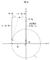
次に、図6はdq座標系における電流と電圧の関係を示したものであり、縦軸がq軸(トルク軸)に設定され、横軸がd軸(界磁軸)に設定されている。図中Cは目標電圧円算出部90によってその半径Vp_targetが算出される目標電圧円である。Vp_targetは例えばVdc×0.5に設定され、或いは正弦波変調に対応したVdc/61/2に設定される。 Next, FIG. 6 shows the relationship between current and voltage in the dq coordinate system. The vertical axis is set to the q axis (torque axis), and the horizontal axis is set to the d axis (field axis). . In the figure, C is a target voltage circle whose radius Vp_target is calculated by the target voltage circle calculator 90. Vp_target is set to Vdc × 0.5, for example, or Vdc / 6 1/2 corresponding to sinusoidal modulation.
そして、制御装置は、d軸電機子の端子間電圧Vdとq軸電機子の端子間電圧Vqの合成ベクトルV(その大きさが実電圧円の半径となる)が、目標電圧円Cの円周上をトレースするように、ロータ位相差とd軸電流及びq軸電流を制御する。なお、図中Eは電動機1の回転によりq軸電機子に生じる逆起電力、ωは電動機1の角速度、Rはd軸電機子及びq軸電機子の抵抗、Lqはq軸電機子のインダクタンス、Ldはd軸電機子のインダクタンス、Vdはd軸電圧、Vqはq軸電圧、Idはd軸電流、Iqはq軸電流である。 Then, the control device determines that the combined vector V of the terminal voltage Vd of the d-axis armature and the terminal voltage Vq of the q-axis armature (the magnitude of which is the radius of the actual voltage circle) is a circle of the target voltage circle C. The rotor phase difference, d-axis current, and q-axis current are controlled so as to trace the circumference. In the figure, E is a counter electromotive force generated in the q-axis armature by the rotation of the motor 1, ω is the angular velocity of the motor 1, R is the resistance of the d-axis armature and the q-axis armature, and Lq is the inductance of the q-axis armature. , Ld is the inductance of the d-axis armature, Vd is the d-axis voltage, Vq is the q-axis voltage, Id is the d-axis current, and Iq is the q-axis current.
ここで、図6のq軸側の成分について、以下の式(1)の関係が成立するため、以下の式(2)から電動機1の誘起電圧定数Keを算出することができる。 Here, with respect to the component on the q-axis side in FIG. 6, the relationship of the following equation (1) is established, and therefore the induced voltage constant Ke of the electric motor 1 can be calculated from the following equation (2).
![]()
![]()
但し、Ke:誘起電圧定数、ω:電動機の角速度、R:q軸電機子及びd軸電機子の抵抗、Iq:q軸電流、Vq:q軸電機子の端子間電圧、Ld:d軸電機子のインダクタンス、Id:d軸電流。 Where Ke: induced voltage constant, ω: angular velocity of motor, R: resistance of q-axis armature and d-axis armature, Iq: q-axis current, Vq: voltage between terminals of q-axis armature, Ld: d-axis electric machine Child inductance, Id: d-axis current.

また、図6のd軸側の成分について、以下の式(3)の関係が成立するため、以下の式(4)からq軸電機子のインダクタンスLqを算出することができる。 Moreover, since the relationship of the following formula | equation (3) is materialized about the component of the d-axis side of FIG. 6, the inductance Lq of a q-axis armature is computable from the following formula | equation (4).
![]()
![]()
そこで、定数算出部63は、q軸指令電圧Vq_c、電機子1の角速度の検出値ω_s、d軸電流の検出値Id_s、及びq軸電流の検出値Iq_sを、上記式(2)のVq、ω、Id、及びIqにそれぞれ代入して、誘起電圧定数Keを算出する。また、定数検出部63は、d軸電流の検出値Id、d軸電圧の指令値Vd_c、電機子1の角速度の検出値ω_s、及びq軸電流の検出値Iqを、上記式(4)のId、Vd、ω、及びIqにそれぞれ代入して、q軸電機子のインダクタンスLqを算出する。
Therefore, the
なお、上記式(2),式(4)におけるd軸電機子及びq軸電機子の抵抗Rは、予め設定した固定値である。また、上記式(2)におけるd軸電機子のインダクタンスLdは、予め設定した固定値としてもよいが、ロータ位相差が大きくなるほどd軸電機子のインダクタンスLdが小さくなるので、ロータ位相差の指令値θd_cが大きいほどインダクタンスLdが小さくなるようにした推定値を用いてもよい。 In addition, the resistance R of the d-axis armature and the q-axis armature in the above formulas (2) and (4) is a preset fixed value. Further, the inductance Ld of the d-axis armature in the above formula (2) may be a fixed value set in advance. However, since the inductance Ld of the d-axis armature decreases as the rotor phase difference increases, the rotor phase difference command An estimated value in which the inductance Ld is decreased as the value θd_c is increased may be used.
次に、ロータ位相差推定部64は、定数検出部63により算出された誘起電圧定数Keとq軸電機子のインダクタンスLqとに基づいて、ロータ位相差の推定値θd_eを求める。ここで、ロータ位相差が変化すると、それに応じて電動機1の誘起電圧定数Keとq軸電機子のインダクタンスLqが変化する。
Next, the rotor phase
そこで、ロータ位相差推定部64は、図7(b)に示したKe,Lq/θdの対応マップに、定数検出部63により算出された誘起電圧定数Keとq軸電機子のインダクタンスLqとを適用して対応する位相差θdを取得し、該位相差θdを外側ロータ12と内側ロータ11の位相差の推定値θd_eとする。
Therefore, the rotor phase
なお、Ke,Lq/θdの対応マップは、実験データやコンピュータシミュレーションに基づいて作成され、予めメモリ(図示しない)に記憶されている。また、図7(a)に示したKe/θdの対応マップに、定数算出部63により算出された誘起電圧定数Keを適用して、θd_eを求めることもできるが、誘起電圧定数Keに加えてq軸電機子のインダクタンスLqを用いてロータ位相差の推定値θd_eを求めることで、ロータ位相差の推定精度を高めることができる。
The correspondence map of Ke and Lq / θd is created based on experimental data and computer simulation, and is stored in advance in a memory (not shown). In addition, the induced voltage constant Ke calculated by the constant calculating
そして、電流指令値決定部60は、予めメモリに記憶されたTr,θd/Id,Iqの対応マップに、トルク指令値Tr_cと、ロータ位相差の推定値θd_eを適用して、対応するId,Iqを取得し、該取得したId,Iqをそれぞれd軸電流の指令値Id_c及びq軸電流の指令値として決定する。このように、ロータ位相差の推定値θd_eを用いることで、実際の電動機1の界磁の磁束の変化を反映したd軸電流の指令値Id_c及びq軸電流の指令値Iq_cを決定することができる。そのため、トルク指令値Tr_cに対して電動機1の出力トルクを精度良く制御することができる。
Then, the current command
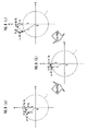
次に、図8を参照して、d軸電機子の端子間電圧とq軸電圧の端子間電圧の合成ベクトルVが目標電圧円Cの周上をトレースするように、ロータ位相差を変更することによる効果について説明する。 Next, referring to FIG. 8, the rotor phase difference is changed so that the combined vector V of the terminal voltage of the d-axis armature and the terminal voltage of the q-axis voltage traces the circumference of the target voltage circle C. The effect by this will be described.
図8(a)は、合成ベクトルVが目標電圧円Cの内側にある場合であり、この場合は、ロータ位相差を界磁の磁束を増加させる方向(界磁を強める方向)に変更する。そして、これにより、電動機1の誘起電圧定数Keが増大し、誘起電圧定数Keが増大した分、q軸電機子で発生する逆起電力Eが大きくなる。その結果、図8(b)に示したように、合成ベクトルVが目標電圧円Cの円周上に移動すると、q軸電流Iqとd軸電流Idが減少する。そのため、電動機1で生じる銅損を減少させることができる。 FIG. 8A shows a case where the combined vector V is inside the target voltage circle C. In this case, the rotor phase difference is changed to a direction in which the field magnetic flux is increased (the direction in which the field is strengthened). As a result, the induced voltage constant Ke of the electric motor 1 increases, and the back electromotive force E generated by the q-axis armature increases as the induced voltage constant Ke increases. As a result, as shown in FIG. 8B, when the combined vector V moves on the circumference of the target voltage circle C, the q-axis current Iq and the d-axis current Id decrease. Therefore, the copper loss generated in the electric motor 1 can be reduced.
また、図8(c)は、合成ベクトルVが目標電圧円Cの外側にある場合であり、この場合は、ロータ位相差を界磁の磁束を減少させる方向(界磁を弱める方向)に変更する。そして、これにより、電動機1の誘起電圧定数Keが減少し、誘起電圧定数Keが減少した分、q軸電機子で発生する逆起電力Eが小さくなる。その結果、図8(b)に示したように、合成ベクトルVが目標電圧円Cの円周上に移動すると、PWM演算部62から電動機1への通電が可能となり、電動機1の動作範囲を拡大することができる。
FIG. 8C shows a case where the combined vector V is outside the target voltage circle C. In this case, the rotor phase difference is changed to a direction in which the magnetic flux of the field is reduced (a direction in which the field is weakened). To do. As a result, the induced voltage constant Ke of the electric motor 1 is reduced, and the back electromotive force E generated in the q-axis armature is reduced by the amount that the induced voltage constant Ke is reduced. As a result, as shown in FIG. 8B, when the combined vector V moves on the circumference of the target voltage circle C, the motor 1 can be energized from the
そして、このように、ロータ位相差を変更して界磁弱め制御を行った場合、d軸電流を増加させて界磁弱め制御を行う場合に比べて、電動機1で生じる銅損を減少させることができる。また、合成ベクトルVが目標電圧円Cの円周上をトレースするように、ロータ位相差を変更することによって、PWM演算部62におけるスイッチングによる電力損失を低減することができる。
Thus, when the field weakening control is performed by changing the rotor phase difference, the copper loss generated in the electric motor 1 is reduced compared to the case where the field weakening control is performed by increasing the d-axis current. Can do. Further, by changing the rotor phase difference so that the combined vector V traces on the circumference of the target voltage circle C, the power loss due to switching in the
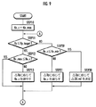
次に、図9に示したフローチャートに従って、制御装置によるロータ位相差及び界磁弱め電流の制御処理について説明する。図9のSTEP10〜STEP13及びSTEP20〜STEP21は誘起電圧定数指令値決定部93による処理であり、STEP30は界磁弱め電流補正値算出部94による処理である。
Next, the control process of the rotor phase difference and the field weakening current by the control device will be described according to the flowchart shown in FIG. In FIG. 9,
誘起電圧定数指令値決定部93は、STEP10で誘起電圧定数の指令値Ke_cの初期値を、ロータ位相差の変更により設定可能な誘起電圧定数の最大値であるKe_max(本実施の形態ではロータ位相差が0度の状態)とする。なお、誘起電圧定数の指令値Ke_cは、ロータ位相差の変更により設定可能な誘起電圧定数の最小値であるKe_min(本実施の形態ではロータ位相差が180度の状態)〜Ke_maxの範囲内で任意に設定すればよい。
The induced voltage constant command
そして、次のSTEP11で、誘起電圧定数指令値決定部93は、実電圧円算出部92により算出されたd軸電圧の指令値Vd_cとq軸電圧の指令値Vq_cの合成ベクトルVの大きさVp(=√(Vd_c2+Vq_c2)、本発明の電動機の各相の電機子の端子間電圧の合成ベクトルの大きさに相当する)が、目標電圧円算出部90により算出された目標電圧円Cの半径Vp_target以下であるか否かを判断する。
Then, in the
そして、VpがVp_target以下であるときはSTEP12に進み、誘起電圧定数指令値決定部93は、誘起電圧定数の指令値Ke_cがKe_max以上であるか否かを判断する。誘起電圧定数の指令値Ke_cがKe_maxよりも小さいときはSTEP13に進み、誘起電圧定数指令値決定部93は、減算器91で算出されたVp_targetとVpとの偏差ΔVpにPI(比例積分)処理を行って、増加した新たな誘起電圧定数の指令値Ke_cを決定する。一方、誘起電圧定数の指令値Ke_cがKe_max以上であるときは、これ以上誘起電圧定数を増加させることができないためSTEP14に分岐し、誘起電圧定数指令値決定部93は、STEP13の処理を行わない。
When Vp is equal to or less than Vp_target, the process proceeds to STEP12, and the induced voltage constant command
また、STEP11でVpがVp_targetよりも大きかったときにはSTEP20に分岐し、誘起電圧定数指令値決定部93は、誘起電圧定数の指令値Ke_cがKe_min以下であるか否かを判断する。そして、誘起電圧定数の指令値Ke_cがKeよりも大きいときはSTEP21に進み、誘起電圧定数指令値決定部93は、減算器91で算出されたVp_targetとVpとの偏差ΔVpにPI(比例積分)処理を行って、減少した新たな誘起電圧定数の指令値Ke_cを決定する。
If Vp is larger than Vp_target in
一方、誘起電圧定数の指令値Ke_cがKe_min以下であるときには、これ以上誘起電圧定数を減少させることができない。そこで、この場合はSTEP30に分岐し、界磁弱め電流補正値算出部94は、誘起電圧定数の指令値Ke_cの変更による界磁弱めの効果に加えて、d軸電流の増加による界磁弱めの効果を生じさせるための補正値ΔId_volを、減算器91で算出されたVp_targetとVpとの偏差ΔVpにPI(比例積分)処理を行って算出し、STEP11に進む。そして、誘起電圧定数指令値決定部93と界磁弱め電流補正値算出部94は、STEP11〜STEP13、STEP20〜STEP21、STEP30の処理を繰り返し実行する。
On the other hand, when the command value Ke_c of the induced voltage constant is equal to or less than Ke_min, the induced voltage constant cannot be further reduced. Therefore, in this case, the process branches to STEP 30, and the field weakening current correction
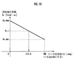
次に、図5を参照して、誘起電圧定数指令値決定部93により決定された誘起電圧定数の指令値Ke_cはロータ位相差取得部95に出力される。そして、ロータ位相差取得部95は、図10に示したKe/θdマップに誘起電圧定数の指令値Ke_cを適用して、Ke_cに対応するロータ位相差θd_c1を取得する。
Next, referring to FIG. 5, the induced voltage constant command value Ke_c determined by the induced voltage constant command
また、減算器96により算出されたθd_c1とロータ位相差推定部64によるロータ位相差の推定値θd_eとの偏差Δθdが、ロータ位相差指令値決定部97に入力され、ロータ位相差指令値決定部97は、ΔθdにPI(比例積分)処理を施してロータ位相差の指令値θd_c2を決定する。
Further, the deviation Δθd between θd_c1 calculated by the
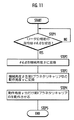
そして、アクチュエータ25は、図11に示した処理を実行して、ロータ位相差を変更する。すなわち、アクチュエータ25は、図11のSTEP1でロータ位相差指令値決定部97からロータ位相差の指令値θd_c2を受信すると、STEP2でθd_c2を機械角度βに変換する。そして、続くSTEP3で、アクチュエータ25は機械角度βを第1プラネタリキャリアC1の動作角度γに変換し、STEP4で該動作角度γ分だけ、第1プラネタリキャリアを回動させる。これにより、ロータ位相差の指令値θd_c2に応じた角度分だけロータ位相差が変更されて電動機1の界磁の磁束が変化し、界磁の強め/弱めの効果が生じる。
Then, the
なお、本実施の形態においては、図9のSTEP11〜STEP13の処理により、ロータ位相差の変更により誘起電圧定数を増大させて相電圧ベクトルの大きさVpを目標電圧円の半径Vp_targetに近づける処理と、STEP20〜STEP21及びSTEP30の処理により、ロータ位相差の変更により誘起電圧定数を減少させて相電圧ベクトルの大記載Vpを目標電圧円の半径Vp_targetに近づける処理とを行ったが、いずれか一方の処理のみを行う場合にも、本発明の効果を得ることができる。
In the present embodiment, the processing in
また、誘起電圧定数の指令値を変更して界磁の磁束を増減する構成の他に、d軸電圧の指令値Vd_cとq軸電圧の指令値Vq_cの合成ベクトルの大きさVpと目標電圧円の半径Vp_targetとの偏差ΔVpに応じて、直接的にロータ位相差の指令値θd_cを変更して、界磁の磁束を増減する構成としてもよい。 In addition to the configuration in which the induced voltage constant command value is changed to increase or decrease the magnetic flux of the field, the magnitude Vp of the combined vector of the command value Vd_c of the d-axis voltage and the command value Vq_c of the q-axis voltage and the target voltage circle It is also possible to directly change the rotor phase difference command value θd_c in accordance with the deviation ΔVp from the radius Vp_target to increase or decrease the field magnetic flux.
また、図9のSTEP20及びSTEP30の処理により、誘起電圧定数の変更では相電圧Vpを目標電圧円の半径Vp_targetまで減少させることができない場合に、d軸電流を増加させて界磁を弱める処理を行ったが、かかる処理を行わない場合であっても、本発明の効果を得ることができる。
Further, when the phase voltage Vp cannot be reduced to the radius Vp_target of the target voltage circle by changing the induced voltage constant by the processing of
また、本実施の形態においては、図9のSTEP11で、d軸電圧の指令値Vd_cとq軸電圧の指令値Vq_cの合成ベクトルVの大きさVpと、目標電圧円の半径Vp_targetとを比較したが、電動機1の電機子の端子間電圧を検出して各相の端子間電圧の合成ベクトルの大きさを算出し、その算出値(本発明の電動機の各相の電機子の端子間電圧の合成ベクトルの大きさに相当する)と目標電圧円の半径Vp_targetとを比較するようにしてもよい。
In the present embodiment, the magnitude Vp of the combined vector V of the d-axis voltage command value Vd_c and the q-axis voltage command value Vq_c is compared with the radius Vp_target of the target voltage circle in
また、本実施の形態では、電動機をd軸及びq軸からなる2相直流の回転座標系による等価回路に変換して扱う電動機の制御装置を示したが、α軸及びβ軸からなる2相交流の固定座標系による等価回路に変換して扱う電動機の制御装置や、等価回路への変換を行わずに3相交流のまま扱う電動機の制御装置においても、本発明の適用が可能である。 Further, in the present embodiment, the motor control device is shown which converts the motor into an equivalent circuit using a two-phase DC rotating coordinate system consisting of d-axis and q-axis, but the two-phase consisting of α-axis and β-axis is shown. The present invention can also be applied to an electric motor control device that is handled by converting it into an equivalent circuit using an AC fixed coordinate system, and an electric motor control device that is handled as a three-phase alternating current without conversion to an equivalent circuit.
1…電動機、2…電動機の回転軸、10…ステータ、11…内側ロータ、11a,11b…永久磁石、12…外側ロータ、12a,12b…永久磁石、25…アクチュエータ、30…遊星歯車機構、C1…第1プラネタリキャリア、C2…第2プラネタリキャリア、R1…第1リングギア、R2…第2リングギア、S…サンギア、31…第1プラネタリギア、32…第2プラネタリギア、33…サンギアの回転軸、34…軸受け、35…第1プラネタリキャリアの回転軸、50…通電制御部、60…電流指令値決定部、63…定数算出部、64…ロータ位相差推定部、90…目標電圧円算出部、92…実電圧円算出部、93…誘起電圧定数指令値決定部、94…界磁弱め電流補正値算出部、95…ロータ位相差取得部、97…ロータ位相差指令値決定部
DESCRIPTION OF SYMBOLS 1 ... Electric motor, 2 ... Motor rotating shaft, 10 ... Stator, 11 ... Inner rotor, 11a, 11b ... Permanent magnet, 12 ... Outer rotor, 12a, 12b ... Permanent magnet, 25 ... Actuator, 30 ... Planetary gear mechanism, C1 ... first planetary carrier, C2 ... second planetary carrier, R1 ... first ring gear, R2 ... second ring gear, S ... sun gear, 31 ... first planetary gear, 32 ... second planetary gear, 33 ... sun
Claims (4)
直流電源から供給される直流電力を前記電動機の電機子に供給する多相交流電力に変換するインバータ回路と、
前記電動機の各相の電機子の端子間電圧の合成ベクトルの大きさが、前記直流電源の出力電圧以下に設定された所定電圧よりも小さいときに、前記電動機の界磁の磁束が増加する方向に前記ロータ位相差の指令値を決定するロータ位相差指令値決定手段と、
前記ロータ位相差の指令値に応じて、前記ロータ位相差を変更するロータ位相差変更手段と、
前記第1ロータの位置を検出するロータ位置検出手段と、
前記第1ロータの位置に基づいて、前記電動機を界磁の磁束方向であるd軸と該d軸に直交するq軸からなる2相直流の回転座標系による等価回路に変換して扱い、該等価回路における各軸の電機子の通電量を制御することにより、前記電動機の通電制御を行う通電制御手段と、
前記電動機の電機子に流れる電流を検出する電流検出手段と、
前記電動機の角速度を検出する角速度検出手段と、
前記電動機の電機子の端子間電圧及び該電機子に流れる電流の前記等価回路における変換値と、前記電動機の角速度とに基づいて、前記電動機の誘起電圧定数を算出する誘起電圧定数算出手段と、
該誘起電圧定数算出手段により算出された前記電動機の誘起電圧定数と、出力トルクの指令値とに基づいて、前記通電制御手段による前記電動機の通電制御における前記等価回路のd軸側の電機子の通電量の指令値及びq軸側の電機子の通電量の指令値を決定する電流指令値決定手段とを備えたことを特徴とする電動機の制御装置。 The operation of a permanent magnet field-type rotary motor in which a first rotor and a second rotor having a plurality of fields by permanent magnets are arranged concentrically around the rotation shaft, the first rotor, the second rotor, A control device for an electric motor that performs field control by changing a rotor phase difference that is a phase difference of
An inverter circuit for converting DC power supplied from a DC power source into multiphase AC power supplied to the armature of the motor;
The direction in which the magnetic flux of the field of the electric motor increases when the magnitude of the combined vector of the voltage between the terminals of the armature of each phase of the electric motor is smaller than a predetermined voltage set below the output voltage of the DC power supply Rotor phase difference command value determining means for determining the rotor phase difference command value;
Rotor phase difference changing means for changing the rotor phase difference according to a command value of the rotor phase difference ;
Rotor position detecting means for detecting the position of the first rotor;
Based on the position of the first rotor, the electric motor is converted into an equivalent circuit based on a two-phase DC rotating coordinate system including a d-axis that is a magnetic flux direction of the field and a q-axis that is orthogonal to the d-axis, Energization control means for controlling energization of the motor by controlling the energization amount of the armature of each axis in the equivalent circuit;
Current detecting means for detecting a current flowing in the armature of the motor;
Angular velocity detection means for detecting the angular velocity of the electric motor;
An induced voltage constant calculating means for calculating an induced voltage constant of the motor based on a converted value in the equivalent circuit of the voltage between the terminals of the armature of the motor and the current flowing through the armature, and an angular velocity of the motor;
Based on the induced voltage constant of the motor calculated by the induced voltage constant calculating means and the command value of the output torque, the armature on the d-axis side of the equivalent circuit in the energization control of the motor by the energization control means An electric motor control device comprising: a command value for energization amount and a current command value determining means for determining a command value for the energization amount of the armature on the q-axis side .
直流電源から供給される直流電力を前記電動機の電機子に供給する多相交流電力に変換するインバータ回路と、
前記電動機の各相の電機子の端子間電圧の合成ベクトルの大きさが、前記直流電源の出力電圧以下に設定された目標電圧よりも大きいときに、前記電動機の界磁の磁束が減少する方向に前記ロータ位相差の指令値を決定するロータ位相差指令値決定手段と、
前記ロータ位相差の指令値に応じて、前記ロータ位相差を変更するロータ位相差変更手段と、
前記第1ロータの位置を検出するロータ位置検出手段と、
前記第1ロータの位置に基づいて、前記電動機を界磁の磁束方向であるd軸と該d軸に直交するq軸からなる2相直流の回転座標系による等価回路に変換して扱い、該等価回路における各軸の電機子の通電量を制御することにより、前記電動機の通電制御を行う通電制御手段と、
前記電動機の電機子に流れる電流を検出する電流検出手段と、
前記電動機の角速度を検出する角速度検出手段と、
前記電動機の電機子の端子間電圧及び該電機子に流れる電流の前記等価回路における変換値と、前記電動機の角速度とに基づいて、前記電動機の誘起電圧定数を算出する誘起電圧定数算出手段と、
該誘起電圧定数算出手段により算出された前記電動機の誘起電圧定数と、出力トルクの指令値とに基づいて、前記通電制御手段による前記電動機の通電制御における前記等価回路のd軸側の電機子の通電量の指令値及びq軸側の電機子の通電量の指令値を決定する電流指令値決定手段とを備えたことを特徴とする電動機の制御装置。 The operation of a permanent magnet field-type rotary motor in which a first rotor and a second rotor having a plurality of fields by permanent magnets are arranged concentrically around the rotation shaft, the first rotor, the second rotor, A control device for an electric motor that performs field control by changing a rotor phase difference that is a phase difference of
An inverter circuit for converting DC power supplied from a DC power source into multiphase AC power supplied to the armature of the motor;
The direction in which the magnetic flux of the field of the motor decreases when the magnitude of the combined vector of the voltage between the terminals of the armature of each phase of the motor is larger than the target voltage set below the output voltage of the DC power supply Rotor phase difference command value determining means for determining the rotor phase difference command value;
Rotor phase difference changing means for changing the rotor phase difference according to a command value of the rotor phase difference ;
Rotor position detecting means for detecting the position of the first rotor;
Based on the position of the first rotor, the electric motor is converted into an equivalent circuit based on a two-phase DC rotating coordinate system composed of a d-axis that is a magnetic flux direction of the field and a q-axis that is orthogonal to the d-axis, Energization control means for controlling energization of the motor by controlling the energization amount of the armature of each axis in the equivalent circuit;
Current detecting means for detecting a current flowing in the armature of the motor;
Angular velocity detection means for detecting the angular velocity of the electric motor;
An induced voltage constant calculating means for calculating an induced voltage constant of the motor based on a converted value in the equivalent circuit of the voltage between the terminals of the armature of the motor and the current flowing through the armature, and an angular velocity of the motor;
Based on the induced voltage constant of the motor calculated by the induced voltage constant calculating means and the command value of the output torque, the armature on the d-axis side of the equivalent circuit in the energization control of the motor by the energization control means An electric motor control device comprising: a command value for energization amount and a current command value determining means for determining a command value for the energization amount of the armature on the q-axis side .
Priority Applications (3)
| Application Number | Priority Date | Filing Date | Title |
|---|---|---|---|
| JP2006078553A JP4754379B2 (en) | 2006-03-22 | 2006-03-22 | Electric motor control device |
| US11/723,586 US7548038B2 (en) | 2006-03-22 | 2007-03-21 | Controller for motor |
| DE102007013575A DE102007013575B4 (en) | 2006-03-22 | 2007-03-21 | motor control |
Applications Claiming Priority (1)
| Application Number | Priority Date | Filing Date | Title |
|---|---|---|---|
| JP2006078553A JP4754379B2 (en) | 2006-03-22 | 2006-03-22 | Electric motor control device |
Publications (3)
| Publication Number | Publication Date |
|---|---|
| JP2007259550A JP2007259550A (en) | 2007-10-04 |
| JP2007259550A5 JP2007259550A5 (en) | 2008-10-23 |
| JP4754379B2 true JP4754379B2 (en) | 2011-08-24 |
Family
ID=38514808
Family Applications (1)
| Application Number | Title | Priority Date | Filing Date |
|---|---|---|---|
| JP2006078553A Expired - Fee Related JP4754379B2 (en) | 2006-03-22 | 2006-03-22 | Electric motor control device |
Country Status (3)
| Country | Link |
|---|---|
| US (1) | US7548038B2 (en) |
| JP (1) | JP4754379B2 (en) |
| DE (1) | DE102007013575B4 (en) |
Families Citing this family (23)
| Publication number | Priority date | Publication date | Assignee | Title |
|---|---|---|---|---|
| JP4879657B2 (en) * | 2006-05-31 | 2012-02-22 | 本田技研工業株式会社 | Electric motor control device |
| EP2072312A1 (en) * | 2007-12-18 | 2009-06-24 | Nederlandse Organisatie voor toegepast- natuurwetenschappelijk onderzoek TNO | A vehicle drive system and use of an electromechanical converter |
| DE102008062515A1 (en) * | 2007-12-21 | 2009-06-25 | Denso Corporation, Kariya | Device for controlling a torque of a rotary electric machine |
| JP5172418B2 (en) * | 2008-03-28 | 2013-03-27 | 本田技研工業株式会社 | Control device for electric motor system |
| JP5273706B2 (en) * | 2008-04-03 | 2013-08-28 | 本田技研工業株式会社 | Electric motor control device |
| JP5172437B2 (en) * | 2008-04-03 | 2013-03-27 | 本田技研工業株式会社 | Electric motor control device |
| JP5259241B2 (en) * | 2008-04-23 | 2013-08-07 | 株式会社東芝 | Motor controller, motor drive system, washing machine, air conditioner, method of changing the amount of magnetization of a permanent magnet motor |
| US8604735B2 (en) * | 2008-05-16 | 2013-12-10 | Freescale Semiconductor, Inc. | Method and apparatus for control of an AC electric motor with field weakening |
| US7911176B2 (en) * | 2008-07-30 | 2011-03-22 | General Electric Company | Systems and methods involving permanent magnet electric machine rotor position determination |
| JP5526975B2 (en) * | 2009-05-13 | 2014-06-18 | 株式会社安川電機 | Electric motor control device and control method thereof |
| JP5574790B2 (en) * | 2010-04-08 | 2014-08-20 | オムロンオートモーティブエレクトロニクス株式会社 | Motor drive device |
| JP5534935B2 (en) * | 2010-05-20 | 2014-07-02 | 株式会社東芝 | Rotation sensorless control device |
| GB201301259D0 (en) * | 2013-01-24 | 2013-03-06 | Rolls Royce Plc | Method of controlling an ac machine and controller for controlling an ac machine |
| DE102013004954B4 (en) * | 2013-03-22 | 2022-07-07 | Audi Ag | Method for operating a multi-phase electrical machine and corresponding multi-phase electrical machine |
| JP5842852B2 (en) * | 2013-04-02 | 2016-01-13 | トヨタ自動車株式会社 | Rotating electrical machine control system and rotating electrical machine control method |
| JP6003924B2 (en) * | 2014-02-25 | 2016-10-05 | 株式会社安川電機 | Rotating electrical machine control device and rotating electrical machine control method |
| US9956050B2 (en) | 2016-08-16 | 2018-05-01 | Ethicon Endo-Surgery, Llc | Methods, systems, and devices for controlling a motor of a robotic surgical system |
| US10016246B2 (en) * | 2016-08-16 | 2018-07-10 | Ethicon Llc | Methods, systems, and devices for controlling a motor of a robotic surgical system |
| US9968412B2 (en) | 2016-08-16 | 2018-05-15 | Ethicon Endo-Surgery, Llc | Methods, systems, and devices for controlling a motor of a robotic surgical system |
| US9948224B1 (en) | 2016-10-17 | 2018-04-17 | General Electric Company | System and method for sensorless control of electric machines using magnetic alignment signatures |
| CN107342716B (en) * | 2017-06-05 | 2019-12-10 | 广州视源电子科技股份有限公司 | weak magnetic control method and system of permanent magnet synchronous motor and storage medium |
| JP6970888B2 (en) * | 2017-12-19 | 2021-11-24 | 株式会社ジェイテクト | Motor control device |
| JP6990118B2 (en) * | 2018-01-31 | 2022-01-12 | オークマ株式会社 | Motor control device |
Family Cites Families (15)
| Publication number | Priority date | Publication date | Assignee | Title |
|---|---|---|---|---|
| US4305031A (en) * | 1979-05-15 | 1981-12-08 | Lucas Industries Limited | Rotary electrical machine |
| US5245238A (en) * | 1991-04-30 | 1993-09-14 | Sundstrand Corporation | Axial gap dual permanent magnet generator |
| ATE169414T1 (en) * | 1992-01-24 | 1998-08-15 | Canon Kk | METHOD FOR TREATING A CHIRAL SMECTIC LIQUID CRYSTAL DEVICE |
| JP3226253B2 (en) * | 1995-09-11 | 2001-11-05 | 株式会社東芝 | Control device for permanent magnet synchronous motor |
| JP3806539B2 (en) * | 1999-03-24 | 2006-08-09 | 株式会社日立製作所 | Control method of permanent magnet type synchronous motor |
| EP1089425B1 (en) * | 1999-09-28 | 2008-07-30 | Nissan Motor Co., Ltd. | Motor/generator with multiple rotors |
| US6563246B1 (en) * | 1999-10-14 | 2003-05-13 | Denso Corporation | Rotary electric machine for electric vehicle |
| JP4013448B2 (en) * | 2000-05-01 | 2007-11-28 | 株式会社デンソー | 2-rotor synchronous machine |
| JP4666806B2 (en) * | 2000-11-01 | 2011-04-06 | 信越化学工業株式会社 | Permanent magnet type rotary motor |
| JP3671884B2 (en) * | 2001-08-30 | 2005-07-13 | 日産自動車株式会社 | Rotating electric machine |
| JP3711955B2 (en) * | 2002-04-01 | 2005-11-02 | 日産自動車株式会社 | Control device for rotating electrical machine |
| JP2003348899A (en) * | 2002-05-27 | 2003-12-05 | Matsushita Electric Ind Co Ltd | Control method for motor and control unit |
| JP4225001B2 (en) * | 2002-08-09 | 2009-02-18 | 株式会社エクォス・リサーチ | Electric motor |
| JP2006025583A (en) * | 2004-07-07 | 2006-01-26 | C & S Kokusai Kenkyusho:Kk | Vector control method and apparatus for synchronous motor |
| JP2006050705A (en) * | 2004-08-02 | 2006-02-16 | Nissan Motor Co Ltd | Motor control unit |
-
2006
- 2006-03-22 JP JP2006078553A patent/JP4754379B2/en not_active Expired - Fee Related
-
2007
- 2007-03-21 DE DE102007013575A patent/DE102007013575B4/en not_active Expired - Fee Related
- 2007-03-21 US US11/723,586 patent/US7548038B2/en not_active Expired - Fee Related
Also Published As
| Publication number | Publication date |
|---|---|
| JP2007259550A (en) | 2007-10-04 |
| DE102007013575B4 (en) | 2012-03-29 |
| US7548038B2 (en) | 2009-06-16 |
| DE102007013575A1 (en) | 2007-10-18 |
| US20070222406A1 (en) | 2007-09-27 |
Similar Documents
| Publication | Publication Date | Title |
|---|---|---|
| JP4754379B2 (en) | Electric motor control device | |
| JP4879649B2 (en) | Electric motor control device | |
| JP4754378B2 (en) | Electric motor control device | |
| JP4712585B2 (en) | Electric motor control device | |
| JP4879657B2 (en) | Electric motor control device | |
| JP4724070B2 (en) | Electric motor control device | |
| JP2009183063A (en) | Motor controller and vehicular steering system | |
| WO2015019495A1 (en) | Motor drive system and motor control device | |
| JP2003199389A (en) | Motor controller and controlling method | |
| JP5330652B2 (en) | Permanent magnet motor control device | |
| JP5267848B2 (en) | Motor control device | |
| JP2010011543A (en) | Motor controller | |
| JP4749941B2 (en) | Electric motor control device | |
| JP5172418B2 (en) | Control device for electric motor system | |
| JP2016005422A (en) | Motor torque estimation device and motor controller employing the same | |
| WO2018047524A1 (en) | Motor control method, motor control system, and electric power steering system | |
| JP4749936B2 (en) | Electric motor control device | |
| JP5273706B2 (en) | Electric motor control device | |
| JP5212696B2 (en) | Electric motor control device | |
| JP2009254079A (en) | Control device of electric motor | |
| JP4724078B2 (en) | Electric motor control device | |
| JP5172437B2 (en) | Electric motor control device | |
| JP6759041B2 (en) | Brushless motor control method and brushless motor control device | |
| JP2000197399A (en) | Elevator controller | |
| JP2013085423A (en) | Motor controller and electric power steering device |
Legal Events
| Date | Code | Title | Description |
|---|---|---|---|
| A521 | Request for written amendment filed |
Free format text: JAPANESE INTERMEDIATE CODE: A523 Effective date: 20080909 |
|
| A621 | Written request for application examination |
Free format text: JAPANESE INTERMEDIATE CODE: A621 Effective date: 20080909 |
|
| A977 | Report on retrieval |
Free format text: JAPANESE INTERMEDIATE CODE: A971007 Effective date: 20110304 |
|
| A131 | Notification of reasons for refusal |
Free format text: JAPANESE INTERMEDIATE CODE: A131 Effective date: 20110308 |
|
| A521 | Request for written amendment filed |
Free format text: JAPANESE INTERMEDIATE CODE: A523 Effective date: 20110428 |
|
| TRDD | Decision of grant or rejection written | ||
| A01 | Written decision to grant a patent or to grant a registration (utility model) |
Free format text: JAPANESE INTERMEDIATE CODE: A01 Effective date: 20110524 |
|
| A01 | Written decision to grant a patent or to grant a registration (utility model) |
Free format text: JAPANESE INTERMEDIATE CODE: A01 |
|
| A61 | First payment of annual fees (during grant procedure) |
Free format text: JAPANESE INTERMEDIATE CODE: A61 Effective date: 20110525 |
|
| FPAY | Renewal fee payment (event date is renewal date of database) |
Free format text: PAYMENT UNTIL: 20140603 Year of fee payment: 3 |
|
| R150 | Certificate of patent or registration of utility model |
Free format text: JAPANESE INTERMEDIATE CODE: R150 |
|
| LAPS | Cancellation because of no payment of annual fees |