JP5259167B2 - Light source device and endoscope device - Google Patents
Light source device and endoscope device Download PDFInfo
- Publication number
- JP5259167B2 JP5259167B2 JP2007316121A JP2007316121A JP5259167B2 JP 5259167 B2 JP5259167 B2 JP 5259167B2 JP 2007316121 A JP2007316121 A JP 2007316121A JP 2007316121 A JP2007316121 A JP 2007316121A JP 5259167 B2 JP5259167 B2 JP 5259167B2
- Authority
- JP
- Japan
- Prior art keywords
- light source
- diaphragm
- light
- diaphragm blade
- source device
- Prior art date
- Legal status (The legal status is an assumption and is not a legal conclusion. Google has not performed a legal analysis and makes no representation as to the accuracy of the status listed.)
- Expired - Fee Related
Links
Images


Classifications
-
- A—HUMAN NECESSITIES
- A61—MEDICAL OR VETERINARY SCIENCE; HYGIENE
- A61B—DIAGNOSIS; SURGERY; IDENTIFICATION
- A61B1/00—Instruments for performing medical examinations of the interior of cavities or tubes of the body by visual or photographical inspection, e.g. endoscopes; Illuminating arrangements therefor
- A61B1/06—Instruments for performing medical examinations of the interior of cavities or tubes of the body by visual or photographical inspection, e.g. endoscopes; Illuminating arrangements therefor with illuminating arrangements
- A61B1/0661—Endoscope light sources
- A61B1/0669—Endoscope light sources at proximal end of an endoscope
-
- H—ELECTRICITY
- H04—ELECTRIC COMMUNICATION TECHNIQUE
- H04N—PICTORIAL COMMUNICATION, e.g. TELEVISION
- H04N23/00—Cameras or camera modules comprising electronic image sensors; Control thereof
- H04N23/70—Circuitry for compensating brightness variation in the scene
- H04N23/74—Circuitry for compensating brightness variation in the scene by influencing the scene brightness using illuminating means
-
- A—HUMAN NECESSITIES
- A61—MEDICAL OR VETERINARY SCIENCE; HYGIENE
- A61B—DIAGNOSIS; SURGERY; IDENTIFICATION
- A61B1/00—Instruments for performing medical examinations of the interior of cavities or tubes of the body by visual or photographical inspection, e.g. endoscopes; Illuminating arrangements therefor
- A61B1/06—Instruments for performing medical examinations of the interior of cavities or tubes of the body by visual or photographical inspection, e.g. endoscopes; Illuminating arrangements therefor with illuminating arrangements
- A61B1/0655—Control therefor
-
- H—ELECTRICITY
- H04—ELECTRIC COMMUNICATION TECHNIQUE
- H04N—PICTORIAL COMMUNICATION, e.g. TELEVISION
- H04N23/00—Cameras or camera modules comprising electronic image sensors; Control thereof
- H04N23/50—Constructional details
- H04N23/555—Constructional details for picking-up images in sites, inaccessible due to their dimensions or hazardous conditions, e.g. endoscopes or borescopes
Landscapes
- Health & Medical Sciences (AREA)
- Life Sciences & Earth Sciences (AREA)
- Surgery (AREA)
- Engineering & Computer Science (AREA)
- Radiology & Medical Imaging (AREA)
- Heart & Thoracic Surgery (AREA)
- Biophysics (AREA)
- Nuclear Medicine, Radiotherapy & Molecular Imaging (AREA)
- Optics & Photonics (AREA)
- Pathology (AREA)
- Signal Processing (AREA)
- Multimedia (AREA)
- Biomedical Technology (AREA)
- Physics & Mathematics (AREA)
- Medical Informatics (AREA)
- Molecular Biology (AREA)
- Animal Behavior & Ethology (AREA)
- General Health & Medical Sciences (AREA)
- Public Health (AREA)
- Veterinary Medicine (AREA)
- Endoscopes (AREA)
- Instruments For Viewing The Inside Of Hollow Bodies (AREA)
- Studio Devices (AREA)
Description
本発明は、光源からの光束を絞り羽により制限する光量調整手段を備えた光源装置および前記光源装置を具備する内視鏡装置に関する。 The present invention relates to a light source device including a light amount adjusting unit that restricts a light beam from a light source with diaphragm blades, and an endoscope apparatus including the light source device.
内視鏡装置は、医療分野等で広く利用されている。内視鏡は、細長い挿入部を有して構成されている。内視鏡は、体内に挿入部を挿入することによって、体内の臓器等を観察したり、必要に応じて処置具挿通チャネル内に挿入した処置具を用いて各種処置をすることができる。 Endoscopic devices are widely used in the medical field and the like. The endoscope has a long and thin insertion portion. The endoscope can observe various organs and the like by inserting an insertion portion into the body, and can perform various treatments using a treatment instrument inserted into a treatment instrument insertion channel as necessary.
このような内視鏡を備えた内視鏡装置では、光源装置からの照明光をライトガイド等を用いて導光して被検体の目的部位を照明し、その戻り光を取り込んで内視鏡像を得ている。 In an endoscope apparatus including such an endoscope, illumination light from a light source device is guided using a light guide or the like to illuminate a target portion of a subject, and the return light is captured to obtain an endoscopic image. Have gained.
内視鏡装置は、CCD等の撮像部により内視鏡画像を撮像し、信号処理装置にて信号処理することにより、モニタに内視鏡画像を表示して術者が目的部位を観察できるようになっている。 An endoscopic device captures an endoscopic image with an imaging unit such as a CCD and performs signal processing with a signal processing device so that the operator can observe the target site by displaying the endoscopic image on a monitor. It has become.
そして、内視鏡装置においては、十分な光量を発生する光源からの光を、レンズ等の光学系を用いて光束とし、ライトガイドを介して挿入部先端まで導光している。ここで、光源装置からの光束を制限して所望の光量に減光するために、絞り羽により光束を制限する光量調整部が用いられている。例えば、特開2000−253307号公報には、光量調整部の絞り羽部120として、図9に示す構造が開示されている。図9は光束進行方向から見た絞り羽部120を示す平面図である。絞り羽112の先端部(遮蔽部)112aは、光源から平行に出射する光束110をすべて遮蔽できるように円形状に形成されている。先端部112aから延びている平板状の支持アーム112bの端部側には、モータ126が接続されており、モータ126が回転すると、絞り羽112は支持アーム112b上の回転軸111を中心に回転する。絞り羽112が回転すると、先端部112aの位置に応じて、絞り羽112を通過する光束110の面積、すなわち、光量が変化する。以下、絞り羽112が光束110側に移動することを絞り羽112が閉じる、絞り羽112が光束110から離れていくことを絞り羽112が開く、とする。
特開2000−253307号公報に開示された光量調整部の絞り羽部120の絞り羽112は図9に示すように、回転軸111を中心に鉛直面を回転しているが、絞り羽112は回転軸111に対して重心130が偏心、すなわち回転軸111と重心130が一致していない形状をしている。このため、絞り羽112は、自重の影響により、その移動方向により移動速度が異なっていた。
As shown in FIG. 9, the
このため、上記光源装置の光量調整部は、光量調整の速度が一定ではなく安定した光量制御が困難であった。 For this reason, the light amount adjustment unit of the light source device has a difficulty in stable light amount control because the light amount adjustment speed is not constant.
また内視鏡装置においては、目的部位を観察するだけでなく、内視鏡の挿入部を挿入過程においても観察を行うことが多い。挿入部の挿入過程では、一定の光量でCCDの前方を照射していたのでは、戻り光の光量が激しく変化し、モニタに表示される内視鏡画像の認識が困難となる。このため、モニタに表示される内視鏡画像の明るさ、すなわち輝度を安定して一定に保持することができる光源装置が望まれていた。 Further, in an endoscope apparatus, not only the target part is observed but also the insertion part of the endoscope is often observed during the insertion process. In the insertion process of the insertion portion, if the front of the CCD is irradiated with a constant light amount, the light amount of the return light changes drastically, making it difficult to recognize the endoscopic image displayed on the monitor. For this reason, there has been a demand for a light source device that can stably and constantly maintain the brightness of an endoscopic image displayed on a monitor, that is, the luminance.
本発明は、安定した光量制御が可能な光源装置および前記光源装置を具備する内視鏡装置を提供することを目的とする。 An object of the present invention is to provide a light source device capable of stable light amount control and an endoscope device including the light source device.
上記目的を達成すべく、本発明の一態様の光源装置は、光源と、前記光源からの光束を絞り羽を用いて制限する光量調整手段を備えた光源装置であって、前記光量調整手段は、回転軸を中心に鉛直面を回転駆動し、前記回転軸に対して重心が偏心した前記絞り羽と、前記絞り羽の位置を検出する位置検出手段と、前記絞り羽を回転駆動する駆動手段と、前記駆動手段を制御する制御手段とを有し、前記制御手段は、前記位置検出手段が検出した前記絞り羽の位置、および回転方向に基づいて前記駆動手段を制御し、当該駆動手段の制御は、前記絞り羽の自重の回転方向成分に基づいた補正係数を用いて行われる。 In order to achieve the above object, a light source device according to an aspect of the present invention is a light source device including a light source and a light amount adjusting unit that restricts a light beam from the light source using a diaphragm blade, and the light amount adjusting unit includes: The diaphragm blades that rotate and drive the vertical plane around the rotation axis and the center of gravity is decentered with respect to the rotation axis, the position detection means that detects the position of the diaphragm blades, and the drive means that rotationally drives the diaphragm blades And control means for controlling the driving means, the control means controlling the driving means based on the position of the diaphragm blade detected by the position detecting means and the rotation direction, and the driving means The control is performed using a correction coefficient based on the rotational direction component of the dead weight of the diaphragm blade.
本発明は、安定した光量制御が可能な光量調整部を有する光源装置および前記光源装置を具備する内視鏡装置を提供するものである。 The present invention provides a light source device having a light amount adjustment unit capable of stable light amount control and an endoscope apparatus including the light source device.
<実施の形態>
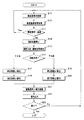
以下、図面を参照して本発明の実施の形態の内視鏡装置1について説明する。
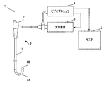
図1は、本実施の形態にかかる内視鏡装置1の全体の構成を示す構成図であり、図2は、光源装置6の構成を示す構成図である。図1に示すように内視鏡装置1は、内視鏡2と、光源装置6と、ビデオプロセッサ4と、モニタ5とを有して構成されている。 内視鏡2は、被検体9内に挿入される細長い挿入部3と、この挿入部3の基端側に連設される操作部7とを有している。挿入部3は、軟性を有する可撓管部の先端側に設けられた湾曲部3Aと、この湾曲部3Aの先端側に設けられた先端部3Bとを有して構成されている。先端部3Bには、被検体9内の観察対象部位9Aを撮像する撮像素子であるCCD16(図2参照)が内蔵されており、CCD16の撮像信号はビデオプロセッサ4を介して、モニタ5の表示画面に表示される。一方、光源装置6から供給される照射光は、挿入部3内に配設されたライトガイド15(図2参照)により挿入部3の先端部3Bまで伝達される。
<Embodiment>
Hereinafter, an
FIG. 1 is a configuration diagram illustrating an overall configuration of the
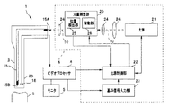
すなわち、図2に示すように、光源装置6の光源21から供給された光は、レンズ24等の光学系により光束10として集光され、光束10は光量調整部20にて光量が調整された後に、ライトガイド15の端部15Aに導光される。そして、照射光はライトガイド15内を通り、先端部3Bに配設されたライトガイド15のもう一方の端部15Bまで伝達され、端部15Bの端面に配設された図示しない照明光学系を介して、被検体9内の観察対象部位9Aを照明するようになっている。
That is, as shown in FIG. 2, the light supplied from the
ここで、モニタ5に表示される撮像画像の明るさ、すなわち輝度が、観察対象部位9Aと挿入部3の先端部3Bとの距離、または観察対象部位9Aの反射率等の違いにより変動してしまうと、術者は観察対象部位9Aの正確な認識が困難となる場合がある。このため、光源装置6の制御手段である光源制御部22は、ビデオプロセッサ4からの輝度信号が、基準信号入力部23から入力された基準輝度信号と略同一となるように、光量調整部20の駆動手段である駆動部26を制御する。
Here, the brightness of the captured image displayed on the
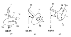
ここで、図3に示すように、本実施の形態の光量調整部20は、回転軸11を中心に鉛直面を回転駆動する絞り羽12により、光源からの光束10を制限する。図3は、絞り羽12による光量調整を説明するため、光束進行方向から見た絞り羽を示す平面図であり、(A)は全開状態を、(B)は部分的に閉じた状態を、(C)は全閉状態を示している。
Here, as shown in FIG. 3, the light
絞り羽12は、切り欠き部12Aを有する略楕円形状の先端部12aと、先端部から延びている細長い平板状の支持部12bとからなり、支持部12bの先端部12aと逆方向側の端部には図示しない駆動部26であるモータと回転角度を測定するポテンショメータ等が接続されている。ポテンショメータからの出力は、位置検出部25を介して、絞り羽12の位置、例えば、後述する重心角度として算出される。
The
モータが回転すると、絞り羽12は支持部12b上の回転軸11を中心に回転運動を行う。そして、光量調整部20の絞り羽12が光束10を遮断することで、光量調整部20から出射される光量が調整される。光源21からの光束10を回転駆動する絞り羽12により制限する光量調整部20は、簡単な構造でありながら、高速応答が可能である。
When the motor rotates, the
なお、絞り羽12が前記形状をしているのは、絞り羽12の応答速度を、より早くするためには絞り羽12をより軽くする必要があるためである。なお、前記形状の絞り羽12は、その重心が回転軸11からずれて、先端部12a内にある。
The reason why the
すなわち、光量調整部20は、その重心が回転軸に対して偏心した絞り羽12を用いることで、絞り羽12の質量を小さくし、高い周波数応答性を実現している。
That is, the light
なお、回転軸を中心とした円形の絞り羽を用いること、あるいは、支持部の回転軸をはさんで先端部と反対側に錘を取り付けることで、絞り羽の重心を回転軸上とすることは可能ではある。しかし、前記のような回転軸上に重心を有する絞り羽は重量が重くなり、応答速度が低下するため、高速で光量調整を行う必要のある、例えば内視鏡装置の光源装置には好ましくはない。 Use a circular diaphragm blade centered on the rotation axis, or attach a weight on the opposite side of the tip part across the rotation axis of the support part, so that the center of gravity of the diaphragm blade is on the rotation axis. Is possible. However, the diaphragm blade having the center of gravity on the rotation axis as described above is heavy, and the response speed is reduced. Therefore, it is necessary to adjust the light amount at a high speed, for example, preferably for a light source device of an endoscope apparatus. Absent.
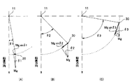
次に、図3および図4を用いて光量調整部20の絞り羽12の位置による自重の影響について説明する。図4は、絞り羽12の位置による自重の影響を説明するため、光束進行方向から見た絞り羽12を示す平面図であり、(A)は全開状態を、(B)は部分的に閉じた状態を、(C)は全閉状態を示している。なお、図3および図4において、θ1からθ3は、それぞれの状態における絞り羽12の重心30と回転軸11とを結ぶ直線が、鉛直方向に対してなす角度(以下、「重心角度θ」という。)を示している。
Next, the influence of the self-weight due to the position of the
絞り羽12は、絞り羽12が閉じる方向(図3(A)から(B)、または(B)から(C))に移動、言い換えれば上方向に回転する際には重力に逆らって回転する必要がある。反対に、絞り羽12は、絞り羽12が開く方向(図3(C)から(B)、または(B)から(A))に移動、言い換えれば下方向に回転する際には重力が補助力となって回転する。
The
すなわち、図4に示すように、質量がMの絞り羽12の重心角度がθの場合、絞り羽12の自重の回転方向成分である「Mg sinθ」が回転方向に作用する。そして、重心角度θが大きいほど、絞り羽12の自重の回転方向成分がより大きい。例えば、図4(B)の状態から図4(C)の状態に絞り羽12を回転する際には、絞り羽12の自重の回転方向成分が、「Mg sinθ2」から「Mg sinθ3」に増加するため、光源制御部22が絞り羽12を同一の出力信号で回転制御していると、絞り羽12の回転速度は遅くなる。逆に、図4(B)の状態から図4(A)の状態に絞り羽12が回転する際には、絞り羽12の自重の回転方向成分が、「Mg sinθ2」から「Mg sinθ1」に減少するため、光源制御部22が絞り羽12を同一の出力信号で回転制御していると、絞り羽12の回転速度は早くなる。しかし、本実施の形態の光源制御部22は、補正係数を用いて補正した出力信号にて回転制御するため絞り羽12の回転速度は安定している。
That is, as shown in FIG. 4, when the center of gravity angle of the
図5を用いて、上述した光源制御部22の動作を詳細に説明する。図5は、光源制御部22による制御のための補正係数を説明するための図である。図5(A)に示すように、絞り羽12の重心角度θにより絞り羽12の自重の回転方向成分は変化する。これに対して本実施の形態の光源制御部22は、絞り羽12の位置および回転方向に基づいて算出した補正係数を用いて補正した出力信号にて光量調整部22の駆動部26を制御する。
The operation of the light
すなわち、光源制御部22は、例えば、図5(B)に示すように、絞り羽12が、上方向、言い換えれば閉じる方向に回転する際には、補正関数αから補正係数αを算出して用いる。図5では、絞り羽12が重心角度θ2の現在位置から重心角度θ3の目標位置に移動する場合の補正係数α1は、α1=(Mg sinθ3)/(Mg sinθ2)であり、すなわち、現在位置の前記絞り羽の自重の回転方向成分と、目標位置の前記絞り羽の自重の回転方向成分との比である。なお、絞り羽12が重心角度θ2の位置の自重の回転方向成分「Mg sinθ2」を基準、すなわち1としている。
That is, for example, as shown in FIG. 5B, the light
α1と同様に重心角度θ1の目標位置に移動する場合の補正係数α2を算出し、図5(B)に示すように、曲線近似により、補正関数αを算出している。 Similar to α1, a correction coefficient α2 when moving to the target position of the center of gravity angle θ1 is calculated, and a correction function α is calculated by curve approximation as shown in FIG. 5B.
また、これに対して、例えば、図5(C)に示すように、絞り羽12が、下方向、言い換えれば開く方向に回転する際には、補正関数βから補正係数βを算出して用いる。図5では、絞り羽12が重心角度θ2の現在位置から重心角度θ1の目標位置に移動する場合の補正係数β1は、β1=(Mg sinθ2)/(Mg sinθ1)であり、すなわち、現在位置の前記絞り羽の自重の回転方向成分と、目標位置の前記絞り羽の自重の回転方向成分との比である。なお、絞り羽12が重心角度θ2の位置の自重の回転方向成分「Mg sinθ2」を基準、すなわち1としている。
On the other hand, for example, as shown in FIG. 5C, when the
β1と同様に重心角度θ3の目標位置に移動する場合の補正係数β2を算出し、図5(C)に示すように、曲線近似により、補正関数βを算出している。 Similar to β1, a correction coefficient β2 when moving to the target position of the center of gravity angle θ3 is calculated, and a correction function β is calculated by curve approximation as shown in FIG.
そして、光源制御部22は、位置検出部25が算出した重心角度θを用い、補正関数により算出した補正係数を用い補正した制御信号で駆動部26を制御する。ここで、制御信号は、駆動部に印加する電流、電圧または電力等である。
Then, the light
光源装置6は、その光源制御部22が、絞り羽12の自重の回転方向成分に基づいた補正係数を用いて制御することで、絞り羽12の回転方向または位置によらず、移動速度すなわち絞り羽12が現在位置から目標位置に到達するまでの時間が安定しているため、応答速度が一定であり、安定した光量制御が可能である。
The
次に、図6を用いて、光源制御部22の処理の流れを説明する。図6は、光源制御部22の処理の流れを説明するためのフローチャートである。
Next, the processing flow of the light
<ステップS11>
最初に、光源制御部22は、輝度信号をビデオプロセッサ4から取得する。輝度信号は、CCD16が取得した映像信号をビデオプロセッサ4が処理しモニタ5に表示される表示画面の平均的な明るさの情報である。あるいは、輝度信号として、モニタ5に表示される表示画面の特定の部分のみの情報を用いてもよい。
<Step S11>
First, the light
<ステップS12>
光源制御部22は、基準輝度信号を基準信号入力部23から取得する。基準輝度信号はモニタ5に表示される表示画面の明るさの目標値である。基準輝度信号は術者が基準信号入力部23に配設したダイヤル等で入力してもよいし、あるいは、ある時点のビデオプロセッサ4からの輝度信号を基準輝度信号として入力されてもよい。
<Step S12>
The light
<ステップS13>
光源制御部22は、輝度信号と基準輝度信号とを比較し、その差が所定値の範囲内であるかどうか判断する。輝度信号と基準輝度信号との差が所定値の範囲内(Yes)の場合には、光源制御部22は、絞り羽12を駆動する必要がないため、ステップS11からの動作を繰り返す。一方、輝度信号と基準輝度信号との差が所定値の範囲を越える(No)場合には、光源制御部22は、絞り羽12を駆動するために、ステップS14以下の動作を行う。
<Step S13>
The light
なお、ここで、輝度信号と基準輝度信号との差の所定値とは、術者あるいは光源装置6の設計時に決定される値であり、所定値が小さすぎると絞り羽12が常時、細かく駆動される状態となるため、光量調整部22のレスポンスの遅れ等の影響で、モニタ5の表示画面の明るさがちらつくことがある。反対に所定値が大きすぎると絞り羽12が駆動すべき状態であっても駆動されないため、モニタ5の表示画面の明るさが適当でなくなる。
Here, the predetermined value of the difference between the luminance signal and the reference luminance signal is a value determined when the operator or the
<ステップS14>
光源制御部22は、位置検出部25から絞り羽12の現在位置の情報、例えば重心角度θを取得する。
<Step S14>
The light
<ステップS15>
光源制御部22は、ステップS13で算出した輝度信号と基準輝度信号との差と、ステップS14で取得した絞り羽12の現在位置の情報から、絞り羽12の回転方向と、回転量すなわち駆動信号を算出する。ここで、回転方向は、絞り羽12を開ける方向、すなわち下方向か、あるいは、絞り羽12を閉める方向、すなわち上方向のいずれかである。また、回転量は、絞り羽12の位置、すなわち角度と、光量調整部20から射出される光量の関係を、予め求めておくことで、算出される。
<Step S15>
The light
<ステップS16>
光源制御部22は、ステップS15で算出した絞り羽12の回転方向から用いる補正係数を判断する。回転方向により制御信号に用いる補正係数が異なるためである。すなわち、光源制御部22は、絞り羽12の回転方向が上方向の場合には、ステップS17からの処理を、絞り羽12の回転方向が下方向の場合には、ステップS19からの処理を行う。
<Step S16>
The light
<ステップS17>
絞り羽12が上方向に回転する場合には、光源制御部22は、図5(B)に示すような、重心角度θと補正係数αの関係式である補正関数αを算出する。なお、補正関数αは毎回、算出する必要はなく、予め算出しておいた補正関数αを用いたのでよい。
<Step S17>
When the
<ステップS18>
絞り羽12が上方向に回転する場合には、光源制御部22は、絞り羽12の現在位置の重心角度θを補正関数αに代入することで、補正係数αを算出する。
<Step S18>
When the
<ステップS19>
絞り羽12が下方向に回転する場合には、光源制御部22は、図5(C)に示すような、重心角度θと補正係数βの関係式である補正関数βを算出する。なお、補正関数βは毎回、算出する必要はなく、予め算出しておいた補正関数βを用いたのでよい。
<Step S19>
When the
また、補正関数αおよび補正関数βは、図5(B)に示すように曲線近似式に限らず、直線近似式または理論式等であってもよい。あるいは、補正関数αおよび補正関数βは、関数式ではなく、一定間隔のθと補正係数からなる表形式等であってもよい。 Further, the correction function α and the correction function β are not limited to the curve approximation formula as shown in FIG. 5B, but may be a linear approximation formula or a theoretical formula. Alternatively, the correction function α and the correction function β may not be a function formula but may be a table format including θ and correction coefficients at regular intervals.
<ステップS20>
絞り羽12が下方向に回転する場合には、光源制御部22は、絞り羽12の現在位置の重心角度θを補正関数βに代入することで、補正係数βを算出する。
<Step S20>
When the
<ステップS21>
光源制御部22は、ステップS15で算出した駆動信号に、補正係数αまたは補正係数βを乗じて駆動信号を補正する。
<Step S21>
The
<ステップS22>
光源制御部22は、補正された駆動信号を駆動部26に出力する。駆動部26は補正された駆動信号に従い、絞り羽12を駆動する。
<Step S22>
The light
<ステップS23>
光源制御部22は、動作終了指示があるまで、ステップS11からの処理を繰り返す。
<Step S23>
The light
上記のように、本実施の形態の光源装置6の光量調整部20は、絞り羽12の位置および回転方向に基づいて補正された駆動信号で駆動部26を制御する光源制御部22を有するために、応答速度が高速でありながら安定した光量制御が可能である。また、本実施の形態の光源装置6を有する内視鏡装置1は、安定した光量制御が高速で可能であるため、例えば、内視鏡2の挿入部3を挿入しながらも観察を行っても、モニタ画面の明るさが安定している。
As described above, the light
<実施の形態の変形例>
以下、図面を参照して本発明の実施の形態の変形例の光源装置の絞り羽について説明する。本変形例の光源装置の基本構成は実施の形態の光源装置6と、ほぼ同じであるため、同じ構成要素には同じ符号を付し説明は省略し、以下、絞り羽についてのみ説明する。
<Modification of Embodiment>
Hereinafter, a diaphragm blade of a light source device according to a modification of the embodiment of the present invention will be described with reference to the drawings. Since the basic configuration of the light source device of the present modification is almost the same as that of the
なお、以下に示す本変形例の光源装置の絞り羽は、いずれも、実施の形態の光源装置6の絞り羽12と同様に、回転軸を中心に鉛直面を回転駆動し、回転軸に対して重心が偏心した形状を有している。
In addition, the diaphragm blades of the light source device of the present modification shown below are driven to rotate on the vertical plane around the rotation axis in the same manner as the
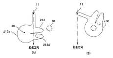
例えば、図7に示す絞り羽212は、光束10を遮蔽した場合(図7(B))に、光束10が先端部212Aの周囲から漏れることのないように、先端部212Aの切り欠き部212aの反対側が特に大きく構成されている。このため、絞り羽212は、特に、その重心30が回転軸11から大きく偏心している。
For example, the
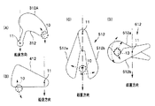
また、図8(A)に示す絞り羽312は、先端部312Aが上から下に回転すると、光束10が遮断される。すなわち、実施の形態の光源装置6の絞り羽12と比べると、絞り羽の回転方向と光束10の開閉方向が逆になっている。絞り羽312は、補正係数αと補正係数βを実施の形態の光源装置6と逆に用い補正された駆動信号で駆動される。
Further, in the
また、図8(B)に示す絞り羽412は、やはり実施の形態の光源装置6の絞り羽12と比べると、絞り羽の回転方向と光束の開閉方向が逆であり、かつ先端部と支持部が一体化した形状となっている。
In addition, the
また、図8(C)に示す絞り羽512は、2枚の絞り羽512aと512bとが互いに逆方向に回転することで、光束10を制限する。このような場合には、2枚の絞り羽512aと512bとが、それぞれ補正係数αと補正係数βのいずれか一方を用いて補正された駆動信号で駆動される。
In addition, the
やはり、図8(D)に示す絞り羽612は、2枚の絞り羽612aと612bとが互いに逆方向に回転することで、光束10を制限する。
Similarly, the
上記のような本変形例の絞り羽312〜612を有する光源装置は、いずれも本発明の実施の形態の光源装置6と同様の作用効果を奏することができる。また、本変形例の絞り羽312〜612を有する光源装置を備えた内視鏡装置も、本発明の実施の形態の光源装置6を有する内視鏡装置1と同様の作用効果を奏することができる。
Any of the light source devices having the
本発明は、上述した実施の形態および変形例に限定されるものではなく、本発明の要旨を変えない範囲において、種々の変更、改変等が可能である。 The present invention is not limited to the above-described embodiments and modifications, and various changes and modifications can be made without departing from the scope of the present invention.
1…内視鏡装置、2…内視鏡、3…挿入部、3A…湾曲部、3B…先端部、4…ビデオプロセッサ、5…モニタ、6…光源装置、7…操作部、9…被検体、9A…観察対象部位、10…光束、11…回転軸、12…絞り羽、15…ライトガイド、20…光量調整部、21…光源、22…光源制御部、23…基準信号入力部、24…レンズ、25…位置検出部、26…駆動部、30…重心、110…光束、111…回転軸、112…絞り羽、120…絞り羽部、126…モータ、130…重心、212、312、412、512、612…絞り羽、α…補正関数、β…補正関数、θ…重心角度
DESCRIPTION OF
Claims (3)
前記光量調整手段は、
回転軸を中心に鉛直面を回転駆動し、前記回転軸に対して重心が偏心した前記絞り羽と、
前記絞り羽の位置を検出する位置検出手段と、
前記絞り羽を回転駆動する駆動手段と、
前記駆動手段を制御する制御手段とを有し、
前記制御手段は、前記位置検出手段が検出した前記絞り羽の位置、および回転方向に基づいて前記駆動手段を制御し、当該駆動手段の制御は、前記絞り羽の自重の回転方向成分に基づいた補正係数を用いて行われることを特徴とする光源装置。 A light source device comprising a light source and a light amount adjusting means for limiting a light beam from the light source using a diaphragm blade,
The light amount adjusting means is
The diaphragm blades that rotate and drive the vertical plane around the rotation axis, and whose center of gravity is eccentric with respect to the rotation axis;
Position detecting means for detecting the position of the diaphragm blade;
Drive means for rotationally driving the diaphragm blades;
Control means for controlling the drive means,
The control means controls the driving means based on the position and rotation direction of the diaphragm blade detected by the position detection means, and the control of the driving means is based on the rotation direction component of the dead weight of the diaphragm blade. A light source device, which is performed using a correction coefficient .
Priority Applications (4)
| Application Number | Priority Date | Filing Date | Title |
|---|---|---|---|
| JP2007316121A JP5259167B2 (en) | 2007-12-06 | 2007-12-06 | Light source device and endoscope device |
| EP08020234A EP2067436B1 (en) | 2007-12-06 | 2008-11-20 | Light source apparatus and endoscope apparatus |
| CN2008101787733A CN101449962B (en) | 2007-12-06 | 2008-12-01 | Light source unit and endoscope unit |
| US12/329,737 US8294755B2 (en) | 2007-12-06 | 2008-12-08 | Light source apparatus and endoscope apparatus |
Applications Claiming Priority (1)
| Application Number | Priority Date | Filing Date | Title |
|---|---|---|---|
| JP2007316121A JP5259167B2 (en) | 2007-12-06 | 2007-12-06 | Light source device and endoscope device |
Publications (2)
| Publication Number | Publication Date |
|---|---|
| JP2009136491A JP2009136491A (en) | 2009-06-25 |
| JP5259167B2 true JP5259167B2 (en) | 2013-08-07 |
Family
ID=40299390
Family Applications (1)
| Application Number | Title | Priority Date | Filing Date |
|---|---|---|---|
| JP2007316121A Expired - Fee Related JP5259167B2 (en) | 2007-12-06 | 2007-12-06 | Light source device and endoscope device |
Country Status (4)
| Country | Link |
|---|---|
| US (1) | US8294755B2 (en) |
| EP (1) | EP2067436B1 (en) |
| JP (1) | JP5259167B2 (en) |
| CN (1) | CN101449962B (en) |
Families Citing this family (8)
| Publication number | Priority date | Publication date | Assignee | Title |
|---|---|---|---|---|
| CN103002791B (en) * | 2010-07-14 | 2015-09-09 | 奥林巴斯医疗株式会社 | Endoscope light source unit and endoscopic system |
| TWI459307B (en) * | 2011-07-20 | 2014-11-01 | Altek Corp | Device with object position detection function and detection method thereof |
| EP2796086A4 (en) * | 2012-09-18 | 2015-09-09 | Olympus Medical Systems Corp | LIGHT SOURCE DEVICE AND LIGHT SOURCE DEVICE LIGHTING CONTROL METHOD |
| CN103006171B (en) * | 2012-12-13 | 2015-07-29 | 深圳开立生物医疗科技股份有限公司 | Light supply apparatus and endoscope apparatus |
| CN104083144B (en) * | 2013-11-28 | 2016-02-03 | 北京华科创智健康科技股份有限公司 | The method and apparatus that a kind of fujinon electronic video endoscope image region brightness controls |
| CN107065170B (en) * | 2017-05-12 | 2019-07-05 | 重庆金山医疗器械有限公司 | Fujinon electronic video endoscope light source optical path control system |
| CN110691545B (en) * | 2017-06-02 | 2021-06-18 | 奥林巴斯株式会社 | Endoscope light source device |
| JP7115493B2 (en) * | 2017-11-01 | 2022-08-09 | ソニーグループ株式会社 | Surgical arm system and surgical arm control system |
Family Cites Families (12)
| Publication number | Priority date | Publication date | Assignee | Title |
|---|---|---|---|---|
| US4834071A (en) | 1987-07-13 | 1989-05-30 | Kabushiki Kaisha Toshiba | Illuminance controller for light source and endoscope including the same |
| US5087122A (en) | 1990-08-13 | 1992-02-11 | Laser Precision Corporation | Adjustable attenuator for optical transmission system |
| JP2577260Y2 (en) | 1990-11-20 | 1998-07-23 | 旭光学工業株式会社 | Light source device for endoscope |
| US5868666A (en) | 1993-11-26 | 1999-02-09 | Olympus Optical Co., Ltd. | Endoscope apparatus using programmable integrated circuit to constitute internal structure thereof |
| JP3523675B2 (en) | 1993-12-22 | 2004-04-26 | オリンパス株式会社 | Dimming circuit |
| JP3285264B2 (en) * | 1993-11-26 | 2002-05-27 | オリンパス光学工業株式会社 | Automatic light control device for endoscope |
| JP3676633B2 (en) | 1998-12-28 | 2005-07-27 | ペンタックス株式会社 | Endoscope diaphragm control device |
| US6473116B1 (en) | 1998-12-28 | 2002-10-29 | Asahi Kogaku Kogyo Kabushiki Kaisha | Electronic endoscope |
| JP2001137186A (en) * | 1999-11-18 | 2001-05-22 | Asahi Optical Co Ltd | Electronic endoscope |
| JP3995954B2 (en) * | 2001-03-02 | 2007-10-24 | ペンタックス株式会社 | Electronic endoscope device with automatic light control function |
| JP2003325446A (en) * | 2002-05-14 | 2003-11-18 | Olympus Optical Co Ltd | Light source device |
| JP5269346B2 (en) | 2007-05-10 | 2013-08-21 | オリンパスメディカルシステムズ株式会社 | Light source device and endoscope device |
-
2007
- 2007-12-06 JP JP2007316121A patent/JP5259167B2/en not_active Expired - Fee Related
-
2008
- 2008-11-20 EP EP08020234A patent/EP2067436B1/en not_active Not-in-force
- 2008-12-01 CN CN2008101787733A patent/CN101449962B/en not_active Expired - Fee Related
- 2008-12-08 US US12/329,737 patent/US8294755B2/en active Active
Also Published As
| Publication number | Publication date |
|---|---|
| CN101449962A (en) | 2009-06-10 |
| JP2009136491A (en) | 2009-06-25 |
| US8294755B2 (en) | 2012-10-23 |
| CN101449962B (en) | 2010-10-13 |
| EP2067436A1 (en) | 2009-06-10 |
| EP2067436B1 (en) | 2011-09-07 |
| US20090147079A1 (en) | 2009-06-11 |
Similar Documents
| Publication | Publication Date | Title |
|---|---|---|
| JP5259167B2 (en) | Light source device and endoscope device | |
| EP2878253B1 (en) | Wire driver for wire line and endoscope | |
| US9510736B2 (en) | Stereoscopic endoscope device having mechanism that changes an angle between optical axes of two imaging sensors | |
| US10441132B2 (en) | Method of controlling endoscopes, and endoscope system | |
| US9895143B2 (en) | Medical system and method of controlling medical instruments | |
| JP3345645B2 (en) | Body cavity observation device | |
| EP1854420A1 (en) | Treatment system and trocar | |
| EP3530228B1 (en) | Microscope device and control method | |
| JPS63182621A (en) | Light source device for endoscope | |
| JP2009077759A (en) | X-ray diagnostic equipment | |
| JP5499427B2 (en) | Endoscope camera and endoscope camera system | |
| JP5150388B2 (en) | Endoscope | |
| US20180071034A1 (en) | Medical manipulator system | |
| EP2979613B1 (en) | Device for endoscopic surgery | |
| JP3552737B2 (en) | Surgical microscope | |
| JP2019141590A (en) | Medical observation device comprising movable beam deflector and operation method thereof | |
| JP3977025B2 (en) | Endoscope processor | |
| JP2005292453A (en) | Display apparatus | |
| JP2003177326A (en) | Operating microscope | |
| KR102107593B1 (en) | x-ray indicate apparatus for c-arm and c-arm comprising the same | |
| WO2020084891A1 (en) | Medical bidirectional suturing system | |
| JP2002228943A (en) | Light source system for endoscope apparatus and endoscope apparatus | |
| JP2002272681A (en) | Endoscope device processor | |
| JP2006034456A (en) | Endoscope | |
| WO2014054770A1 (en) | Guide instrument for body cavity insertion tool |
Legal Events
| Date | Code | Title | Description |
|---|---|---|---|
| A621 | Written request for application examination |
Free format text: JAPANESE INTERMEDIATE CODE: A621 Effective date: 20101005 |
|
| A977 | Report on retrieval |
Free format text: JAPANESE INTERMEDIATE CODE: A971007 Effective date: 20120726 |
|
| A131 | Notification of reasons for refusal |
Free format text: JAPANESE INTERMEDIATE CODE: A131 Effective date: 20120814 |
|
| A521 | Request for written amendment filed |
Free format text: JAPANESE INTERMEDIATE CODE: A523 Effective date: 20121015 |
|
| TRDD | Decision of grant or rejection written | ||
| A01 | Written decision to grant a patent or to grant a registration (utility model) |
Free format text: JAPANESE INTERMEDIATE CODE: A01 Effective date: 20130409 |
|
| A61 | First payment of annual fees (during grant procedure) |
Free format text: JAPANESE INTERMEDIATE CODE: A61 Effective date: 20130424 |
|
| FPAY | Renewal fee payment (event date is renewal date of database) |
Free format text: PAYMENT UNTIL: 20160502 Year of fee payment: 3 |
|
| R151 | Written notification of patent or utility model registration |
Ref document number: 5259167 Country of ref document: JP Free format text: JAPANESE INTERMEDIATE CODE: R151 |
|
| S111 | Request for change of ownership or part of ownership |
Free format text: JAPANESE INTERMEDIATE CODE: R313111 |
|
| R350 | Written notification of registration of transfer |
Free format text: JAPANESE INTERMEDIATE CODE: R350 |
|
| S531 | Written request for registration of change of domicile |
Free format text: JAPANESE INTERMEDIATE CODE: R313531 |
|
| R350 | Written notification of registration of transfer |
Free format text: JAPANESE INTERMEDIATE CODE: R350 |
|
| R250 | Receipt of annual fees |
Free format text: JAPANESE INTERMEDIATE CODE: R250 |
|
| R250 | Receipt of annual fees |
Free format text: JAPANESE INTERMEDIATE CODE: R250 |
|
| R250 | Receipt of annual fees |
Free format text: JAPANESE INTERMEDIATE CODE: R250 |
|
| R250 | Receipt of annual fees |
Free format text: JAPANESE INTERMEDIATE CODE: R250 |
|
| LAPS | Cancellation because of no payment of annual fees |