JP2005292453A - Display apparatus - Google Patents
Display apparatus Download PDFInfo
- Publication number
- JP2005292453A JP2005292453A JP2004107251A JP2004107251A JP2005292453A JP 2005292453 A JP2005292453 A JP 2005292453A JP 2004107251 A JP2004107251 A JP 2004107251A JP 2004107251 A JP2004107251 A JP 2004107251A JP 2005292453 A JP2005292453 A JP 2005292453A
- Authority
- JP
- Japan
- Prior art keywords
- light
- unit
- projection
- display device
- light shielding
- Prior art date
- Legal status (The legal status is an assumption and is not a legal conclusion. Google has not performed a legal analysis and makes no representation as to the accuracy of the status listed.)
- Withdrawn
Links
- 230000003287 optical effect Effects 0.000 claims description 16
- 238000001514 detection method Methods 0.000 claims description 5
- 238000001356 surgical procedure Methods 0.000 abstract 1
- 210000001747 pupil Anatomy 0.000 description 6
- 230000000694 effects Effects 0.000 description 2
- 230000002093 peripheral effect Effects 0.000 description 2
- 230000000903 blocking effect Effects 0.000 description 1
- 238000010586 diagram Methods 0.000 description 1
- 210000003128 head Anatomy 0.000 description 1
- 238000005286 illumination Methods 0.000 description 1
- 238000003384 imaging method Methods 0.000 description 1
- 238000000034 method Methods 0.000 description 1
Images

Landscapes
- Projection Apparatus (AREA)
- Transforming Electric Information Into Light Information (AREA)
Abstract
Description
本発明は、光の投射を受けて観察者が観察する画像を表示する表示装置に関する。 The present invention relates to a display device that receives light projection and displays an image observed by an observer.
特許文献1の表示装置は投射機からの信号光をホログラムスクリーンに投射し、その映像を観察者が観察するようにしたものである。また、特許文献2の表示装置は2台の投射機からの光束をフレネルレンズに投射し、その視差の有する別々の画像を観察者が左右の眼で観察することにより立体的に観察できるようにしたものである。特許文献1の表示装置のホログラムスクリーンでは投射機からの光束を観察者の方向に回折する作用を持ち、特許文献2の表示装置ではフレネルレンズを利用することにより投射機からの光束を観察者の瞳に集光させる。
上述した特許文献1,2の表示装置いずれの場合でも、投射機の近傍に照明用蛍光灯などの光源体が存在していると、その光源体から発せられる光束が観察者の瞳に入ってしまうことになる。すなわち、投射機からホログラムスクリーンやフレネルレンズに向かう光軸の延長上に蛍光灯などの光源体が存在する場合にはその蛍光灯等の光も同時に観察者の瞳に入ってしまう。このため、非常に観察がしづらい状況となる。特に、医療の分野では手術室内にある無影灯などの光の影響を受け易い。
In any case of the display devices of
本発明は上述したような課題に着目してなされたもので、その目的とするところは投射装置を用いて表示部に表示した画像を観察する場合において、手術室の無影灯等の外光による影響を防止するようにした表示装置を提供することにある。 The present invention has been made paying attention to the problems as described above, and the object is to observe external light such as an operating light in an operating room when observing an image displayed on a display unit using a projection device. It is an object of the present invention to provide a display device that can prevent the influence of the above.
請求項1に係る発明は、投影光の投射を受けて観察者が観察する画像を表示する表示部と、上記投影光を上記表示部に向けて投射する投射部と、上記投影光以外の外光が上記表示部に入射することを阻止する遮光部と、を備えることを特徴とする表示装置である。
請求項2に係る発明は、上記遮光部は上記投射部から上記表示部に向かう投射光軸の後方に配置されていることを特徴とする請求項1に記載の表示装置である。
請求項3に係る発明は、上記遮光部は上記表示部の近傍に配置されていることを特徴とする請求項1に記載の表示装置である。
請求項4に係る発明は、上記表示部に設けられ、上記表示部に向けて投射する投影光以外の外光の光量を検知する検知手段と、上記検知手段からの信号に基づき上記遮光部の遮光形態を変更する遮光部可変手段と、を備えることを特徴とする請求項1、請求項2または請求項3に記載の表示装置である。
According to a first aspect of the present invention, there is provided a display unit that displays an image that an observer observes upon receiving projection light, a projection unit that projects the projection light toward the display unit, and an external device other than the projection light. A display device comprising: a light shielding unit that prevents light from entering the display unit.
The invention according to
The invention according to claim 3 is the display device according to claim 1, wherein the light-shielding portion is disposed in the vicinity of the display portion.
According to a fourth aspect of the present invention, there is provided a detection unit that is provided in the display unit and detects the amount of external light other than the projection light projected toward the display unit, and the light blocking unit based on a signal from the detection unit. The display device according to claim 1, further comprising: a light shielding unit varying unit that changes a light shielding mode.
本発明によれば、例えば手術室の無影灯等の外光の影響を受けずに常に良好に画像の観察を行なうことができる。 According to the present invention, it is possible to always observe an image satisfactorily without being affected by external light such as a surgical light in an operating room.
〔第1実施形態〕
本発明の第1実施形態に係る表示装置を図1から図3を参照して説明する。
[First Embodiment]
A display device according to a first embodiment of the present invention will be described with reference to FIGS.
(構成)
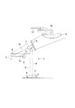
図1は本実施形態に係る表示装置の構成を概略的に示した説明図である。同図中符号1は画像を投影するためのプロジェクター(投射部)であり、同図中符号2は上記プロジェクター1から投影される画像を反射し、その画像を観察者3の瞳に導光するパネル部である。このプロジェクター1とパネル部2を含む表示装置4は支持手段としての架台5に支持されている。
(Constitution)
FIG. 1 is an explanatory diagram schematically showing the configuration of the display device according to the present embodiment. Reference numeral 1 in the figure denotes a projector (projection unit) for projecting an image.
上記架台5は上記表示装置4を移動させるためのキャスター6を有したベース7と、このベース7の上面に配置された支柱8と、この支柱8に固定されて略水平方向に伸びる支持アーム9とを備える。上記プロジェクター1は上記支柱8の上端に昇降・回転・傾斜自在に支持されており、上記パネル部2は上記支持アーム9の先端に移動調整自在に支持されている。すなわち、プロジェクター1及びパネル部2は架台5により両者の相対的な関係を保持するように支持されていると同時に両者の相対的な位置関係の調整も可能なように支持されている。そして、図1に示すように、プロジェクター1と観察者3はパネル部2の前方に位置する。
The
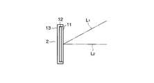
上記パネル部2は、図2に示す如く、前面側に位置するホログラムスクリーン11と背面側に位置するフレネルレンズ12とを重ね合わせてパネル枠13に取り付けてなる。図1に示すように、プロジェクター1の投射光軸L1はホログラムスクリーン11の前面に対して斜め上方に傾いて延びている。また、観察者3はホログラムスクリーン11の前面に垂直な観察軸L2の前方に位置する場所から上記パネル部2を観察することが適当である。
As shown in FIG. 2, the
図1に示すように、プロジェクター1の後端部には遮光手段としての遮光板(遮光部)14が固定され、この遮光板14はプロジェクター1の後方近傍に配置される。また、この遮光板14はホログラムスクリーン11の光束取り込み範囲(図1において破線で示す内側領域)と同等の面積を有し、その光束取り込み範囲の領域15を後方から遮蔽する。また、プロジェクター1の後方には無影灯(光源)16が設置され、この無影灯16は例えば手術室の天井17に移動自在に支持されたアーム18により保持されている。
As shown in FIG. 1, a light shielding plate (light shielding portion) 14 as a light shielding means is fixed to the rear end portion of the projector 1, and the
(作用)
次に、上記表示装置4を使用する場合の作用について説明する。プロジェクター1には図示しない手術用顕微鏡や内視鏡などの撮像装置により撮像したものの映像信号が入力される。プロジェクター1から投影された信号光としての画像がパネル部2のホログラムスクリーン11で回折し、フレネルレンズ12で反射することにより観察者3の瞳に集光し、観察者3は投射された表示像を視認することができる。このような観察作用は上述した技術と同様である。
(Function)
Next, the operation when the display device 4 is used will be described. The projector 1 receives a video signal of an image captured by an imaging device such as a surgical microscope or an endoscope (not shown). The image as the signal light projected from the projector 1 is diffracted by the
手術の進行により表示装置4の移動が必要な状況になった場合はキャスター6により表示装置4全体を移動させる。表示装置4を移動させることにより、パネル部2と無影灯16の位置関係が図1に示す状態の場合、無影灯16からの光の一部(図1実線で示すもの)はパネル部2の方向へと向かう。このとき、ホログラムスクリーン11の光束取り込み範囲の領域15には遮光板14が位置しているため、無影灯16の光束がホログラムスクリーン11に入り込むことがない。したがって、観察者3の瞳に無影灯16からの光束が入り込み、観察がしづらい状況となることを回避できる。
When the display device 4 needs to be moved due to the progress of the operation, the entire display device 4 is moved by the
(効果)
本実施形態によれば、表示装置4が手術室内のどのポジションに配置されても無影灯16等による外光の影響を受けることなく良好な観察を行なうことができる。
(effect)
According to the present embodiment, good observation can be performed without being affected by external light from the
〔第2実施形態〕
本発明の第2実施形態に係る表示装置を図4から図6を参照して説明する。上述した第1実施形態と同様の構成のものについては同一の符号を付してその詳細な説明を省略する。
[Second Embodiment]
A display device according to a second embodiment of the present invention will be described with reference to FIGS. The same components as those in the first embodiment described above are denoted by the same reference numerals, and detailed description thereof is omitted.
(構成)
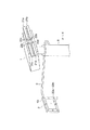
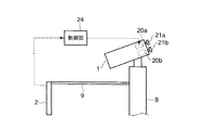
図4に示すように、パネル部2のパネル枠13の周縁はホログラムスクリーン11及びフレネルレンズ12の周囲から外方に突き出して露出しており、この露出したパネル枠13の周縁部の前面には複数の光センサー20a〜20hが配置されている。各光センサー20a〜20hはホログラムスクリーン11周囲のパネル枠13の縁にほぼ等間隔でその全周にわたり配置されている。また、光センサー20a〜20hはホログラムスクリーン11とプロジェクター1とを結ぶ(光軸L1)方向への指向性を備えることが望ましい。
(Constitution)
As shown in FIG. 4, the peripheral edge of the
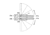
また、図4に示すように、プロジェクター1の背面には複数の遮光部材21a〜21dが配置され、プロジェクター1の本体に取り付けられている。各遮光部材21a〜21dは要となる枢支点に回動軸22a〜22dを備え、この回動軸22a〜22dを中心として図5に点線で示す如く扇状に広がり得る伸縮または折畳み自在なものであり、回動軸22a〜22dを要とする扇様の開閉が可能なものである。図4及び図5に示すように、遮光部材21a〜21dの回動軸22a〜22dの軸上にはモーター23a〜23dが配置され、これらのモーター23a〜23dにより上記各遮光部材21a〜21dを個々に開閉する駆動が行なわれる。
As shown in FIG. 4, a plurality of
図5に示すように、各モーター23a〜23dの動作は制御部24でそれぞれ制御がなされる。制御部24は光センサー20a〜20hからの信号に基づき、各モーター23a〜23dへ駆動信号を送信し、遮光部材21a〜21dの開閉動作を制御する。
As shown in FIG. 5, the operations of the
(作用)
本実施形態に係る表示装置4を使用する状況において、上記プロジェクター1の光軸L1 方向に沿って無影灯16からの外光がパネル部2に当ると、光センサー20a〜20hがその光量を感知する。光センサー20a〜20dはそれぞれ規定のしきい値を超えると、制御部24へ信号を送信する。制御部24では各光センサー20a〜20hの受光の有無により、モーター23a〜23dへ選択的に駆動信号を発信し、対応するモーター23a〜23dを駆動し、所定の遮光部材21a〜21dを個別的に開く。開いた遮光部材21a〜21dにより光センサー20a〜20dへの無影灯16からの外光が遮断され、この時点で、制御部24はモーター23a〜23dへの駆動信号を停止する。すなわち、制御部24ではパネル部2の一部に外光が当っている状態ではその外光が当っている位置に対応した範囲の遮光部材21a〜21dが部分的に開くような制御が行なわれる。そのため、パネル部2に外光が全く当っていない状態では全ての遮光部材21a〜21dが閉じた状態となる。
(Function)
In a situation where the display device 4 according to the present embodiment is used, when external light from the
(効果)
本実施形態によれば、遮光手段を構成する遮光部材21a〜21dの広がりが必要最小限で済むため、表示装置4の移動時に無影灯16等との干渉が極力少なくなる。また、表示装置4の収納時の省スペース化が図れる。
(effect)
According to the present embodiment, since the spread of the
なお、本発明は前述した各実施形態のものに限定されるものではなく、他の形態にも適用が可能なものである。例えば遮光板をパネル部の近傍に配置してもよい。また、前述した実施形態ではホログラムスクリーンを利用した表示部としたが、本発明は投射機からの光をフレネルレンズに投射し、その画像を観察者が左右の眼で観察するようにする表示装置等、他の形式の表示装置にも適用が可能なものである。 The present invention is not limited to the above-described embodiments, and can be applied to other forms. For example, a light shielding plate may be disposed in the vicinity of the panel portion. In the above-described embodiment, the display unit uses the hologram screen. However, the present invention projects the light from the projector onto the Fresnel lens and allows the observer to observe the image with the left and right eyes. The present invention can also be applied to other types of display devices.
前述した説明によれば、以下の事項またはそれらの事項を組み合わせた事項の発明が得られる。
<付記>
1.投影光を照射する投射装置と、上記投射装置からの投影光を観察者の方向に回折し集光するためのホログラムスクリーンとフレネルレンズを有した表示パネル部と、を備えた表示装置において、上記投射装置と、上記表示パネル部を保持するための支持手段と、上記投射装置の近傍に配置された遮光手段を有することを特徴とする表示装置。
2.上記遮光手段は上記投射装置の表示パネル部に向かう光軸の延長上に配置されていることを特徴とする第1項に記載の表示装置。
3.上記遮光手段の面積を変更するための遮光面積可変手段を有することを特徴とする第1,2項に記載の表示装置。
4.上記支持手段は床面に対し移動可能なものであって、キャスターを有することを特徴とする第1,2,3項に記載の表示装置。
5.上記表示パネル部に配置された光量を検知するための検知手段と、上記検知手段からの信号に基づき上記遮光範囲を可変する遮光手段と、上記遮光手段による遮光手段の面積を制御するための制御手段とを有することを特徴とする表示装置。
6.上記検知手段がホログラムスクリーン近傍に配置された光センサーであることを特徴とする第5項に記載の表示装置。
According to the above description, the invention of the following items or a combination of these items can be obtained.
<Appendix>
1. In a display device comprising: a projection device that irradiates projection light; and a display panel having a hologram screen and a Fresnel lens for diffracting and condensing projection light from the projection device in the direction of an observer, A display device comprising: a projection device; a support unit for holding the display panel unit; and a light shielding unit disposed in the vicinity of the projection device.
2. 2. The display device according to claim 1, wherein the light shielding means is disposed on an extension of an optical axis toward the display panel portion of the projection device.
3. The display device according to any one of
4). 4. The display device according to any one of
5). Detection means for detecting the amount of light arranged on the display panel unit, light shielding means for changing the light shielding range based on a signal from the detection means, and control for controlling the area of the light shielding means by the light shielding means And a display device.
6). 6. The display device according to
1…プロジェクター
2…パネル部
3…観察者
4…表示装置
5…架台
11…ホログラムスクリーン
12…フレネルレンズ
13…パネル枠
14…遮光板
16…無影灯
DESCRIPTION OF SYMBOLS 1 ...
Claims (4)
上記投影光を上記表示部に向けて投射する投射部と、
上記投影光以外の外光が上記表示部に入射することを阻止する遮光部と、
を備えることを特徴とする表示装置。 A display unit that displays an image observed by an observer in response to projection of projection light;
A projection unit that projects the projection light toward the display unit;
A light-shielding part that prevents outside light other than the projection light from entering the display part;
A display device comprising:
上記検知手段からの信号に基づき上記遮光部の遮光形態を変更する遮光部可変手段と、
を備えることを特徴とする請求項1、請求項2または請求項3に記載の表示装置。 A detecting means provided in the display unit for detecting the amount of external light other than the projection light projected toward the display unit;
A light shielding portion variable means for changing a light shielding form of the light shielding portion based on a signal from the detection means;
The display device according to claim 1, 2, or 3.
Priority Applications (1)
| Application Number | Priority Date | Filing Date | Title |
|---|---|---|---|
| JP2004107251A JP2005292453A (en) | 2004-03-31 | 2004-03-31 | Display apparatus |
Applications Claiming Priority (1)
| Application Number | Priority Date | Filing Date | Title |
|---|---|---|---|
| JP2004107251A JP2005292453A (en) | 2004-03-31 | 2004-03-31 | Display apparatus |
Publications (1)
| Publication Number | Publication Date |
|---|---|
| JP2005292453A true JP2005292453A (en) | 2005-10-20 |
Family
ID=35325442
Family Applications (1)
| Application Number | Title | Priority Date | Filing Date |
|---|---|---|---|
| JP2004107251A Withdrawn JP2005292453A (en) | 2004-03-31 | 2004-03-31 | Display apparatus |
Country Status (1)
| Country | Link |
|---|---|
| JP (1) | JP2005292453A (en) |
Cited By (4)
| Publication number | Priority date | Publication date | Assignee | Title |
|---|---|---|---|---|
| KR100850719B1 (en) * | 2006-12-04 | 2008-08-06 | 삼성전자주식회사 | Image projector |
| JP2012508063A (en) * | 2008-11-10 | 2012-04-05 | ステリス コーポレーション | Method and apparatus for electronically controlling irradiation of surgical lighting |
| CN107635308A (en) * | 2016-05-31 | 2018-01-26 | 成都九十度工业产品设计有限公司 | A control method based on the control system of intelligent medical shadowless lamp equipment |
| WO2018131262A1 (en) | 2017-01-11 | 2018-07-19 | ソニー株式会社 | Information processing device, information processing method, program, screen, and information drawing system |
-
2004
- 2004-03-31 JP JP2004107251A patent/JP2005292453A/en not_active Withdrawn
Cited By (7)
| Publication number | Priority date | Publication date | Assignee | Title |
|---|---|---|---|---|
| KR100850719B1 (en) * | 2006-12-04 | 2008-08-06 | 삼성전자주식회사 | Image projector |
| JP2012508063A (en) * | 2008-11-10 | 2012-04-05 | ステリス コーポレーション | Method and apparatus for electronically controlling irradiation of surgical lighting |
| CN107635308A (en) * | 2016-05-31 | 2018-01-26 | 成都九十度工业产品设计有限公司 | A control method based on the control system of intelligent medical shadowless lamp equipment |
| WO2018131262A1 (en) | 2017-01-11 | 2018-07-19 | ソニー株式会社 | Information processing device, information processing method, program, screen, and information drawing system |
| JPWO2018131262A1 (en) * | 2017-01-11 | 2019-11-21 | ソニー株式会社 | Information processing apparatus, information processing method, program, screen, and information drawing system |
| JP7067488B2 (en) | 2017-01-11 | 2022-05-16 | ソニーグループ株式会社 | Information processing equipment, information processing methods, and programs |
| US11532250B2 (en) | 2017-01-11 | 2022-12-20 | Sony Corporation | Information processing device, information processing method, screen, and information drawing system |
Similar Documents
| Publication | Publication Date | Title |
|---|---|---|
| US12465193B2 (en) | Microsurgery system for displaying in real-time magnified digital image sequences of an operated area | |
| US7114849B2 (en) | Medical imaging device | |
| EP1736097A1 (en) | Ophthalmic apparatus | |
| JP2017104401A5 (en) | Medical diagnostic imaging equipment | |
| JP2002224038A (en) | Fundus camera | |
| JP2003233031A5 (en) | ||
| JP2009077759A (en) | X-ray diagnostic equipment | |
| US9706129B2 (en) | Image recording method having adaptive marking light emission and such an image recording device | |
| JP2006071544A (en) | Camera obscura device for fluorescence observation, fluorescence observation system, and fluorescence observation method | |
| JP2005292453A (en) | Display apparatus | |
| JP2000089123A (en) | Surgical microscope | |
| WO2019103052A1 (en) | Projection device | |
| JP2010011916A (en) | Endoscope | |
| JP2017181588A (en) | Projection apparatus, shielding object, projection method, and projection program | |
| JP3165716B2 (en) | Fundus camera | |
| JP6845983B2 (en) | Slit lamp | |
| JP2000214514A5 (en) | ||
| JP2005318937A (en) | Display device | |
| JP2003235810A (en) | Ophthalmologic apparatus | |
| JP3809267B2 (en) | Ophthalmic imaging equipment | |
| JP5515907B2 (en) | Image display device | |
| JP2006102100A (en) | Imaging device and illuminator | |
| JP4125091B2 (en) | Ophthalmic imaging equipment | |
| JPWO2018088236A1 (en) | Image processing apparatus and method, and program | |
| JP2006189467A (en) | Light quantity control device and projector apparatus using the same |
Legal Events
| Date | Code | Title | Description |
|---|---|---|---|
| A300 | Application deemed to be withdrawn because no request for examination was validly filed |
Free format text: JAPANESE INTERMEDIATE CODE: A300 Effective date: 20070605 |