JP2017181588A - Projection device, shield, projection method and projection program - Google Patents
Projection device, shield, projection method and projection program Download PDFInfo
- Publication number
- JP2017181588A JP2017181588A JP2016064432A JP2016064432A JP2017181588A JP 2017181588 A JP2017181588 A JP 2017181588A JP 2016064432 A JP2016064432 A JP 2016064432A JP 2016064432 A JP2016064432 A JP 2016064432A JP 2017181588 A JP2017181588 A JP 2017181588A
- Authority
- JP
- Japan
- Prior art keywords
- projection
- vehicle
- information
- photographing
- sun visor
- Prior art date
- Legal status (The legal status is an assumption and is not a legal conclusion. Google has not performed a legal analysis and makes no representation as to the accuracy of the status listed.)
- Pending
Links
Images


Abstract
Description
本発明は、投影装置、遮蔽物、投影方法及び投影用プログラムの技術分野に属し、より詳細には、車両の運転者又は同乗者等に視認させる画像を投影により表示させる投影装置、投影方法及び当該投影用プログラム並びに遮蔽物の技術分野に属する。 The present invention belongs to a technical field of a projection device, a shielding object, a projection method, and a projection program. More specifically, the present invention relates to a projection device, a projection method, and a projection method for displaying an image to be visually recognized by a driver or a passenger of a vehicle. It belongs to the technical field of the projection program and the shielding object.
一般に、例えば運転席に座っている運転者の視点から見た場合、車両には、運転者の死角となる領域を車両外に生じさせる遮蔽物が存在する。このような車両の遮蔽物としては、例えばピラーや、降ろした状態のサンバイザ等が挙げられる。このような死角の存在は、例えば小さな子供がその死角となる領域に入ってしまう場合等、安全運転上の大きな問題である。この点に鑑みた先行技術が記載されている文献として、例えば下記特許文献1が挙げられる。下記特許文献1に開示されている技術では、サンバイザやドア等の、可動式で運転者の視野を阻害する車両の部材の車室側に、液晶ディスプレイ等のディスプレイを備えさせる。そして、運転者の位置を示す位置情報と、上記車両の部材の状態と、に基づき、カメラ等により撮影された車両外の画像から、上記車両の部材により死角となる領域の画像を切り出し、当該車両の部材の状態に応じた補正を加えた上で、上記ディスプレイに表示する構成とされている。
In general, when viewed from the viewpoint of a driver sitting in a driver's seat, for example, the vehicle has a shield that generates a blind spot outside the vehicle. Examples of such a vehicle shield include a pillar and a sun visor in a lowered state. The existence of such a blind spot is a serious problem in safe driving, for example, when a small child enters an area where the blind spot is formed. As a document describing the prior art in view of this point, for example, the following
しかしながら、上記特許文献1に記載されている技術によると、
(ア)例えばサンバイザの内側にディスプレイを備えさせるとすると、その厚さや大きさに起因して、サンバイザとしての利便性に問題がある、
(イ)当該ディスプレイの存在により、サンバイザとして従来から備えられている、鏡やカードホルダ等を装着可能な機能を利用することができない、
(ウ)当該ディスプレイの存在によりサンバイザとしての装飾性が損なわれる、
といった問題点があった。
However, according to the technique described in
(A) For example, if a display is provided inside the sun visor, there is a problem in convenience as a sun visor due to its thickness and size.
(A) Due to the presence of the display, it is not possible to use a function that can be attached to a mirror, a card holder, or the like that has been conventionally provided as a sun visor.
(C) The presence of the display impairs decoration as a sun visor.
There was a problem.
そこで本発明は、上記の各問題点に鑑みて為されたもので、その課題の一例は、例えばサンバイザ等の遮蔽物としての元来の機能を損なうことなく、当該遮蔽物により実際には視認できなくなる死角領域を搭乗者に視認させることが可能な投影装置、投影方法及び当該投影用プログラム並びに遮蔽物を提供することにある。 Therefore, the present invention has been made in view of the above-described problems, and one example of the problem is that the original function as a shielding object such as a sun visor is not visually impaired by the shielding object. It is an object of the present invention to provide a projection device, a projection method, a projection program, and a shielding object capable of causing a passenger to visually recognize a blind spot area that cannot be obtained.
上記の課題を解決するために、請求項1に記載の発明は、車両の外に向けた搭乗者の視野を遮り且つ前記車両内に備えられた可動式のサンバイザ等の遮蔽物により前記搭乗者の死角となる前記車両外の死角領域をカメラ等の撮影手段により撮影して得られた撮影情報を補正した補正撮影情報に相当する投影画像が投影される前記遮蔽物の、前記搭乗者との関係における状態を検出する角度センサ等の検出手段と、前記検出された状態を示す状態情報に基づいて、前記撮影情報を補正して前記補正撮影情報を生成する画像処理部等の補正手段と、前記生成された補正撮影情報に相当する前記投影画像を、プロジェクタ等の投影手段を用いて前記遮蔽物に投影させる画像処理部等の投影制御手段と、を備える。
In order to solve the above-mentioned problem, the invention according to
上記の課題を解決するために、請求項8に記載の発明は、車両において実行される投影方法において、車両の外に向けた搭乗者の視野を遮り且つ前記車両内に備えられた可動式のサンバイザ等の遮蔽物により前記搭乗者の死角となる前記車両外の死角領域をカメラ等の撮影手段により撮影して得られた撮影情報を補正した補正撮影情報に相当する投影画像が投影される前記遮蔽物の、前記搭乗者との関係における状態を検出する検出工程と、前記検出された状態を示す状態情報に基づいて、前記撮影情報を補正して前記補正撮影情報を生成する補正工程と、前記生成された補正撮影情報に相当する前記投影画像を、プロジェクタ等の投影手段を用いて前記遮蔽物に投影させる投影制御工程と、を含む。 In order to solve the above-mentioned problem, an invention according to claim 8 is a projection method executed in a vehicle, wherein a movable type provided in the vehicle and blocking a passenger's field of view toward the outside of the vehicle. A projection image corresponding to corrected shooting information obtained by correcting shooting information obtained by shooting a blind spot area outside the vehicle, which is a blind spot of the occupant, by a shooting means such as a camera is projected by a shield such as a sun visor. A detection step of detecting a state of the shield in relation to the passenger, a correction step of correcting the shooting information and generating the corrected shooting information based on the state information indicating the detected state; A projection control step of projecting the projection image corresponding to the generated corrected photographing information onto the shielding object using projection means such as a projector.
上記の課題を解決するために、請求項9に記載の発明は、車両に搭載されているコンピュータを、前記車両の外に向けた搭乗者の視野を遮り且つ前記車両内に備えられた可動式のサンバイザ等の遮蔽物により前記搭乗者の死角となる前記車両外の死角領域をカメラ等の撮影手段により撮影して得られた撮影情報を補正した補正撮影情報に相当する投影画像が投影される前記遮蔽物の、前記搭乗者との関係における状態を検出する検出手段、前記検出された状態を示す状態情報に基づいて、前記撮影情報を補正して前記補正撮影情報を生成する補正手段、及び、前記生成された補正撮影情報に相当する前記投影画像を、プロジェクタ等の投影手段を用いて前記遮蔽物に投影させる投影制御手段、として機能させる。 In order to solve the above-mentioned problem, the invention according to claim 9 is a movable type in which a computer mounted on a vehicle blocks a field of view of a passenger facing outside the vehicle and is provided in the vehicle. A projection image corresponding to corrected shooting information obtained by correcting shooting information obtained by shooting a blind spot area outside the vehicle, which is a blind spot of the occupant, by a shooting unit such as a camera is projected by a shield such as a sun visor. Detecting means for detecting a state of the shield in relation to the occupant, correcting means for correcting the photographing information based on state information indicating the detected state, and generating the corrected photographing information; The projection image corresponding to the generated corrected photographing information is caused to function as a projection control unit that projects the projection image onto the shielding object using a projection unit such as a projector.
請求項1、請求項8又は請求項9のいずれか一項に記載の発明によれば、車両外の死角領域を撮影して得られた撮影情報を補正した補正撮影情報に相当する投影画像が投影される遮蔽物の状態を検出する。そして、当該検出された状態を示す状態情報に基づいて補正撮影情報を生成し、その補正撮影情報に相当する投影画像を遮蔽物に投影させる。よって、投影画像が投影される遮蔽物の状態に基づいて補正された補正撮影情報に相当する投影画像を、投影手段によりその遮蔽物に光学的に投影させるので、遮蔽物自体の元来の機能を損なうことなく、遮蔽物により実際には視認できなくなる死角領域を搭乗者に視認させることができる。
According to the invention according to any one of
上記の課題を解決するために、請求項2に記載の発明は、請求項1に記載の投影装置において、前記遮蔽物は、前記死角領域に向いた前記搭乗者の視線の方向と交差する方向の軸を中心として回動可能に前記車両に備えられており、前記検出手段は、前記搭乗者との関係における前記遮蔽物の前記回動の角度を前記状態として検出し、前記補正手段は、前記検出された角度を示す前記状態情報に基づき、前記撮影情報に対して台形補正処理を施して前記補正撮影情報を生成するように構成される。
In order to solve the above-mentioned problem, the invention according to
請求項2に記載の発明によれば、請求項1に記載の発明の作用に加えて、遮蔽物が、死角領域に向いた搭乗者の視線の方向と交差する方向の軸を中心として回動可能に備えられている。そして、搭乗者との関係における遮蔽物の回動の角度が検出され、その角度を示す状態情報に基づく台形補正処理が撮影情報に施されて補正撮影情報が生成される。よって、遮蔽物の角度に基づく台形補正処理が施されることで、実際には視認できなくなる死角領域を搭乗者に鮮明に視認させることができる。
According to the invention described in
上記の課題を解決するために、請求項3に記載の発明は、請求項1又は請求項2に記載の投影装置において、前記搭乗者の視点位置を検出する視点位置センサ等の位置検出手段を更に備え、前記補正手段は、前記状態情報と、前記検出された視点位置を示す視点位置情報と、に基づき、前記撮影情報を補正して前記補正撮影情報を生成するように構成される。
In order to solve the above-mentioned problem, the invention according to claim 3 is the projection apparatus according to
請求項3に記載の発明によれば、請求項1又は請求項2に記載の発明の作用に加えて、状態情報と視点位置情報とに基づいて補正撮影情報を生成するので、実際には視認できなくなる死角領域をより鮮明に搭乗者に視認させることができる。
According to the invention described in claim 3, in addition to the operation of the invention described in
上記の課題を解決するために、請求項4に記載の発明は、請求項1から請求項3のいずれか一項に記載の投影装置において、前記遮蔽物が前記車両に備えられたサンバイザであり、前記撮影情報に対して逆光補正処理を施して前記補正手段に出力する逆光補正部等の逆光補正手段を更に備える。
In order to solve the above-described problem, the invention according to claim 4 is the projection device according to any one of
請求項4に記載の発明によれば、請求項1から請求項3のいずれか一項に記載の発明の作用に加えて、遮蔽物がサンバイザであり、撮影手段により得られた撮影情報に対して逆光補正処理を施して補正手段に出力する。よって、サンバイザを使用して日光を遮る必要がある場合でも、サンバイザにより実際には視認できなくなる死角領域を、日光の影響を低減して搭乗者に明確に視認させることができる。
According to the invention described in claim 4, in addition to the operation of the invention described in any one of
上記の課題を解決するために、請求項5に記載の発明は、請求項1から請求項4のいずれか一項に記載の投影装置において、前記遮蔽物に備えられ且つ前記投影画像が投影されるスクリーンを備え、前記検出手段は、前記スクリーンの前記搭乗者との関係における前記状態を検出し、前記投影制御手段は、前記生成された補正撮影情報に相当する前記投影画像を前記スクリーンの投影面に投影させるように構成される。 In order to solve the above-described problem, according to a fifth aspect of the present invention, in the projection apparatus according to any one of the first to fourth aspects, the shielding object is provided and the projection image is projected. The detection means detects the state of the screen in relation to the occupant, and the projection control means projects the projection image corresponding to the generated corrected photographing information on the screen. Configured to project onto a surface.
請求項5に記載の発明によれば、請求項1から請求項4のいずれか一項に記載の発明の作用に加えて、投影画像が投影されるスクリーンが遮蔽物に備えられており、当該スクリーンの搭乗者との関係における状態が検出され、補正撮影情報に相当する投影画像がスクリーンの投影面に投影されるので、専用のスクリーンを用いることで、死角領域をより鮮明に搭乗者に視認させることができる。
According to invention of
上記の課題を解決するために、請求項6に記載の発明は、請求項1から請求項5のいずれか一項に記載の投影装置において、前記投影手段は前記遮蔽物に備えられており、
前記遮蔽物の格納に伴って前記投影手段を格納する格納手段を備える。
In order to solve the above-described problem, the invention according to
Storage means is provided for storing the projection means as the shielding object is stored.
請求項6に記載の発明によれば、請求項1から請求項5のいずれか一項に記載の発明の作用に加えて、投影手段が遮蔽物に備えられており、遮蔽物の格納に伴って投影手段も格納されるので、遮蔽物と投影手段を一体化することで、死角領域をより鮮明に搭乗者に視認させることができる。
According to the invention described in
上記の課題を解決するために、請求項7に記載の発明は、車両の外に向けた搭乗者の視野を遮り且つ前記車両内に備えられた可動式の遮蔽物において、当該遮蔽物により前記搭乗者の死角となる前記車両外の死角領域を撮影手段により撮影して得られた撮影情報に対応する投影画像が投影手段により投影される投影面を備え、当該投影画像が、前記搭乗者との関係における前記遮蔽物の状態に基づいて前記撮影情報を補正した補正撮影情報に相当する前記投影画像であるように構成される。 In order to solve the above-mentioned problem, the invention according to claim 7 is a movable shielding object that blocks a field of view of a passenger facing outside the vehicle and is provided in the vehicle. A projection surface corresponding to the photographing information obtained by photographing the blind spot area outside the vehicle, which is a blind spot of the passenger, is photographed by the photographing unit, and the projection image is provided with the passenger. It is comprised so that it may be the said projection image equivalent to the correction | amendment imaging | photography information which corrected the said imaging | photography information based on the state of the said obstruction | occlusion in the relationship.
請求項7に記載の発明によれば、搭乗者の視野を遮り且つ車両内に備えられた可動式の遮蔽物に、車両外の死角領域を撮影して得られた撮影情報に対応する投影画像が投影される。この投影画像が、搭乗者との関係における遮蔽物の状態に基づいて撮影情報を補正した補正撮影情報に相当する投影画像とされる。よって、遮蔽物の状態に基づいて補正された補正撮影情報に相当する投影画像が遮蔽物に光学的に投影されるので、遮蔽物自体の元来の機能を損なうことなく、遮蔽物により実際には視認できない死角領域を搭乗者に視認させることができる。 According to the seventh aspect of the present invention, the projection image corresponding to the photographing information obtained by photographing the blind spot area outside the vehicle on the movable shielding object provided in the vehicle that blocks the passenger's field of view. Is projected. This projection image is a projection image corresponding to the corrected shooting information obtained by correcting the shooting information based on the state of the shielding object in relation to the passenger. Therefore, since the projection image corresponding to the corrected photographing information corrected based on the state of the shielding object is optically projected onto the shielding object, the shielding object itself is not actually impaired without impairing the original function of the shielding object. Can make a passenger visually recognize a blind spot area that cannot be visually recognized.
本発明によれば、車両外の死角領域を撮影して得られた撮影情報を補正した補正撮影情報に相当する投影画像が投影される遮蔽物の状態を検出する。そして、当該検出された状態を示す状態情報に基づいて補正撮影情報を生成し、その補正撮影情報に相当する投影画像を遮蔽物に投影させる。 According to the present invention, the state of a shield on which a projection image corresponding to corrected shooting information obtained by correcting shooting information obtained by shooting a blind spot area outside a vehicle is detected. Then, corrected shooting information is generated based on the state information indicating the detected state, and a projection image corresponding to the corrected shooting information is projected onto the shielding object.
従って、投影画像が投影される遮蔽物の状態に基づいて補正された補正撮影情報に相当する投影画像を、投影手段によりその遮蔽物に光学的に投影させるので、遮蔽物自体の元来の機能を損なうことなく、遮蔽物により実際には視認できなくなる死角領域を搭乗者に視認させることができる。 Accordingly, the projection image corresponding to the corrected photographing information corrected based on the state of the shielding object on which the projection image is projected is optically projected onto the shielding object by the projection unit, so that the original function of the shielding object itself Without damaging the vehicle, it is possible to allow the passenger to visually recognize the blind spot area that is actually invisible due to the shield.
次に、本発明を実施するための形態について、図1乃至図7に基づいて説明する。なお以下に説明する実施形態及び各変形形態は、車両のフロント窓の上方に取り付けられたサンバイザの室内側の面に、そのサンバイザの使用により死角となる領域にある車両外の景色を表す画像を投影して表示することで、運転者によるその車両の運転を支援するための投影装置に本発明を適用した場合の実施形態及び各変形形態である。このとき、上記運転者が本発明に係る「搭乗者」の一例に相当する。 Next, the form for implementing this invention is demonstrated based on FIG. 1 thru | or FIG. In the embodiment and each modification described below, an image representing the scenery outside the vehicle in a blind spot area due to the use of the sun visor is provided on the indoor side surface of the sun visor attached above the front window of the vehicle. It is an embodiment and each modification when the present invention is applied to a projection device for supporting the driving of the vehicle by the driver by projecting and displaying. At this time, the driver corresponds to an example of a “passenger” according to the present invention.
(I)実施形態
始めに、本発明に係る実施形態について、図1乃至図4を用いて説明する。なお、図1は実施形態に係る投影装置を取り付けた車両の外観図であり、図2は当該投影装置を取り付けた車両の内観図であり、図3は当該投影装置の構成を示すブロック図であり、図4は実施形態に係る投影処理を示すフローチャートである。
(I) Embodiment First, an embodiment according to the present invention will be described with reference to FIGS. 1 is an external view of a vehicle to which the projection device according to the embodiment is attached, FIG. 2 is an interior view of the vehicle to which the projection device is attached, and FIG. 3 is a block diagram illustrating a configuration of the projection device. FIG. 4 is a flowchart showing the projection processing according to the embodiment.
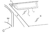
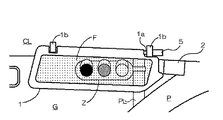
図1及び図2に例示するように、実施形態に係る投影装置Sにおいては、バックミラーBM及びフロント窓Gを有する車両Cの外を撮影し、その撮影結果に相当する画像データを出力するカメラ2が、車両Cの進行方向前方に向けて設置されている。より具体的にカメラ2は、フロント窓G内側の運転者側の上角部(ピラーPの脇)で、サンバイザ1が降ろされてもその前方が遮られない位置に配置されている。そしてカメラ2は、当該位置からフロント窓Gを透過して、少なくとも車両Cの前方を撮影すべく、その撮影方向が設定されている。このとき、サンバイザ1が降ろされたときに運転者から見て死角となる車両Cの外の領域がカメラ2の撮影範囲に少なくとも入るように、当該カメラ2の設置位置及び撮影方向が予め設定されている。
As illustrated in FIGS. 1 and 2, in the projection apparatus S according to the embodiment, a camera that captures the outside of the vehicle C having the rearview mirror BM and the front window G and outputs image data corresponding to the imaging result. 2 is installed toward the front in the traveling direction of the vehicle C. More specifically, the
ここでカメラ2は、例えば、CCD(Charge Coupled Device)カメラやCMOS(Complementary Metal Oxide Semiconductor)カメラ等のデジタルカメラにより構成される。そしてカメラ2は、例えば予め設定された時間間隔で連続的に、その撮影範囲に存在する人又は物を撮影し、当該撮像した結果に相当する画像データを生成して後述する逆光補正部に出力する。このとき、カメラ2の撮影範囲に存在する人又は物の例としては、通行者や、降ろされたサンバイザ1により死角となる車両Cの外の範囲(例えば、運転席から見て右前方上方の範囲)に存在する信号機等が挙げられる。
Here, the
一方、実施形態に係る投影装置は、詳細については後述するが、カメラ2により撮影した画像を、後述する逆光補正部や画像処理部等による画像処理を施した後に、後述するプロジェクタを介してサンバイザ1の室内側の投影面Fに投影する。具体的にこの投影面Fには、運転者の視点位置から見てサンバイザ1により死角となる領域にある車両Cの外方の景色の画像が投影/表示される。図2に示す例では、当該死角となる領域に存在し且つカメラ2により撮影された信号機の画像Zであって、地面に対して当該信号機を支持する支柱PLの画像を含む画像Zが投影面Fに投影されている。なお図2においては、投影面Fに投影された画像Zをドットハッチングにより示している。このとき、運転者がフロント窓G越しに実際に視認できる支柱PLの下方の部分と、カメラ2により撮影された画像Z内のその支柱の上部の部分とが連続するように、当該画像Zが投影/表示されている。
On the other hand, the projection apparatus according to the embodiment will be described in detail later. However, after the image captured by the
更に上記サンバイザ1は図2に例示するように、従来のサンバイザのごとく、フロント窓Gの上縁部と平行に設けられた回動軸1aを有し、その回動軸1aが室内の天井CLに固定された軸受部1bにより軸受された状態で、設けられている。そして、この構成によりサンバイザ1は、運転者が手動で、上記回動軸1a周りに回動可能な状態で、サンバイザ1の運転者に対する角度を変化させ、更に任意の当該角度でサンバイザ1自体を保持可能に、構成されている。なお以下の説明において、上記サンバイザ1の運転者に対する角度を、単に「サンバイザ1の角度」と称する。そしてサンバイザ1の角度は、サンバイザ1の収納状態(例えば水平状態)からの回動の角度を示しており、サンバイザ1が運転者により任意に姿勢が変化されることから、逐次異なるものとなる。
Further, as illustrated in FIG. 2, the
一方図2に例示するように、サンバイザ1の角度を検出する角度センサ5が、サンバイザ1の回動軸1aを軸受する軸受部1bに設けられている。この角度センサ5は、従来と同様の例えばポテンショメータやエンコーダ等により、基準面(例えば収納状態のサンバイザ1が含まれる水平面)に対する上記回動軸1aの回動の角度をサンバイザ1の角度として検出し、後述する画像処理部に出力する。
On the other hand, as illustrated in FIG. 2, an
なお、図1及び図2に示す構成において、サンバイザ1が本発明に係る「遮蔽物」の一例に相当し、カメラ2が本発明に係る「撮影手段」の一例に相当し、角度センサ5が本発明に係る「検出手段」の一例に相当する。
In the configuration shown in FIGS. 1 and 2, the
次に、実施形態に係る投影装置全体の構成及び動作について、図1乃至図4を用いて説明する。 Next, the configuration and operation of the entire projection apparatus according to the embodiment will be described with reference to FIGS.
図3に示すように、上記カメラ2及び角度センサ5を含む実施形態に係る投影装置Sは、当該カメラ2及び角度センサ5に加えて、車両Cの天井CLに備えられた上記プロジェクタ3と、視点位置センサ4と、CPU、RAM(Random Access Memory)及びROM(Read Only Memory)等からなる上記画像処理部10と、上記逆光補正部11と、視点位置検出部12と、により構成されている。このとき、プロジェクタ3が本発明に係る「投影手段」の一例に相当し、視点位置センサ4が本発明に係る「位置検出手段」の一例に相当し、画像処理部10が本発明に係る「補正手段」の一例及び「投影制御手段」の一例にそれぞれ相当し、逆光補正部11が本発明に係る「逆光補正手段」の一例に相当する。
As shown in FIG. 3, the projection device S according to the embodiment including the
この構成において視点位置センサ4は、例えばボンネットBと略同じ高さの車室内に設置されたカメラ等によって運転者Dの顔画像を撮影し、その撮影結果を視点位置検出部12に出力する。そして視点位置検出部12は、当該撮影結果(顔画像)の内容を解析し、運転者Dの視点位置及び視線の方向を検出し、それぞれの検出結果を視点位置データとして画像処理部10に出力する。
In this configuration, the viewpoint position sensor 4 captures the face image of the driver D by using a camera or the like installed in a passenger compartment that is substantially the same height as the bonnet B, and outputs the captured result to the viewpoint
ここで、車両Cにサンバイザ1と視点位置センサ4が備えられた時点で、サンバイザ1の位置から視点位置センサ4の位置に向かう空間的なベクトル(以下、当該空間的なベクトルを「第1ベクトル」と称する)は予め判明している。よってこの第1ベクトルを示すデータは、画像処理10内に予め不揮発性に記憶させておくことが可能である。一方、視点位置センサ4の位置から運転者Dの目の位置までの空間的なベクトル(以下、当該空間的なベクトルを第2ベクトルと称する)は、視点位置センサ4の位置から、当該視点位置センサ4により撮影された顔画像内の目の位置に向かうベクトルを視点位置検出部12において算出することにより求められる。よってこれらにより視点位置検出部12は、上記第1ベクトルと上記第2ベクトルを加算していられる空間的なベクトルの逆向きのベクトルとして、上記視線に相当する視線ベクトル、及び、当該視線ベクトルとサンバイザ1が交わる点としての運転者Dの上記視点位置を検出する。
Here, when the vehicle C is equipped with the
一方角度センサ5は、図3に例示するように回動するサンバイザ1の角度を検出し、その検出結果を角度データとして画像処理部10に出力する。このサンバイザ1の角度は上述したように、その収納状態からの回動の角度である。
On the other hand, the
他方カメラ2は、その撮影範囲に相当する上記画像データを生成して逆光補正部11に出力する。これにより逆光補正部11は、当該画像データに対して例えば従来と同様の方法による逆光補正処理を施して、画像処理部10に出力する。
On the other hand, the
そして画像処理部10は、上記視点位置データ、上記角度データ及び上記逆光補正部11からの画像データに基づき、サンバイザ1の室内側の投影面F(図1及び図2参照)に投影される画像Zに相当する投影画像データを生成してプロジェクタ3に出力する。そしてプロジェクタ3は、上記投影画像データに相当する投影光Lを投影面Fに向けて出射し、上記画像Zを当該投影面F上に投影/表示する(図2参照)。
Then, the
次に、画像処理部10を中心として実行される、実施形態に係る投影処理について、より具体的に図4を用いて説明する。なお実施形態に係る投影処理は、上記視点位置データ、上記画像データ及び上記角度データが入力される画像処理部10を中心として実行される。
Next, the projection processing according to the embodiment, which is executed centering on the
即ち、図4に示す実施形態に係る投影処理は、例えば投影装置Sが備えられている車両CのACC(Accessory)スイッチがオンとされることに伴って開始される。そして、実施形態に係る表示処理が開示されると、図4に示すように画像処理部10は、その時点での上記視点位置データ及び角度データを、視点位置センサ4及び角度センサ5からそれぞれ取得する(ステップS1)。
That is, the projection processing according to the embodiment shown in FIG. 4 is started when, for example, the ACC (Accessory) switch of the vehicle C provided with the projection device S is turned on. When the display processing according to the embodiment is disclosed, as illustrated in FIG. 4, the
次に画像処理部10は、当該取得した角度データに基づいて、サンバイザ1が現在降ろされている状態か否か(即ち、使用状態か否か)を判定する(ステップS2)。このステップS2の判定は、サンバイザ1が降ろされることにより、運転者Dに車両外の死角となる領域が発生しているか否かの判定でもある。ステップS2の判定において、サンバイザ1が現在降ろされている状態でない場合(ステップS2:NO)、サンバイザ1が収納状態(上げられた状態)であって実施形態に係る投影処理ができない状態であるため、画像処理部10は後述するステップS7に移行する。一方ステップS2の判定において、サンバイザ1が現在降ろされている場合(ステップS2:YES)、画像処理部10は次に、その時点で逆光補正部11により上記逆光補正処理が施されている上記画像データを取得する(ステップS3)。次に画像処理部10は、上記視点位置データを用いて視点位置検出部12により検出された上記視線ベクトル及び運転者Dの上記視点位置に基づき、当該取得した画像データの中から、サンバイザ1越しの当該視線ベクトル上となる領域(即ち、現在死角となっている車両外の領域)に相当する画像を、例えば従来と同様の方法により切り出す(ステップS4)。このとき画像処理部10は、サンバイザ1の室内側の投影面Fの大きさに対応させて、必要な大きさの画像を切り出す。次に画像処理部10は、上記角度データに基づき、当該切り出した画像に対していわゆる台形補正処理を施す(ステップS5)。このステップS5として画像処理部10は、上記角度データにより示されるサンバイザ1の運転者Dに対する角度(換言すれば、サンバイザ1の運転者Dに対する「斜め具合」)に基づき、運転者Dが投影面F上の投影画像を視認した際にあたかもサンバイザ1を透過しているかの如く視認できるように、上記切り出した画像を台形補正する。
Next, the
その後画像処理部10は、台形補正された画像に対応する投影画像データをプロジェクタ3に出力する。これによりプロジェクタ3は、その時点で降ろされている(上記ステップS2:YES参照)サンバイザ1の投影面Fに向けて、上記投影画像データに相当する投影光Lを出射することで、当該投影画像データに対応する画像Zを投影面Fに表示させる(ステップS6。図2参照)。
Thereafter, the
その後画像処理部10は、例えば車両が停止して上記ACCスイッチがオフとされる等により、実施形態に係る投影処理を終了するか否かを判定する(ステップS7)。ステップS7の判定において、実施形態に係る投影処理を終了しない場合(ステップS7:NO)、画像処理部10は上記ステップS1に戻って上述してきた投影処理を繰り返す。一方、ステップS7の判定において実施形態に係る投影処理を終了する場合(ステップS7:YES)、画像処理部10はそのまま当該投影処理を終了する。
Thereafter, the
以上説明したように、実施形態に係る投影処理によれば、車両C外の死角となる領域を撮影して得られた画像データを補正した画像Zが投影されるサンバイザ1の状態を検出し、その状態に基づいて画像データを補正してサンバイザ1に投影させる。よって、画像Zが投影されるサンバイザ1の状態に基づいて補正された画像Zを、プロジェクタ3によりサンバイザ1に光学的に投影させるので、サンバイザ1自体としての元来の機能(例えば、鏡やカードホルダ等を装着可能な機能)を損なうことなく、サンバイザ1により実際には視認できなくなる領域を運転者Dに視認させることができる。
As described above, according to the projection processing according to the embodiment, the state of the
また遮蔽物としてのサンバイザ1が、運転者Dの視線の方向と交差する方向の回動軸1aを中心として回動可能に備えられており、運転者Dとの関係におけるサンバイザ1の回動の角度を示す角度データに基づく台形補正処理が、カメラ2からの画像データに施される。よって、サンバイザ1の角度に基づく台形補正処理が施されることで、実際には視認できなくなる領域を運転者Dに鮮明に視認させることができる。
Further, a
更に、上記角度データと上記視点位置データとに基づいて台形補正処理を施すので、実際には視認できなくなる領域をより鮮明に運転者Dに視認させることができる。 Furthermore, since the trapezoidal correction process is performed based on the angle data and the viewpoint position data, it is possible for the driver D to visually recognize a region that cannot actually be visually recognized.
更にまた、カメラ2により得られた画像データに対して逆光補正処理を施すので、サンバイザ1を使用して日光を遮る必要がある場合でも、サンバイザ1により実際には視認できなくなる領域を、日光の影響を低減して運転者Dに明確に視認させることができる。
Furthermore, since the backlight correction process is performed on the image data obtained by the
(II)変形形態
次に、本発明に係る変形形態について、図5乃至図7を用いて説明する。なお、図5は第1変形形態に係る投影装置の一部の構成を示す側面図であり、図6は第2変形形態に係る投影装置の構成を示す外観図であり、図7は第3変形形態に係る投影装置の構成を示す側視外観図である。ここで、以下の各変形形態に係る投影装置の構成は、基本的には実施形態に係る投影装置Sの構成と同一であるので、以下の説明では、実施形態に係る投影装置Sの部材番号を引用して、各変形形態に係る構成や動作を説明する。
(II) Modified Embodiment Next, a modified embodiment according to the present invention will be described with reference to FIGS. FIG. 5 is a side view showing a configuration of a part of the projection apparatus according to the first modification, FIG. 6 is an external view showing the configuration of the projection apparatus according to the second modification, and FIG. It is a side view external view which shows the structure of the projection apparatus which concerns on a deformation | transformation form. Here, the configuration of the projection apparatus according to each of the following modifications is basically the same as the configuration of the projection apparatus S according to the embodiment. Therefore, in the following description, the member number of the projection apparatus S according to the embodiment The configuration and operation according to each modified embodiment will be described with reference to.
(i)第1変形形態
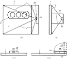
初めに第1変形形態として、上述した実施形態に係る投影装置Sではサンバイザ1の室内側の投影面Fに直接画像Zを投影させることとしたが、これ以外に図5に示すように、画像Zの投影専用のスクリーン20を、運転者Dに対して室内側に且つ回動可能にサンバイザ1に備えさせ、このスクリーン20にプロジェクタ3からの画像Zを投影させるように構成してもよい。この場合、上記角度センサ5は、スクリーン20の回動の角度を検出して上記角度データを画像処理部10に出力することになる。この第1変形形態に係る構成によれば、画像Zが投影されるスクリーン20がサンバイザ1に備えられており、スクリーン20の運転者Dとの関係における角度が検出され、上記画像Zがスクリーン20に投影される。よって、専用のスクリーン20を用いることで、死角となる領域をより鮮明に運転者Dに視認させることができる。
(I) First Modification As a first modification , the projection apparatus S according to the embodiment described above directly projects the image Z on the projection surface F on the indoor side of the
(ii)第2変形形態
次に第2変形形態として、上述した実施形態では、投影用のプロジェクタ3を車両Cの天井CLに設ける構成としたが、これ以外に、プロジェクタ自体をサンバイザ1に備えさせてもよい。
(Ii) Second Modification As a second modification, in the above-described embodiment, the projector 3 for projection is provided on the ceiling CL of the vehicle C. In addition, the projector itself is provided in the
即ち図6(a)に投影時の正面図(運転者D側から見た正面図)を示し、図6(b)に投影時の側面図を示すように、サンバイザ1の室内側における投影面Fの脇に、例えば単焦点型のレンズ26を備えるプロジェクタ25を設け、このプロジェクタ25から図6(a)及び図6(b)に例示するように投影光Lを照射して、画像Zを投影面F上に表示するように構成することができる。この第2変形形態の構成では、プロジェクタ25のレンズ26の位置と、それに対する投影面Fの位置と、が、画像Zの投影時において常に一定の関係となるので、より鮮明に画像Zを投影面Fに投影することができる。
That is, FIG. 6A shows a front view at the time of projection (front view seen from the driver D side), and FIG. 6B shows a side view at the time of projection, as shown in FIG. A
また、図6に例示するプロジェクタ25は、非使用時においては、図6(c)及び図6(d)に例示するように、例えばヒンジ27によりレンズ26を内側にして折り畳めるように構成するのが好ましい。この場合のヒンジ27が本発明に係る「格納手段」の一例に相当する。このような構造とすることにより、サンバイザ1を上げて収納する場合でも、プロジェクタ25がその障害になることもない。なお第2変形形態に係る投影装置の他の構成(例えば角度センサ5の位置等)は、基本的には実施形態に係る投影装置Sと同様でよい。
Further, when not in use, the
この第2変形形態に係る構成によれば、プロジェクタ25がサンバイザ1に備えられており、サンバイザ1の格納に伴ってヒンジ27によりプロジェクタ25も格納されるので、サンバイザ1とプロジェクタ25とを一体化することで、死角となる領域をより鮮明に運転者Dに視認させることができる。
According to the configuration according to the second modification, the
(iii)第3変形形態
次に第3変形形態について説明する。以下に説明する第3変形形態は、サンバイザ1が降ろされているか否かの判定(図4ステップS2参照)に関連する変形形態である。
(Iii) Third Modification Next, a third modification will be described. The third modification described below is a modification related to the determination of whether or not the
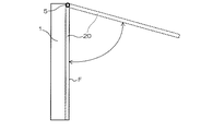
即ち上述したように、サンバイザ1が降ろされているか否かの判定は、実施形態に係る投影処理において投影面Fに実際に画像Zを投影するか否かの判定でもある。そこで、サンバイザ1が降ろされているか否かの判定として、例えば図7(a)に示すように、運転者Dに死角を感じさせる上記サンバイザ1の角度の範囲を予め設定し、その角度範囲以上にサンバイザ1が降ろされた場合に(図4ステップS2:YES参照)、図4のステップS3に移行するように構成してもよい。この場合、上記死角を感じさせるサンバイザ1の角度の範囲として例えば図7(a)に示す角度範囲βが予め設定されているとすると、当該角度範囲β内の角度にサンバイザ1が降ろされた場合(図4ステップS2:YES参照)には、その時の角度に応じた画像Zの投影を行う(開始する)ように構成するのが好適である。これに対し、当該角度範囲βに至らない角度範囲α内の角度にしかサンバイザ1が降ろされていない場合(図4ステップS2:NO参照)には、画像Zの投影を行わない(開始しない)ように構成するのが好適である。このとき、上記角度範囲α及び角度範囲βそれぞれの具体的な値は、例えば経験的又は実験的に予め設定するか、或いは、運転者Dにより設定又は変更が可能に構成すればよい。
That is, as described above, whether or not the
また、実施形態に係る投影装置Sにおける視点位置センサ4及び視点位置検出部12により、運転者Dの視点位置と共にその目の高さ(鉛直方向の高さ)を検出し、その高さに基づいて図4のステップS2の判定を行うように構成することもできる。この場合、例えば座高や身長に起因して、図7(b)に例示する視野EA1を有する運転者D1の目の高さと、図7(c)に例示する視野EA2を有する運転者D2の眼の高さと、が異なっているとき、視点位置センサ4及び視点位置検出部12によりそれぞれの目の高さを検出する。そして、図7(b)に例示する運転者D1の目の高さの場合は、角度γを有するサンバイザ1により死角となる領域が発生しているため(図4ステップS2:YES参照)、当該角度γに応じた画像Zの投影を行う(開始する)ように構成するのが好適である。これに対し、同じサンバイザ1の角度γであっても、図7(c)に例示する運転者D2の目の高さの場合は、サンバイザ1により死角となる領域が発生していないため(図4ステップS2:NO参照)、画像Zの投影は行なわない(開始しない)ように構成するのが好適である。これら図7(b)及び図7(c)に例示する場合、一般的には、座高又は背が低い運転者Dほど、画像Zの投影を行わないサンバイザ1の角度が大きくなることになる。
Further, the eye position (vertical height) is detected together with the viewpoint position of the driver D by the viewpoint position sensor 4 and the viewpoint
(iv)その他の変形形態
その他の変形形態として、運転者Dの視線だけでなく、例えば助手席に座る同乗者の視野がその前方のサンバイザにより遮られる場合において、そのサンバイザ越しに同乗者が見えるはずの画像をそのサンバイザの内側に投影する場合に、本発明を適用することもできる。
(Iv) Other Modifications As another modification, not only the driver's line of sight but also, for example, when the passenger's field of view sitting in the passenger seat is obstructed by the sun visor in front of it, the passenger can be seen through the sun visor. The present invention can also be applied to a case where a supposed image is projected inside the sun visor.
また、運転者Dが運転する車両は、実施形態又は各変形形態に係る車両C以外にも、例えばフード付の二輪車等であってもよい。 Further, the vehicle driven by the driver D may be, for example, a two-wheeled vehicle with a hood in addition to the vehicle C according to the embodiment or each modification.
更に、図4に示すフローチャートに対応するプログラムを、例えば光ディスク又はハードディスク等の記録媒体に記録しておき、或いはインターネット等のネットワークを介して取得して記録しておき、当該プログラムを例えば汎用のマイクロコンピュータ等で読み出して実行することにより、当該マイクロコンピュータ等を実施形態及び各変形形態に係る画像処理部10として機能させることもできる。
Further, a program corresponding to the flowchart shown in FIG. 4 is recorded on a recording medium such as an optical disk or a hard disk, or acquired and recorded via a network such as the Internet, and the program is recorded on, for example, a general-purpose micro computer. By reading and executing with a computer or the like, the microcomputer or the like can be caused to function as the
以上それぞれ説明したように、本発明は投影装置の分野に利用することが可能であり、特に、運転者等の人から見て死角となる領域に存在するものを視認可能とする投影装置の分野に適用すれば特に顕著な効果が得られる。 As described above, the present invention can be used in the field of projection devices, and in particular, the field of projection devices that can visually recognize what is in a blind spot as viewed from a person such as a driver. When applied to, particularly remarkable effects can be obtained.
1 サンバイザ
1a 回動軸
1b 軸受部
2 カメラ
3、25 プロジェクタ
4 視点位置センサ
5 角度センサ
10 画像処理部
11 逆光補正部
12 視点位置検出部
20 スクリーン
26 レンズ
27 ヒンジ
S 投影装置
BM バックミラー
G フロント窓
C 車両
P ピラー
F 投影面
Z 画像
CL 天井
PL 支柱
D、D1、D2 運転者
α、β 角度範囲
EA1、EA2 視野
γ 角度
DESCRIPTION OF
Claims (9)
前記検出された状態を示す状態情報に基づいて、前記撮影情報を補正して前記補正撮影情報を生成する補正手段と、
前記生成された補正撮影情報に相当する前記投影画像を、投影手段を用いて前記遮蔽物に投影させる投影制御手段と、
を備えることを特徴とする投影装置。 Photographing obtained by photographing a blind spot area outside the vehicle, which is a blind spot of the passenger, by a movable shield provided inside the vehicle, which blocks the field of view of the passenger facing outside the vehicle. Detecting means for detecting a state in relation to the occupant of the shielding object on which the projection image corresponding to the corrected photographing information obtained by correcting the information is projected;
Correction means for correcting the shooting information to generate the corrected shooting information based on the state information indicating the detected state;
Projection control means for projecting the projection image corresponding to the generated corrected photographing information onto the shield using a projection means;
A projection apparatus comprising:
前記遮蔽物は、前記死角領域に向いた前記搭乗者の視線の方向と交差する方向の軸を中心として回動可能に前記車両に備えられており、
前記検出手段は、前記搭乗者との関係における前記遮蔽物の前記回動の角度を前記状態として検出し、
前記補正手段は、前記検出された角度を示す前記状態情報に基づき、前記撮影情報に対して台形補正処理を施して前記補正撮影情報を生成することを特徴とする投影装置。 The projection device according to claim 1,
The shield is provided in the vehicle so as to be rotatable about an axis in a direction intersecting with the direction of the line of sight of the occupant facing the blind spot area,
The detecting means detects the rotation angle of the shield in the relationship with the passenger as the state;
The projection device according to claim 1, wherein the correction means generates the corrected shooting information by performing a keystone correction process on the shooting information based on the state information indicating the detected angle.
前記搭乗者の視点位置を検出する位置検出手段を更に備え、
前記補正手段は、前記状態情報と、前記検出された視点位置を示す視点位置情報と、に基づき、前記撮影情報を補正して前記補正撮影情報を生成することを特徴とする投影装置。 The projection device according to claim 1 or 2,
Further comprising position detecting means for detecting the viewpoint position of the passenger,
The projection apparatus, wherein the correction unit corrects the shooting information based on the state information and viewpoint position information indicating the detected viewpoint position to generate the corrected shooting information.
前記遮蔽物が前記車両に備えられたサンバイザであり、
前記撮影情報に対して逆光補正処理を施して前記補正手段に出力する逆光補正手段を更に備えることを特徴とする投影装置。 In the projection device according to any one of claims 1 to 3,
The shield is a sun visor provided in the vehicle;
A projection apparatus, further comprising a backlight correction unit that performs backlight correction processing on the photographing information and outputs the processed information to the correction unit.
前記遮蔽物に備えられ且つ前記投影画像が投影されるスクリーンを備え、
前記検出手段は、前記スクリーンの前記搭乗者との関係における前記状態を検出し、
前記投影制御手段は、前記生成された補正撮影情報に相当する前記投影画像を前記スクリーンの投影面に投影させることを特徴とする投影装置。 In the projection device according to any one of claims 1 to 4,
A screen provided on the shield and onto which the projection image is projected;
The detecting means detects the state of the screen in relation to the passenger;
The projection control unit projects the projection image corresponding to the generated corrected photographing information onto a projection surface of the screen.
前記投影手段は前記遮蔽物に備えられており、
前記遮蔽物の格納に伴って前記投影手段を格納する格納手段を備えることを特徴とする投影装置。 In the projection device according to any one of claims 1 to 5,
The projection means is provided in the shield;
A projection apparatus comprising storage means for storing the projection means as the shielding object is stored.
当該遮蔽物により前記搭乗者の死角となる前記車両外の死角領域を撮影手段により撮影して得られた撮影情報に対応する投影画像が投影手段により投影される投影面を備え、
当該投影画像が、前記搭乗者との関係における前記遮蔽物の状態に基づいて前記撮影情報を補正した補正撮影情報に相当する前記投影画像であることを特徴とする遮蔽物。 In a movable shield that shields a passenger's field of view toward the outside of the vehicle and is provided in the vehicle,
A projection surface on which a projection image corresponding to photographing information obtained by photographing a blind spot area outside the vehicle, which is a blind spot of the occupant by the shield, is photographed by the photographing unit;
The said projection image is the said projection image corresponded to the correction | amendment imaging | photography information which corrected the said imaging | photography information based on the state of the said shielding object in the relationship with the said passenger.
車両の外に向けた搭乗者の視野を遮り且つ前記車両内に備えられた可動式の遮蔽物により前記搭乗者の死角となる前記車両外の死角領域を撮影手段により撮影して得られた撮影情報を補正した補正撮影情報に相当する投影画像が投影される前記遮蔽物の、前記搭乗者との関係における状態を検出する検出工程と、
前記検出された状態を示す状態情報に基づいて、前記撮影情報を補正して前記補正撮影情報を生成する補正工程と、
前記生成された補正撮影情報に相当する前記投影画像を、投影手段を用いて前記遮蔽物に投影させる投影制御工程と、
を含むことを特徴とする投影方法。 In a projection method performed in a vehicle,
Photographing obtained by photographing a blind spot area outside the vehicle, which is a blind spot of the passenger, by a movable shield provided inside the vehicle, which blocks the field of view of the passenger facing outside the vehicle. A detection step of detecting a state in relation to the occupant of the shielding object on which the projection image corresponding to the corrected photographing information obtained by correcting the information is projected;
A correction step of correcting the shooting information to generate the corrected shooting information based on the state information indicating the detected state;
A projection control step of projecting the projection image corresponding to the generated corrected photographing information onto the shielding object using a projection unit;
A projection method comprising:
前記車両の外に向けた搭乗者の視野を遮り且つ前記車両内に備えられた可動式の遮蔽物により前記搭乗者の死角となる前記車両外の死角領域を撮影手段により撮影して得られた撮影情報を補正した補正撮影情報に相当する投影画像が投影される前記遮蔽物の、前記搭乗者との関係における状態を検出する検出手段、
前記検出された状態を示す状態情報に基づいて、前記撮影情報を補正して前記補正撮影情報を生成する補正手段、及び、
前記生成された補正撮影情報に相当する前記投影画像を、投影手段を用いて前記遮蔽物に投影させる投影制御手段、
として機能させることを特徴とする投影用プログラム。 The computer installed in the vehicle
Obtained by photographing a blind spot area outside the vehicle, which is a blind spot of the passenger, with a movable shield provided inside the vehicle, which blocks the field of view of the passenger facing the outside of the vehicle. Detecting means for detecting a state of the shielding object on which the projection image corresponding to the corrected photographing information obtained by correcting the photographing information is projected in relation to the passenger;
Based on state information indicating the detected state, correction means for correcting the shooting information and generating the corrected shooting information; and
Projection control means for projecting the projection image corresponding to the generated corrected photographing information onto the shielding object using a projection means;
Projecting program characterized by functioning as
Priority Applications (1)
| Application Number | Priority Date | Filing Date | Title |
|---|---|---|---|
| JP2016064432A JP2017181588A (en) | 2016-03-28 | 2016-03-28 | Projection device, shield, projection method and projection program |
Applications Claiming Priority (1)
| Application Number | Priority Date | Filing Date | Title |
|---|---|---|---|
| JP2016064432A JP2017181588A (en) | 2016-03-28 | 2016-03-28 | Projection device, shield, projection method and projection program |
Publications (1)
| Publication Number | Publication Date |
|---|---|
| JP2017181588A true JP2017181588A (en) | 2017-10-05 |
Family
ID=60006907
Family Applications (1)
| Application Number | Title | Priority Date | Filing Date |
|---|---|---|---|
| JP2016064432A Pending JP2017181588A (en) | 2016-03-28 | 2016-03-28 | Projection device, shield, projection method and projection program |
Country Status (1)
| Country | Link |
|---|---|
| JP (1) | JP2017181588A (en) |
Cited By (3)
| Publication number | Priority date | Publication date | Assignee | Title |
|---|---|---|---|---|
| CN113223312A (en) * | 2021-04-29 | 2021-08-06 | 重庆长安汽车股份有限公司 | Camera blindness prediction method and device based on map and storage medium |
| JP2021164007A (en) * | 2020-03-30 | 2021-10-11 | パナソニックIpマネジメント株式会社 | Video display system, video display method, and vehicle |
| CN114043861A (en) * | 2021-11-01 | 2022-02-15 | 安徽安健汽车天窗科技有限公司 | Projection type automobile skylight |
Citations (11)
| Publication number | Priority date | Publication date | Assignee | Title |
|---|---|---|---|---|
| JP2006260011A (en) * | 2005-03-16 | 2006-09-28 | Denso Corp | Display device for vehicle |
| JP2008009654A (en) * | 2006-06-28 | 2008-01-17 | Toyota Motor Corp | Display device for vehicle |
| JP2009006893A (en) * | 2007-06-28 | 2009-01-15 | Aisin Aw Co Ltd | Drive assisting device and computer program |
| WO2009040975A1 (en) * | 2007-09-25 | 2009-04-02 | Sharp Kabushiki Kaisha | Screen |
| JP2012056480A (en) * | 2010-09-09 | 2012-03-22 | Ricoh Co Ltd | Vehicle rear view apparatus |
| US20140168608A1 (en) * | 2012-12-18 | 2014-06-19 | Volvo Car Corporation | Vehicle adaptation to automatic driver independent control mode |
| JP2015012559A (en) * | 2013-07-02 | 2015-01-19 | 株式会社デンソー | Projection type display device |
| JP2015027852A (en) * | 2013-07-30 | 2015-02-12 | トヨタ自動車株式会社 | Driving support equipment |
| JP2015047885A (en) * | 2013-08-29 | 2015-03-16 | トヨタ車体株式会社 | On-vehicle interactive system |
| JP2015192203A (en) * | 2014-03-27 | 2015-11-02 | 日立マクセル株式会社 | Video processing apparatus and projector using the same |
| JP2017034615A (en) * | 2015-08-06 | 2017-02-09 | 株式会社Jvcケンウッド | Display device for vehicle and display method |
-
2016
- 2016-03-28 JP JP2016064432A patent/JP2017181588A/en active Pending
Patent Citations (11)
| Publication number | Priority date | Publication date | Assignee | Title |
|---|---|---|---|---|
| JP2006260011A (en) * | 2005-03-16 | 2006-09-28 | Denso Corp | Display device for vehicle |
| JP2008009654A (en) * | 2006-06-28 | 2008-01-17 | Toyota Motor Corp | Display device for vehicle |
| JP2009006893A (en) * | 2007-06-28 | 2009-01-15 | Aisin Aw Co Ltd | Drive assisting device and computer program |
| WO2009040975A1 (en) * | 2007-09-25 | 2009-04-02 | Sharp Kabushiki Kaisha | Screen |
| JP2012056480A (en) * | 2010-09-09 | 2012-03-22 | Ricoh Co Ltd | Vehicle rear view apparatus |
| US20140168608A1 (en) * | 2012-12-18 | 2014-06-19 | Volvo Car Corporation | Vehicle adaptation to automatic driver independent control mode |
| JP2015012559A (en) * | 2013-07-02 | 2015-01-19 | 株式会社デンソー | Projection type display device |
| JP2015027852A (en) * | 2013-07-30 | 2015-02-12 | トヨタ自動車株式会社 | Driving support equipment |
| JP2015047885A (en) * | 2013-08-29 | 2015-03-16 | トヨタ車体株式会社 | On-vehicle interactive system |
| JP2015192203A (en) * | 2014-03-27 | 2015-11-02 | 日立マクセル株式会社 | Video processing apparatus and projector using the same |
| JP2017034615A (en) * | 2015-08-06 | 2017-02-09 | 株式会社Jvcケンウッド | Display device for vehicle and display method |
Cited By (5)
| Publication number | Priority date | Publication date | Assignee | Title |
|---|---|---|---|---|
| JP2021164007A (en) * | 2020-03-30 | 2021-10-11 | パナソニックIpマネジメント株式会社 | Video display system, video display method, and vehicle |
| JP7426607B2 (en) | 2020-03-30 | 2024-02-02 | パナソニックIpマネジメント株式会社 | Video display system, video display method, and vehicle |
| CN113223312A (en) * | 2021-04-29 | 2021-08-06 | 重庆长安汽车股份有限公司 | Camera blindness prediction method and device based on map and storage medium |
| CN114043861A (en) * | 2021-11-01 | 2022-02-15 | 安徽安健汽车天窗科技有限公司 | Projection type automobile skylight |
| CN114043861B (en) * | 2021-11-01 | 2023-05-26 | 安徽安健汽车天窗科技有限公司 | Projection type automobile skylight |
Similar Documents
| Publication | Publication Date | Title |
|---|---|---|
| US11336839B2 (en) | Image display apparatus | |
| JP5222597B2 (en) | Image processing apparatus and method, driving support system, and vehicle | |
| US7629946B2 (en) | Display apparatus | |
| US11244173B2 (en) | Image display apparatus | |
| JP5093611B2 (en) | Vehicle periphery confirmation device | |
| US20160125631A1 (en) | Apparatus for dynamically controlling hud (head-up display) information display position | |
| JP2005184225A (en) | Vehicular display | |
| JP2004064131A (en) | Display for vehicle | |
| JP2011234095A (en) | Visual recognition support device for vehicle | |
| JP2017181588A (en) | Projection device, shield, projection method and projection program | |
| JP2006044596A (en) | Display device for vehicle | |
| JP4552636B2 (en) | Driver monitor system and processing method thereof | |
| JP2013166414A (en) | Display device for vehicle rear seat and display device for vehicle | |
| JP2005204132A (en) | Drive support apparatus | |
| KR20170126149A (en) | System for Providing Front Pillar View for a Vehicle | |
| JP2010179817A (en) | Anti-dazzling device for vehicle | |
| JP2009035162A (en) | Rear view monitoring device | |
| JP2009288498A (en) | Projector | |
| JP6845988B2 (en) | Head-up display | |
| JP5797155B2 (en) | Driving support display device for rear window | |
| JP2016032978A (en) | Vehicle periphery photographing device | |
| JP6481445B2 (en) | Head-up display | |
| JP2017181586A (en) | Display device, display method and display device program | |
| JP2015085879A (en) | Vehicular display device | |
| JP2006137209A (en) | Anti-glare device for vehicle |
Legal Events
| Date | Code | Title | Description |
|---|---|---|---|
| A621 | Written request for application examination |
Free format text: JAPANESE INTERMEDIATE CODE: A621 Effective date: 20190130 |
|
| A977 | Report on retrieval |
Free format text: JAPANESE INTERMEDIATE CODE: A971007 Effective date: 20191118 |
|
| A131 | Notification of reasons for refusal |
Free format text: JAPANESE INTERMEDIATE CODE: A131 Effective date: 20191126 |
|
| A02 | Decision of refusal |
Free format text: JAPANESE INTERMEDIATE CODE: A02 Effective date: 20200527 |