JP5259157B2 - Laser microscope - Google Patents
Laser microscope Download PDFInfo
- Publication number
- JP5259157B2 JP5259157B2 JP2007292413A JP2007292413A JP5259157B2 JP 5259157 B2 JP5259157 B2 JP 5259157B2 JP 2007292413 A JP2007292413 A JP 2007292413A JP 2007292413 A JP2007292413 A JP 2007292413A JP 5259157 B2 JP5259157 B2 JP 5259157B2
- Authority
- JP
- Japan
- Prior art keywords
- laser light
- pulse laser
- ultrashort pulse
- optical system
- polarization
- Prior art date
- Legal status (The legal status is an assumption and is not a legal conclusion. Google has not performed a legal analysis and makes no representation as to the accuracy of the status listed.)
- Expired - Fee Related
Links
Images

Classifications
-
- G—PHYSICS
- G02—OPTICS
- G02B—OPTICAL ELEMENTS, SYSTEMS OR APPARATUS
- G02B21/00—Microscopes
- G02B21/06—Means for illuminating specimens
-
- G—PHYSICS
- G02—OPTICS
- G02B—OPTICAL ELEMENTS, SYSTEMS OR APPARATUS
- G02B21/00—Microscopes
- G02B21/0004—Microscopes specially adapted for specific applications
- G02B21/002—Scanning microscopes
- G02B21/0024—Confocal scanning microscopes (CSOMs) or confocal "macroscopes"; Accessories which are not restricted to use with CSOMs, e.g. sample holders
- G02B21/0032—Optical details of illumination, e.g. light-sources, pinholes, beam splitters, slits, fibers
-
- G—PHYSICS
- G02—OPTICS
- G02B—OPTICAL ELEMENTS, SYSTEMS OR APPARATUS
- G02B21/00—Microscopes
- G02B21/0004—Microscopes specially adapted for specific applications
- G02B21/002—Scanning microscopes
- G02B21/0024—Confocal scanning microscopes (CSOMs) or confocal "macroscopes"; Accessories which are not restricted to use with CSOMs, e.g. sample holders
- G02B21/0052—Optical details of the image generation
- G02B21/0068—Optical details of the image generation arrangements using polarisation
-
- H—ELECTRICITY
- H01—ELECTRIC ELEMENTS
- H01S—DEVICES USING THE PROCESS OF LIGHT AMPLIFICATION BY STIMULATED EMISSION OF RADIATION [LASER] TO AMPLIFY OR GENERATE LIGHT; DEVICES USING STIMULATED EMISSION OF ELECTROMAGNETIC RADIATION IN WAVE RANGES OTHER THAN OPTICAL
- H01S5/00—Semiconductor lasers
- H01S5/005—Optical components external to the laser cavity, specially adapted therefor, e.g. for homogenisation or merging of the beams or for manipulating laser pulses, e.g. pulse shaping
- H01S5/0064—Anti-reflection components, e.g. optical isolators
Landscapes
- Physics & Mathematics (AREA)
- Chemical & Material Sciences (AREA)
- Analytical Chemistry (AREA)
- General Physics & Mathematics (AREA)
- Optics & Photonics (AREA)
- Microscoopes, Condenser (AREA)
Description
本発明は、光学装置およびレーザ顕微鏡に関するものである。 The present invention relates to an optical device and a laser microscope.
従来、レーザ光源から発せられ2光子励起顕微鏡に伝送されるレーザ光の一部が、その伝送途中において反射してレーザ光源に戻ることにより、レーザ光源のレーザ発振が不安定化して故障が誘発される不都合を防止するために、レーザ光源の後段に光アイソレータを配置する技術が知られている(例えば、非特許文献1参照。)。 Conventionally, a part of the laser light emitted from the laser light source and transmitted to the two-photon excitation microscope is reflected during the transmission and returned to the laser light source, so that the laser oscillation of the laser light source becomes unstable and a failure is induced. In order to prevent such inconvenience, a technique is known in which an optical isolator is arranged at the subsequent stage of a laser light source (see, for example, Non-Patent Document 1).
しかしながら、光アイソレータは、広い波長範囲にわたるレーザ光を伝送する場合の反射戻り光を防止するための手段としては、効率が悪い上に高価であるという不都合がある。また、磁力により作動するため、周囲に磁場を形成し、外部に悪影響を及ぼす不都合が考えられる。さらに、2光子励起顕微用のようにレーザ光源としてフェムト秒オーダのパルスレーザ光源を使用する場合には、光アイソレータにおける群速度遅延分散が大きく、その補償を十分に行う必要があるという問題もある。 However, the optical isolator has a disadvantage that it is inefficient and expensive as means for preventing reflected return light when transmitting laser light over a wide wavelength range. Moreover, since it operates by a magnetic force, the magnetic field is formed in the circumference | surroundings and the problem which has a bad influence on the exterior can be considered. Further, when a pulse laser light source of femtosecond order is used as a laser light source as in the case of two-photon excitation microscope, there is a problem that the group velocity delay dispersion in the optical isolator is large and the compensation thereof needs to be sufficiently performed. .
本発明は、上述した事情に鑑みてなされたものであって、安価で、外部に悪影響を及ぼすことなく、小さい群速度遅延分散で、効率的にレーザ光の反射戻り光がレーザ光源に戻らないように遮断することができ、後段の偏光依存素子に対して適正な偏光状態のレーザ光を入射させることができる光学装置およびレーザ顕微鏡を提供することを目的としている。 The present invention has been made in view of the above-described circumstances, and is inexpensive and does not adversely affect the outside, and with a small group velocity delay dispersion, the reflected return light of the laser light does not efficiently return to the laser light source. It is an object of the present invention to provide an optical device and a laser microscope that can be blocked in such a manner that a laser beam having an appropriate polarization state can be incident on a subsequent polarization-dependent element.
上記目的を達成するために、本発明は以下の手段を提供する。
本発明の参考例としての発明は、レーザ光源と、該レーザ光源から発せられたレーザ光を伝送する伝送光学系と、該伝送光学系により伝送されたレーザ光を入射させ、その入射偏光状態に応じて出射光特性が変化する偏光依存素子とを備え、前記伝送光学系が、伝送されるレーザ光の一部を反射する反射光発生源を備え、該反射光発生源を挟む位置に、λ/4波長板が配置されている光学装置を提供する。
本発明は、ピコ秒以下の極短パルスレーザ光を発振するレーザ光源と、該レーザ光源から発せられた極短パルスレーザ光を伝送する伝送光学系と、該伝送光学系により伝送された極短パルスレーザ光を入射させ、その入射偏光状態に応じて出射光特性が変化する偏光依存素子とを備え、前記伝送光学系が、伝送される極短パルスレーザ光の一部を反射する反射光発生源を備え、該反射光発生源を挟む位置であり、かつ前記偏光依存素子より前段に、一対のλ/4波長板が配置されているレーザ顕微鏡を提供する。
In order to achieve the above object, the present invention provides the following means.
The invention as a reference example of the present invention includes a laser light source, a transmission optical system that transmits a laser beam emitted from the laser light source, and a laser beam transmitted by the transmission optical system, and enters the incident polarization state. A polarization-dependent element whose emission light characteristics change accordingly, and the transmission optical system includes a reflected light generation source that reflects a part of the transmitted laser light, and at a position sandwiching the reflected light generation source, λ An optical device in which a / 4 wavelength plate is arranged is provided.
The present invention relates to a laser light source that oscillates an ultrashort pulse laser beam of picosecond or less, a transmission optical system that transmits an ultrashort pulse laser beam emitted from the laser light source, and an ultrashort laser beam transmitted by the transmission optical system. A polarization-dependent element that makes pulsed laser light incident and whose outgoing light characteristics change according to the incident polarization state, and the transmission optical system generates reflected light that reflects a part of the transmitted ultrashort pulsed laser light There is provided a laser microscope including a light source, a position sandwiching the reflected light generation source, and a pair of λ / 4 wave plates arranged in front of the polarization dependent element.
本発明によれば、レーザ光源から発せられたレーザ光が伝送光学系により伝送され、偏光依存素子に入射される。伝送光学系には、反射光発生源が含まれているので、伝送途中においてレーザ光の一部が反射光発生源において反射される。この場合において、レーザ光源から発せられて伝送されてきたレーザ光は、反射光発生源の前段に配置されたλ/4波長板によって円偏光のレーザ光に変換される。そして、反射光発生源において反射されることにより逆方向に回転する円偏光に変換されたレーザ光は、再度同じλ/4波長板を通過させられることにより、入射レーザ光とは偏光方向が90°異なる反射レーザ光としてレーザ光源側に戻される。 According to the present invention, the laser light emitted from the laser light source is transmitted by the transmission optical system and is incident on the polarization dependent element. Since the transmission optical system includes a reflected light generation source, part of the laser light is reflected by the reflected light generation source during transmission. In this case, the laser beam emitted and transmitted from the laser light source is converted into a circularly polarized laser beam by the λ / 4 wavelength plate disposed in front of the reflected light generation source. The laser beam converted into circularly polarized light that is rotated in the opposite direction by being reflected by the reflected light generation source is again passed through the same λ / 4 wavelength plate, so that the incident laser beam has a polarization direction of 90. ° Returned to the laser light source side as different reflected laser light.
したがって、入射レーザ光と同一光路において、レーザ光源に備えられるブリュースターウィンドウ等により、反射レーザ光を容易に遮断することが可能となり、レーザ光源内に戻されることによるレーザ発振の不安定化を防止することができる。 Therefore, in the same optical path as the incident laser light, the reflected laser light can be easily cut off by a Brewster window or the like provided in the laser light source, and instability of laser oscillation due to returning to the laser light source is prevented. can do.
一方、円偏光に変換されたレーザ光のうち、反射光発生源において反射されることなく透過したレーザ光は、該反射光発生源の後段に配置されているλ/4波長板によって再度直線偏光に変換される。この際、円偏光の回転方向は維持されるので、このλ/4波長板から後段に出射されるレーザ光の偏光方向は、入射レーザ光の偏光方向と同一方向に維持される。これにより、レーザ光源から発振された直線偏光のレーザ光を適正な偏光状態を維持したまま偏光依存素子に入射させることができる。
したがって、適正な偏光状態が維持されたレーザ光を用いて、標本を精度よく観察することができる。
On the other hand, of the laser light converted into circularly polarized light, the laser light that has been transmitted without being reflected by the reflected light generation source is again linearly polarized by the λ / 4 wavelength plate disposed at the subsequent stage of the reflected light generation source. Is converted to At this time, since the rotation direction of the circularly polarized light is maintained, the polarization direction of the laser light emitted from the λ / 4 wavelength plate to the subsequent stage is maintained in the same direction as the polarization direction of the incident laser light. As a result, linearly polarized laser light oscillated from the laser light source can be incident on the polarization dependent element while maintaining an appropriate polarization state.
Therefore, it is possible to accurately observe the sample using the laser light in which an appropriate polarization state is maintained.
ここで、偏光依存素子としては、音響光学素子や、ネガティブチャーブ光学系、波長変換結晶、およびこれらのいずれかを含む共焦点顕微鏡や2光子励起顕微鏡、あるいは、入射偏光に応じて標本観察状態が変化するSHG顕微鏡、微分干渉顕微鏡、偏光顕微鏡等を挙げることができる。 Here, as the polarization-dependent element, an acousto-optic element, a negative chirp optical system, a wavelength conversion crystal, a confocal microscope including any of these, a two-photon excitation microscope, or a specimen observation state according to incident polarization An SHG microscope, a differential interference microscope, a polarizing microscope, and the like that change can be mentioned.
上記発明の参考例としての発明においては、前記レーザ光源が、ピコ秒以下の極短パルスレーザ光を発振することとしてもよい。
また、上記の参考例としての発明においては、前記レーザ光源が、レーザダイオードであることとしてもよい。
反射戻り光によるレーザ発振の不安定化が起こり易いこれらの場合において、特に、レーザ発振の不安定化を効果的に防止することができる。
In the invention as a reference example of the above invention, the laser light source may oscillate an ultrashort pulse laser beam having a picosecond or less.
In the invention as the reference example, the laser light source may be a laser diode.
In these cases where laser oscillation is unstable due to reflected return light, it is possible to effectively prevent laser oscillation from becoming unstable.
上記発明においては、前記極短パルスレーザ光を2次元に走査するスキャナと、該スキャナにより走査された極短パルスレーザ光を標本に照射する対物レンズと、極短パルスレーザ光が照射された標本からの光を検出する検出器とを備える走査型2光子励起顕微鏡であり、前記偏光依存素子として音響光学素子を備えることとしてもよい。In the above invention, a scanner that scans the ultrashort pulse laser light in two dimensions, an objective lens that irradiates the specimen with the ultrashort pulse laser light scanned by the scanner, and a specimen irradiated with the ultrashort pulse laser light It is good also as an acousto-optic device being provided as the polarization-dependent element.
また、上記発明においては、前記極短パルスレーザ光を2次元に走査するスキャナと、該スキャナにより走査された極短パルスレーザ光を標本に照射する対物レンズと、極短パルスレーザ光が照射された標本からの光を検出する検出器とを備える走査型第2高調波顕微鏡であり、前記偏光依存素子として、前記極短パルスレーザ光の偏光方向を回転させる直線偏光回転ユニットを備えることとしてもよい。In the above invention, a scanner that scans the ultrashort pulse laser beam in two dimensions, an objective lens that irradiates the specimen with the ultrashort pulse laser beam scanned by the scanner, and the ultrashort pulse laser beam are irradiated. A scanning second harmonic microscope having a detector for detecting light from the specimen, and a linear polarization rotation unit that rotates the polarization direction of the ultrashort pulse laser light as the polarization-dependent element. Good.
また、上記発明においては、前記極短パルスレーザ光を2次元に走査するスキャナと、該スキャナにより走査された極短パルスレーザ光を標本に照射する対物レンズと、極短パルスレーザ光が照射された標本からの光を検出する検出器とを備える走査型微分干渉顕微鏡であり、前記偏光依存素子が照明側微分干渉素子であることとしてもよい。In the above invention, a scanner that scans the ultrashort pulse laser beam in two dimensions, an objective lens that irradiates the specimen with the ultrashort pulse laser beam scanned by the scanner, and the ultrashort pulse laser beam are irradiated. And a detector for detecting light from the sample, and the polarization-dependent element may be an illumination-side differential interference element.
本発明によれば、安価で、外部に悪影響を及ぼすことなく、小さい群速度遅延分散で、効率的にレーザ光の反射戻り光がレーザ光源に戻らないように遮断することができ、後段の偏光依存素子に対して適正な偏光状態のレーザ光を入射させることができるという効果を奏する。 According to the present invention, it is inexpensive and can effectively block the reflected return light of the laser light from returning to the laser light source with a small group velocity delay dispersion without adversely affecting the outside. There is an effect that laser light in an appropriate polarization state can be incident on the dependent element.
本発明の一実施形態に係る光学装置1について、図1を参照して以下に説明する。
本実施形態に係る光学装置1は、図1に示すように、レーザ顕微鏡2に備えられている。
レーザ顕微鏡2は、光学装置1と、該光学装置1から出射されるレーザ光Lが入射され、標本Aを観察する顕微鏡本体3とを備えている。
An optical device 1 according to an embodiment of the present invention will be described below with reference to FIG.
The optical apparatus 1 according to the present embodiment is provided in a
The
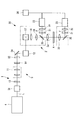
本実施形態に係る光学装置1は、フェムト秒パルスレーザ光源(以下、単にレーザ光源という。)4と、該レーザ光源4から出射されたパルスレーザ光Lを伝送する伝送光学系5とを備えている。
伝送光学系5は、顕微教本体3を含む光学系全体の群速度分散を補償するためのネガティブチャープ光学系6と、該ネガティブチャープ光学系6から出射されたパルスレーザ光Lの光軸ズレを調節するアライメント調節光学系7と、ビーム整形光学系8と、音響光学素子9と、該音響光学素子9から出射されたパルスレーザ光Lの光軸ズレを調節するアライメント調節光学系10と、視準光学系11と、アライメント調節光学系12と、ビーム整形光学系8を挟んで配置された2枚のλ/4波長板13,14と、視準光学系11の前段に配置されたλ/4波長板15とを備えている。
The optical device 1 according to this embodiment includes a femtosecond pulse laser light source (hereinafter simply referred to as a laser light source) 4 and a transmission optical system 5 that transmits the pulse laser light L emitted from the
The transmission optical system 5 includes a negative chirp
ネガティブチャープ光学系6は、例えば、一対のプリズム6a,6bとミラー6cとから構成されている。あるいはグレーティング対により構成されていてもよい。プリズム6a,6bどうしの間隔あるいはグレーティングどうしの間隔を調節することで、レーザ光源4から顕微鏡本体3の対物レンズ3aに至る全光学系における群速度分散を補償するようになっている。
The negative chirp
前記アライメント調節光学系7,10,12は、例えば、レーザ光軸の位置および角度を調節可能な2枚のミラー(図示略)を備え、パルスレーザ光Lの光軸の位置と偏向を調節し、音響光学素子、視準光学系11あるいは顕微鏡本体3に対して、それぞれ適正な位置と角度で精度よく入射させるように構成されている。図中、符号16は、レーザ光源4から発せられたパルスレーザ光Lを反射してネガティブチャープ光学系6に指向させる一方、ネガティブチャープ光学系6から出力されたパルスレーザ光Lの光軸から紙面に垂直方向に外れた位置に配置されているミラーである。
The alignment adjusting
ビーム整形光学系8は、ネガティブチャープ光学系6を通過し、アライメント調節光学系7によって光軸ズレを補正されたパルスレーザ光Lの光束径を絞り、音響光学素子9の結晶(図示略)の有効範囲内に漏れなく入射させるように構成されている。
本実施形態においては、ビーム整形光学系8は、例えば、凸平レンズと平凹レンズとを組み合わせたガリレイ型のビームエキスパンダにより構成されている。
The beam shaping optical system 8 passes through the negative chirp
In the present embodiment, the beam shaping optical system 8 is configured by, for example, a Galilean beam expander that combines a convex flat lens and a plano-concave lens.
前記音響光学素子9は、例えば、AOMであって、2酸化テルルからなる結晶に接着された圧電素子からなるトランスデューサによって結晶に加える音響波の振幅を変更することにより、結晶内におけるパルスレーザ光Lの回折強度を変化させ、出射されるパルスレーザ光Lの強度を、音響波の振幅に応じた所定の割合で変調するようになっている。
The
視準光学系11は、例えば、凸平レンズと平凸レンズとからなるビームエキスパンダにより構成されている。視準光学系11は、ビーム整形光学系8により音響光学素子9の有効範囲を漏れなく通過するようにその光束径およびビームダイバージェンスを補正され、かつ、アライメント調節光学系12により光軸の位置および偏向を調節されたパルスレーザ光Lが、顕微鏡本体3の対物レンズ3aに対して適正な光束径とビームダイバージェンスになるように、その光束径およびダイバージェンスを補正するようになっている。さらに具体的には、視準光学系11は、対物レンズ3aの瞳位置において、パルスレーザ光Lが、その瞳径と略同等の光束径を有するように、その光束径およびダイバージェンスを補正するようになっている。
The collimating
本実施形態においては、ビーム整形光学系(反射光発生源)8および視準光学系11において、それぞれに入射されるパルスレーザ光Lの一部が反射されるようになっている。
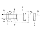
ビーム整形光学系8および視準光学系11の前段に設けられたλ/4波長板13,15は、図2に示されるように、これらビーム整形光学系8または視準光学系11に入射される入射パルスレーザ光Lを直線偏光P1から円偏光P2に変換するとともに、これらビーム整形光学系8または視準光学系11において反射された反射パルスレーザ光L′を円偏光P2′から直線偏光P3に変換するようになっている。この際、反射により円偏光P2′の回転方向が円偏光P2に対して反転されるので、反射パルスレーザ光L′がλ/4波長板13により円偏光P2′から直線偏光P3に変換される際には、入射パルスレーザ光Lに対して偏光方向が90°回転している。
In the present embodiment, the beam shaping optical system (reflected light generation source) 8 and the collimating
As shown in FIG. 2, the λ / 4
また、ビーム整形光学系8の後段に設けられたλ/4波長板14は、前段に設けられたλ/4波長板13により変換された円偏光P2のパルスレーザ光Lをそのまま通過させるので、入射パルスレーザ光Lと同一の偏光方向を有する直線偏光P1として後段の音響光学素子9に入射させることができるようになっている。
Further, the λ / 4
顕微鏡本体3は、伝送光学系5から伝送されてきたパルスレーザ光Lを2次元的に走査するスキャナ17、走査されたパルスレーザ光Lを伝送し集光する瞳投影レンズ18、結像レンズ19および対物レンズ3a、対物レンズ3aにより集光された標本Aからの蛍光Fをパルスレーザ光Lから分岐するダイクロイックミラー20、バリアフィルタ21および集光レンズ22を介した蛍光Fを検出する光検出器23、および該光検出器23からの信号に基づいて蛍光画像を構築する画像処理装置24を備えている。
The
このように構成された本実施形態に係る光学装置1の作用について説明する。
本実施形態に係る光学装置1によれば、アライメント調整光学系7により光軸ズレが補正され、ビーム整形光学系8によりビーム径が調整されたパルスレーザ光Lが音響光学素子9の結晶に漏れなく入射される。音響光学素子9に入射されるパルスレーザ光Lは、図2に示されるように、2枚のλ/4波長板13,14を通過させられることにより、その偏光方向が、レーザ光源4から出射されたままの直線偏光状態に維持される。したがって、出射時と同一の適正な直線偏光状態のまま音響光学素子9に入射させることができ、音響光学素子9におけるパルスレーザ光Lの変調を適正に行うことができる。
The operation of the optical apparatus 1 according to this embodiment configured as described above will be described.
According to the optical device 1 according to the present embodiment, the pulsed laser light L whose optical axis deviation is corrected by the alignment adjusting
また、ビーム整形光学系8および視準光学系11においては、パルスレーザ光Lの一部が反射されることとなるが、いずれも同一のλ/4波長板13,15を通過させられることにより、入射パルスレーザ光Lとは90°偏光方向の異なる直線偏光のパルスレーザ光L′としてレーザ光源4側に戻される。このような90°偏光方向の異なる直線偏光のパルスレーザ光L′は、レーザ光源4に備えられているブリュースターウィンドウ(図示略)等によって容易に遮断することができ、レーザ光源4の内部に戻ることを確実に防止して、レーザ発振の不安定化の発生を未然に防止することができる。
Further, in the beam shaping optical system 8 and the collimation
特に、レーザ光源4として、ピコ秒以下の極短パルスレーザ光を発振するパルスレーザ光源あるいはレーザダイオードを採用することにより、反射戻り光によるレーザ発振の不安定化を生じ易いこれらのレーザ光源4を用いた場合においても、確実に反射戻り光を遮断することができるという利点がある。
In particular, by adopting a pulse laser light source or a laser diode that oscillates an ultrashort pulse laser beam of picosecond or less as the
このようなλ/4波長板13,15は、光アイソレータと比較して、構成が簡易であって安価に入手でき、確実に反射戻り光を遮断可能にすることができ、磁気を利用しないので外部に悪影響を与えず、かつ、群速度遅延分散が小さいという利点がある。
なお、λ/4波長板15を通過したパルスレーザ光Lは、円偏光となって顕微鏡本体3に入射されるが、2光子励起効果自体は、偏光に依存しないので、問題はない。
Such λ / 4
The pulsed laser light L that has passed through the λ / 4
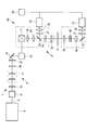
また、本実施形態においては音響光学素子9を偏光依存素子として例示し、該音響光学素子9への直線偏光状態を確保することとしたが、これに代えて、図3に示されるように、SHG顕微鏡30に適用することとしてもよい。
図中、符号31は出力変調器、符号32は直線偏光を維持したまま、その方向を回転させるλ/2波長板、符号33はコンデンサレンズ、符号34,35はミラーである。
In the present embodiment, the
In the figure,
このSHG顕微鏡30においては、視準光学系11のみが反射光発生源となるので、視準光学系11を挟む2箇所にλ/4波長板13,14を配置することにより、上記実施形態と同様にして、顕微鏡本体3′に入射させるパルスレーザ光Lの直線偏光状態を維持し、かつ、レーザ光源4への反射戻り光を確実に遮断し易くすることができる。
In this
また、図4に示されるように、微分干渉顕微鏡40に適用することにしてもよい。
図中、符号41は照明側微分干渉素子、符号42は観察側微分干渉素子、符号43は偏光素子である。
このようにすることで、偏光依存素子としての微分干渉顕微鏡40の顕微鏡本体3″への入射パルスレーザ光Lの直線偏光状態を確保することができる。また、視準光学系11における反射パルスレーザ光が、レーザ光源4に戻ることを確実に防止することができる。
Further, as shown in FIG. 4, the
In the figure,
By doing so, it is possible to ensure the linear polarization state of the pulse laser beam L incident on the microscope
L パルスレーザ光
1 光学装置
3′,3″ 顕微鏡本体(偏光依存素子)
4 レーザ光源
5 伝送光学系
8 ビーム整形光学系(反射光発生源)
9 音響光学素子(偏光依存素子)
11 視準光学系(反射光発生源)
13,14,15 λ/4波長板
L Pulse laser beam 1
4 Laser light source 5 Transmission optical system 8 Beam shaping optical system (reflected light generation source)
9 Acousto-optic elements (polarization dependent elements)
11 Collimation optics (reflected light source)
13, 14, 15 λ / 4 wave plate
Claims (4)
該レーザ光源から発せられた極短パルスレーザ光を伝送する伝送光学系と、
該伝送光学系により伝送された極短パルスレーザ光を入射させ、その入射偏光状態に応じて出射光特性が変化する偏光依存素子とを備え、
前記伝送光学系が、伝送される極短パルスレーザ光の一部を反射する反射光発生源を備え、
該反射光発生源を挟む位置であり、かつ前記偏光依存素子より前段に、一対のλ/4波長板が配置されているレーザ顕微鏡。 A laser light source that oscillates an ultrashort pulse laser beam of picoseconds or less ;
A transmission optical system for transmitting an ultrashort pulse laser beam emitted from the laser light source;
A polarization-dependent element in which an ultrashort pulse laser beam transmitted by the transmission optical system is incident, and an output light characteristic is changed according to the incident polarization state;
The transmission optical system includes a reflected light generation source that reflects a part of the transmitted ultrashort pulse laser beam,
A laser microscope in which a pair of λ / 4 wavelength plates are arranged at a position sandwiching the reflected light generation source and in front of the polarization dependent element .
前記偏光依存素子として音響光学素子を備える請求項1に記載のレーザ顕微鏡。The laser microscope according to claim 1, comprising an acousto-optic element as the polarization dependent element.
前記偏光依存素子として、前記極短パルスレーザ光の偏光方向を回転させる直線偏光回転ユニットを備える請求項1に記載のレーザ顕微鏡。The laser microscope according to claim 1, further comprising a linear polarization rotation unit that rotates a polarization direction of the ultrashort pulse laser light as the polarization dependent element.
前記偏光依存素子が照明側微分干渉素子である請求項1に記載のレーザ顕微鏡。The laser microscope according to claim 1, wherein the polarization-dependent element is an illumination-side differential interference element.
Priority Applications (3)
| Application Number | Priority Date | Filing Date | Title |
|---|---|---|---|
| JP2007292413A JP5259157B2 (en) | 2007-11-09 | 2007-11-09 | Laser microscope |
| US12/255,021 US8279521B2 (en) | 2007-11-09 | 2008-10-21 | Optical device and laser microscope |
| EP08018490.6A EP2060946B1 (en) | 2007-11-09 | 2008-10-22 | Optical device and laser microscope |
Applications Claiming Priority (1)
| Application Number | Priority Date | Filing Date | Title |
|---|---|---|---|
| JP2007292413A JP5259157B2 (en) | 2007-11-09 | 2007-11-09 | Laser microscope |
Publications (2)
| Publication Number | Publication Date |
|---|---|
| JP2009116280A JP2009116280A (en) | 2009-05-28 |
| JP5259157B2 true JP5259157B2 (en) | 2013-08-07 |
Family
ID=40347821
Family Applications (1)
| Application Number | Title | Priority Date | Filing Date |
|---|---|---|---|
| JP2007292413A Expired - Fee Related JP5259157B2 (en) | 2007-11-09 | 2007-11-09 | Laser microscope |
Country Status (3)
| Country | Link |
|---|---|
| US (1) | US8279521B2 (en) |
| EP (1) | EP2060946B1 (en) |
| JP (1) | JP5259157B2 (en) |
Families Citing this family (5)
| Publication number | Priority date | Publication date | Assignee | Title |
|---|---|---|---|---|
| JP5101393B2 (en) * | 2008-05-26 | 2012-12-19 | オリンパス株式会社 | Laser microscope |
| TWI594828B (en) * | 2009-05-28 | 2017-08-11 | 伊雷克托科學工業股份有限公司 | Acousto-optic deflector applications in laser processing of features in a workpiece, and related laser processing method |
| JP6253395B2 (en) * | 2013-12-19 | 2017-12-27 | オリンパス株式会社 | Image generation system |
| US9851570B2 (en) | 2014-09-18 | 2017-12-26 | Ipg Photonics Corporation | Beam shaping of high intensity high frequency optical output |
| WO2019164894A1 (en) * | 2018-02-20 | 2019-08-29 | Arizona Board Of Regents On Behalf Of The University Of Arizona | Polarization preserving bidirectional optical element |
Family Cites Families (15)
| Publication number | Priority date | Publication date | Assignee | Title |
|---|---|---|---|---|
| US3700307A (en) * | 1971-04-05 | 1972-10-24 | United Aircraft Corp | Adjustable nonlinearly transmissive optical device |
| US4643575A (en) * | 1984-09-04 | 1987-02-17 | Raytheon Company | Fizeau interferometer |
| US5031182A (en) * | 1989-05-18 | 1991-07-09 | Amoco Corporation | Single-frequency laser of improved amplitude stability |
| EP0483827B1 (en) * | 1990-10-31 | 1997-01-02 | Dainippon Screen Mfg. Co., Ltd. | Apparatus for scanning drum inner face and method of scanning therefor |
| JPH05203878A (en) * | 1992-01-27 | 1993-08-13 | Jeol Ltd | Scanning laser microscope |
| JP2682339B2 (en) * | 1992-07-20 | 1997-11-26 | 株式会社日立製作所 | Solid state laser resonator |
| US5359622A (en) * | 1993-03-30 | 1994-10-25 | Trw Inc. | Radial polarization laser resonator |
| JPH0835180A (en) * | 1994-07-19 | 1996-02-06 | Kotec Kk | Resin processing method for textiles using sliver yarn |
| JPH0835810A (en) * | 1994-07-21 | 1996-02-06 | Nikon Corp | Optical device |
| JP2000330052A (en) * | 1999-05-20 | 2000-11-30 | Fuji Photo Film Co Ltd | Internal surface scanning type image recorder |
| US7151632B2 (en) * | 2001-01-12 | 2006-12-19 | University Of Rochester | Apparatus for production of an inhomogeneously polarized optical beam for use in illumination and a method thereof |
| JP4325135B2 (en) * | 2001-09-25 | 2009-09-02 | セイコーエプソン株式会社 | Lighting device and projector |
| JP4242627B2 (en) | 2002-10-31 | 2009-03-25 | オリンパス株式会社 | Laser microscope |
| JP2006275917A (en) * | 2005-03-30 | 2006-10-12 | Olympus Corp | Multiphoton excitation type observation device and light source device for multiphoton excitation type observation |
| JP2007292413A (en) | 2006-04-27 | 2007-11-08 | Sharp Corp | Heat generating device with air blowing function |
-
2007
- 2007-11-09 JP JP2007292413A patent/JP5259157B2/en not_active Expired - Fee Related
-
2008
- 2008-10-21 US US12/255,021 patent/US8279521B2/en not_active Expired - Fee Related
- 2008-10-22 EP EP08018490.6A patent/EP2060946B1/en not_active Not-in-force
Also Published As
| Publication number | Publication date |
|---|---|
| EP2060946A2 (en) | 2009-05-20 |
| EP2060946B1 (en) | 2017-05-10 |
| JP2009116280A (en) | 2009-05-28 |
| US20090122397A1 (en) | 2009-05-14 |
| US8279521B2 (en) | 2012-10-02 |
| EP2060946A3 (en) | 2011-11-30 |
Similar Documents
| Publication | Publication Date | Title |
|---|---|---|
| JP4729269B2 (en) | Laser scanning microscope | |
| JP5463913B2 (en) | Broadband optical amplifier, optical pulse generator, and optical instrument | |
| US10095017B2 (en) | Microscope and microscopy method | |
| JP5307439B2 (en) | Laser microscope | |
| JP5259157B2 (en) | Laser microscope | |
| JP5216544B2 (en) | Terahertz wave generator | |
| CN105683818B (en) | Scanning microscope with polarized sample illumination | |
| CN112882215A (en) | Fluorescent microscope and component group and module for upgrading a fluorescent microscope | |
| EP3098642B1 (en) | Microscope comprising scanning optical system | |
| CN110632045A (en) | A method and device for generating parallel super-resolution focal spots | |
| KR102386039B1 (en) | EUV radiation generating device comprising a polarizer arrangement and a polarizer arrangement | |
| JP5101393B2 (en) | Laser microscope | |
| TWI738675B (en) | Polariser arrangement, euv radiation generating apparatus and method for the linear polarisation of a laser beam | |
| JP2006242570A (en) | Surface shape measuring apparatus | |
| CN106575030A (en) | Microscope with beam splitter assembly | |
| JP5701573B2 (en) | Scanner, scanning illumination device, and scanning observation device | |
| JP2006275915A (en) | Multiphoton excitation type observation device, and light source device for multiphoton excitation type observation | |
| CN110186896B (en) | A fully electronically controlled dual Stokes optical wavelength tuning device and method | |
| JP2006275917A (en) | Multiphoton excitation type observation device and light source device for multiphoton excitation type observation | |
| JP4666619B2 (en) | Terahertz wave imaging device | |
| JP2011128287A (en) | Multiphoton microscope | |
| JP4642525B2 (en) | Multiphoton excitation observation device | |
| WO2024241902A1 (en) | Nonlinear optical microscope | |
| JP2011064890A (en) | Light source device | |
| JP2011053489A (en) | Laser device |
Legal Events
| Date | Code | Title | Description |
|---|---|---|---|
| A621 | Written request for application examination |
Free format text: JAPANESE INTERMEDIATE CODE: A621 Effective date: 20100830 |
|
| A521 | Written amendment |
Free format text: JAPANESE INTERMEDIATE CODE: A523 Effective date: 20111005 |
|
| A977 | Report on retrieval |
Free format text: JAPANESE INTERMEDIATE CODE: A971007 Effective date: 20120316 |
|
| A131 | Notification of reasons for refusal |
Free format text: JAPANESE INTERMEDIATE CODE: A131 Effective date: 20120911 |
|
| A521 | Written amendment |
Free format text: JAPANESE INTERMEDIATE CODE: A523 Effective date: 20121112 |
|
| TRDD | Decision of grant or rejection written | ||
| A01 | Written decision to grant a patent or to grant a registration (utility model) |
Free format text: JAPANESE INTERMEDIATE CODE: A01 Effective date: 20130409 |
|
| A61 | First payment of annual fees (during grant procedure) |
Free format text: JAPANESE INTERMEDIATE CODE: A61 Effective date: 20130424 |
|
| FPAY | Renewal fee payment (event date is renewal date of database) |
Free format text: PAYMENT UNTIL: 20160502 Year of fee payment: 3 |
|
| R151 | Written notification of patent or utility model registration |
Ref document number: 5259157 Country of ref document: JP Free format text: JAPANESE INTERMEDIATE CODE: R151 |
|
| S531 | Written request for registration of change of domicile |
Free format text: JAPANESE INTERMEDIATE CODE: R313531 |
|
| R350 | Written notification of registration of transfer |
Free format text: JAPANESE INTERMEDIATE CODE: R350 |
|
| R250 | Receipt of annual fees |
Free format text: JAPANESE INTERMEDIATE CODE: R250 |
|
| LAPS | Cancellation because of no payment of annual fees |