JP5259124B2 - High temperature regenerator and absorption refrigerator - Google Patents

High temperature regenerator and absorption refrigerator Download PDF

Info

Publication number
JP5259124B2
JP5259124B2 JP2007147397A JP2007147397A JP5259124B2 JP 5259124 B2 JP5259124 B2 JP 5259124B2 JP 2007147397 A JP2007147397 A JP 2007147397A JP 2007147397 A JP2007147397 A JP 2007147397A JP 5259124 B2 JP5259124 B2 JP 5259124B2
Authority
JP
Japan
Prior art keywords
gas
liquid
solution
liquid separator
refrigerant vapor
Prior art date
Legal status (The legal status is an assumption and is not a legal conclusion. Google has not performed a legal analysis and makes no representation as to the accuracy of the status listed.)
Expired - Fee Related
Application number
JP2007147397A
Other languages
Japanese (ja)
Other versions
JP2008008608A (en
Inventor
與四郎 竹村
智芳 入江
純 村田
Current Assignee (The listed assignees may be inaccurate. Google has not performed a legal analysis and makes no representation or warranty as to the accuracy of the list.)
Ebara Refrigeration Equipment and Systems Co Ltd
Original Assignee
Ebara Refrigeration Equipment and Systems Co Ltd
Priority date (The priority date is an assumption and is not a legal conclusion. Google has not performed a legal analysis and makes no representation as to the accuracy of the date listed.)
Filing date
Publication date
Application filed by Ebara Refrigeration Equipment and Systems Co Ltd filed Critical Ebara Refrigeration Equipment and Systems Co Ltd
Priority to JP2007147397A priority Critical patent/JP5259124B2/en
Publication of JP2008008608A publication Critical patent/JP2008008608A/en
Application granted granted Critical
Publication of JP5259124B2 publication Critical patent/JP5259124B2/en
Expired - Fee Related legal-status Critical Current
Anticipated expiration legal-status Critical

Links

Images

Classifications

    • YGENERAL TAGGING OF NEW TECHNOLOGICAL DEVELOPMENTS; GENERAL TAGGING OF CROSS-SECTIONAL TECHNOLOGIES SPANNING OVER SEVERAL SECTIONS OF THE IPC; TECHNICAL SUBJECTS COVERED BY FORMER USPC CROSS-REFERENCE ART COLLECTIONS [XRACs] AND DIGESTS
    • Y02TECHNOLOGIES OR APPLICATIONS FOR MITIGATION OR ADAPTATION AGAINST CLIMATE CHANGE
    • Y02ATECHNOLOGIES FOR ADAPTATION TO CLIMATE CHANGE
    • Y02A30/00Adapting or protecting infrastructure or their operation
    • Y02A30/27Relating to heating, ventilation or air conditioning [HVAC] technologies
    • YGENERAL TAGGING OF NEW TECHNOLOGICAL DEVELOPMENTS; GENERAL TAGGING OF CROSS-SECTIONAL TECHNOLOGIES SPANNING OVER SEVERAL SECTIONS OF THE IPC; TECHNICAL SUBJECTS COVERED BY FORMER USPC CROSS-REFERENCE ART COLLECTIONS [XRACs] AND DIGESTS
    • Y02TECHNOLOGIES OR APPLICATIONS FOR MITIGATION OR ADAPTATION AGAINST CLIMATE CHANGE
    • Y02BCLIMATE CHANGE MITIGATION TECHNOLOGIES RELATED TO BUILDINGS, e.g. HOUSING, HOUSE APPLIANCES OR RELATED END-USER APPLICATIONS
    • Y02B30/00Energy efficient heating, ventilation or air conditioning [HVAC]
    • Y02B30/62Absorption based systems

Landscapes

  • Sorption Type Refrigeration Machines (AREA)

Description

本発明は高温再生器及び吸収冷凍機に関し、特に負荷の変化にかかわらず冷媒蒸気と高濃度の吸収溶液とを確実に取り出すことができる高温再生器、及びこのような高温再生器を備える吸収冷凍機に関する。   The present invention relates to a high-temperature regenerator and an absorption refrigerator, and particularly to a high-temperature regenerator capable of reliably taking out refrigerant vapor and a high-concentration absorbing solution regardless of changes in load, and an absorption refrigeration equipped with such a high-temperature regenerator. Related to the machine.

近年の地球環境保全意識の高まりを背景に、より省エネルギーに資する三重効用冷凍機の採用が推奨されている。三重効用吸収冷凍機では、一般に、作動温度が最も高い高温再生器内の圧力が大気圧以上となるので、貫流ボイラ式の高温再生器が適している。   With the recent increase in awareness of global environmental conservation, the adoption of triple effect refrigerators that contribute to energy conservation is recommended. In the triple effect absorption refrigerator, since the pressure in the high-temperature regenerator having the highest operating temperature is generally equal to or higher than the atmospheric pressure, a once-through boiler type high-temperature regenerator is suitable.

図7に、吸収冷凍機に用いられる従来の貫流ボイラ式の高温再生器90を示す。高温再生器90は、環状の上部管寄せ91及び下部管寄せ92の間に多数の液管93を設け、その内側上部の中央部に燃焼装置94を設けている。この高温再生器90は次のように作用する。吸収器等(不図示)から下部管寄せ92に供給された希吸収溶液Swを、燃焼装置94によって、加熱沸騰させ、発生した冷媒蒸気Vと濃度が上昇した吸収溶液S(以下濃溶液Sという)の混合体を連絡管96を介して気液分離器97に導く。気液分離器97内で濃溶液Sと分離された冷媒蒸気Vは、気液分離器97の上部に形成された取り出し口97aから高温再生器90よりも作動温度が低い再生器(不図示)に熱源として供給され、濃溶液Sは気液分離器97の下部に形成された濃溶液取り出し口97bから吸収器等(不図示)に向けて導出される。濃溶液取り出し口97bから導出されない余剰の濃溶液Sは濃溶液戻り管98を介して下部管寄せ92に還流する。そして、作動温度が低い再生器(不図示)への冷媒蒸気Vの供給、及び吸収器等(不図示)への濃溶液Sの供給を安定して行うために、気液分離器97では冷媒蒸気相及び濃溶液相の両相が分離された状態で存在するように調整される。   FIG. 7 shows a conventional once-through boiler type high-temperature regenerator 90 used in an absorption refrigerator. The high temperature regenerator 90 is provided with a large number of liquid pipes 93 between an annular upper header 91 and a lower header 92, and a combustion device 94 is provided at the center of the inner upper part thereof. The high temperature regenerator 90 operates as follows. The diluted absorbent solution Sw supplied from the absorber or the like (not shown) to the lower header 92 is heated and boiled by the combustion device 94, and the generated refrigerant vapor V and the absorbed solution S (hereinafter referred to as the concentrated solution S) whose concentration is increased. ) Is led to the gas-liquid separator 97 through the communication tube 96. The refrigerant vapor V separated from the concentrated solution S in the gas-liquid separator 97 has a regenerator (not shown) whose operating temperature is lower than that of the high-temperature regenerator 90 from an outlet 97a formed in the upper part of the gas-liquid separator 97. The concentrated solution S is led out toward an absorber (not shown) from a concentrated solution outlet 97b formed in the lower part of the gas-liquid separator 97. Excess concentrated solution S that is not led out from the concentrated solution outlet 97 b returns to the lower header 92 through the concentrated solution return pipe 98. In order to stably supply the refrigerant vapor V to a regenerator (not shown) having a low operating temperature and supply the concentrated solution S to an absorber or the like (not shown), the gas-liquid separator 97 uses a refrigerant. The vapor phase and the concentrated solution phase are adjusted so as to exist in a separated state.

しかしながら、吸収冷凍機の高温再生器では冷凍負荷の変化に伴い、高温再生器に供給される希溶液量が変化し、同時に、発生する冷媒蒸気量も変化する。上述の貫流ボイラ式の高温再生器(図7参照)では、負荷が高い場合には高温再生器に供給される希溶液量が増大し燃焼装置の燃焼量が大きくなるために気液分離器内に供給される濃溶液と冷媒蒸気量が多量となり、気液の分離が不十分となって冷媒蒸気中に濃溶液が混入する場合があり、また、運転状況によっては濃溶液の取り出し量が安定しない場合があった。   However, in the high-temperature regenerator of the absorption refrigerator, the amount of dilute solution supplied to the high-temperature regenerator changes with the change of the refrigeration load, and at the same time, the amount of generated refrigerant vapor also changes. In the once-through boiler high-temperature regenerator described above (see FIG. 7), when the load is high, the amount of dilute solution supplied to the high-temperature regenerator increases and the combustion amount of the combustion device increases. The amount of concentrated solution and refrigerant vapor supplied to the tank becomes large, resulting in insufficient separation of gas and liquid, and the concentrated solution may be mixed in the refrigerant vapor. There was a case not to.

本発明は上述の課題に鑑み、高温再生器における負荷の変化にかかわらず気液分離器から冷媒蒸気と高濃度の吸収溶液とを確実に取り出すことができる高温再生器、及びこのような高温再生器を備える吸収冷凍機を提供することを目的とする。   In view of the above-described problems, the present invention provides a high-temperature regenerator capable of reliably taking out refrigerant vapor and a high-concentration absorbing solution from a gas-liquid separator regardless of a change in load in the high-temperature regenerator, and such a high-temperature regeneration. An object of the present invention is to provide an absorption refrigerator equipped with a refrigerator.

上記目的を達成するために、本発明の第1の態様に係る高温再生器は、例えば図1に示すように、加熱され濃縮される希溶液Swを下方から上方に向かって流す液管10と;液管10に、液管10の下部から希溶液Swを供給する液室14と;液管10で希溶液Swが加熱されることによって発生した1次冷媒蒸気Vpと濃度が上昇した濃溶液Saとの混合流体Fmを導入し、混合流体Fmから1次冷媒蒸気Vpと濃溶液Saとを分離する、液室14と連通する第1の気液分離器22と;1次冷媒蒸気Vpを導入し、1次冷媒蒸気Vpに同伴する、希溶液Swよりも高濃度の溶液である戻り溶液Srと、導出冷媒蒸気Vaとに分離する第2の気液分離器24とを備える。ここで「導出冷媒蒸気」は冷媒蒸気であり、1次冷媒蒸気との区別を容易にするためにこのように呼称する。   In order to achieve the above object, a high temperature regenerator according to a first aspect of the present invention includes a liquid pipe 10 for flowing a dilute solution Sw to be heated and concentrated from below to above as shown in FIG. A liquid chamber 14 for supplying the liquid pipe 10 with the dilute solution Sw from the lower part of the liquid pipe 10; a concentrated solution having a concentration increased with the primary refrigerant vapor Vp generated by heating the dilute solution Sw in the liquid pipe 10; A first fluid-liquid separator 22 that communicates with the liquid chamber 14 and that introduces a mixed fluid Fm with Sa and separates the primary refrigerant vapor Vp and the concentrated solution Sa from the mixed fluid Fm; A return solution Sr, which is introduced and accompanied by the primary refrigerant vapor Vp, is a solution having a higher concentration than the dilute solution Sw, and a second gas-liquid separator 24 that separates into the derived refrigerant vapor Va. Here, the “derived refrigerant vapor” is a refrigerant vapor and is referred to as such in order to facilitate the distinction from the primary refrigerant vapor.

このように構成すると、第1の気液分離器から濃溶液を取り出し、第2の気液分離器から導出冷媒蒸気を取り出すことができ、濃溶液と導出冷媒蒸気とを確実に取り出すことができる高温再生器となる。   With this configuration, the concentrated solution can be taken out from the first gas-liquid separator and the derived refrigerant vapor can be taken out from the second gas-liquid separator, so that the concentrated solution and the derived refrigerant vapor can be reliably taken out. It becomes a high temperature regenerator.

また、例えば図1に示すように、上記本発明の第1の態様に係る高温再生器32Aにおいて、液管10で発生した混合流体Fmが第1の気液分離器22に導入される際の流通抵抗(圧力損失)が、第1の気液分離器22への濃溶液Saの導入の妨げにならない程度に低減されて構成されるとよい。このように構成すると、負荷が低く液管で発生する冷媒蒸気量が少ないために、冷媒蒸気に同伴して気液分離器に導かれるはずの液管で発生した濃溶液が気液分離器まで到達しないことを回避することができ、気液分離器内に濃溶液が貯留せずに高温再生器から濃溶液が取り出せないことを回避することができる。   For example, as shown in FIG. 1, in the high temperature regenerator 32A according to the first aspect of the present invention, the mixed fluid Fm generated in the liquid pipe 10 is introduced into the first gas-liquid separator 22. It is preferable that the flow resistance (pressure loss) be reduced to such an extent that the introduction of the concentrated solution Sa into the first gas-liquid separator 22 is not hindered. With this configuration, since the load is low and the amount of refrigerant vapor generated in the liquid pipe is small, the concentrated solution generated in the liquid pipe that should be led to the gas-liquid separator along with the refrigerant vapor is transferred to the gas-liquid separator. Therefore, it is possible to prevent the concentrated solution from being taken out from the high temperature regenerator without the concentrated solution being stored in the gas-liquid separator.

また、例えば図1に示すように、上記本発明の第1の態様に係る高温再生器32Aにおいて、第2の気液分離器24に形成された導出冷媒蒸気Vaを導出する導出冷媒蒸気導出口24eが、第1の気液分離器22に形成された1次冷媒蒸気Vpを導出する1次冷媒蒸気導出口22eよりも高所に位置するように構成されていてもよい。このように構成すると、導出冷媒蒸気導出口から取り出される導出冷媒蒸気が、十分に気液分離されたものとなる。   For example, as shown in FIG. 1, in the high-temperature regenerator 32A according to the first aspect of the present invention, a derived refrigerant vapor outlet for deriving the derived refrigerant vapor Va formed in the second gas-liquid separator 24. 24e may be configured to be positioned higher than the primary refrigerant vapor outlet port 22e through which the primary refrigerant vapor Vp formed in the first gas-liquid separator 22 is derived. With this configuration, the derived refrigerant vapor taken out from the derived refrigerant vapor outlet is sufficiently gas-liquid separated.

また、本発明の第2の態様に係る高温再生器は、例えば図1に示すように、上記本発明の第1の態様に係る高温再生器32Aにおいて、第1の気液分離器22内の濃溶液Saを液室14に導く第1の戻り管25と;戻り溶液Srを液室14に導く第2の戻り管26とを備える。   Further, the high temperature regenerator according to the second aspect of the present invention is, for example, as shown in FIG. 1, in the high temperature regenerator 32A according to the first aspect of the present invention, A first return pipe 25 for guiding the concentrated solution Sa to the liquid chamber 14; and a second return pipe 26 for guiding the return solution Sr to the liquid chamber 14.

このように構成すると、第1の気液分離器内の余剰分の濃溶液と第2の気液分離器内の戻り溶液を液室に導くことが可能になり、第1の気液分離器の濃溶液導出口から導出される濃溶液の流量を安定させることができる。   If comprised in this way, it will become possible to guide the excess concentrated solution in the first gas-liquid separator and the return solution in the second gas-liquid separator to the liquid chamber, and the first gas-liquid separator It is possible to stabilize the flow rate of the concentrated solution derived from the concentrated solution outlet.

また、本発明の第3の態様に係る高温再生器は、例えば図4に示すように、上記本発明の第2の態様に係る高温再生器32Eにおいて、第2の気液分離器24の最下部に戻り溶液Srを液室14に向けて導出する戻り溶液導出口24rが形成され、戻り溶液導出口24rよりも高所の第2の気液分離器に導出冷媒蒸気Vaを導出する導出冷媒蒸気導出口24eが形成され;戻り溶液導出口24rが形成された最下部が、第1の気液分離器22内の濃溶液Saの常用液位SaLよりも高所に位置するように構成されている。ここで、戻り溶液導出口及び導出冷媒蒸気導出口が水平面以外に形成されている場合は、戻り溶液導出口の上端よりも導出冷媒蒸気導出口の下端が高所に位置するように、戻り溶液導出口及び導出冷媒蒸気導出口が形成される。また「常用液位」とは、典型的には、主として運転される運転負荷時(例えば、運転時間が最も長くなる運転負荷時等)における第1の気液分離器内の濃溶液の液位であって、第1の気液分離器内の濃溶液の最高液位と最低液位との間の液位である。   In addition, the high temperature regenerator according to the third aspect of the present invention is the same as that of the second gas-liquid separator 24 in the high temperature regenerator 32E according to the second aspect of the present invention, for example, as shown in FIG. A return solution outlet 24r for returning the solution Sr toward the liquid chamber 14 is formed in the lower part, and the outlet refrigerant for leading the outlet refrigerant vapor Va to the second gas-liquid separator higher than the return solution outlet 24r. A vapor outlet 24e is formed; the lowermost portion where the return solution outlet 24r is formed is configured to be positioned higher than the normal liquid level SaL of the concentrated solution Sa in the first gas-liquid separator 22. ing. Here, when the return solution outlet and the outlet refrigerant vapor outlet are formed on a plane other than the horizontal plane, the lower end of the outlet refrigerant vapor outlet is positioned higher than the upper end of the return solution outlet. An outlet and an outlet refrigerant vapor outlet are formed. In addition, the “normal liquid level” typically means the liquid level of the concentrated solution in the first gas-liquid separator when the operation load is mainly operated (for example, the operation load when the operation time is longest). And a liquid level between the highest liquid level and the lowest liquid level of the concentrated solution in the first gas-liquid separator.

このように構成すると、導出冷媒蒸気導出口から導出される導出冷媒蒸気が、この高温再生器が吸収冷凍機に組み込まれたときの該吸収冷凍機の作動に支障がない程度に確実に気液分離されることとなる。   With this configuration, the derived refrigerant vapor derived from the derived refrigerant vapor outlet is reliably gas-liquid to an extent that does not hinder the operation of the absorption refrigerator when the high-temperature regenerator is incorporated in the absorption refrigerator. Will be separated.

また、本発明の第4の態様に係る高温再生器は、例えば図2に示すように、上記本発明の第2の態様又は第3の態様に係る高温再生器において、戻り溶液26が第1の戻り管25を経由して液室14に導かれるように構成されている。   Further, as shown in FIG. 2, for example, the high temperature regenerator according to the fourth aspect of the present invention is the high temperature regenerator according to the second aspect or the third aspect of the present invention. The return pipe 25 is led to the liquid chamber 14.

このように構成すると、高温再生器内の保有溶液量を少なくすることができる。   If comprised in this way, the amount of solution holding in a high temperature regenerator can be decreased.

また、本発明の第5の態様に係る高温再生器は、例えば図1に示すように、上記本発明の第1の態様乃至第4の態様のいずれか1つの態様に係る高温再生器32Aにおいて、第1の気液分離器22に、濃溶液Saを吸収冷凍機の吸収器31(図3参照)に向けて導出する濃溶液導出口22nが形成され;濃溶液導出口22nが、作動中における液管10に現れる液面の最低高さと、液管10の上端の高さとの間の高さに位置するように構成されている。ここで「濃溶液を吸収冷凍機の吸収器に向けて導出する」とは、濃溶液を高温再生器から直接吸収器に導くことのみならず、他の再生器を介して吸収器に導くことも含む。また、濃溶液導出口が水平面以外に形成されている場合は、濃溶液導出口の下端を位置関係の基準とする。また「液管に現れる液面」とは、典型的には、液管の両端の圧力差を示す指標であり、例えば希溶液が混合流体となる程の熱を受けない連通管(例えば図1中の連通管11)を液管の両端に接続したときにその連通管内に現れる液面とほぼ等しい液面である。また「液管に現れる液面の最低高さ」とは、典型的には、高温再生器の運転中に維持すべき最低安全液位であって、液管を熱損傷から保護することができる最低の液面である。   A high temperature regenerator according to the fifth aspect of the present invention is a high temperature regenerator 32A according to any one of the first to fourth aspects of the present invention as shown in FIG. The first gas-liquid separator 22 is formed with a concentrated solution outlet 22n for leading the concentrated solution Sa toward the absorber 31 of the absorption refrigerator (see FIG. 3); the concentrated solution outlet 22n is in operation. The liquid pipe 10 is configured to be positioned at a height between the minimum height of the liquid surface appearing in the liquid pipe 10 and the height of the upper end of the liquid pipe 10. Here, “leading the concentrated solution toward the absorber of the absorption refrigerator” means not only directing the concentrated solution from the high-temperature regenerator directly to the absorber, but also guiding it through another regenerator to the absorber. Including. In addition, when the concentrated solution outlet is formed on a plane other than the horizontal plane, the lower end of the concentrated solution outlet is used as a positional relationship reference. The “liquid level appearing in the liquid pipe” is typically an index indicating a pressure difference between both ends of the liquid pipe. For example, the communication pipe (for example, FIG. The liquid level is almost equal to the liquid level appearing in the communication pipe when the middle communication pipe 11) is connected to both ends of the liquid pipe. The “minimum height of the liquid surface appearing in the liquid pipe” is typically the lowest safe liquid level that should be maintained during operation of the high temperature regenerator, and can protect the liquid pipe from thermal damage. The lowest liquid level.

このように構成すると、濃溶液導出口が、作動中における液管に現れる液面の最低高さと、液管の上端の高さとの間の高さに位置するので、ほとんどの場合で濃溶液が第1の気液分離器に存在し、吸収冷凍機の作動に影響を与えることがない。また、高温再生器内の液位を液管の最低液位以上に維持することができ、液管の損傷を防止することができる。   With this configuration, the concentrated solution outlet is located at a height between the lowest level of the liquid level appearing in the liquid tube during operation and the height of the upper end of the liquid tube. It exists in the first gas-liquid separator and does not affect the operation of the absorption refrigerator. Further, the liquid level in the high-temperature regenerator can be maintained above the minimum liquid level of the liquid pipe, and damage to the liquid pipe can be prevented.

また、本発明の第6の態様に係る高温再生器は、例えば図1に示すように、上記本発明の第1の態様乃至第5の態様のいずれか1つの態様に係る高温再生器32Aにおいて、液管10を複数備え;さらに、複数の液管10から混合流体Fmを収集する上部環状部材15を備え;液室14が、複数の液管10に希溶液Swを供給するように構成されている。   Further, the high temperature regenerator according to the sixth aspect of the present invention is, for example, as shown in FIG. 1, in the high temperature regenerator 32A according to any one of the first to fifth aspects of the present invention. A plurality of liquid pipes 10; an upper annular member 15 that collects the mixed fluid Fm from the plurality of liquid pipes 10; and a liquid chamber 14 configured to supply the dilute solution Sw to the plurality of liquid pipes 10. ing.

このように構成すると、液管を複数備えるので希溶液から濃溶液へ再生する溶液量を増加させることあるいは液管を流れる溶液の加熱面積を増加させることができ、複数の液管から混合流体を収集する上部環状部材を備えるので複数の液管で生成された混合流体を収集して第1の気液分離器に導くことができる。   With this configuration, since a plurality of liquid tubes are provided, the amount of solution to be regenerated from a dilute solution to a concentrated solution can be increased, or the heating area of the solution flowing through the liquid tubes can be increased. Since the upper annular member for collecting is provided, the mixed fluid generated by the plurality of liquid pipes can be collected and led to the first gas-liquid separator.

また、本発明の第7の態様に係る高温再生器は、例えば図4に示すように、上記本発明の第6の態様に係る高温再生器32Eにおいて、第1の気液分離器22の上端が、上部環状部材15の上端よりも高所に位置するように構成されている。   Further, the high temperature regenerator according to the seventh aspect of the present invention is the upper end of the first gas-liquid separator 22 in the high temperature regenerator 32E according to the sixth aspect of the present invention as shown in FIG. However, it is comprised so that it may be located in a high place rather than the upper end of the upper annular member 15. FIG.

このように構成すると、第1の気液分離器内における1次冷媒蒸気が占める容積を確保することが可能となり、第1の気液分離器における気液分離効果を向上させることができる。上部環状部材と第1の気液分離器とを連通する混合流体管の流通抵抗を低減させた場合(例えば混合流体管を大径にする又は複数本にする、あるいは長さを短くする等)は、運転負荷が低いために液管で発生する混合流体が少ないことに起因する、1次冷媒蒸気に同伴する濃溶液が第1の気液分離器まで到達しないという不都合を回避することができ、第1の気液分離器内に濃溶液が貯留せずに高温再生器から濃溶液を取り出すことができないという不都合を回避することができて、高温再生器からの濃溶液の取り出しを安定して行うことができる。   If comprised in this way, it will become possible to ensure the volume which the primary refrigerant | coolant vapor | steam occupies in a 1st gas-liquid separator, and the gas-liquid separation effect in a 1st gas-liquid separator can be improved. When the flow resistance of the mixed fluid pipe communicating with the upper annular member and the first gas-liquid separator is reduced (for example, the mixed fluid pipe has a large diameter, a plurality of pipes, or a short length). Can avoid the inconvenience that the concentrated solution accompanying the primary refrigerant vapor does not reach the first gas-liquid separator due to the fact that the mixed fluid generated in the liquid pipe is small due to the low operating load. The inconvenience that the concentrated solution cannot be taken out from the high temperature regenerator without storing the concentrated solution in the first gas-liquid separator can be avoided, and the removal of the concentrated solution from the high temperature regenerator can be stabilized. Can be done.

また、本発明の第8の態様に係る吸収冷凍機は、例えば図3に示すように、上記本発明の第1の態様乃至第7の態様のいずれか1つの態様に係る高温再生器32Aと;冷媒蒸気を凝縮する凝縮器33と;凝縮器33で凝縮した冷媒液Vfを導入し被冷却媒体pの熱で冷媒液Vfを蒸発させる蒸発器34と;濃溶液Sdを導入し、蒸発器34で蒸発した冷媒Veを濃溶液Sdで吸収し濃度が低下した希溶液Swを液室14(図1参照)に向けて導出する吸収器31とを備える。   Further, the absorption refrigerator according to the eighth aspect of the present invention includes a high-temperature regenerator 32A according to any one of the first to seventh aspects of the present invention as shown in FIG. A condenser 33 for condensing the refrigerant vapor; an evaporator 34 for introducing the refrigerant liquid Vf condensed by the condenser 33 and evaporating the refrigerant liquid Vf by the heat of the medium p to be cooled; and an evaporator for introducing the concentrated solution Sd An absorber 31 is provided that absorbs the refrigerant Ve evaporated in 34 with the concentrated solution Sd and derives the diluted solution Sw having a reduced concentration toward the liquid chamber 14 (see FIG. 1).

このように構成すると、濃溶液と冷媒蒸気とを確実に取り出すことができる高温再生器を備えるので、安定して作動する吸収冷凍機となる。   If comprised in this way, since the high temperature regenerator which can take out a concentrated solution and refrigerant | coolant vapor | steam reliably is provided, it will become an absorption refrigerator which operate | moves stably.

本発明に係る高温再生器によれば、第1の気液分離器から濃溶液を取り出し、第2の気液分離器から導出冷媒蒸気を取り出すことができ、濃溶液と導出冷媒蒸気とを確実に取り出すことができる。   According to the high-temperature regenerator according to the present invention, the concentrated solution can be taken out from the first gas-liquid separator, and the derived refrigerant vapor can be taken out from the second gas-liquid separator. Can be taken out.

また、本発明に係る吸収冷凍機によれば、濃溶液と冷媒蒸気とを確実に取り出すことができる高温再生器を備えるので、安定して作動する吸収冷凍機となる。   Moreover, according to the absorption refrigerator according to the present invention, since the high-temperature regenerator that can reliably extract the concentrated solution and the refrigerant vapor is provided, the absorption refrigerator operates stably.

以下、図面を参照して、本発明の実施の形態について説明する。なお、各図において、互いに同一又は相当する部材には同一あるいは類似の符号を付し、重複した説明は省略する。
まず図1を参照して、本発明の第1の実施の形態に係る高温再生器32Aの構成を説明する。図1は、高温再生器32Aの縦断面図である。高温再生器32Aは貫流式再生器であり、希溶液Swを導入する液室としての下部管寄せ14と、下部管寄せ14の希溶液Swを上方に向けて流す複数の液管10と、液管10内で濃溶液としての高温濃溶液Saと1次冷媒蒸気Vpとの混合流体Fmとなったものを収集する上部環状部材としての上部管寄せ15と、液管10内の希溶液Swを加熱する燃焼ガスを生成する燃焼装置としてのバーナー16と、これらの部材を収容する外容器13と、高温濃溶液Saと冷媒蒸気Vaとの混合流体Fmから高温濃溶液Saと1次冷媒蒸気Vpとを分離する第1気液分離器22と、1次冷媒蒸気Vpから戻り溶液Srを分離する第2気液分離器24とを備えている。
Embodiments of the present invention will be described below with reference to the drawings. In each drawing, the same or corresponding members are denoted by the same or similar reference numerals, and redundant description is omitted.
First, the configuration of a high temperature regenerator 32A according to the first embodiment of the present invention will be described with reference to FIG. FIG. 1 is a longitudinal sectional view of the high temperature regenerator 32A. The high-temperature regenerator 32A is a once-through regenerator, and includes a lower header 14 as a liquid chamber for introducing the dilute solution Sw, a plurality of liquid tubes 10 that flow the dilute solution Sw in the lower header 14 upward, An upper header 15 as an upper annular member that collects a mixed fluid Fm of a high temperature concentrated solution Sa as a concentrated solution and a primary refrigerant vapor Vp in the pipe 10 and a dilute solution Sw in the liquid pipe 10 are collected. A burner 16 as a combustion device for generating combustion gas to be heated, an outer container 13 that accommodates these members, and a mixed fluid Fm of the hot concentrated solution Sa and the refrigerant vapor Va to the hot concentrated solution Sa and the primary refrigerant vapor Vp. And a second gas-liquid separator 24 for separating the return solution Sr from the primary refrigerant vapor Vp.

下部管寄せ14は、希溶液Swを複数の液管10に分配する部材である。下部管寄せ14は、典型的には、水平断面が円環状に、鉛直断面が矩形状に形成されている。なお、水平断面は円形以外の多角形状(三角形及び矩形を含む)にひとまわりしているものであってもよく、環状につながれずにC字状に形成されていてもよい。鉛直断面は矩形以外の円形あるいは楕円形であってもよい。また、下部管寄せ14の中心部に形成された空洞部分には、耐火材17が充填されている。下部管寄せ14には、希溶液Swを導入する希溶液管45と、第1気液分離器22から導出された高温濃溶液Saを導入する第1の戻り管25と、第2気液分離器24から導出された戻り溶液Srを導入する第2の戻り管26とが接続されている。   The lower header 14 is a member that distributes the dilute solution Sw to the plurality of liquid tubes 10. The lower header 14 typically has an annular horizontal section and a rectangular vertical section. The horizontal cross section may be a polygonal shape (including a triangle and a rectangle) other than a circle, or may be formed in a C shape without being connected in an annular shape. The vertical cross section may be a circle other than a rectangle or an ellipse. In addition, a refractory material 17 is filled in a hollow portion formed in the central portion of the lower header 14. In the lower header 14, a dilute solution pipe 45 for introducing dilute solution Sw, a first return pipe 25 for introducing a high-temperature concentrated solution Sa derived from the first gas-liquid separator 22, and a second gas-liquid separation A second return pipe 26 for introducing the return solution Sr derived from the vessel 24 is connected.

下部管寄せ14には、複数の液管10がほぼ鉛直に配設されている。液管10がほぼ鉛直とは、液管10の軸がほぼ鉛直の状態である。ほぼ鉛直は、液管10内で加熱されて希溶液Swから蒸発して生じた1次冷媒蒸気Vpが高温濃溶液Saと共に円滑に排出される程度であればよい。液管10の長さは、高温再生器32Aの高さに制限があるときは、その高さに納まるように決定されると共に、内部を流れる希溶液Swに与える熱量によって希溶液Sw中から1次冷媒蒸気Vpを発生させて高温濃溶液Saを生成することができるように、高温再生器32Aに供給される希溶液Swの流量、液管10の本数及び径との関係を総合的に勘案して決定される。また、複数の液管10は、下部管寄せ14と略同心円上にほぼ等間隔に配設されている。下部管寄せ14と同心円上にほぼ等間隔に配設された複数の液管10の内側には、燃料を燃焼して燃焼ガスを生成する燃焼室20が形成されている。   In the lower header 14, a plurality of liquid tubes 10 are arranged substantially vertically. The liquid pipe 10 is substantially vertical means that the axis of the liquid pipe 10 is substantially vertical. The substantially vertical is sufficient if the primary refrigerant vapor Vp generated by evaporating from the dilute solution Sw by heating in the liquid pipe 10 is smoothly discharged together with the hot concentrated solution Sa. When the height of the high-temperature regenerator 32A is limited, the length of the liquid pipe 10 is determined so as to be within that height, and 1 in the dilute solution Sw depending on the amount of heat given to the dilute solution Sw flowing inside. Considering the relationship between the flow rate of the dilute solution Sw supplied to the high temperature regenerator 32A, the number of the liquid pipes 10 and the diameter so that the secondary refrigerant vapor Vp can be generated and the high temperature concentrated solution Sa can be generated. To be determined. Further, the plurality of liquid tubes 10 are disposed substantially equidistantly on a concentric circle with the lower header 14. Combustion chambers 20 for combusting fuel and generating combustion gas are formed inside a plurality of liquid pipes 10 arranged at substantially equal intervals on a concentric circle with the lower header 14.

複数の液管10の頂部には、上部管寄せ15が接続されている。上部管寄せ15は、下部管寄せ14と同様に、典型的には、水平断面が円環状に、鉛直断面が矩形状に形成されている。上部管寄せ15には、高温濃溶液Saと1次冷媒蒸気Vpとの混合流体Fmを1次気液分離器22に導く混合流体管21が側面に接続されている。混合流体管21は、上部管寄せ15の上面に接続されていてもよい。上部管寄せ15の中心部に形成された空洞部分には、バーナー16が配設されている。また、上部管寄せ15と下部管寄せ14とは連通管11で接続され、連通管11には液面センサー(不図示)を有する液位検出部12が配設されており、液管10の液位を制御することができるように構成されている。   An upper header 15 is connected to the tops of the plurality of liquid tubes 10. Similar to the lower header 14, the upper header 15 typically has an annular horizontal section and a rectangular vertical section. A mixed fluid pipe 21 that guides the mixed fluid Fm of the hot concentrated solution Sa and the primary refrigerant vapor Vp to the primary gas-liquid separator 22 is connected to the upper header 15 on the side surface. The mixed fluid pipe 21 may be connected to the upper surface of the upper header 15. A burner 16 is disposed in a hollow portion formed at the center of the upper header 15. The upper header 15 and the lower header 14 are connected by a communication pipe 11, and a liquid level detection unit 12 having a liquid level sensor (not shown) is disposed in the communication pipe 11. The liquid level can be controlled.

外容器13は、燃焼室20で生成された燃焼ガスを外部に漏らさないガスシール構造となっており、典型的には、円筒形状を有している。外容器13は、下部管寄せ14及び上部管寄せ15と略同心円となっており、下部管寄せ14及び上部管寄せ15を嵌め込むことができるような内径を有している。外容器13には、燃焼ガスGbを排出する煙道18が設けられている。   The outer container 13 has a gas seal structure that does not leak the combustion gas generated in the combustion chamber 20 to the outside, and typically has a cylindrical shape. The outer container 13 is substantially concentric with the lower header 14 and the upper header 15 and has an inner diameter that allows the lower header 14 and the upper header 15 to be fitted therein. The outer container 13 is provided with a flue 18 for discharging the combustion gas Gb.

第1気液分離器22は、典型的には、円筒状に形成されているが、四角柱形状や多角形形状、その他の形状であってもよい。第1気液分離器22は、鉛直方向に長手方向がくるようにして上部管寄せ15に近接した位置に配設されている。そして、図1に示す例では上部管寄せ15の上端と第1気液分離器22の上端とがほぼ同じ高さになるように配設され、上部管寄せ15の側面と第1気液分離器22の上部側面とが直管の混合流体管21で接続されているが、これに限らず例えば上部管寄せ15の上端よりも第1気液分離器22の上端の方が高くなるように配設し、上部管寄せ15の上面と第1気液分離器22の上部側面とを90°曲がった混合流体管で接続するようにしてもよい。上部管寄せ15と第1気液分離器22とが、直管の混合流体管21で接続されている場合であっても、90°曲がった混合流体管で接続されている場合(上部管寄せ15の上端よりも第1気液分離器22の上端の方が高くなるように配設されている場合)であっても、液管10で発生した混合流体Fmが第1気液分離器22に導入される際の流通抵抗が、第1気液分離器22への高温濃溶液Saの導入の妨げにならない程度に低減されていればよい。混合流体管の流通抵抗が上述のように低減されていると、運転負荷が低いために液管10で発生する1次冷媒蒸気Vpの量が少ない場合であっても、液管10で発生した高温濃溶液Saが1次冷媒蒸気Vpに同伴して第1気液分離器22に導かれて、高温濃溶液Saを第1気液分離器22に貯留することができ、高温濃溶液Saが第1気液分離器22に到達することができないという不都合を回避することができる。他方、運転負荷が高く液管10で発生する1次冷媒蒸気Vpの量が多い場合は、液管10で発生した高温濃溶液Saは容易に第1気液分離器22に導かれる。   The first gas-liquid separator 22 is typically formed in a cylindrical shape, but may be a quadrangular prism shape, a polygonal shape, or other shapes. The first gas-liquid separator 22 is disposed at a position close to the upper header 15 so that the longitudinal direction is in the vertical direction. In the example shown in FIG. 1, the upper end of the upper header 15 and the upper end of the first gas-liquid separator 22 are disposed so as to have substantially the same height, and the side surface of the upper header 15 and the first gas-liquid separator are arranged. The upper side surface of the vessel 22 is connected by a straight mixed fluid pipe 21, but is not limited thereto, for example, so that the upper end of the first gas-liquid separator 22 is higher than the upper end of the upper header 15. The upper surface of the upper header 15 and the upper side surface of the first gas-liquid separator 22 may be connected by a mixed fluid pipe bent by 90 °. Even when the upper header 15 and the first gas-liquid separator 22 are connected by a straight mixed fluid pipe 21, they are connected by a mixed fluid pipe bent by 90 ° (upper header (upper header). 15), the mixed fluid Fm generated in the liquid pipe 10 is mixed with the first gas-liquid separator 22. The flow resistance at the time of being introduced into the first gas-liquid separator only needs to be reduced to an extent that does not hinder the introduction of the hot concentrated solution Sa into the first gas-liquid separator 22. When the flow resistance of the mixed fluid pipe is reduced as described above, even when the amount of the primary refrigerant vapor Vp generated in the liquid pipe 10 is small due to a low operating load, it is generated in the liquid pipe 10. The hot concentrated solution Sa is accompanied by the primary refrigerant vapor Vp and guided to the first gas-liquid separator 22, and the hot concentrated solution Sa can be stored in the first gas-liquid separator 22. The inconvenience that the first gas-liquid separator 22 cannot be reached can be avoided. On the other hand, when the operation load is high and the amount of the primary refrigerant vapor Vp generated in the liquid pipe 10 is large, the hot concentrated solution Sa generated in the liquid pipe 10 is easily guided to the first gas-liquid separator 22.

第1気液分離器22内には、混合流体管21を介して導入した混合流体Fmを1次冷媒蒸気Vpと高温濃溶液Saとに分離するバッフル板22aが設けられている。バッフル板22aは、第1気液分離器22の上部を2分割するように第1気液分離器22の天板に取り付けられている。バッフル板22aによって分割された空間の、混合流体管21が接続されていない方の領域の第1気液分離器22の上面には、分離した1次冷媒蒸気Vpを導出する1次冷媒蒸気導出口22eが形成されており、1次冷媒蒸気導出口22eには1次冷媒蒸気管23が接続されている。1次冷媒蒸気導出口22eは、第1気液分離器22の上部側面に形成されていてもよいが、1次冷媒蒸気管23に溶液が混入する量をできるだけ少なくして高温濃溶液Saを第1気液分離器22の下部に導くようにする観点から、第1気液分離器22の上方に形成されていることが好ましい。なお、高温再生器32Aでは溶液を1次冷媒蒸気Vpと共に第2気液分離器24に持ち込まれることが許容されるので、必ずしもバッフル板22aを設けなくてもよい。   A baffle plate 22 a that separates the mixed fluid Fm introduced through the mixed fluid pipe 21 into the primary refrigerant vapor Vp and the hot concentrated solution Sa is provided in the first gas-liquid separator 22. The baffle plate 22a is attached to the top plate of the first gas-liquid separator 22 so as to divide the upper part of the first gas-liquid separator 22 into two. In the space divided by the baffle plate 22a, the upper surface of the first gas-liquid separator 22 in the region where the mixed fluid pipe 21 is not connected is guided to the primary refrigerant vapor leading the separated primary refrigerant vapor Vp. An outlet 22e is formed, and a primary refrigerant vapor pipe 23 is connected to the primary refrigerant vapor outlet 22e. The primary refrigerant vapor outlet 22e may be formed on the upper side surface of the first gas-liquid separator 22, but the amount of the solution mixed into the primary refrigerant vapor pipe 23 is reduced as much as possible to reduce the high temperature concentrated solution Sa. From the viewpoint of leading to the lower part of the first gas-liquid separator 22, it is preferably formed above the first gas-liquid separator 22. In the high temperature regenerator 32A, since the solution is allowed to be brought into the second gas-liquid separator 24 together with the primary refrigerant vapor Vp, the baffle plate 22a is not necessarily provided.

また、第1気液分離器22の底面には分離した高温濃溶液Saを導出する高温濃溶液導出口22nが形成されており、高温濃溶液導出口22nには高温濃溶液管46が接続されている。高温濃溶液導出口22nは、典型的には第1気液分離器22の底面に形成されているが、第1気液分離器22の下部側面に形成されていてもよい。第1気液分離器22は、高温濃溶液導出口22nが、作動中における液管10に現れる液面の最低高さと、液管10の上端の高さとの間の高さに位置するように配設されているのが好ましい。ここでいう「作動中」とは高温再生器32Aの作動中(混合流体Fmが生成される状態)のことであり、「最低高さ」とは液管10の熱損傷を防止するために高温再生器32Aの作動中に維持すべき安全低液位のことである。   Further, a hot concentrated solution outlet 22n for leading the separated hot concentrated solution Sa is formed on the bottom surface of the first gas-liquid separator 22, and a hot concentrated solution tube 46 is connected to the hot concentrated solution outlet 22n. ing. The high temperature concentrated solution outlet 22 n is typically formed on the bottom surface of the first gas-liquid separator 22, but may be formed on the lower side surface of the first gas-liquid separator 22. The first gas-liquid separator 22 is such that the hot concentrated solution outlet 22n is positioned at a height between the minimum height of the liquid surface appearing in the liquid pipe 10 during operation and the height of the upper end of the liquid pipe 10. It is preferable that it is disposed. “In operation” here means that the high-temperature regenerator 32A is in operation (a state in which the mixed fluid Fm is generated), and “minimum height” means a high temperature in order to prevent thermal damage to the liquid pipe 10. This is a safe low liquid level to be maintained during operation of the regenerator 32A.

さらに第1気液分離器22の底面の別の部分には、分離した高温濃溶液Saのうちの余剰分を下部管寄せ14に戻す第1の戻り管25が接続されている。本実施の形態では、第1の戻り管25により下部管寄せ14と第1気液分離器22とが連通している。下部管寄せ14と第1気液分離器22とが連通していると、第1気液分離器22内に貯留した高温濃溶液Saを下部管寄せ14に還流でき、第1気液分離器22内の高温濃溶液Saの液位を安定させることができて吸収器31(図3参照)への高温濃溶液Saの供給を安定して行うことができる。   Furthermore, a first return pipe 25 that returns the surplus portion of the separated hot concentrated solution Sa to the lower header 14 is connected to another part of the bottom surface of the first gas-liquid separator 22. In the present embodiment, the lower header 14 and the first gas-liquid separator 22 communicate with each other through the first return pipe 25. When the lower header 14 and the first gas-liquid separator 22 communicate with each other, the hot concentrated solution Sa stored in the first gas-liquid separator 22 can be refluxed to the lower header 14, and the first gas-liquid separator The liquid level of the hot concentrated solution Sa in 22 can be stabilized, and the supply of the hot concentrated solution Sa to the absorber 31 (see FIG. 3) can be performed stably.

第2気液分離器24は、第1気液分離器22と同様に、典型的には円筒状に形成されているが、四角柱形状や多角形形状、その他の形状であってもよい。第2気液分離器24は、上部側面に、1次冷媒蒸気Vpを導入する1次冷媒蒸気管23が接続されている。また、第2気液分離器24内には、1次冷媒蒸気管23を介して導入した1次冷媒蒸気Vpから、1次冷媒蒸気Vpに同伴して入ってきた戻り溶液Srを分離するバッフル板24aが設けられている。戻り溶液Srは、典型的には高温濃溶液Saとほぼ同じ濃度の溶液であるが、説明の便宜上名称を区別している。なお、戻り溶液Srは、高温濃溶液Saと異なる濃度の溶液であってもよい。バッフル板24aは、第2気液分離器24の上部を2分割するように第2気液分離器24の上面に取り付けられている。バッフル板24aによって分割された空間の、1次冷媒蒸気管23が接続されていない方の領域の第2気液分離器24の上面には、1次冷媒蒸気Vpから戻り溶液Srを分離した後の導出冷媒蒸気としての高温冷媒蒸気Vaを導出する導出冷媒蒸気導出口24eが形成されており、導出冷媒蒸気導出口24eには冷媒蒸気管57が接続されている。なお、導出冷媒蒸気導出口24eは、第2気液分離器24の上部側面に形成されていてもよいが、気液分離の観点からは、第2気液分離器24の上面に形成されていた方が高温冷媒蒸気Vaを取り出すまでの第2気液分離器24内における1次冷媒蒸気Vp(高温冷媒蒸気Va)の占める容積を大きくすることができて好ましい。   Like the first gas-liquid separator 22, the second gas-liquid separator 24 is typically formed in a cylindrical shape, but may be a quadrangular prism shape, a polygonal shape, or other shapes. The second gas-liquid separator 24 is connected to the upper side surface with a primary refrigerant vapor pipe 23 for introducing the primary refrigerant vapor Vp. Further, in the second gas-liquid separator 24, a baffle for separating the return solution Sr that has entered along with the primary refrigerant vapor Vp from the primary refrigerant vapor Vp introduced through the primary refrigerant vapor pipe 23. A plate 24a is provided. The return solution Sr is typically a solution having substantially the same concentration as the hot concentrated solution Sa, but the names are distinguished for convenience of explanation. The return solution Sr may be a solution having a concentration different from that of the high-temperature concentrated solution Sa. The baffle plate 24a is attached to the upper surface of the second gas-liquid separator 24 so as to divide the upper part of the second gas-liquid separator 24 into two. After the return solution Sr is separated from the primary refrigerant vapor Vp on the upper surface of the second gas-liquid separator 24 in the area where the primary refrigerant vapor pipe 23 is not connected in the space divided by the baffle plate 24a. A lead-out refrigerant vapor outlet 24e for leading out the high-temperature refrigerant vapor Va as the lead-out refrigerant vapor is formed, and a refrigerant vapor pipe 57 is connected to the lead-out refrigerant vapor outlet 24e. The outlet refrigerant vapor outlet 24e may be formed on the upper side surface of the second gas-liquid separator 24, but is formed on the upper surface of the second gas-liquid separator 24 from the viewpoint of gas-liquid separation. It is preferable that the volume occupied by the primary refrigerant vapor Vp (high-temperature refrigerant vapor Va) in the second gas-liquid separator 24 until the high-temperature refrigerant vapor Va is taken out can be increased.

第2気液分離器24は、典型的には、導出冷媒蒸気導出口24eが、第1気液分離器22の1次冷媒蒸気導出口22eよりも高い位置になるように配設されている。このようにすると、分離した戻り溶液Srが冷媒蒸気管57から導出されることが抑制される。しかしながら、第2気液分離器24は、導出冷媒蒸気導出口24eが1次冷媒蒸気導出口22eとほぼ同じ高さに位置するように配設されていてもよい。導出冷媒蒸気導出口24eと1次冷媒蒸気導出口22eとがほぼ同じ高さに位置する場合は、逆U字形状の管で形成された1次冷媒蒸気管23で第1気液分離器22の上面と第2気液分離器24の上面とが接続される場合が典型例であるが、このような場合は第1気液分離器22の上面と第2気液分離器24の上面とをほぼ同じ高さとすることができ、高温再生器32A全体の高さを抑制することができる。このようにしても、高温濃溶液Saを取り出す第1気液分離器22と、高温冷媒蒸気Vaを取り出す第2気液分離器24とが別に設けられているので、高温濃溶液Saと高温冷媒蒸気Vaとを確実に取り出すことができる。また、第2気液分離器24の底面には分離した戻り溶液Srを導出する第2の戻り管26が接続されている。第2の戻り管26は、典型的には第2気液分離器24の底面に接続されているが、第2気液分離器24の下部側面に接続されていてもよい。第2の戻り管26の他端は、典型的には下部管寄せ14の側面に接続されているが以下に説明するように接続されていてもよい。   The second gas-liquid separator 24 is typically disposed such that the outlet refrigerant vapor outlet 24e is higher than the primary refrigerant vapor outlet 22e of the first gas-liquid separator 22. . In this way, it is suppressed that the separated return solution Sr is led out from the refrigerant vapor pipe 57. However, the second gas-liquid separator 24 may be arranged such that the outlet refrigerant vapor outlet 24e is located at substantially the same height as the primary refrigerant vapor outlet 22e. When the outlet refrigerant vapor outlet 24e and the primary refrigerant vapor outlet 22e are located at substantially the same height, the first gas-liquid separator 22 is formed by the primary refrigerant vapor pipe 23 formed by an inverted U-shaped pipe. Is typically connected to the upper surface of the second gas-liquid separator 24. In such a case, the upper surface of the first gas-liquid separator 22 and the upper surface of the second gas-liquid separator 24 are Can be made substantially the same height, and the overall height of the high-temperature regenerator 32A can be suppressed. Even in this case, since the first gas-liquid separator 22 for taking out the high-temperature concentrated solution Sa and the second gas-liquid separator 24 for taking out the high-temperature refrigerant vapor Va are separately provided, the high-temperature concentrated solution Sa and the high-temperature refrigerant are provided. The vapor Va can be reliably taken out. Further, a second return pipe 26 for connecting the separated return solution Sr is connected to the bottom surface of the second gas-liquid separator 24. The second return pipe 26 is typically connected to the bottom surface of the second gas-liquid separator 24, but may be connected to the lower side surface of the second gas-liquid separator 24. The other end of the second return pipe 26 is typically connected to the side surface of the lower header 14, but may be connected as described below.

図2は、高温再生器32Aの変形例を説明する縦断面図であり、第2の戻り管26の接続部回りが高温再生器32Aとは異なっている。第2の戻り管26の接続部回り以外は高温再生器32Aと同様であるので重複した説明は省略する。変形例では、第2の戻り管26の他端を第1の戻り管25に割り込ませ、戻り溶液Srを第1の戻り管25内を流れる高温濃溶液Saに合流させている。すなわち、戻り溶液Srを第1の戻り管25を経由して下部管寄せ14に導くこととしている。このようにすると、高温再生器内の保有溶液量を少なくすることができ、機器の軽量化を図ることができる。あるいは、図示による説明は省略するが、第2の戻り管26の他端を第1気液分離器22の下部側面に接続してもよい。第2の戻り管26の他端を第1気液分離器22の下部側面に接続した場合も、戻り溶液Srは第1の戻り管25を経由して下部管寄せ14に導かれることとなる。また、図2に示すように、戻り溶液Srが第1の戻り管25の一部を流れる場合も第1の戻り管25を経由していることに変わりはない。   FIG. 2 is a longitudinal sectional view for explaining a modification of the high temperature regenerator 32A, and the connection portion of the second return pipe 26 is different from that of the high temperature regenerator 32A. Since it is the same as that of the high temperature regenerator 32A except for the periphery of the connection portion of the second return pipe 26, a duplicate description is omitted. In the modification, the other end of the second return pipe 26 is interrupted into the first return pipe 25, and the return solution Sr is merged with the hot concentrated solution Sa flowing in the first return pipe 25. That is, the return solution Sr is guided to the lower header 14 via the first return pipe 25. In this way, the amount of solution retained in the high temperature regenerator can be reduced, and the weight of the device can be reduced. Or although illustration description is abbreviate | omitted, you may connect the other end of the 2nd return pipe 26 to the lower side surface of the 1st gas-liquid separator 22. FIG. Even when the other end of the second return pipe 26 is connected to the lower side surface of the first gas-liquid separator 22, the return solution Sr is guided to the lower header 14 via the first return pipe 25. . In addition, as shown in FIG. 2, when the return solution Sr flows through a part of the first return pipe 25, it does not change that it passes through the first return pipe 25.

次に図3を参照して、本発明の第2の実施の形態に係る吸収冷凍機30の構成を説明する。図3は吸収冷凍機30の系統図である。吸収冷凍機30は、三重効用吸収冷凍機であり、被冷却媒体としての冷水pの熱で冷媒液Vfを蒸発させて冷媒蒸気Veを発生させることにより冷水pを冷却する蒸発器34と、蒸発器34で発生した冷媒蒸気Veを混合濃溶液Sdで吸収する吸収器31と、吸収器31で冷媒蒸気Veを吸収して濃度が低下した希溶液Swを導入し、希溶液Swを加熱し冷媒を蒸発させて濃度が上昇した高温濃溶液Saを生成する高温再生器32Aと、吸収器31から希溶液Swを導入し、高温再生器32Aで発生した高温冷媒蒸気Vaで希溶液Swを加熱し冷媒を蒸発させて濃度が上昇した中温濃溶液Smを生成する中温再生器32Mと、同じく吸収器31から希溶液Swを導入し、主に中温再生器32Mで発生した中温冷媒蒸気Vmで希溶液Swを加熱し冷媒を蒸発させて濃度が上昇した低温濃溶液Sbを生成する低温再生器32Bと、低温再生器32Bで希溶液Swから蒸発した低温冷媒蒸気Vbを冷却して凝縮させ、蒸発器34に送る冷媒液Vfを生成する凝縮器33とを備えている。吸収冷凍機30で使用される冷媒及び溶液は、典型的には、冷媒として水が、溶液として臭化リチウム(LiBr)が用いられるが、これに限らず他の冷媒、溶液(吸収剤)の組み合わせで使用してもよい。   Next, with reference to FIG. 3, the structure of the absorption refrigerator 30 which concerns on the 2nd Embodiment of this invention is demonstrated. FIG. 3 is a system diagram of the absorption refrigerator 30. The absorption refrigerator 30 is a triple effect absorption refrigerator, and an evaporator 34 that cools the cold water p by evaporating the refrigerant liquid Vf with the heat of the cold water p as a medium to be cooled to generate the refrigerant vapor Ve, and evaporation. An absorber 31 that absorbs the refrigerant vapor Ve generated in the vessel 34 with the mixed concentrated solution Sd and a dilute solution Sw that has absorbed the refrigerant vapor Ve and has a reduced concentration by the absorber 31 are introduced, and the dilute solution Sw is heated to generate a refrigerant. The high-temperature regenerator 32A that generates a high-temperature concentrated solution Sa having an increased concentration by evaporating the dilute solution and the dilute solution Sw is introduced from the absorber 31, and the dilute solution Sw is heated by the high-temperature refrigerant vapor Va generated in the high-temperature regenerator 32A. The intermediate temperature regenerator 32M that generates a medium temperature concentrated solution Sm whose concentration has been increased by evaporating the refrigerant, and the dilute solution Sw is introduced from the absorber 31, and the dilute solution is mainly generated by the medium temperature refrigerant vapor Vm generated by the intermediate temperature regenerator 32M. Heat Sw A low-temperature regenerator 32B that generates a low-temperature concentrated solution Sb whose concentration has increased by evaporating the refrigerant, and a low-temperature refrigerant vapor Vb evaporated from the dilute solution Sw in the low-temperature regenerator 32B is cooled and condensed, and is sent to the evaporator 34 And a condenser 33 for generating the liquid Vf. The refrigerant and the solution used in the absorption refrigerator 30 typically use water as the refrigerant and lithium bromide (LiBr) as the solution, but not limited to this, other refrigerants and solutions (absorbents). You may use it in combination.

蒸発器34には、冷却する対象である冷水pを流す冷水管34aが配設されている。冷水管34aは、エアハンドリングユニット等の冷水利用機器(不図示)と配管52を介して接続されている。また、蒸発器34には、冷媒液Vfを冷水管34aに向けて散布するための冷媒液散布ノズル34bが冷水管34aの上方に配設されている。蒸発器34の下部には、導入した冷媒液Vfを貯留する貯留部34cが形成されている。   The evaporator 34 is provided with a cold water pipe 34a through which the cold water p to be cooled flows. The cold water pipe 34 a is connected to cold water utilization equipment (not shown) such as an air handling unit via a pipe 52. The evaporator 34 is provided with a refrigerant liquid spray nozzle 34b for spraying the refrigerant liquid Vf toward the cold water pipe 34a above the cold water pipe 34a. A storage part 34c for storing the introduced refrigerant liquid Vf is formed in the lower part of the evaporator 34.

吸収器31には、混合濃溶液Sdで冷媒蒸気Veを吸収した際に発生する吸収熱を奪う冷却水qを流す冷却水管31aが内部に配設されている。冷却水管31aは、凝縮器33内の冷却水管33aと配管53を介して、及び冷却塔(不図示)と配管54を介して、それぞれ接続されている。また、吸収器31には、混合濃溶液Sdを冷却水管31aに向けて散布する濃溶液散布ノズル31bが冷却水管31aの上方に配設されている。吸収器31は、冷却水管31aの下方に、冷媒蒸気Veを吸収して濃度が低下した希溶液Swを貯留する貯留部31cが形成されている。   The absorber 31 is provided with a cooling water pipe 31a through which cooling water q that takes away the heat of absorption generated when the refrigerant vapor Ve is absorbed by the mixed concentrated solution Sd. The cooling water pipe 31a is connected to each other via a cooling water pipe 33a and a pipe 53 in the condenser 33, and a cooling tower (not shown) and a pipe 54, respectively. The absorber 31 is provided with a concentrated solution spray nozzle 31b for spraying the mixed concentrated solution Sd toward the cooling water pipe 31a above the cooling water pipe 31a. In the absorber 31, a storage part 31c is formed below the cooling water pipe 31a to store the diluted solution Sw having a reduced concentration by absorbing the refrigerant vapor Ve.

吸収器31と蒸発器34とは共に1つの缶胴内にシェルアンドチューブ型に形成され、両者の間には仕切壁31dが設けられている。吸収器31と蒸発器34とは仕切壁31dの上部で連通しており、蒸発器34で発生した冷媒蒸気Veを吸収器31に移動させることができるように構成されている。缶胴外側の蒸発器34側には、貯留部34cに貯留されている冷媒液Vfを上部の冷媒液散布ノズル34bに導く循環冷媒管51が配設されている。循環冷媒管51には、貯留部34cに貯留している冷媒液Vfを冷媒液散布ノズル34bに圧送する冷媒ポンプ39が配設されている。   Both the absorber 31 and the evaporator 34 are formed in a shell and tube type in one can body, and a partition wall 31d is provided between them. The absorber 31 and the evaporator 34 communicate with each other at the upper part of the partition wall 31d, and the refrigerant vapor Ve generated in the evaporator 34 can be moved to the absorber 31. A circulating refrigerant pipe 51 that guides the refrigerant liquid Vf stored in the storage part 34c to the upper refrigerant liquid spray nozzle 34b is disposed on the evaporator 34 side outside the can body. The circulating refrigerant pipe 51 is provided with a refrigerant pump 39 that pumps the refrigerant liquid Vf stored in the storage section 34c to the refrigerant liquid spray nozzle 34b.

吸収器31の底部には、貯留部31cの希溶液Swを高温再生器32Aに導く希溶液管45と、中温再生器32M及び低温再生器32Bに導く希溶液管55が接続されている。希溶液管45には、希溶液Swを高温再生器32Aに圧送する溶液ポンプ48が配設されている。希溶液管55には、希溶液Swを中温再生器32M及び低温再生器32Bに圧送する溶液ポンプ38が配設されている。溶液ポンプ48、38は、典型的には、インバータ(不図示)により回転速度を調節することが可能なように構成されており、冷凍負荷に応じた流量の希溶液Swを圧送することができるように構成されている。   Connected to the bottom of the absorber 31 are a dilute solution tube 45 that guides the dilute solution Sw in the reservoir 31c to the high temperature regenerator 32A, and a dilute solution tube 55 that leads to the intermediate temperature regenerator 32M and the low temperature regenerator 32B. The dilute solution tube 45 is provided with a solution pump 48 that pumps the dilute solution Sw to the high temperature regenerator 32A. The dilute solution tube 55 is provided with a solution pump 38 that pumps the dilute solution Sw to the intermediate temperature regenerator 32M and the low temperature regenerator 32B. The solution pumps 48 and 38 are typically configured so that the rotation speed can be adjusted by an inverter (not shown), and can pump the dilute solution Sw at a flow rate corresponding to the refrigeration load. It is configured as follows.

溶液ポンプ48の下流側の希溶液管45には、希溶液Swと高温濃溶液Saとの間で熱交換を行わせる高温溶液熱交換器37が配設されている。高温溶液熱交換器37には、また、高温濃溶液Saを流す濃溶液管46が接続されている。高温溶液熱交換器37は、典型的にはプレート型熱交換器が用いられるがシェルアンドチューブ型やその他の熱交換器であってもよい。   A dilute solution tube 45 on the downstream side of the solution pump 48 is provided with a high temperature solution heat exchanger 37 that performs heat exchange between the dilute solution Sw and the high temperature concentrated solution Sa. The high temperature solution heat exchanger 37 is also connected with a concentrated solution tube 46 through which the high temperature concentrated solution Sa flows. The high temperature solution heat exchanger 37 is typically a plate type heat exchanger, but may be a shell and tube type or other heat exchanger.

希溶液管45は、高温再生器32Aに接続されている。上述のように、高温再生器32Aには、高温濃溶液管46が接続されている。また、高温再生器32Aには、発生した高温冷媒蒸気Vaを流す冷媒蒸気管57が接続されている。高温再生器32Aへの希溶液管45、高温濃溶液管46、冷媒蒸気管57の具体的な接続位置は既に述べている(図1参照)のでここでは省略する。   The dilute solution tube 45 is connected to the high temperature regenerator 32A. As described above, the high-temperature concentrated solution tube 46 is connected to the high-temperature regenerator 32A. In addition, a refrigerant vapor pipe 57 for flowing the generated high-temperature refrigerant vapor Va is connected to the high-temperature regenerator 32A. Since specific connection positions of the dilute solution pipe 45, the hot concentrated solution pipe 46, and the refrigerant vapor pipe 57 to the high temperature regenerator 32A have already been described (see FIG. 1), they are omitted here.

溶液ポンプ38の下流側の希溶液管55には、希溶液Swと混合濃溶液Scとの間で熱交換を行わせる低温溶液熱交換器36が配設されている。低温溶液熱交換器36には、また、混合濃溶液Scを流す濃溶液管56が接続されている。低温溶液熱交換器36は、典型的にはプレート型熱交換器が用いられるがシェルアンドチューブ型やその他の熱交換器であってもよい。   A low temperature solution heat exchanger 36 that performs heat exchange between the dilute solution Sw and the mixed concentrated solution Sc is disposed in the dilute solution pipe 55 on the downstream side of the solution pump 38. The low temperature solution heat exchanger 36 is also connected with a concentrated solution tube 56 for flowing the mixed concentrated solution Sc. The low temperature solution heat exchanger 36 is typically a plate heat exchanger, but may be a shell and tube type or other heat exchanger.

希溶液管55は、低温溶液熱交換器36の下流側で、中温再生器32Mに接続される希溶液管55Aと、低温再生器32Bに接続される希溶液管55Bとに分岐している。希溶液管55Aには、希溶液Swと中温濃溶液Smとの間で熱交換を行わせる中温溶液熱交換器35が配設されている。中温溶液熱交換器35には、また、中温濃溶液Smを流す中温濃溶液管56Aが接続されている。中温溶液熱交換器35は、典型的にはプレート型熱交換器が用いられるがシェルアンドチューブ型やその他の熱交換器であってもよい。   The dilute solution tube 55 is branched downstream of the low temperature solution heat exchanger 36 into a dilute solution tube 55A connected to the intermediate temperature regenerator 32M and a dilute solution tube 55B connected to the low temperature regenerator 32B. The dilute solution tube 55A is provided with an intermediate temperature solution heat exchanger 35 that performs heat exchange between the dilute solution Sw and the intermediate temperature concentrated solution Sm. The intermediate temperature solution heat exchanger 35 is also connected with an intermediate temperature concentrated solution tube 56A through which the intermediate temperature concentrated solution Sm flows. The medium temperature solution heat exchanger 35 is typically a plate type heat exchanger, but may be a shell and tube type or other heat exchanger.

中温再生器32Mには、希溶液Swを加熱するための加熱源となる高温冷媒蒸気Vaを流す加熱蒸気管32Maが配設されている。加熱蒸気管32Maは、一端が冷媒蒸気管57に接続されている。他端は、凝縮冷媒管57Dに接続されている。中温再生器32Mには、導入した希溶液Swを加熱蒸気管32Maに向けて散布する希溶液散布ノズル32Mbが配設されている。希溶液散布ノズル32Mbは、希溶液管55Aに接続されている。中温再生器32Mの底部には、温度が上昇した中温濃溶液Smを通す中温濃溶液管56Aが接続されている。中温濃溶液管56Aは、中温溶液熱交換器35を経由して低温濃溶液管56Bに接続されている。また、中温再生器32Mには、発生した中温冷媒蒸気Vmを流す冷媒蒸気管58が接続されている。冷媒蒸気管58には、上述の凝縮冷媒管57Dが接続されている。   The intermediate temperature regenerator 32M is provided with a heating steam pipe 32Ma for flowing a high-temperature refrigerant vapor Va serving as a heating source for heating the dilute solution Sw. One end of the heating steam pipe 32Ma is connected to the refrigerant steam pipe 57. The other end is connected to the condensed refrigerant pipe 57D. The intermediate temperature regenerator 32M is provided with a dilute solution spray nozzle 32Mb for spraying the introduced dilute solution Sw toward the heating steam pipe 32Ma. The dilute solution spray nozzle 32Mb is connected to the dilute solution tube 55A. Connected to the bottom of the intermediate temperature regenerator 32M is an intermediate temperature concentrated solution tube 56A through which the temperature increased intermediate temperature concentrated solution Sm is passed. The medium temperature concentrated solution tube 56A is connected to the low temperature concentrated solution tube 56B via the medium temperature solution heat exchanger 35. Further, a refrigerant vapor pipe 58 through which the generated intermediate temperature refrigerant vapor Vm flows is connected to the intermediate temperature regenerator 32M. The above-described condensing refrigerant pipe 57D is connected to the refrigerant vapor pipe 58.

低温再生器32Bには、希溶液Swを加熱するための加熱源となる混合冷媒蒸気Vnを流す加熱蒸気管32Baが配設されている。加熱蒸気管32Baは、一端が冷媒蒸気管58に接続されている。他端は、凝縮冷媒管59に接続されている。凝縮冷媒管59は、加熱蒸気管32Ba内で混合冷媒蒸気Vnが凝縮した冷媒液Vdを凝縮器33へと導く配管である。低温再生器32Bには、導入した希溶液Swを加熱蒸気管32Baに向けて散布する希溶液散布ノズル32Bbが配設されている。希溶液散布ノズル32Bbは、希溶液管55Bに接続されている。   The low temperature regenerator 32B is provided with a heating steam pipe 32Ba for flowing a mixed refrigerant vapor Vn serving as a heating source for heating the dilute solution Sw. One end of the heating steam pipe 32Ba is connected to the refrigerant steam pipe 58. The other end is connected to the condensed refrigerant pipe 59. The condensed refrigerant pipe 59 is a pipe that guides the refrigerant liquid Vd, in which the mixed refrigerant vapor Vn is condensed in the heating vapor pipe 32Ba, to the condenser 33. The low temperature regenerator 32B is provided with a dilute solution spray nozzle 32Bb for spraying the introduced dilute solution Sw toward the heating steam pipe 32Ba. The dilute solution spray nozzle 32Bb is connected to the dilute solution tube 55B.

凝縮器33には、低温再生器32Bで発生した低温冷媒蒸気Vbを冷却するための冷却水qを流す冷却水管33aが配設されている。冷却水管33aは、一端が吸収器31内の冷却水管31aと配管53を介して、他端が冷却塔(不図示)と配管54を介して、それぞれ接続されている。   The condenser 33 is provided with a cooling water pipe 33a through which the cooling water q for cooling the low-temperature refrigerant vapor Vb generated in the low-temperature regenerator 32B flows. One end of the cooling water pipe 33a is connected to the cooling water pipe 31a in the absorber 31 via a pipe 53, and the other end is connected to a cooling tower (not shown) via a pipe 54.

凝縮器33と低温再生器32Bとは共に1つの缶胴内にシェルアンドチューブ型に形成され、両者の間には仕切壁33dが設けられている。凝縮器33と低温再生器32Bとは仕切壁33dの上部で連通しており、低温再生器32Bで発生した低温冷媒蒸気Vbを凝縮器33に移動させることができるように構成されている。凝縮器33と低温再生器32Bとが形成された缶胴は、吸収器31と蒸発器34とが形成された缶胴よりも上方に配設されており、低温再生器32B内の低温濃溶液Sbを吸収器31に、凝縮器33内の冷媒液Vfを蒸発器34に、それぞれ重力によって送液することができるように構成されている。   Both the condenser 33 and the low temperature regenerator 32B are formed in a shell and tube type in one can body, and a partition wall 33d is provided between them. The condenser 33 and the low temperature regenerator 32B communicate with each other at the upper part of the partition wall 33d, and the low temperature refrigerant vapor Vb generated in the low temperature regenerator 32B can be moved to the condenser 33. The can body in which the condenser 33 and the low temperature regenerator 32B are formed is disposed above the can body in which the absorber 31 and the evaporator 34 are formed, and the low temperature concentrated solution in the low temperature regenerator 32B. Sb can be sent to the absorber 31 and the refrigerant liquid Vf in the condenser 33 can be sent to the evaporator 34 by gravity, respectively.

低温再生器32Bの底部には、濃度が上昇した低温濃溶液Sbを通す低温濃溶液管56Bが接続されている。低温濃溶液管56Bには中温濃溶液管56Aが接続されて濃溶液管56となっている。濃溶液管56は、低温溶液熱交換器36を経由して濃溶液管66に接続されている。濃溶液管66は、濃溶液散布ノズル31bに接続されている。凝縮器33の底部には、冷媒液Vfを蒸発器34に向けて導出する冷媒液管60が接続されている。冷媒液Vfは、低温冷媒蒸気Vbが凝縮した冷媒液Vcと、加熱蒸気管32Ba内で混合冷媒蒸気Vnが凝縮し、凝縮器33で冷却された冷媒液Vdとが混合した冷媒液である。   Connected to the bottom of the low temperature regenerator 32B is a low temperature concentrated solution pipe 56B through which the low temperature concentrated solution Sb having an increased concentration passes. A medium temperature concentrated solution tube 56A is connected to the low temperature concentrated solution tube 56B to form a concentrated solution tube 56. The concentrated solution tube 56 is connected to the concentrated solution tube 66 via the low temperature solution heat exchanger 36. The concentrated solution tube 66 is connected to the concentrated solution spray nozzle 31b. Connected to the bottom of the condenser 33 is a refrigerant liquid pipe 60 that guides the refrigerant liquid Vf toward the evaporator 34. The refrigerant liquid Vf is a refrigerant liquid in which the refrigerant liquid Vc in which the low-temperature refrigerant vapor Vb is condensed and the refrigerant liquid Vd in which the mixed refrigerant vapor Vn is condensed in the heating vapor pipe 32Ba and cooled in the condenser 33 are mixed.

引き続き図1及び図3を参照して高温再生器32A及び吸収冷凍機30の作用を説明する。なお、高温再生器32Aの作用は、吸収冷凍機30の作用の説明の一環として説明する。まず図3を参照して吸収冷凍機30の冷媒側のサイクルを説明する。凝縮器33では、低温再生器32Bで蒸発した低温冷媒蒸気Vbを受け入れて、冷却塔(不図示)から供給された、冷却水管33aを流れる冷却水qで冷却して凝縮し、冷媒液Vcとする。凝縮した冷媒液Vcは、冷媒液Vdと混合され冷媒液Vfとなって蒸発器34へと送られ、貯留部34cに冷媒液Vfとして貯留される。貯留部34cに貯留された冷媒液Vfは、冷媒ポンプ39により冷媒液散布ノズル34bに送液される。蒸発器34の冷媒液Vfが冷媒液散布ノズル34bから冷水管34aに散布されると、冷媒液Vfは冷水管34a内の冷水pから熱を受けて蒸発する一方、冷水pは冷やされる。冷やされた冷水pは冷熱を利用する場所(不図示)に送られて使われる。他方、蒸発器34で蒸発した冷媒液Vfは冷媒蒸気Veとなって、連通している吸収器31へと移動する。   The operation of the high-temperature regenerator 32A and the absorption refrigerator 30 will be described with reference to FIGS. The operation of the high-temperature regenerator 32A will be described as part of the description of the operation of the absorption refrigerator 30. First, the cycle on the refrigerant side of the absorption refrigerator 30 will be described with reference to FIG. In the condenser 33, the low-temperature refrigerant vapor Vb evaporated in the low-temperature regenerator 32B is received, cooled and condensed by the cooling water q supplied from the cooling tower (not shown) and flowing through the cooling water pipe 33a, and the refrigerant liquid Vc. To do. The condensed refrigerant liquid Vc is mixed with the refrigerant liquid Vd to be sent to the evaporator 34 as the refrigerant liquid Vf, and stored in the storage section 34c as the refrigerant liquid Vf. The refrigerant liquid Vf stored in the storage part 34c is sent to the refrigerant liquid spray nozzle 34b by the refrigerant pump 39. When the refrigerant liquid Vf of the evaporator 34 is sprayed from the refrigerant liquid spray nozzle 34b to the cold water pipe 34a, the refrigerant liquid Vf is evaporated by receiving heat from the cold water p in the cold water pipe 34a, while the cold water p is cooled. The chilled cold water p is sent to a place (not shown) that uses cold heat for use. On the other hand, the refrigerant liquid Vf evaporated by the evaporator 34 becomes the refrigerant vapor Ve and moves to the absorber 31 in communication.

次に吸収冷凍機30の溶液側のサイクルを説明する。吸収器31では、高濃度の混合濃溶液Sdが濃溶液散布ノズル31bから散布され、蒸発器34で発生した冷媒蒸気Veを混合濃溶液Sdが吸収して希溶液Swとなる。希溶液Swは、貯留部31cに貯留される。混合濃溶液Sdが冷媒蒸気Veを吸収する際に発生する吸収熱は、冷却水管31aを流れる冷却水qによって除去される。貯留部31cの希溶液Swは、溶液ポンプ48で高温再生器32Aへ、溶液ポンプ38で中温再生器32M及び低温再生器32Bへ、それぞれ圧送される。なお、貯留部31cに溜まった溶液を溶液循環ポンプ(不図示)により循環させて冷却水管31aに散布する構成としてもよい。このようにすると、冷却水管31aを溶液で十分に濡らすことができ、冷却水管31aに接触する溶液の偏りを防止することができる。また、溶液ポンプ38が溶液循環ポンプを兼ねるように構成してもよい。この場合は、溶液ポンプ38と低温溶液熱交換器36との間の希溶液管55から配管を分岐して濃溶液散布ノズル31bに接続するとよい。   Next, the cycle on the solution side of the absorption refrigerator 30 will be described. In the absorber 31, the high concentration mixed concentrated solution Sd is sprayed from the concentrated solution spraying nozzle 31b, and the refrigerant vapor Ve generated in the evaporator 34 is absorbed by the mixed concentrated solution Sd to become a diluted solution Sw. The dilute solution Sw is stored in the storage unit 31c. Absorption heat generated when the mixed concentrated solution Sd absorbs the refrigerant vapor Ve is removed by the cooling water q flowing through the cooling water pipe 31a. The dilute solution Sw in the reservoir 31c is pumped by the solution pump 48 to the high temperature regenerator 32A and by the solution pump 38 to the intermediate temperature regenerator 32M and the low temperature regenerator 32B. In addition, it is good also as a structure which circulates the solution collected in the storage part 31c with a solution circulation pump (not shown), and sprays it on the cooling water pipe 31a. If it does in this way, the cooling water pipe | tube 31a can be fully wetted with a solution, and the bias | inclination of the solution which contacts the cooling water pipe | tube 31a can be prevented. Further, the solution pump 38 may be configured to double as a solution circulation pump. In this case, a pipe may be branched from the dilute solution pipe 55 between the solution pump 38 and the low temperature solution heat exchanger 36 and connected to the concentrated solution spray nozzle 31b.

溶液ポンプ48で圧送されて希溶液管45を流れる希溶液Swは、高温溶液熱交換器37で高温再生器32Aから導出された高温濃溶液Saと熱交換して温度が上昇した後に高温再生器32Aへと導入される。   The dilute solution Sw that is pumped by the solution pump 48 and flows through the dilute solution tube 45 is heat exchanged with the high-temperature concentrated solution Sa derived from the high-temperature regenerator 32A by the high-temperature solution heat exchanger 37 and then the temperature rises. 32A.

ここで図1を参照して、高温再生器32Aの作用を説明する。希溶液管45を流れて高温再生器32Aへと導入された希溶液Swは、下部管寄せ14に流入する。下部管寄せ14に流入した希溶液Swは、各液管10の下部に達し、溶液ポンプ48(図3参照)の圧力により複数の液管10を上昇して上部管寄せ15へと向かう。希溶液Swは、各液管10を上昇する過程で燃焼ガスGbにより加熱され、冷媒が蒸発して1次冷媒蒸気Vpが発生し、溶液自体の濃度は上昇して高温濃溶液Saとなる。このとき、各液管10の液位は、上部管寄せ15よりも下方かつ所定の最低高さよりも上方になるように、溶液ポンプ48(図3参照)によって調節される。所定の最低高さは、前述のように、液管10に流体がない状態で加熱することによる液管10の損傷を防ぐための、液管10に溶液を満たしておくべき最低高さである。また、各液管10の液位を上部管寄せ15よりも下方に設定するのは、ある液管10の液位が上部管寄せ15に達すると液管10の上部(上部管寄せ15)を溶液が流動して他の液管10を溶液が下降する現象が発生する場合があり、これを防ぐためである。1次冷媒蒸気Vpは、希溶液Swから濃度が上昇した高温濃溶液Saとの混合流体Fmとして各液管10から上部管寄せ15に流入して収集され、混合流体管21を介して第1気液分離器22に流入される。   Here, the operation of the high temperature regenerator 32A will be described with reference to FIG. The dilute solution Sw flowing through the dilute solution tube 45 and introduced into the high temperature regenerator 32 </ b> A flows into the lower header 14. The dilute solution Sw that has flowed into the lower header 14 reaches the lower portion of each liquid tube 10, and ascends the plurality of liquid tubes 10 to the upper header 15 by the pressure of the solution pump 48 (see FIG. 3). The dilute solution Sw is heated by the combustion gas Gb in the process of ascending each liquid pipe 10, the refrigerant evaporates to generate the primary refrigerant vapor Vp, and the concentration of the solution itself rises to become the high-temperature concentrated solution Sa. At this time, the liquid level of each liquid pipe 10 is adjusted by the solution pump 48 (see FIG. 3) so as to be lower than the upper header 15 and higher than a predetermined minimum height. The predetermined minimum height is the minimum height that should be filled with the solution in the liquid tube 10 to prevent the liquid tube 10 from being damaged by heating the liquid tube 10 in the absence of fluid as described above. . In addition, the liquid level of each liquid pipe 10 is set below the upper header 15 when the liquid level of a certain liquid pipe 10 reaches the upper header 15, the upper part of the liquid pipe 10 (upper header 15). This is to prevent a phenomenon in which the solution flows and the solution descends in the other liquid pipe 10. The primary refrigerant vapor Vp flows from each liquid pipe 10 into the upper header 15 as a mixed fluid Fm with the high-temperature concentrated solution Sa whose concentration has increased from the dilute solution Sw, and is collected through the mixed fluid pipe 21. It flows into the gas-liquid separator 22.

第1気液分離器22に流入した混合流体Fmは、バッフル板22aにより1次冷媒蒸気Vpと高温濃溶液Saとに分離され、高温濃溶液Saは第1気液分離器22の下部に溜まる。第1気液分離器22の下部に溜まった高温濃溶液Saは、高温濃溶液導出口22nから導出され、高温濃溶液管46を吸収器31(図3参照)に向かって流れる。また、第1気液分離器22の下部に溜まった高温濃溶液Saの余剰分が、第1の戻り管25を流れて下部管寄せ14に還流する。なお、吸収冷凍機30の起動時には、高温再生器32Aの燃焼部20における燃焼開始前に希溶液Swが下部管寄せ14に供給されるが、液管10と第1気液分離器22とが第1の戻り管25及び混合流体管21を介して連通していることから、液管10の液位と同高さの液位が第1気液分離器22にも現れる。そして、高温再生器32Aに供給された希溶液Swは、第1気液分離器22の高温濃溶液導出口22nから導出されるので、液管10の液位は高温濃溶液導出口22nの高さ以上に維持される。ここで、第1気液分離器22の高温濃溶液導出口22nが、作動中における液管10に現れる液面の最低高さ以上に設定されているために、燃焼開始時の高温再生器32A内の液位はこの最低高さ以上に維持される。その後、運転中に高温再生器32Aの液位が低下した場合には、第1気液分離器22に現れる液位も低下するが、その際、一時的に高温濃溶液導出口22nの高さよりも第1気液分離器22に現れる液位が低下した場合には、高温濃溶液導出口22nからの高温濃溶液Saの取り出しが止まり、高温再生器32A内の溶液貯留量が急増して、高温再生器32A内(ひいては第1気液分離器22内)の液位が急回復する。ゆえに、高温再生器32A内の液位はこの最低高さ以上に実質的に維持される。結局、燃焼開始時から運転中にわたって高温再生器32A内の液位はこの最低高さ以上に実質的に維持されて、火炎の加熱により液管10が損傷されることがない。   The mixed fluid Fm that has flowed into the first gas-liquid separator 22 is separated into the primary refrigerant vapor Vp and the hot concentrated solution Sa by the baffle plate 22a, and the hot concentrated solution Sa accumulates in the lower part of the first gas-liquid separator 22. . The hot concentrated solution Sa accumulated in the lower part of the first gas-liquid separator 22 is led out from the hot concentrated solution outlet 22n and flows through the hot concentrated solution tube 46 toward the absorber 31 (see FIG. 3). In addition, the excess of the high-temperature concentrated solution Sa accumulated in the lower part of the first gas-liquid separator 22 flows through the first return pipe 25 and returns to the lower header 14. Note that when the absorption refrigerator 30 is started, the dilute solution Sw is supplied to the lower header 14 before starting combustion in the combustion unit 20 of the high-temperature regenerator 32A, but the liquid pipe 10 and the first gas-liquid separator 22 are connected to each other. Since the first return pipe 25 and the mixed fluid pipe 21 communicate with each other, a liquid level having the same height as the liquid level in the liquid pipe 10 also appears in the first gas-liquid separator 22. Since the dilute solution Sw supplied to the high temperature regenerator 32A is derived from the high temperature concentrated solution outlet 22n of the first gas-liquid separator 22, the liquid level of the liquid pipe 10 is higher than that of the high temperature concentrated solution outlet 22n. More than that. Here, since the high temperature concentrated solution outlet 22n of the first gas-liquid separator 22 is set to be equal to or higher than the minimum height of the liquid level appearing in the liquid pipe 10 during operation, the high temperature regenerator 32A at the start of combustion. The liquid level inside is maintained above this minimum height. Thereafter, when the liquid level of the high temperature regenerator 32A is lowered during operation, the liquid level appearing in the first gas-liquid separator 22 is also lowered, but at this time, temporarily from the height of the high temperature concentrated solution outlet 22n. However, when the liquid level appearing in the first gas-liquid separator 22 decreases, the removal of the hot concentrated solution Sa from the hot concentrated solution outlet 22n stops, and the amount of stored solution in the high temperature regenerator 32A increases rapidly, The liquid level in the high-temperature regenerator 32A (and hence in the first gas-liquid separator 22) rapidly recovers. Therefore, the liquid level in the high temperature regenerator 32A is substantially maintained above this minimum height. Eventually, the liquid level in the high temperature regenerator 32A is substantially maintained above this minimum height from the start of combustion to during operation, and the liquid pipe 10 is not damaged by the heating of the flame.

上部管寄せ15から第1気液分離器22へ混合流体Fmが流れる際、上部管寄せ15と第1気液分離器22とが近接し、混合流体管21が短くほとんど勾配がない場合、混合流体管21における流通抵抗(圧力損失)が小さくなる。第1気液分離器22がこのように配置されていると、運転負荷が低い場合は、高温再生器32Aへの希溶液Sw供給量が少なくなり燃焼部20における燃焼量が小さくなって液管10内で発生する1次冷媒蒸気Vp及び高温濃溶液Saは少量となるが、混合流体管21の流通抵抗が小さいために、少量の高温濃溶液Saは少量の1次冷媒蒸気Vpに同伴して容易に上部管寄せ15から第1気液分離器22へ流入し、第1気液分離器22内に高温濃溶液Saを供給することができる。また、運転負荷が高い場合は、高温再生器32Aへの希溶液Sw供給量が多くなり燃焼部20における燃焼量が大きくなって液管10内で発生する1次冷媒蒸気Vp及び高温濃溶液Saは多量となり、発生した高温濃溶液Saは多量の1次冷媒蒸気Vpに同伴して上部管寄せ15から第1気液分離器22に流入する。高温濃溶液Saは第1気液分離器22内に常に貯留されることとなり、第1気液分離器22からの高温濃溶液Saの取り出しを可能とする。このように、運転負荷が低い場合でも高い場合でも、第1気液分離器22の高温濃溶液導出口22nから、常に、高温濃溶液Saを取り出すことができる。なお、上部管寄せ15の上端よりも第1気液分離器22の上端の方が高くなるように配設されている場合には、第1気液分離器22内における1次冷媒蒸気Vpが占める容積を増大させることが可能となり、第1気液分離器22における気液分離効果を向上させることができる。この場合であっても、混合流体管21の全体又は一部を大径にするもしくは複数本にする、あるいは上部管寄せ15の上端と第1気液分離器22の上端が近接するようにする等により、液管10で発生した混合流体Fmが第1気液分離器22に導入される際の流通抵抗(圧力損失)が、第1気液分離器22への高温濃溶液Saの導入の妨げにならない程度に低減されていれば同様の効果が得られ、この場合も第1気液分離器22の高温濃溶液導出口22nから、常に、高温濃溶液Saを取り出すことができる。   When the mixed fluid Fm flows from the upper header 15 to the first gas-liquid separator 22, if the upper header 15 and the first gas-liquid separator 22 are close to each other and the mixed fluid tube 21 is short and has almost no gradient, The flow resistance (pressure loss) in the fluid pipe 21 is reduced. When the first gas-liquid separator 22 is arranged in this manner, when the operation load is low, the supply amount of the dilute solution Sw to the high-temperature regenerator 32A is reduced, and the combustion amount in the combustion unit 20 is reduced. The primary refrigerant vapor Vp and the high-temperature concentrated solution Sa generated in 10 are small, but the small flow resistance of the mixed fluid pipe 21 causes a small amount of the high-temperature concentrated solution Sa to accompany a small amount of the primary refrigerant vapor Vp. Thus, it is possible to easily flow into the first gas-liquid separator 22 from the upper header 15 and supply the hot concentrated solution Sa into the first gas-liquid separator 22. Further, when the operation load is high, the supply amount of the dilute solution Sw to the high temperature regenerator 32A is increased, the combustion amount in the combustion unit 20 is increased, and the primary refrigerant vapor Vp and the hot concentrated solution Sa generated in the liquid pipe 10 are increased. The generated hot concentrated solution Sa flows along with the large amount of primary refrigerant vapor Vp from the upper header 15 into the first gas-liquid separator 22. The hot concentrated solution Sa is always stored in the first gas-liquid separator 22, and the hot concentrated solution Sa can be taken out from the first gas-liquid separator 22. Thus, the high temperature concentrated solution Sa can always be taken out from the high temperature concentrated solution outlet 22n of the first gas-liquid separator 22 regardless of whether the operation load is low or high. In addition, when it arrange | positions so that the upper end of the 1st gas-liquid separator 22 may become higher than the upper end of the upper header 15, the primary refrigerant | coolant vapor | steam Vp in the 1st gas-liquid separator 22 is The occupied volume can be increased, and the gas-liquid separation effect in the first gas-liquid separator 22 can be improved. Even in this case, the whole or a part of the mixed fluid pipe 21 has a large diameter or a plurality of pipes, or the upper end of the upper header 15 and the upper end of the first gas-liquid separator 22 are close to each other. For example, the flow resistance (pressure loss) when the mixed fluid Fm generated in the liquid pipe 10 is introduced into the first gas-liquid separator 22 is reduced by the introduction of the hot concentrated solution Sa into the first gas-liquid separator 22. If it is reduced to such an extent that it does not hinder, the same effect can be obtained. In this case, the hot concentrated solution Sa can always be taken out from the hot concentrated solution outlet 22n of the first gas-liquid separator 22.

第1気液分離器22で混合流体Fmから高温濃溶液Saが分離した1次冷媒蒸気Vpは、1次冷媒蒸気導出口22eから導出され、1次冷媒蒸気管23を第2気液分離器24に向かって流れる。第1気液分離器22から第2気液分離器24へ流れる1次冷媒蒸気Vpには、戻り溶液Srが同伴することが多い。ここで、戻り溶液Srは、典型的には高温濃溶液Saとほぼ同じ性質の溶液であり、説明の便宜上単に名称を変えて区別したものである。第2気液分離器24に流入した、戻り溶液Srを同伴する1次冷媒蒸気Vpは、バッフル板24aにより高温冷媒蒸気Vaと戻り溶液Srとに分離され、戻り溶液Srは第2の戻り管26を流れて下部管寄せ14に還流する。他方、高温冷媒蒸気Vaは導出冷媒蒸気導出口24eから導出され、冷媒蒸気管57を中温再生器32M(図3参照)に向かって流れる。   The primary refrigerant vapor Vp separated from the mixed fluid Fm by the first gas-liquid separator 22 from the mixed fluid Fm is led out from the primary refrigerant vapor outlet 22e, and the primary refrigerant vapor pipe 23 is connected to the second gas-liquid separator. It flows toward 24. The primary refrigerant vapor Vp flowing from the first gas-liquid separator 22 to the second gas-liquid separator 24 is often accompanied by the return solution Sr. Here, the return solution Sr is typically a solution having substantially the same properties as the high-temperature concentrated solution Sa, and is distinguished by simply changing its name for convenience of explanation. The primary refrigerant vapor Vp entrained with the return solution Sr flowing into the second gas-liquid separator 24 is separated into the high-temperature refrigerant vapor Va and the return solution Sr by the baffle plate 24a, and the return solution Sr is the second return pipe. 26 and flows back to the lower header 14. On the other hand, the high-temperature refrigerant vapor Va is derived from the derived refrigerant vapor outlet 24e and flows through the refrigerant vapor pipe 57 toward the intermediate temperature regenerator 32M (see FIG. 3).

上述のように、第1気液分離器22から第2気液分離器24へ流れる1次冷媒蒸気Vpには、戻り溶液Srが同伴することが多い。特に運転負荷が高い場合には、第1気液分離器22に流入する混合流体Fmの流量が多くなるため、第1気液分離器22から第2気液分離器24へ同伴する戻り溶液Srが多くなる。しかしながら、1次冷媒蒸気Vpが同伴する高温濃溶液Saである戻り溶液Srは、第1気液分離器22内で冷媒蒸気から一度分離されているために、上部管寄せ15から第1気液分離器22へ流れる混合流体Fmに含まれる高温濃溶液Saよりもはるかに少ない。また、第2気液分離器24には第1気液分離器22と連通した戻り溶液Sr(高温濃溶液Sa)の液位が現れる。ここで、第2気液分離器24が第1気液分離器22よりも高い位置に配設されている場合は、第2気液分離器24内が分離前後の1次冷媒蒸気Vpで満たされて、第2気液分離器24内すべての空間を利用して気液分離が行われ、高温冷媒蒸気Vaを十分に(中温再生器32M(図3参照)の作動に必要な程度)取り出すことができる。運転負荷が低い場合には、第1気液分離器22から第2気液分離器24に同伴する戻り溶液Srは少ないために、この傾向はより顕著になる。このため、運転負荷が高い場合でも低い場合でも、第2気液分離器24の導出冷媒蒸気導出口24eから、常に、高温冷媒蒸気Vaを取り出すことができる。   As described above, the primary refrigerant vapor Vp flowing from the first gas-liquid separator 22 to the second gas-liquid separator 24 is often accompanied by the return solution Sr. In particular, when the operation load is high, the flow rate of the mixed fluid Fm flowing into the first gas-liquid separator 22 increases, so the return solution Sr accompanying the second gas-liquid separator 24 from the first gas-liquid separator 22. Will increase. However, since the return solution Sr, which is the hot concentrated solution Sa accompanied by the primary refrigerant vapor Vp, is once separated from the refrigerant vapor in the first gas-liquid separator 22, the first gas-liquid from the upper header 15 is separated. It is far less than the hot concentrated solution Sa contained in the mixed fluid Fm flowing to the separator 22. Further, the liquid level of the return solution Sr (high-temperature concentrated solution Sa) communicating with the first gas-liquid separator 22 appears in the second gas-liquid separator 24. Here, when the second gas-liquid separator 24 is disposed at a position higher than the first gas-liquid separator 22, the inside of the second gas-liquid separator 24 is filled with the primary refrigerant vapor Vp before and after the separation. Thus, gas-liquid separation is performed using the entire space in the second gas-liquid separator 24, and sufficient high-temperature refrigerant vapor Va is taken out (to the extent necessary for the operation of the intermediate-temperature regenerator 32M (see FIG. 3)). be able to. When the operating load is low, this tendency becomes more prominent because the return solution Sr accompanying the first gas-liquid separator 22 to the second gas-liquid separator 24 is small. For this reason, it is possible to always take out the high-temperature refrigerant vapor Va from the derived refrigerant vapor outlet 24e of the second gas-liquid separator 24 regardless of whether the operation load is high or low.

再び図3に戻って、溶液側のサイクルの説明を続ける。高温再生器32Aから導出されて高温濃溶液管46を流れる高温濃溶液Saは、高温溶液熱交換器37に導かれて高温再生器32Aに向かう希溶液Swと熱交換を行い温度が低下する。他方、高温再生器32Aから導出されて冷媒蒸気管57を流れる高温冷媒蒸気Vaは、中温再生器32Mの加熱蒸気管32Maに流入する。   Returning to FIG. 3 again, the explanation of the cycle on the solution side will be continued. The high-temperature concentrated solution Sa that is led out from the high-temperature regenerator 32A and flows through the high-temperature concentrated solution tube 46 is guided to the high-temperature solution heat exchanger 37 to exchange heat with the dilute solution Sw toward the high-temperature regenerator 32A, and the temperature decreases. On the other hand, the high-temperature refrigerant vapor Va derived from the high-temperature regenerator 32A and flowing through the refrigerant vapor pipe 57 flows into the heating vapor pipe 32Ma of the intermediate-temperature regenerator 32M.

ここから低温再生器21B及び中温再生器32Mまわりの作用に視点を移すと、溶液ポンプ38で圧送されて希溶液管55を流れる希溶液Swは、まず低温溶液熱交換器36で混合濃溶液Scと熱交換して熱回収した後に分流し、一部は希溶液管55Aを流れて中温溶液熱交換器35へと導かれ、残りは希溶液管55Bを流れて低温再生器32Bへと導かれる。希溶液管55Aを流れて中温溶液熱交換器35へ流入した希溶液Swは、中温再生器32Mから導出された中温濃溶液Smと熱交換して温度が上昇した後に希溶液管55Aを流れて中温再生器32Mへと導入される。   Turning now to the operation around the low temperature regenerator 21B and the medium temperature regenerator 32M, the dilute solution Sw that is pumped by the solution pump 38 and flows through the dilute solution tube 55 is first mixed with the mixed concentrated solution Sc by the low temperature solution heat exchanger 36. After heat recovery and heat recovery, the flow is divided and a part flows through the dilute solution tube 55A and is led to the intermediate temperature solution heat exchanger 35, and the rest flows through the dilute solution tube 55B and is led to the low temperature regenerator 32B. . The dilute solution Sw flowing through the dilute solution tube 55A and flowing into the intermediate temperature solution heat exchanger 35 heat-exchanges with the intermediate temperature concentrated solution Sm derived from the intermediate temperature regenerator 32M to rise in temperature, and then flows through the dilute solution tube 55A. It is introduced into the medium temperature regenerator 32M.

中温再生器32Mに導かれた希溶液Swは、希溶液散布ノズル32Mbから散布される。希溶液散布ノズル32Mbから散布された希溶液Swは、加熱蒸気管32Maを流れる高温冷媒蒸気Vaによって加熱され、中温再生器32M内の希溶液Sw中の冷媒が蒸発して中温濃溶液Smとなる。高温冷媒蒸気Vaからの受熱により温度が上昇した中温濃溶液Smは、重力及び中温再生器32M内の圧力により中温濃溶液管56Aへ導出される。他方、希溶液Swから蒸発した冷媒は中温冷媒蒸気Vmとして冷媒蒸気管58を流れる。加熱蒸気管32Maを流れる高温冷媒蒸気Vaは、希溶液Swに熱を奪われ凝縮して冷媒液となり、凝縮冷媒管57Dを介して冷媒蒸気管58に流入し、中温冷媒蒸気Vmと混合される。冷媒蒸気管58を流れる中温冷媒蒸気Vmは、冷媒液が混入して混合冷媒蒸気Vnとなり、低温再生器32Bの加熱蒸気管32Baへと送られる。   The dilute solution Sw guided to the intermediate temperature regenerator 32M is sprayed from the dilute solution spray nozzle 32Mb. The dilute solution Sw sprayed from the dilute solution spray nozzle 32Mb is heated by the high-temperature refrigerant vapor Va flowing through the heating steam pipe 32Ma, and the refrigerant in the dilute solution Sw in the intermediate-temperature regenerator 32M evaporates to become the intermediate-temperature concentrated solution Sm. . The medium-temperature concentrated solution Sm whose temperature has been increased by receiving heat from the high-temperature refrigerant vapor Va is led out to the medium-temperature concentrated solution tube 56A by gravity and the pressure in the medium temperature regenerator 32M. On the other hand, the refrigerant evaporated from the dilute solution Sw flows through the refrigerant vapor pipe 58 as the medium temperature refrigerant vapor Vm. The high-temperature refrigerant vapor Va flowing through the heated vapor pipe 32Ma is deprived of heat by the dilute solution Sw to be condensed into a refrigerant liquid, flows into the refrigerant vapor pipe 58 via the condensed refrigerant pipe 57D, and is mixed with the intermediate-temperature refrigerant vapor Vm. . The intermediate temperature refrigerant vapor Vm flowing through the refrigerant vapor pipe 58 is mixed with the refrigerant liquid to become the mixed refrigerant vapor Vn, and is sent to the heating vapor pipe 32Ba of the low temperature regenerator 32B.

他方、希溶液管55Bを流れて低温再生器32Bに導かれた希溶液Swは、希溶液散布ノズル32Bbから散布される。希溶液散布ノズル32Bbから散布された希溶液Swは、加熱蒸気管32Baを流れる混合冷媒蒸気Vnによって加熱され、低温再生器32B内の希溶液Sw中の冷媒が蒸発して低温濃溶液Sbとなる。他方、希溶液Swから蒸発した冷媒は低温冷媒蒸気Vbとして凝縮器33へと送られる。混合冷媒蒸気Vnからの受熱により温度が上昇した低温濃溶液Sbは、低温再生器32B内の圧力や重力により低温濃溶液管56Bへ導出される。なお、加熱蒸気管32Baを流れる混合冷媒蒸気Vnは、希溶液Swに熱を奪われ凝縮して冷媒液Vdとなり、凝縮冷媒管59を流れて凝縮器33に導入される。   On the other hand, the dilute solution Sw flowing through the dilute solution tube 55B and guided to the low temperature regenerator 32B is sprayed from the dilute solution spray nozzle 32Bb. The dilute solution Sw sprayed from the dilute solution spray nozzle 32Bb is heated by the mixed refrigerant vapor Vn flowing through the heating steam pipe 32Ba, and the refrigerant in the dilute solution Sw in the low temperature regenerator 32B evaporates to become the low temperature concentrated solution Sb. . On the other hand, the refrigerant evaporated from the dilute solution Sw is sent to the condenser 33 as the low-temperature refrigerant vapor Vb. The low-temperature concentrated solution Sb whose temperature has been increased by receiving heat from the mixed refrigerant vapor Vn is led out to the low-temperature concentrated solution tube 56B by the pressure and gravity in the low-temperature regenerator 32B. Note that the mixed refrigerant vapor Vn flowing through the heating vapor pipe 32Ba is deprived of heat by the dilute solution Sw and condensed into the refrigerant liquid Vd, flows through the condensed refrigerant pipe 59, and is introduced into the condenser 33.

低温再生器32Bから導出されて低温濃溶液管56Bを流れる低温濃溶液Sbは、中温溶液熱交換器35から導出されて高温濃溶液管56Aを流れてきた高温濃溶液管Saと合流して混合濃溶液Scとなって濃溶液管56を流れる。その後混合濃溶液Scは、低温溶液熱交換器36に流入して吸収器31から導出された希溶液Swと熱交換を行い温度が低下する。温度が低下した混合濃溶液Scは、高温溶液熱交換器37で熱交換を行って温度が低下した高温濃溶液Saと混ざり合って混合濃溶液Sdとなる。混合濃溶液Sdは、吸収器31に導かれ、濃溶液散布ノズル31bから冷却水管31aに向けて散布される。以降、同様のサイクルを繰り返す。   The low temperature concentrated solution Sb derived from the low temperature regenerator 32B and flowing through the low temperature concentrated solution tube 56B joins and mixes with the high temperature concentrated solution tube Sa derived from the intermediate temperature solution heat exchanger 35 and flowing through the high temperature concentrated solution tube 56A. The concentrated solution Sc flows through the concentrated solution tube 56. Thereafter, the mixed concentrated solution Sc flows into the low-temperature solution heat exchanger 36 and exchanges heat with the dilute solution Sw derived from the absorber 31, and the temperature decreases. The mixed concentrated solution Sc whose temperature has been reduced is mixed with the high temperature concentrated solution Sa whose temperature has been reduced by performing heat exchange in the high temperature solution heat exchanger 37 to become a mixed concentrated solution Sd. The mixed concentrated solution Sd is guided to the absorber 31 and sprayed from the concentrated solution spray nozzle 31b toward the cooling water pipe 31a. Thereafter, the same cycle is repeated.

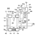
以上の説明では、高温再生器32A(図1参照)(変形例(図2参照)を含む)の上部管寄せ15の上端と第1気液分離器22の上端とがほぼ同じ高さになるように構成されているとしたが、以下の高温再生器32E(図4参照)のように構成されていてもよい。
図4は、本発明の第3の実施の形態に係る高温再生器32Eの縦断面図である。高温再生器32Eの、高温再生器32A(図1参照)と異なる点を以下に示す。高温再生器32Eは、第1気液分離器22の上端が上部管寄せ15の上端よりも高所に位置するように、第1気液分離器22及び上部管寄せ15が配設されている。そして、上部管寄せ15の上面に混合流体Fmを導出する混合流体導出口15eが形成されており、この混合流体導出口15eと第1の気液分離器22に形成された混合流体導入口22dとが90°曲がった混合流体管21Eで接続されている。これにより、混合流体導入口22d(少なくとも混合流体導入口22dの下端)が混合流体導出口15e(少なくとも混合流体導出口15eの下端)よりも高所に位置するようになっている。このように構成されていると、第1気液分離器22内における1次冷媒蒸気Vpが占める容積を増大させることができ、第1気液分離器22における気液分離効果を向上させることができる。この場合、混合流体管21の全体又は一部を大径にするもしくは複数本にする、あるいは上部管寄せ15の混合流体導出口15eと第1気液分離器22の混合流体導入口22dとを近接させて混合流体管21の長さを短くする等によって、液管10で発生した混合流体Fmが第1気液分離器22に導入される際の流通抵抗(圧力損失)を、第1気液分離器22への高温濃溶液Saの導入の妨げにならない程度に低減することにより、第1気液分離器22の高温濃溶液導出口22nから、常に、高温濃溶液Saを取り出すことができる。
In the above description, the upper end of the upper header 15 of the high temperature regenerator 32A (see FIG. 1) (including the modified example (see FIG. 2)) and the upper end of the first gas-liquid separator 22 are substantially the same height. However, the following high temperature regenerator 32E (see FIG. 4) may be used.
FIG. 4 is a longitudinal sectional view of a high temperature regenerator 32E according to the third embodiment of the present invention. Differences of the high temperature regenerator 32E from the high temperature regenerator 32A (see FIG. 1) will be described below. The high temperature regenerator 32E is provided with the first gas-liquid separator 22 and the upper header 15 so that the upper end of the first gas-liquid separator 22 is positioned higher than the upper end of the upper header 15. . A mixed fluid outlet 15e for leading the mixed fluid Fm is formed on the upper surface of the upper header 15, and the mixed fluid inlet 22d formed in the mixed fluid outlet 15e and the first gas-liquid separator 22 is formed. Are connected by a mixed fluid pipe 21E bent by 90 °. Thereby, the mixed fluid introduction port 22d (at least the lower end of the mixed fluid introduction port 22d) is positioned higher than the mixed fluid outlet 15e (at least the lower end of the mixed fluid outlet 15e). With this configuration, the volume occupied by the primary refrigerant vapor Vp in the first gas-liquid separator 22 can be increased, and the gas-liquid separation effect in the first gas-liquid separator 22 can be improved. it can. In this case, the whole or a part of the mixed fluid pipe 21 has a large diameter or a plurality of pipes, or the mixed fluid outlet 15e of the upper header 15 and the mixed fluid inlet 22d of the first gas-liquid separator 22 are provided. The flow resistance (pressure loss) when the mixed fluid Fm generated in the liquid pipe 10 is introduced into the first gas-liquid separator 22 by making the length of the mixed fluid pipe 21 close to each other is reduced. By reducing the temperature so as not to hinder the introduction of the hot concentrated solution Sa into the liquid separator 22, the hot concentrated solution Sa can always be taken out from the hot concentrated solution outlet 22n of the first gas-liquid separator 22. .

また、高温再生器32Eでは、第1気液分離器22と第2気液分離器24との位置関係が、外見上高温再生器32A(図1参照)と同様に示されているが、第2気液分離器24に形成された戻り溶液導出口24rは第2気液分離器24内の最下部である底面に設けられており、第2気液分離器24の最下部(すなわち戻り溶液導出口24r)が第1の気液分離器22内の高温濃溶液Saの常用液位SaLよりも高所に位置するように構成されている。このように構成されていると、第2気液分離器24内は、実質的に1次冷媒蒸気Vp(導出冷媒蒸気Va)で満たされることとなり、第2気液分離器24の内容積を小さくすることができる。常用液位SaLとして第1気液分離器22内に現れる高温濃溶液Saの最高液位を採用してもよく、この場合は、第2気液分離器24内は常に分離前後の1次冷媒蒸気Vpで満たされて十分に気液分離を行うことができる。また、常用液位SaLとして第1気液分離器22内に現れる高温濃溶液Saの最低液位を採用してもよく、この場合は、常用液位SaLを第1気液分離器22内に現れる高温濃溶液Saの最高液位とした場合に次ぐ気液分離性能になるが、高温再生器の全高を下げて高温再生器をコンパクトにすることができる。常用液位SaLとして第1気液分離器22内に現れる高温濃溶液Saの最高液位と最低液位との間の液位を採用すれば、両者の長所を按分することとなるため、常用液位SaLとして、典型的には主として運転される運転負荷時(例えば、運転時間が最も長くなる運転負荷時)における第1気液分離器22内の高温濃溶液Saの液位を採用すると、気液分離性能の向上と高温再生器32Eのコンパクト化とのバランスがよくなり好適である。吸収冷凍機30(図3参照)がどのような運転負荷で最も運転されるか、ひいては高温再生器32Eがどのような運転負荷で最も運転されるかは、高温再生器32Eが採用されるシステムの設計条件によるところが大きい。つまり、運転負荷範囲や第1気液分離器22及び第2気液分離器24の気液分離方式や気液分離効果を勘案して、第1気液分離器22の常用液位SaL(基準液面)を適宜決定するとよい。   Further, in the high temperature regenerator 32E, the positional relationship between the first gas-liquid separator 22 and the second gas-liquid separator 24 is shown in the same manner as the high temperature regenerator 32A (see FIG. 1). The return solution outlet 24r formed in the two gas-liquid separator 24 is provided at the bottom surface, which is the lowermost part in the second gas-liquid separator 24, and the lowermost part (that is, the return solution) of the second gas-liquid separator 24. The outlet 24r) is configured to be positioned higher than the normal liquid level SaL of the hot concentrated solution Sa in the first gas-liquid separator 22. If comprised in this way, the inside of the 2nd gas-liquid separator 24 will be substantially satisfy | filled with the primary refrigerant | coolant vapor | steam Vp (derived refrigerant | coolant vapor | steam Va), and the internal volume of the 2nd gas-liquid separator 24 will be filled. Can be small. The highest liquid level of the hot concentrated solution Sa appearing in the first gas-liquid separator 22 may be adopted as the common liquid level SaL. In this case, the first gas refrigerant in the second gas-liquid separator 24 is always before and after the separation. Gas-liquid separation can be sufficiently performed by being filled with the vapor Vp. Further, the lowest liquid level of the hot concentrated solution Sa appearing in the first gas-liquid separator 22 may be adopted as the common liquid level SaL. In this case, the common liquid level SaL is placed in the first gas-liquid separator 22. When the highest liquid level of the high-temperature concentrated solution Sa that appears, the gas-liquid separation performance is the next, but the total height of the high-temperature regenerator can be lowered to make the high-temperature regenerator compact. If the liquid level between the highest liquid level and the lowest liquid level of the hot concentrated solution Sa appearing in the first gas-liquid separator 22 as the common liquid level SaL is adopted, the advantages of both will be apportioned. As the liquid level SaL, typically, the liquid level of the hot concentrated solution Sa in the first gas-liquid separator 22 at the time of an operating load that is mainly operated (for example, at the time of the operating load with the longest operating time) is adopted. The balance between improvement of gas-liquid separation performance and compactness of the high-temperature regenerator 32E is improved, which is preferable. A system in which the high-temperature regenerator 32E is used to determine the operating load at which the absorption refrigerator 30 (see FIG. 3) is most operated and, in turn, the operating load at which the high-temperature regenerator 32E is most operated. The place depends on the design conditions. That is, taking into consideration the operating load range, the gas-liquid separation method of the first gas-liquid separator 22 and the second gas-liquid separator 24, and the gas-liquid separation effect, the normal liquid level SaL (reference) of the first gas-liquid separator 22 The liquid level may be appropriately determined.

前述のように、1次冷媒蒸気Vpが同伴する高温濃溶液Saである戻り溶液Srは、第1気液分離器22内で冷媒蒸気から一度分離されているために、上部管寄せ15から第1気液分離器22へ流れる混合流体Fmに含まれる高温濃溶液Saよりもはるかに少ない。また、第2気液分離器24には第1気液分離器22と連通した戻り溶液Sr(高温濃溶液Sa)の液位が現れる。高温再生器32Eでは、第2気液分離器24の最下部が第1の気液分離器22内の高温濃溶液Saの常用液位SaLよりも高所に位置し、第2気液分離器24の最下部に戻り溶液導出口24rが形成されているので、第2気液分離器24内に流入する戻り溶液Srの量が少ないことと1次冷媒蒸気Vp(導出冷媒蒸気Va)で満たされた第2気液分離器24内すべての空間を利用して、第2気液分離器24に流入した、戻り溶液Srが同伴した1次冷媒蒸気Vpから、戻り溶液Srを十分に(導出冷媒蒸気導出口24eから導出される導出冷媒蒸気Vaが、高温再生器32Eが吸収冷凍機30(図3参照)に組み込まれたときの吸収冷凍機30の作動に支障がない程度に)分離することができる。運転負荷が低い場合には、第1気液分離器22から第2気液分離器24に同伴する戻り溶液Srは少ないために、この傾向はより顕著になる。このため、運転負荷が高い場合でも低い場合でも、第2気液分離器24の導出冷媒蒸気導出口24eから、常に、高温冷媒蒸気Vaを取り出すことができる。   As described above, the return solution Sr, which is the high-temperature concentrated solution Sa accompanied by the primary refrigerant vapor Vp, is once separated from the refrigerant vapor in the first gas-liquid separator 22, so It is far less than the hot concentrated solution Sa contained in the mixed fluid Fm flowing to the one gas-liquid separator 22. Further, the liquid level of the return solution Sr (high-temperature concentrated solution Sa) communicating with the first gas-liquid separator 22 appears in the second gas-liquid separator 24. In the high temperature regenerator 32E, the lowermost part of the second gas-liquid separator 24 is located higher than the normal liquid level SaL of the hot concentrated solution Sa in the first gas-liquid separator 22, and the second gas-liquid separator Since the return solution outlet 24r is formed at the lowermost part of 24, the amount of the return solution Sr flowing into the second gas-liquid separator 24 is small and it is filled with the primary refrigerant vapor Vp (derived refrigerant vapor Va). Using the entire space in the second gas-liquid separator 24, the return solution Sr is sufficiently (derived) from the primary refrigerant vapor Vp that has flowed into the second gas-liquid separator 24 and accompanied by the return solution Sr. The derived refrigerant vapor Va derived from the refrigerant vapor outlet 24e is separated (to the extent that there is no hindrance to the operation of the absorption refrigerator 30 when the high-temperature regenerator 32E is incorporated in the absorption refrigerator 30 (see FIG. 3)). be able to. When the operating load is low, this tendency becomes more prominent because the return solution Sr accompanying the first gas-liquid separator 22 to the second gas-liquid separator 24 is small. For this reason, it is possible to always take out the high-temperature refrigerant vapor Va from the derived refrigerant vapor outlet 24e of the second gas-liquid separator 24 regardless of whether the operation load is high or low.

なお、図5で本発明の第4の実施の形態に係る高温再生器32Fとして示すように、第1の気液分離器22の上端が、上部管寄せ15の上端よりも高所に位置するようにしつつ(図5では第1気液分離器22の混合流体導入口22dも上部管寄せ15の混合流体導出口15eよりも高所に位置するようになっている)、第2気液分離器24の導出冷媒蒸気導出口24eが第1気液分離器22の1次冷媒蒸気導出口22eとほぼ同じ高さに位置するように配設して、高温再生器32Fの高さを抑制するように構成されていてもよい。導出冷媒蒸気導出口24eが1次冷媒蒸気導出口22eとほぼ同じ高さに位置し、第1気液分離器22の上端が上部管寄せ15の上端よりも高所に位置していると、第1気液分離器22内における1次冷媒蒸気Vpが占める容積を確保することが可能となり、第1の気液分離器22における気液分離効果を向上させることができる。
また、高温再生器32E(図4参照)及び高温再生器32F(図5参照)共に、第2の戻り管26の他端を第1の戻り管25に割り込ませ、戻り溶液Srを第1の戻り管25内を流れる高温濃溶液Saに合流させるように図示したが、図1に示す高温再生器32Aのように、第1の戻り管25と第2の戻り管26とが共に下部管寄せ14に接続されるように構成されていてもよい。
Note that, as shown in FIG. 5 as a high temperature regenerator 32F according to the fourth embodiment of the present invention, the upper end of the first gas-liquid separator 22 is located higher than the upper end of the upper header 15. In this manner (in FIG. 5, the mixed fluid inlet 22d of the first gas-liquid separator 22 is also positioned higher than the mixed fluid outlet 15e of the upper header 15), while the second gas-liquid separation is performed. The outlet refrigerant vapor outlet 24e of the regenerator 24 is disposed so as to be located at substantially the same height as the primary refrigerant vapor outlet 22e of the first gas-liquid separator 22 to suppress the height of the high temperature regenerator 32F. It may be configured as follows. When the outlet refrigerant vapor outlet 24e is located at substantially the same height as the primary refrigerant vapor outlet 22e, and the upper end of the first gas-liquid separator 22 is located higher than the upper end of the upper header 15, The volume occupied by the primary refrigerant vapor Vp in the first gas-liquid separator 22 can be secured, and the gas-liquid separation effect in the first gas-liquid separator 22 can be improved.
Further, in both the high temperature regenerator 32E (see FIG. 4) and the high temperature regenerator 32F (see FIG. 5), the other end of the second return pipe 26 is interrupted into the first return pipe 25, and the return solution Sr is supplied to the first return pipe S1. Although illustrated so as to be merged with the hot concentrated solution Sa flowing in the return pipe 25, the first return pipe 25 and the second return pipe 26 are both the lower header as in the high temperature regenerator 32A shown in FIG. 14 may be connected.

以上の説明では、高温再生器32A(図1参照)(変形例(図2参照)を含む)、32E(図4参照)、32F(図5参照)の第1気液分離器22及び第2気液分離器24が、共に垂直のバッフル板22a、24aを内蔵した気液分離方式であるとしたが、これに限らず、図6に示す遠心式気液分離方式やその他の気液分離方式でもよい。
図6は、高温再生器32A(変形例(図2参照)を含む)、32E、32Fが有する気液分離器の変形例を説明する図であり、(a)は水平断面図、(b)は縦断面図である。ここでは第1気液分離器22(図1等参照)の変形例として説明し、第2気液分離器24(図1等参照)については対応する部材の符号を図6中に括弧書きで示す。変形例に係る気液分離器22Cは、バッフル板22a(図1等参照)に代えて蒸気導出管22pが設けられている。蒸気導出管22pは、一端が気液分離器22Cの上面に形成された1次冷媒蒸気導出口22eに接続されており、他端が気液分離器22C内に貯留される高温濃溶液Saの最高液位よりも上方に位置するように配設されている。蒸気導出管22pが気液分離器22C内に延びている場合であっても、蒸気導出管22pと1次冷媒蒸気管23との接続位置を気液分離器22Cの蒸気取り出し口の位置とする。このように構成された気液分離器22Cでは、混合流体管21を介して導入された混合流体Fmが蒸気導出管22pの外周に沿って旋回しながら下降し、1次冷媒蒸気Vpと高温濃溶液Saとに分離される。そして、1次冷媒蒸気Vpは蒸気導出管22pの内部を通って1次冷媒蒸気導出口22eから導出され、高温濃溶液Saは高温濃溶液管46あるいは第1の戻り管25(図1等参照)に導出される。
In the above description, the first gas-liquid separator 22 and the second high-temperature regenerator 32A (see FIG. 1) (including the modified example (see FIG. 2)), 32E (see FIG. 4), and 32F (see FIG. 5). The gas-liquid separator 24 is a gas-liquid separation system in which both vertical baffle plates 22a and 24a are built. However, the present invention is not limited to this, and the centrifugal gas-liquid separation system and other gas-liquid separation systems shown in FIG. But you can.
FIG. 6 is a diagram for explaining a modification of the gas-liquid separator included in the high temperature regenerator 32A (including a modification (see FIG. 2)), 32E, 32F, (a) is a horizontal sectional view, (b). Is a longitudinal sectional view. Here, the first gas-liquid separator 22 (see FIG. 1 and the like) will be described as a modified example, and for the second gas-liquid separator 24 (see FIG. 1 and the like), the reference numerals of the corresponding members are shown in parentheses in FIG. Show. The gas-liquid separator 22C according to the modified example is provided with a steam outlet pipe 22p instead of the baffle plate 22a (see FIG. 1 and the like). One end of the vapor outlet pipe 22p is connected to a primary refrigerant vapor outlet 22e formed on the upper surface of the gas-liquid separator 22C, and the other end of the high-temperature concentrated solution Sa stored in the gas-liquid separator 22C. It arrange | positions so that it may be located above a highest liquid level. Even when the vapor outlet pipe 22p extends into the gas-liquid separator 22C, the connection position of the vapor outlet pipe 22p and the primary refrigerant vapor pipe 23 is the position of the vapor outlet of the gas-liquid separator 22C. . In the gas-liquid separator 22C configured as described above, the mixed fluid Fm introduced through the mixed fluid pipe 21 descends while swirling along the outer periphery of the vapor outlet pipe 22p, and the primary refrigerant vapor Vp and the high temperature concentration Separated into solution Sa. The primary refrigerant vapor Vp is led out from the primary refrigerant vapor outlet 22e through the inside of the vapor outlet pipe 22p, and the high temperature concentrated solution Sa is the high temperature concentrated solution pipe 46 or the first return pipe 25 (see FIG. 1 and the like). ).

バッフル板を内蔵した気液分離方式及び遠心式気液分離方式にはそれぞれ気液分離性能が優れている運転負荷領域があるので、気液分離性能が優れている運転負荷領域が異なる2個の気液分離器を、それぞれ第1気液分離器及び第2気液分離器として組み合わせてもよい。例えば、高温再生器に流入する溶液流量、高温再生器の運転圧力、運転負荷範囲の広狭等に応じて、バッフル板を内蔵した気液分離器、遠心式気液分離器、あるいは他の方式の気液分離器のうちの1つを第1気液分離器とし、第1の気液分離器と異なる方式の気液分離器を第2気液分離器として採用してもよい。また、第1及び第2の気液分離器として同じ気液分離器方式を採用した場合であっても、気液分離器の寸法を変えることによって気液分離に優れた運転負荷領域を変えることができるので、寸法の異なる2個の気液分離器を合わせて高温再生器を構成してもよい。このように構成することにより、広い運転負荷範囲で優れた気液分離性能を発揮する気液分離器を備えた高温再生器とすることができる。   Since the gas-liquid separation method with built-in baffle plate and the centrifugal gas-liquid separation method each have an operational load region with excellent gas-liquid separation performance, two operational load regions with excellent gas-liquid separation performance are different. The gas-liquid separator may be combined as a first gas-liquid separator and a second gas-liquid separator, respectively. For example, depending on the flow rate of the solution flowing into the high-temperature regenerator, the operating pressure of the high-temperature regenerator, the range of the operating load range, etc., a gas-liquid separator with a built-in baffle plate, a centrifugal gas-liquid separator, or other methods One of the gas-liquid separators may be used as the first gas-liquid separator, and a gas-liquid separator of a different system from the first gas-liquid separator may be used as the second gas-liquid separator. Moreover, even when the same gas-liquid separator system is adopted as the first and second gas-liquid separators, the operating load region excellent in gas-liquid separation can be changed by changing the dimensions of the gas-liquid separator. Therefore, a high-temperature regenerator may be configured by combining two gas-liquid separators having different dimensions. By comprising in this way, it can be set as the high temperature regenerator provided with the gas-liquid separator which exhibits the outstanding gas-liquid separation performance in the wide driving | running load range.

以上の説明では、上部管寄せ15と第1気液分離器22とが1本の混合流体管21(図1、図2参照)、21E(図4、図5参照)で接続されているように示されているが、2本以上の混合流体管21、21Eで接続されていてもよい。
また、環状の上部管寄せ及び下部管寄せを採用した例を示したが、水平断面が矩形形状の上部管寄せ及び下部管寄せを採用した角形貫流ボイラ式高温再生器に適用してもよい。
In the above description, the upper header 15 and the first gas-liquid separator 22 are connected by a single mixed fluid pipe 21 (see FIGS. 1 and 2) and 21E (see FIGS. 4 and 5). However, it may be connected by two or more mixed fluid pipes 21 and 21E.
Moreover, although the example which employ | adopted the cyclic | annular upper header and the lower header was shown, you may apply to the square cross-flow boiler type | mold high temperature regenerator which employ | adopted the upper header and the lower header whose horizontal cross section is a rectangular shape.

以上の説明では、吸収冷凍機30が三重効用吸収冷凍機であるとして説明したが、単効用吸収冷凍機や二重効用吸収冷凍機であってもよい。単効用吸収冷凍機とした場合は、本実施の形態で説明した高温再生器32A(変形例(図2参照)を含む)、32E、32Fを再生器とすることができ、二重効用吸収冷凍機とした場合は、本実施の形態で説明した高温再生器32A(変形例(図2参照)を含む)、32E、32Fを作動温度が高い方の再生器とするとよい。   In the above description, the absorption refrigerator 30 is described as being a triple effect absorption refrigerator, but may be a single effect absorption refrigerator or a double effect absorption refrigerator. In the case of a single-effect absorption refrigerator, the high-temperature regenerator 32A (including the modified example (see FIG. 2)), 32E, and 32F described in the present embodiment can be used as a regenerator. In the case of a machine, the high-temperature regenerator 32A (including the modified example (see FIG. 2)) 32E and 32F described in the present embodiment may be used as a regenerator with a higher operating temperature.

以上の説明では、吸収冷凍機30が高温再生器32A(変形例(図2参照)を含む)、32E、32Fの下部管寄せ14に希溶液Swを導入するように構成されることとしたが、低温濃溶液Sbや中温濃溶液Smを下部管寄せ14に導入するように構成してもよい。   In the above description, the absorption refrigerator 30 is configured to introduce the dilute solution Sw into the lower header 14 of the high-temperature regenerator 32A (including the modified example (see FIG. 2)), 32E, and 32F. Alternatively, the low temperature concentrated solution Sb and the medium temperature concentrated solution Sm may be introduced into the lower header 14.

本発明の第1の実施の形態に係る高温再生器の縦断面図である。1 is a longitudinal sectional view of a high temperature regenerator according to a first embodiment of the present invention. 本発明の第1の実施の形態に係る高温再生器の変形例の縦断面図である。It is a longitudinal cross-sectional view of the modification of the high temperature regenerator which concerns on the 1st Embodiment of this invention. 本発明の第2の実施の形態に係る吸収冷凍機の系統図である。It is a systematic diagram of the absorption refrigerator which concerns on the 2nd Embodiment of this invention. 本発明の第3の実施の形態に係る高温再生器の縦断面図である。It is a longitudinal cross-sectional view of the high temperature regenerator which concerns on the 3rd Embodiment of this invention. 本発明の第4の実施の形態に係る高温再生器の縦断面図である。It is a longitudinal cross-sectional view of the high temperature regenerator which concerns on the 4th Embodiment of this invention. 高温再生器が有する気液分離器の変形例を説明する図である。(a)は水平断面図、(b)は縦断面図である。It is a figure explaining the modification of the gas-liquid separator which a high temperature regenerator has. (A) is a horizontal sectional view, (b) is a longitudinal sectional view. 従来の貫流ボイラ式高温再生器の縦断面図である。It is a longitudinal cross-sectional view of the conventional once-through boiler type high temperature regenerator.

符号の説明Explanation of symbols

10 液管
14 下部管寄せ(液室)
15 上部管寄せ(上部環状部材)
15e 混合流体導出口
22 第1の気液分離器
22d 混合流体導入口
22e 1次冷媒蒸気導出口
22n 濃溶液導出口
24 第2の気液分離器
24e 導出冷媒蒸気導出口
24r 戻り溶液導出口
25 第1の戻り管
26 第2の戻り管
31 吸収器
32A、32E、32F 高温再生器
32M 中温再生器
32B 低温再生器
33 凝縮器
34 蒸発器
Fm 混合流体
p 被冷却媒体
Sa 高温濃溶液
SaL 常用液位
Sd 濃溶液
Sr 戻り溶液
Sw 希溶液
Va 高温濃溶液(導出冷媒蒸気)
Ve 冷媒
Vf 冷媒液
Vp 1次冷媒蒸気
10 Liquid tube 14 Lower header (Liquid chamber)
15 Upper header (upper ring member)
15e Mixed fluid outlet 22 First gas-liquid separator 22d Mixed fluid inlet 22e Primary refrigerant vapor outlet 22n Concentrated solution outlet 24 Second gas-liquid separator 24e Outlet refrigerant vapor outlet 24r Return solution outlet 25 First return pipe 26 Second return pipe 31 Absorbers 32A, 32E, 32F High temperature regenerator 32M Medium temperature regenerator 32B Low temperature regenerator 33 Condenser 34 Evaporator Fm Mixed fluid p Medium to be cooled Sa High temperature concentrated solution SaL Regular liquid Position Sd Concentrated solution Sr Returned solution Sw Dilute solution Va Hot concentrated solution (derived refrigerant vapor)
Ve Refrigerant Vf Refrigerant liquid Vp Primary refrigerant vapor

Claims (6)

加熱され濃縮される希溶液を下方から上方に向かって流す液管と;
前記液管に、前記液管の下部から前記希溶液を供給する液室と;
前記液管で前記希溶液が加熱されることによって発生した1次冷媒蒸気と濃度が上昇した濃溶液との混合流体を導入し、前記混合流体から前記1次冷媒蒸気と前記濃溶液とを分離する、前記液室と連通する第1の気液分離器であって、前記混合流体から前記1次冷媒蒸気と前記濃溶液とを分離する第1のバッフル板が前記第1の気液分離器の上部を2分割するように前記第1の気液分離器の天板に取り付けられると共に前記第1の気液分離器の底面又は下部側面に前記濃溶液を吸収冷凍機の吸収器に向けて導出する濃溶液導出口が形成されて構成された第1の気液分離器と;
前記1次冷媒蒸気を導入し、前記1次冷媒蒸気に同伴する、前記希溶液よりも高濃度の溶液である戻り溶液と、導出冷媒蒸気とに分離する第2の気液分離器であって、前記1次冷媒蒸気から前記戻り溶液を分離する第2のバッフル板が前記第2の気液分離器の上部を2分割するように前記第2の気液分離器の上面に取り付けられて構成された第2の気液分離器とを備え;
前記第2の気液分離器が、前記第1の気液分離器よりも小さい内容積とすることにより前記第1の気液分離器における気液分離性能上の運転負荷領域とは異なる気液分離性能上の運転負荷領域を有するように構成され;
前記第1の気液分離器内の濃溶液を前記液室に導く第1の戻り管と;
前記戻り溶液を前記液室に導く第2の戻り管とを備え;
前記第2の気液分離器の最下部に前記戻り溶液を前記液室に向けて導出する戻り溶液導出口が形成され、前記戻り溶液導出口よりも高所の前記第2の気液分離器に前記導出冷媒蒸気を導出する導出冷媒蒸気導出口が形成され;
前記戻り溶液導出口が形成された前記最下部が、前記第1の気液分離器内の濃溶液の常用液位よりも高所に位置するように構成された;
高温再生器。
A liquid tube for flowing a heated and concentrated dilute solution from below to above;
A liquid chamber for supplying the dilute solution to the liquid pipe from a lower part of the liquid pipe;
A mixed fluid of a primary refrigerant vapor generated by heating the dilute solution in the liquid pipe and a concentrated solution having an increased concentration is introduced, and the primary refrigerant vapor and the concentrated solution are separated from the mixed fluid. A first gas-liquid separator that communicates with the liquid chamber, wherein a first baffle plate that separates the primary refrigerant vapor and the concentrated solution from the mixed fluid is the first gas-liquid separator. The upper part of the first gas-liquid separator is attached to the top plate of the first gas-liquid separator and the concentrated solution is directed to the absorber of the absorption refrigerator on the bottom or lower side surface of the first gas-liquid separator. A first gas-liquid separator configured to be formed with a concentrated solution outlet for outlet ;
Introducing the primary refrigerant vapor, entrained in the primary refrigerant vapor, and returning the solution is a solution of higher concentration than the rare solution, a second gas-liquid separator for separating the outlet refrigerant vapor A second baffle plate for separating the return solution from the primary refrigerant vapor is attached to the upper surface of the second gas-liquid separator so as to divide the upper part of the second gas-liquid separator into two. A second gas-liquid separator configured ;
The second gas-liquid separator is different liquid from the first gas-liquid operating load range on the gas-liquid separation performance in the first gas-liquid separator by a small internal volume than the separator Configured to have an operating load range on separation performance ;
A first return pipe for guiding the concentrated solution in the first gas-liquid separator to the liquid chamber;
E Bei a second return pipe leading to the return solution into the liquid chamber;
A return solution outlet for leading the return solution toward the liquid chamber is formed at the lowermost part of the second gas-liquid separator, and the second gas-liquid separator is higher than the return solution outlet. A lead-out refrigerant vapor outlet for leading out the lead-out refrigerant vapor is formed in
The lowermost portion where the return solution outlet is formed is configured to be positioned higher than the normal liquid level of the concentrated solution in the first gas-liquid separator;
High temperature regenerator.
前記戻り溶液が前記第1の戻り管を経由して前記液室に導かれるように構成された;
請求項に記載の高温再生器。
The return solution is configured to be guided to the liquid chamber via the first return pipe;
The high temperature regenerator according to claim 1 .
記濃溶液導出口が、作動中における前記液管に現れる液面の最低高さと、前記液管の上端の高さとの間の高さに位置するように構成された;
請求項1又は請求項に記載の高温再生器。
Before Kiko solution outlet comprises a minimum height of the liquid level appearing in the liquid pipe during operation, it is configured to be positioned at a height between the height of the upper end of the liquid pipe;
The high temperature regenerator according to claim 1 or 2 .
前記液管を複数備え;
さらに、複数の前記液管から前記混合流体を収集する上部環状部材を備え;
前記液室が、複数の前記液管に前記希溶液を供給するように構成された;
請求項1乃至請求項のいずれか1項に記載の高温再生器。
A plurality of the liquid tubes;
And an upper annular member for collecting the mixed fluid from the plurality of liquid tubes;
The liquid chamber is configured to supply the dilute solution to a plurality of the liquid tubes;
The high temperature regenerator according to any one of claims 1 to 3 .
前記第1の気液分離器の上端が、前記上部環状部材の上端よりも高所に位置するように構成された;
請求項に記載の高温再生器。
An upper end of the first gas-liquid separator is configured to be higher than an upper end of the upper annular member;
The high temperature regenerator according to claim 4 .
請求項1乃至請求項のいずれか1項に記載の高温再生器と;
冷媒蒸気を凝縮する凝縮器と;
前記凝縮器で凝縮した冷媒液を導入し被冷却媒体の熱で前記冷媒液を蒸発させる蒸発器と;
前記濃溶液を導入し、前記蒸発器で蒸発した冷媒を前記濃溶液で吸収し濃度が低下した希溶液を前記液室に向けて導出する吸収器とを備える;
吸収冷凍機。
A high-temperature regenerator according to any one of claims 1 to 5 ;
A condenser that condenses the refrigerant vapor;
An evaporator that introduces the refrigerant liquid condensed in the condenser and evaporates the refrigerant liquid with heat of a medium to be cooled;
An absorber that introduces the concentrated solution, absorbs the refrigerant evaporated in the evaporator with the concentrated solution, and guides the diluted solution having a reduced concentration toward the liquid chamber;
Absorption refrigerator.
JP2007147397A 2006-06-02 2007-06-01 High temperature regenerator and absorption refrigerator Expired - Fee Related JP5259124B2 (en)

Priority Applications (1)

Application Number Priority Date Filing Date Title
JP2007147397A JP5259124B2 (en) 2006-06-02 2007-06-01 High temperature regenerator and absorption refrigerator

Applications Claiming Priority (3)

Application Number Priority Date Filing Date Title
JP2006155230 2006-06-02
JP2007147397A JP5259124B2 (en) 2006-06-02 2007-06-01 High temperature regenerator and absorption refrigerator

Publications (2)

Publication Number Publication Date
JP2008008608A JP2008008608A (en) 2008-01-17
JP5259124B2 true JP5259124B2 (en) 2013-08-07

Family

ID=39066975

Family Applications (1)

Application Number Title Priority Date Filing Date
JP2007147397A Expired - Fee Related JP5259124B2 (en) 2006-06-02 2007-06-01 High temperature regenerator and absorption refrigerator

Country Status (1)

Country Link
JP (1) JP5259124B2 (en)

Cited By (1)

* Cited by examiner, † Cited by third party
Publication number Priority date Publication date Assignee Title
KR102038436B1 (en) * 2018-09-14 2019-11-26 삼중테크 주식회사 A high temperature generator module and a triple effect absorption chiller with a gas burner having the same module

Family Cites Families (5)

* Cited by examiner, † Cited by third party
Publication number Priority date Publication date Assignee Title
JPS6060472A (en) * 1983-09-14 1985-04-08 株式会社日立製作所 Regenerator for absorption type refrigerator
JP3943672B2 (en) * 1997-09-20 2007-07-11 パロマ工業株式会社 Absorption refrigerator
JP3318302B2 (en) * 2000-01-18 2002-08-26 川重冷熱工業株式会社 Absorbent liquid concentrator and absorption refrigerator using the same
JP2004053085A (en) * 2002-07-18 2004-02-19 Daikin Ind Ltd Triple effect absorption refrigeration system
JP3929864B2 (en) * 2002-09-26 2007-06-13 大阪瓦斯株式会社 Absorption refrigeration equipment high temperature regenerator

Cited By (1)

* Cited by examiner, † Cited by third party
Publication number Priority date Publication date Assignee Title
KR102038436B1 (en) * 2018-09-14 2019-11-26 삼중테크 주식회사 A high temperature generator module and a triple effect absorption chiller with a gas burner having the same module

Also Published As

Publication number Publication date
JP2008008608A (en) 2008-01-17

Similar Documents

Publication Publication Date Title
JP5261073B2 (en) Gas-liquid separator, high-temperature regenerator, absorption refrigerator, and absorption heat pump
KR101947679B1 (en) High-efficient two stage absorption refrigerator of low temperature water with increased efficiency by two stage separated heat exchange method
JP5259124B2 (en) High temperature regenerator and absorption refrigerator
JP2008064422A (en) High temperature regenerator and absorption refrigerating machine
JP4701147B2 (en) 2-stage absorption refrigerator
KR910006217B1 (en) Dual-effect air-cooled freezer
JP4519744B2 (en) High temperature regenerator and absorption refrigerator
JP2009299936A (en) Absorption refrigerating machine
JP2014199150A (en) Absorption type heat source device
JP5037987B2 (en) High temperature regenerator and absorption refrigerator
JP5148264B2 (en) High temperature regenerator and absorption refrigerator
JP5536855B2 (en) Absorption refrigerator
CN208296358U (en) Absorption Refrigerator
JP5331232B2 (en) Regenerator and absorption refrigerator
JP5053148B2 (en) High temperature regenerator
JP2007263411A (en) Absorption refrigerator
JPS6133483Y2 (en)
JP2007071475A (en) Triple-effect absorption refrigerating machine
JP5499139B2 (en) Absorption refrigerator
JP4843281B2 (en) High temperature regenerator and absorption refrigerator
JP2993454B2 (en) Air-cooled absorption refrigeration system
JP2007232271A (en) Triple effect absorption refrigerating machine
JP3938712B2 (en) High-temperature regenerator and absorption chiller / heater
JP2017166804A (en) Absorption heat pump
JP6337055B2 (en) Absorption heat pump

Legal Events

Date Code Title Description
A621 Written request for application examination

Free format text: JAPANESE INTERMEDIATE CODE: A621

Effective date: 20100413

A977 Report on retrieval

Free format text: JAPANESE INTERMEDIATE CODE: A971007

Effective date: 20120125

A131 Notification of reasons for refusal

Free format text: JAPANESE INTERMEDIATE CODE: A131

Effective date: 20120207

A521 Written amendment

Free format text: JAPANESE INTERMEDIATE CODE: A523

Effective date: 20120406

A02 Decision of refusal

Free format text: JAPANESE INTERMEDIATE CODE: A02

Effective date: 20121030

A521 Written amendment

Free format text: JAPANESE INTERMEDIATE CODE: A523

Effective date: 20130124

A911 Transfer of reconsideration by examiner before appeal (zenchi)

Free format text: JAPANESE INTERMEDIATE CODE: A911

Effective date: 20130201

TRDD Decision of grant or rejection written
A01 Written decision to grant a patent or to grant a registration (utility model)

Free format text: JAPANESE INTERMEDIATE CODE: A01

Effective date: 20130416

A61 First payment of annual fees (during grant procedure)

Free format text: JAPANESE INTERMEDIATE CODE: A61

Effective date: 20130424

FPAY Renewal fee payment (event date is renewal date of database)

Free format text: PAYMENT UNTIL: 20160502

Year of fee payment: 3

R150 Certificate of patent or registration of utility model

Ref document number: 5259124

Country of ref document: JP

Free format text: JAPANESE INTERMEDIATE CODE: R150

Free format text: JAPANESE INTERMEDIATE CODE: R150

R250 Receipt of annual fees

Free format text: JAPANESE INTERMEDIATE CODE: R250

R250 Receipt of annual fees

Free format text: JAPANESE INTERMEDIATE CODE: R250

R250 Receipt of annual fees

Free format text: JAPANESE INTERMEDIATE CODE: R250

R250 Receipt of annual fees

Free format text: JAPANESE INTERMEDIATE CODE: R250

LAPS Cancellation because of no payment of annual fees