JP5259019B2 - Motor grader - Google Patents
Motor grader Download PDFInfo
- Publication number
- JP5259019B2 JP5259019B2 JP2012527557A JP2012527557A JP5259019B2 JP 5259019 B2 JP5259019 B2 JP 5259019B2 JP 2012527557 A JP2012527557 A JP 2012527557A JP 2012527557 A JP2012527557 A JP 2012527557A JP 5259019 B2 JP5259019 B2 JP 5259019B2
- Authority
- JP
- Japan
- Prior art keywords
- plate
- leg
- frame
- motor grader
- annular portion
- Prior art date
- Legal status (The legal status is an assumption and is not a legal conclusion. Google has not performed a legal analysis and makes no representation as to the accuracy of the status listed.)
- Expired - Fee Related
Links
Images
Classifications
-
- E—FIXED CONSTRUCTIONS
- E02—HYDRAULIC ENGINEERING; FOUNDATIONS; SOIL SHIFTING
- E02F—DREDGING; SOIL-SHIFTING
- E02F3/00—Dredgers; Soil-shifting machines
- E02F3/04—Dredgers; Soil-shifting machines mechanically-driven
- E02F3/76—Graders, bulldozers, or the like with scraper plates or ploughshare-like elements; Levelling scarifying devices
- E02F3/7636—Graders with the scraper blade mounted under the tractor chassis
- E02F3/7645—Graders with the scraper blade mounted under the tractor chassis with the scraper blade being pivotable about a horizontal axis disposed parallel to the blade
-
- E—FIXED CONSTRUCTIONS
- E02—HYDRAULIC ENGINEERING; FOUNDATIONS; SOIL SHIFTING
- E02F—DREDGING; SOIL-SHIFTING
- E02F3/00—Dredgers; Soil-shifting machines
- E02F3/04—Dredgers; Soil-shifting machines mechanically-driven
- E02F3/76—Graders, bulldozers, or the like with scraper plates or ploughshare-like elements; Levelling scarifying devices
- E02F3/7636—Graders with the scraper blade mounted under the tractor chassis
-
- E—FIXED CONSTRUCTIONS
- E02—HYDRAULIC ENGINEERING; FOUNDATIONS; SOIL SHIFTING
- E02F—DREDGING; SOIL-SHIFTING
- E02F3/00—Dredgers; Soil-shifting machines
- E02F3/04—Dredgers; Soil-shifting machines mechanically-driven
- E02F3/76—Graders, bulldozers, or the like with scraper plates or ploughshare-like elements; Levelling scarifying devices
- E02F3/80—Component parts
- E02F3/84—Drives or control devices therefor, e.g. hydraulic drive systems
- E02F3/844—Drives or control devices therefor, e.g. hydraulic drive systems for positioning the blade, e.g. hydraulically
Landscapes
- Engineering & Computer Science (AREA)
- Mechanical Engineering (AREA)
- Mining & Mineral Resources (AREA)
- Civil Engineering (AREA)
- General Engineering & Computer Science (AREA)
- Structural Engineering (AREA)
- Body Structure For Vehicles (AREA)
Description
本発明は、作業機を備えるモータグレーダに関する。 The present invention relates to a motor grader including a work machine.
一般的に、モータグレーダは、フレームと、フレームの下方に配置される作業機と、フレームに取り付けられる環状のリフタガイドと、リフタガイドと作業機とに連結されるリフトシリンダと、を備えている(例えば、特許文献1参照)。 In general, a motor grader includes a frame, a working machine disposed below the frame, an annular lifter guide attached to the frame, and a lift cylinder coupled to the lifter guide and the working machine. (For example, refer to Patent Document 1).
(発明が解決しようとする課題)
ところで、近年、作業量を増大するためにタイヤ幅を広くしたり、アクスル及びリアフレームなどの強度を増強したりすることに伴って、モータグレーダの車重が重くなる傾向にある。そのため、側溝を掘るために作業機を大きく傾けて車重を作業機に掛けた場合に、重くなった車重がリフトシリンダを介してリフタガイドに掛かることによって、リフタガイドとフレームとの接合部の耐久性が低下するおそれがある。(Problems to be solved by the invention)
By the way, in recent years, the vehicle weight of a motor grader tends to increase as the tire width is increased in order to increase the amount of work and the strength of the axle and rear frame is increased. Therefore, when the work implement is tilted greatly to dig a side groove and the vehicle weight is applied to the work implement, the heavy vehicle weight is applied to the lifter guide via the lift cylinder, so that the joint between the lifter guide and the frame There is a risk that the durability of the material may be reduced.
本発明は、上述の状況に鑑みてなされたものであり、リフタガイドとフレームとの接合強度を向上可能なモータグレーダを提供することを目的とする。 The present invention has been made in view of the above-described situation, and an object thereof is to provide a motor grader capable of improving the bonding strength between the lifter guide and the frame.
(課題を解決するための手段)
本発明の第1の態様に係るモータグレーダは、フレームと、フレームの下方に配置される作業機と、フレームを取り囲み、フレームに接合されるリフタガイドと、リフタガイドを取り囲むリフタブラケットと、リフタブラケットに取り付けられ、作業機を駆動するためのリフトシリンダと、を備える。リフタガイドは、フレームの外周を取り囲む環状部と、環状部の内周に連なるとともに側面視において環状部から突出しており、外縁をフレームに接合される第1脚部と、を有する。(Means for solving the problem)
A motor grader according to a first aspect of the present invention includes a frame, a working machine disposed below the frame, a lifter guide that surrounds the frame and is joined to the frame, a lifter bracket that surrounds the lifter guide, and a lifter bracket. And a lift cylinder for driving the work machine. The lifter guide has an annular portion that surrounds the outer periphery of the frame, and a first leg portion that is continuous with the inner periphery of the annular portion and projects from the annular portion in a side view, and has an outer edge joined to the frame.
本発明の第1の態様に係るモータグレーダによれば、リフタガイドが第1脚部を有しているので、フレームとリフタガイドとの接合範囲(すなわち、溶接線長さ)を大きくすることができる。そのため、リフタガイドとフレームとの接合強度を向上させることができる。 According to the motor grader according to the first aspect of the present invention, since the lifter guide has the first leg portion, it is possible to increase the joining range (that is, the weld line length) between the frame and the lifter guide. it can. Therefore, the joint strength between the lifter guide and the frame can be improved.
本発明の第2の態様に係るモータグレーダは、第1の態様に係り、フレームは、車幅方向に延びる上板と、上板に対向する下板と、上下方向に延び、上板と下板に挟まれる第1側板と、第1側板に対向し、上板と下板に挟まれる第2側板と、によって構成される。フレームのうちリフタガイドが接合される接合部分において、上板および下板それぞれの車幅方向両端の幅は、第1側板および第2側板の車幅方向両端の幅と同等である。第1脚部の外縁は、上板の側面と、第1側板の側面と、下板の側面とに接合されている。 A motor grader according to a second aspect of the present invention relates to the first aspect, wherein the frame extends in the vehicle width direction, a lower plate facing the upper plate, and extends in the vertical direction. The first side plate is sandwiched between plates, and the second side plate is opposed to the first side plate and sandwiched between the upper plate and the lower plate. In the joint portion of the frame where the lifter guide is joined, the widths of both the upper and lower plates in the vehicle width direction are equal to the widths of the first side plate and the second side plate in the vehicle width direction. The outer edge of the first leg is joined to the side surface of the upper plate, the side surface of the first side plate, and the side surface of the lower plate.
本発明の第2の態様に係るモータグレーダによれば、上板および下板の幅と第1側板と第2側板との幅とを同等にすることによって、第1脚部を上板および下板に接合することが実現されている。その結果、フレームとリフタガイドとの接合範囲をさらに大きくできるので、リフタガイドとフレームとの接合強度をさらに向上させることができる。 According to the motor grader according to the second aspect of the present invention, by making the widths of the upper plate and the lower plate equal to the widths of the first side plate and the second side plate, the first leg portion is made to be the upper plate and the lower plate. Bonding to the plate has been realized. As a result, since the joining range between the frame and the lifter guide can be further increased, the joining strength between the lifter guide and the frame can be further improved.
本発明の第3の態様に係るモータグレーダは、第2の態様に係り、第1側板は、上板及び下板それぞれの車幅方向一端より内側に配置される本体板と、本体板の外側に配置される補強板とによって構成されている。 A motor grader according to a third aspect of the present invention relates to the second aspect, wherein the first side plate is disposed on the inner side of one end in the vehicle width direction of each of the upper plate and the lower plate, and the outer side of the main plate. It is comprised by the reinforcement board arrange | positioned in.
本発明の第3の態様に係るモータグレーダによれば、補強板を介挿することによって、上板および下板の幅と第1側板と第2側板との幅とが同等にされている。そのため、フレームとリフタガイドとの接合範囲をさらに大きくできるだけでなく、フレーム自体の強度を向上させることができる。 According to the motor grader according to the third aspect of the present invention, the widths of the upper plate and the lower plate and the widths of the first side plate and the second side plate are made equal by inserting the reinforcing plate. For this reason, not only the joining range of the frame and the lifter guide can be further increased, but also the strength of the frame itself can be improved.
本発明の第4の態様に係るモータグレーダは、第2の態様に係り、第1側板は、上板及び下板それぞれの車幅方向一端より内側に配置される本体板によって構成される。上板は、接合部分に形成される上側切欠き部を有し、下板は、上側切欠き部に対応して形成される下側切欠き部を有している。 The motor grader according to a fourth aspect of the present invention is related to the second aspect, and the first side plate is constituted by a main body plate disposed inside one end in the vehicle width direction of each of the upper plate and the lower plate. The upper plate has an upper notch formed at the joint portion, and the lower plate has a lower notch formed corresponding to the upper notch.
本発明の第4の態様に係るモータグレーダによれば、上側切欠き部および下側切欠き部を形成することによって、上板および下板の幅と第1側板と第2側板との幅とを同等にすることができる。そのため、フレームとリフタガイドとの接合範囲をさらに大きくできるとともに、フレーム自体の重量を軽減することができる。 According to the motor grader according to the fourth aspect of the present invention, by forming the upper notch portion and the lower notch portion, the widths of the upper plate and the lower plate, the widths of the first side plate and the second side plate, Can be made equivalent. Therefore, the joining range between the frame and the lifter guide can be further increased, and the weight of the frame itself can be reduced.
本発明の第5の態様に係るモータグレーダは、第2乃至第4のいずれかの態様に係り、第1脚部は、側面視において環状部の前後に突出している。 A motor grader according to a fifth aspect of the present invention relates to any one of the second to fourth aspects, and the first leg protrudes forward and backward of the annular portion in a side view.
本発明の第5の態様に係るモータグレーダによれば、第1脚部によって環状部を前後からバランス良く支持できるとともに、フレームとリフタガイドとの接合範囲をさらに大きくできる。そのため、リフタガイドとフレームとの接合強度をさらに向上させることができる。 According to the motor grader according to the fifth aspect of the present invention, the annular portion can be supported from the front and the back by the first leg portion in a well-balanced manner, and the joining range between the frame and the lifter guide can be further increased. Therefore, the joint strength between the lifter guide and the frame can be further improved.
本発明の第6の態様に係るモータグレーダは、第2乃至第5のいずれかの態様に係り、第1脚部は、上板の側面及び第1側板の側面に接合される第1上脚と、第1側板の側面及び下板の側面に接合される第1下脚とを含む。第1上脚と第1下脚とは、互いに離間している。 A motor grader according to a sixth aspect of the present invention relates to any one of the second to fifth aspects, and the first leg is joined to the side surface of the upper plate and the side surface of the first side plate. And a first lower leg joined to the side surface of the first side plate and the side surface of the lower plate. The first upper leg and the first lower leg are separated from each other.
本発明の第6の態様に係るモータグレーダによれば、上下に揺動するフレームに対してリフタガイドを第1上脚および第1下脚によって強固に支持できる。また、第1上脚と第1下脚とが離間しているので、第1上脚と第1下脚とが一様に連なっている場合に比べて、接合部分に不均等に応力がかかることを抑制できる。そのため、フレームとリフタガイドとの接合部分に不均等に応力がかかることを抑制できるので、リフタガイドとフレームとの接合が破損することを抑制できる。 According to the motor grader according to the sixth aspect of the present invention, the lifter guide can be firmly supported by the first upper leg and the first lower leg with respect to the vertically swinging frame. Further, since the first upper leg and the first lower leg are separated from each other, the joint portion is stressed unevenly as compared with the case where the first upper leg and the first lower leg are uniformly connected. Can be suppressed. Therefore, since it can suppress that stress is applied to the joining part of a frame and a lifter guide unevenly, it can control that joining of a lifter guide and a frame is damaged.
本発明の第7の態様に係るモータグレーダは、第6の態様に係り、第1上脚および第1下脚それぞれの幅は、環状部から離れるほど狭い。 The motor grader according to a seventh aspect of the present invention relates to the sixth aspect, and the widths of the first upper leg and the first lower leg are narrower as they are separated from the annular portion.
本発明の第7の態様に係るモータグレーダによれば、脚幅を徐々に狭くすることによって、第1上脚および第1下脚に大きな応力がかかることを抑制することができる。 According to the motor grader according to the seventh aspect of the present invention, it is possible to suppress a large stress from being applied to the first upper leg and the first lower leg by gradually reducing the leg width.
本発明の第8の態様に係るモータグレーダは、第6又は第7の態様に係り、第1上脚および第1下脚それぞれの厚みは、環状部から離れるほど薄い。 The motor grader according to the eighth aspect of the present invention is related to the sixth or seventh aspect, and the thickness of each of the first upper leg and the first lower leg is so thin that it is away from the annular portion.
本発明の第8の態様に係るモータグレーダによれば、脚厚を徐々に薄くすることによって、第1上脚および第1下脚に大きな応力がかかることを抑制することができる。 According to the motor grader according to the eighth aspect of the present invention, it is possible to suppress a large stress from being applied to the first upper leg and the first lower leg by gradually reducing the leg thickness.
本発明の第9の態様に係るモータグレーダは、第1乃至第8のいずれかの態様に係り、リフタガイドは、環状部の内周に連なるとともに側面視において環状部から突出しており、外縁をフレームに接合される第2脚部を含む。第2脚部は、フレームを挟んで第1脚部の反対側に設けられる。 A motor grader according to a ninth aspect of the present invention relates to any one of the first to eighth aspects, and the lifter guide is continuous with the inner periphery of the annular part and protrudes from the annular part in a side view, and has an outer edge. A second leg joined to the frame; The second leg is provided on the opposite side of the first leg across the frame.
本発明の第9の態様に係るモータグレーダによれば、第1脚部と第2脚部とによって環状部を左右からバランス良く支持できるとともに、フレームとリフタガイドとの接合範囲をさらに大きくできる。そのため、リフタガイドとフレームとの接合強度をさらに向上させることができる。 According to the motor grader of the ninth aspect of the present invention, the annular portion can be supported from the left and right by the first leg portion and the second leg portion, and the joining range of the frame and the lifter guide can be further increased. Therefore, the joint strength between the lifter guide and the frame can be further improved.
本発明の第10の態様に係るモータグレーダは、第9の態様に係り、第2脚部は、側面視において環状部の前後に突出している。 The motor grader according to the tenth aspect of the present invention is related to the ninth aspect, and the second leg portion projects forward and backward of the annular portion in a side view.
本発明の第10の態様に係るモータグレーダによれば、第2脚部によって環状部を前後からバランス良く支持できるとともに、フレームとリフタガイドとの接合範囲をさらに大きくできる。そのため、リフタガイドとフレームとの接合強度をさらに向上させることができる。 According to the motor grader according to the tenth aspect of the present invention, the annular portion can be supported by the second leg portion with a good balance from the front and the back, and the joining range between the frame and the lifter guide can be further increased. Therefore, the joint strength between the lifter guide and the frame can be further improved.
本発明の第11の態様に係るモータグレーダは、第9又は第10の態様に係り、第2脚部は、上板の側面及び第2側板の側面に接合される第2上脚と、第2側板の側面及び下板の側面に接合される第2下脚とを含む。第2上脚と第2下脚とは、互いに離間している。 A motor grader according to an eleventh aspect of the present invention relates to the ninth or tenth aspect, wherein the second leg portion includes a second upper leg joined to the side surface of the upper plate and the side surface of the second side plate, A second lower leg joined to the side surface of the two side plates and the side surface of the lower plate. The second upper leg and the second lower leg are separated from each other.
本発明の第11の態様に係るモータグレーダによれば、フレームとリフタガイドとの接合部分に不均等に応力がかかることをさらに抑制できるので、リフタガイドとフレームとの接合が破損することをさらに抑制できる。 According to the motor grader according to the eleventh aspect of the present invention, it is possible to further suppress the uneven application of stress to the joint portion between the frame and the lifter guide, so that the joint between the lifter guide and the frame is further damaged. Can be suppressed.
本発明の第12の態様に係るモータグレーダは、第11の態様に係り、第2上脚および第2下脚それぞれの幅は、環状部から離れるほど狭い。 A motor grader according to a twelfth aspect of the present invention relates to the eleventh aspect, and the width of each of the second upper leg and the second lower leg is so narrow that it is away from the annular portion.
本発明の第12の態様に係るモータグレーダによれば、脚幅を徐々に狭くすることによって、第2上脚および第2下脚に大きな応力がかかることを抑制することができる。 According to the motor grader according to the twelfth aspect of the present invention, it is possible to suppress a large stress from being applied to the second upper leg and the second lower leg by gradually reducing the leg width.
本発明の第13の態様に係るモータグレーダは、第11又は第12の態様に係り、第2上脚および第2下脚それぞれの厚みは、環状部から離れるほど薄い。 The motor grader according to the thirteenth aspect of the present invention is related to the eleventh or twelfth aspect, and the thickness of each of the second upper leg and the second lower leg is so thin that it is away from the annular portion.
本発明の第13の態様に係るモータグレーダによれば、脚厚を徐々に薄くすることによって、第2上脚および第2下脚に大きな応力がかかることを抑制することができる。 According to the motor grader according to the thirteenth aspect of the present invention, it is possible to suppress a large stress from being applied to the second upper leg and the second lower leg by gradually reducing the leg thickness.
(発明の効果)
本発明によれば、リフタガイドとフレームとの接合強度を向上可能なモータグレーダを提供することができる。(Effect of the invention)
ADVANTAGE OF THE INVENTION According to this invention, the motor grader which can improve the joint strength of a lifter guide and a flame | frame can be provided.
(モータグレーダ100の全体構成)
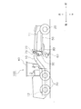
図1は、実施形態に係るモータグレーダ100の全体構成を示す側面図である。なお、以下の説明において、「上」「下」「左」「右」「前」「後」は、運転席に着座したオペレータを基準とする用語である。(Overall configuration of motor grader 100)
FIG. 1 is a side view showing an overall configuration of a
モータグレーダ100は、図1に示すように、フレーム10と、前輪20と、後輪30と、キャブ40と、ドローバ50と、ブレード60と、リフタガイド70と、リフタブラケット75と、一対のリフトシリンダ80と、シフトシリンダ90と、を備える。
As shown in FIG. 1, the
フレーム10は、前フレーム11と後フレーム12とによって構成される。前フレーム11は、ドローバ50およびブレード60を支持する。後フレーム12は、図示しないエンジンや油圧ポンプなどを支持する。前輪20は、フレーム10の前端部に取付けられる。後輪30は、フレーム10の後端部に取付けられる。本実施形態において、前輪20は左右1対の走行輪を含み、後輪30は左右2対の走行輪を含んでいるが、これに限られるものではない。キャブ40は、フレーム10上に配置される。
The
ドローバ50は、フレーム10の前端部に上下揺動可能に取付けられる。ブレード60は、ドローバ50の後端部に固定される。リフタガイド70は、フレーム10に接合(溶接)される環状部材である。リフタブラケット75は、リフタガイド70を取り囲む枠体である。リフタブラケット75には、一対のリフトシリンダ80とシフトシリンダ90とが取り付けられる。リフタガイド70周りの構成については後述する。なお、本実施形態において、ドローバ50とブレード60とは、フレーム10の下方に配置される作業機を構成している。
The
一対のリフトシリンダ80(図1では右リフトシリンダのみ図示)は、ドローバ50とリフタブラケット75とに連結される。一対のリフトシリンダ80の伸縮に応じてドローバ50およびブレード60が上下に揺動される。シフトシリンダ90は、ドローバ50とリフタブラケット75とに連結される。シフトシリンダ90の伸縮に応じてドローバ50およびブレード60が左右に駆動される。
A pair of lift cylinders 80 (only the right lift cylinder is shown in FIG. 1) is connected to the
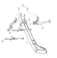
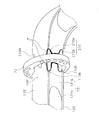
(リフタガイド70周りの構成)
図2は、リフタガイド70周りの構成を示す分解斜視図である。(Configuration around lifter guide 70)
FIG. 2 is an exploded perspective view showing a configuration around the
リフタガイド70は、フレーム10の所定の位置に接合される。図2では、フレーム10のうちリフタガイド70が接合される部分を接合部分10Pとして示している。フレーム10とリフタガイド70との接合構造については後述する。
The
リフタブラケット75は、上側枠体75aと、下側枠体75bと、を有する。上側枠体75aと下側枠体75bは、それぞれ半円環状に形成されており、リフタガイド70を挟み込むように互いに連結される。上側枠体75aには一対のリフトシリンダ80が取り付けられ、下側枠体75bにはシフトシリンダ90が取り付けられる。
The
(フレーム10とリフタガイド70との接合構造)
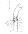
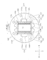
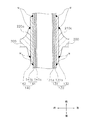
図3は、接合部分10Pの側面図である。図4は、図3のA−A断面図である。図5は、図3のB−B断面図である。図3および図5では、フレーム10とリフタガイド70とを接合する溶接部wが図示されている。溶接部wは、いわゆるビードである。(Junction structure of
FIG. 3 is a side view of the joint portion 10P. 4 is a cross-sectional view taken along line AA in FIG. 5 is a cross-sectional view taken along the line BB in FIG. 3 and 5, the welded portion w that joins the
(1)フレーム10の構成
フレーム10は、図3〜図5に示すように、上板110と、下板120と、第1側板130と、第2側板140と、によって構成されている。(1) Configuration of
上板110は、車幅方向(左右方向)に延びており、車幅方向と略平行に配置される。上板110は、車幅方向において幅W1を有する。
The
下板120は、車幅方向に延びており、上板110に対向する。下板120は、車幅方向において上板110と同じ幅W1を有する。
The
第1側板130は、上板110と下板120の間に挟まれている。第1側板130は、第1本体板131と、第1補強板132と、によって構成されている。第1本体板131は、上下方向に延びており、上下方向と略平行に配置される。第1本体板131は、上板110及び下板120の左端より車幅方向内側に配置されている。第1本体板131は、内板131aと、外板131bとを含む。外板131bは、内板131aの主面上に配置されており、フレーム10の湾曲部の強度を確保するための部材である。第1補強板132は、第1本体板131の主面上に配置されており、フレーム10とリフタガイド70との接合強度を向上させるための部材である。
The
第2側板140は、上板110と下板120の間に挟まれている。第2側板140は、第2本体板141と、第2補強板142と、によって構成されている。第2本体板141は、上下方向に延びており、第1本体板131に対向する。第2本体板141は、上板110及び下板120の右端より車幅方向内側に配置されている。第2本体板141は、内板141aと、外板141bとを含む。外板141bは、内板141aの主面上に配置されており、フレーム10の湾曲部の強度を確保するための部材である。第2補強板142は、第2本体板141の主面上に配置されており、フレーム10とリフタガイド70との接合強度を向上させるための部材である。
The
ここで、第1本体板131の左端と第2本体板141の右端との車幅方向における幅W2は、上板110および下板120の幅W1よりも狭い。
Here, the width W2 in the vehicle width direction between the left end of the first
一方で、第1側板130の左端と第2側板140の右端との車幅方向における幅W3は、上板110および下板120の幅W1と同等である。
On the other hand, the width W 3 in the vehicle width direction between the left end of the
そのため、上板110の左側面110Lと、第1側板130の左側面130Lと、下板120の左側面120Lと、が面一となって上下方向に延びる平面を形成している。また、上板110の右側面110Rと、第1側板130の右側面130Rと、下板120の右側面120Rと、が面一となって上下方向に延びる平面を形成している。
Therefore, the
(2)リフタガイド70の構成
リフタガイド70は、図3〜図5に示すように、環状部200と、左脚部210と、右脚部220と、によって構成されている。(2) Configuration of
環状部200は、フレーム10(接合部分10P)の外周を取り囲んでいる。環状部200は、リフタブラケット75の固定位置を変更するための複数の孔を有している。
The
左脚部210は、環状部の内周に連なっており、図4に示すように、左側面視において環状部200の前後に突出している。左脚部210は、第1上脚210aと第1下脚210bとを含んでいる。第1上脚210aおよび第1下脚210bは、環状部200の内側に配置され、フレーム10に沿って前後方向に延びるように形成されている。第1上脚210aおよび第1下脚210bの外縁は、フレーム10に溶接されている。より具体的には、第1上脚210aの外縁が、上板110の左側面110Lと、第1側板130の左側面130Lとに対して、溶接部wによって接合されている。同様に、第1下脚210bの外縁が、第1側板130の左側面130Lと、下板120の左側面120Lとに対して、溶接部wによって接合されている。このように、左脚部210の外縁は、第1側板130だけでなく上板110および下板120にも溶接されている。なお、第1上脚210aと第1下脚210bは、図4に示すように、上下方向において互いに離間している。
The
また、右脚部220は、環状部の内周に連なっており、図示しないが、右側面視において環状部200の前後に突出している。右脚部220は、左脚部210と同様に、第2上脚220aと第2下脚220bとを含んでいる。第2上脚220aおよび第2下脚220bは、環状部200の内側に配置され、フレーム10に沿って前後方向に延びるように形成されている。第1上脚210aおよび第1下脚210bの外縁は、フレーム10に溶接されている。より具体的には、第2上脚220aの外縁は、上板110の右側面110Rと、第2側板140の右側面140Rとに対して、溶接部wによって接合されている。同様に、第2下脚220bの外縁は、第2側板140の右側面140Rと、下板120の右側面120Rとに対して、溶接部wによって接合されている。このように、第2上脚220aおよび第2下脚220bは、第2側板140だけでなく上板110および下板120にも溶接されている。なお、第2上脚220aと第2下脚220bは、図4に示すように、上下方向において離間している。
Further, the
ここで、図3に示すように、左脚部210の第1上脚210aおよび第1下脚210bそれぞれの幅は、環状部200から離れるほど狭くなっている。すなわち、第1上脚210aおよび第1下脚210bそれぞれは、側面視において、環状部200から離れる方向に向かってテーパー状に形成されている。このことは、図示しないが、右脚部220の第2上脚220aおよび第2下脚220bにおいても同様である。
Here, as shown in FIG. 3, the width of each of the first
また、図5に示すように、左脚部210の第1上脚210aおよび右脚部220の第2上脚220aそれぞれの厚みは、環状部200から離れるほど薄くなっている。すなわち、第1上脚210aおよび第2上脚220aそれぞれは、断面において、環状部200から離れる方向に向かってテーパー状に形成されている。このことは、図示しないが、左脚部210の第1下脚210bおよび右脚部220の第2下脚220bにおいても同様である。
Further, as shown in FIG. 5, the thickness of each of the first
(作用および効果)
(1)実施形態に係るリフタガイド70は、フレーム10の外周を取り囲む環状部200と、環状部200の内周に連なるとともに側面視において環状部200から突出しており、外縁をフレーム10に接合される左脚部210(「第1脚部」の一例)とを有する。(Function and effect)
(1) The
このように、リフタガイド70が左脚部210と右脚部220を有しているので、フレーム10とリフタガイド70との接合範囲(すなわち、溶接部wの溶接線長さ)を長くすることができる。そのため、リフタガイド70とフレーム10との接合強度を向上させることができる。
As described above, since the
(2)フレーム10のうちリフタガイド70が接合される領域を接合部分10Pにおいて、上板110および下板120の幅W1と第1側板130と第2側板140との幅W3とが同等である。左脚部210の外縁は、上板110の左側面110Lと、第1側板130の左側面130Lと、下板120の左側面120Lと、に接合されている。
(2) The width W1 of the
このように、上板110および下板120の幅W1と第1側板130と第2側板140との幅W3とを同等にすることによって、左脚部210を上板110および下板120に接合することが実現されている。その結果、フレーム10とリフタガイド70との接合範囲をさらに大きくできるので、リフタガイド70とフレーム10との接合強度をさらに向上させることができる。
Thus, the
なお、このような効果は、右脚部220によっても同様に得ることができる。
Such an effect can be similarly obtained by the
(3)第1側板130は、第1本体板131と、第1補強板132と、によって構成されている。
(3) The
このように、第1補強板132を介挿することによって、上板110および下板120の幅W1と第1側板130と第2側板140との幅W3とが同等にされている。そのため、上述の通り接合範囲をさらに大きくできるだけでなく、フレーム10自体の強度を向上させることができる。
Thus, by inserting the first reinforcing
なお、このような効果は、第2側板140が第2本体板141と第2補強板142とで構成されていることによっても同様に得ることができる。
In addition, such an effect can be similarly obtained when the
(4)左脚部210は、側面視において環状部200の前後に突出している。
(4) The
従って、左脚部210によって環状部200を前後からバランス良く支持できるとともに、フレーム10とリフタガイド70との接合範囲をさらに大きくできる。そのため、リフタガイド70とフレーム10との接合強度をさらに向上させることができる。
Therefore, the
(5)左脚部210は、互いに離間する第1上脚210aと第1下脚210bとを含む。
(5) The
従って、上下に揺動するフレーム10に対してリフタガイド70を第1上脚210aと第1下脚210bとによって強固に支持できる。また、第1上脚210aと第1下脚210bとが離間しているので、第1上脚210aと第1下脚210bとが一様に連なっている場合に比べて、フレーム10とリフタガイド70との接合部分に不均等に応力がかかることを抑制できるので、リフタガイド70とフレーム10との接合力が低下することを抑制できる。
Therefore, the
なお、このような効果は、右脚部220が互いに離間する第2上脚220aと第2下脚220bとを含むことによっても同様に得ることができる。
Such an effect can be similarly obtained by including the second
(6)第1上脚210aおよび第1下脚210bそれぞれの幅は、環状部200から離れるほど狭い。このように各脚の幅を徐々に狭くすることによって、第1上脚210aおよび第1下脚210bの特定の箇所に大きな応力が集中することを抑制することができる。
(6) The width of each of the first
(7)第1上脚210aおよび第2上脚220aそれぞれの厚みは、環状部200から離れるほど薄い。このように各脚の厚みを徐々に薄くすることによって、第1上脚210aおよび第1下脚210bの特定の箇所に大きな応力が集中することを抑制することができる。
(7) The thicknesses of the first
(その他の実施形態)
以上、本発明の一実施形態について説明したが、本発明は上記実施形態に限定されるものではなく、発明の要旨を逸脱しない範囲で種々の変更が可能である。(Other embodiments)
As mentioned above, although one Embodiment of this invention was described, this invention is not limited to the said embodiment, A various change is possible in the range which does not deviate from the summary of invention.
(A)上記実施形態では、第1側板130の第1補強板132と第2側板140の第2補強板142とを介挿することによって、上板110および下板120の幅W1と第1側板130と第2側板140との幅W3とを同等にすることとしたが、これに限られるものではない。
(A) In the above embodiment, by inserting the first reinforcing
図6に示すように、第1側板130が第1本体板131のみによって構成される場合には、上板110に上側切欠き部110Mを形成するとともに、下板120に下側切欠き部110Nを形成すればよい。これによって、上板110および下板120の幅W1と第1側板130と第2側板140との幅W3とを同等にすることができ、その結果、上板110の左側面110Lと、第1側板130の左側面130Lと、下板120の左側面120Lとを面一にすることができる。さらに、この場合には、接合範囲をさらに大きくできるだけでなく、フレーム10自体の重量を軽減することもできる。このことは、第2側板140側においても同様である。
As shown in FIG. 6, when the
なお、図6では、フレーム10とリフタガイド70とを接合する溶接部wが図示されている。
In FIG. 6, a welded portion w that joins the
(B)上記実施形態では、左脚部210は、互いに離間する第1上脚210aと第1下脚210bとを含むこととしたが、これに限られるものではない。左脚部210は、1つの脚によって構成されていてもよいし、3以上の脚によって構成されていてもよい。このことは、右脚部220においても同様である。
(B) In the above-described embodiment, the
(C)上記実施形態では、左脚部210は、側面視において環状部200の前後に突出することとしたが、これに限られるものではない。左脚部210は、側面視において環状部200の前方又は後方のいずれか一方のみに突出していてもよい。このことは、右脚部220においても同様である。
(C) In the above embodiment, the
(D)上記実施形態では、リフタガイド70は、左脚部210と右脚部220とを有することとしたが、これに限られるものではない。リフタガイド70は、左脚部210と右脚部220のいずれか一方のみを有していてもよい。
(D) In the above embodiment, the
本発明に係るモータグレーダは、リフタガイドとフレームとの接合強度を向上できるため、建設機械分野において有用である。 The motor grader according to the present invention can improve the bonding strength between the lifter guide and the frame, and is useful in the construction machine field.
10 フレーム
10P 接合部分
20 前輪
30 後輪
40 キャブ
50 ドローバ
60 ブレード
70 リフタガイド
75 リフタブラケット
75a 上側枠体
75b 下側枠体
80 リフトシリンダ
90 シフトシリンダ
100 モータグレーダ
110 上板
110M 上側切欠き部
110N 下側切欠き部
120 下板
130 第1側板
131 第1本体板
131a 内板
131b 外板
132 第1補強板
140 第2側板
141 第2本体板
141a 内板
141b 外板
142 第2補強板
200 環状部
210 左脚部
210a 第1上脚
210b 第1下脚
220 右脚部
220a 第2上脚
220b 第2下脚
w 溶接部10
Claims (12)
前記フレームの下方に配置される作業機と、
前記フレームを取り囲み、前記フレームに接合されるリフタガイドと、
前記リフタガイドを取り囲むリフタブラケットと、
前記リフタブラケットに取り付けられ、前記作業機を駆動するためのリフトシリンダと、
を備え、
前記リフタガイドは、
前記フレームの外周を取り囲む環状部と、
前記環状部の内周に連なるとともに側面視において前記環状部から突出しており、外縁を前記フレームに溶接される第1脚部と、
を有し、
前記フレームは、車幅方向に延びる上板と、前記上板に対向する下板と、上下方向に延び、前記上板と前記下板に挟まれる第1側板と、前記第1側板に対向し、前記上板と前記下板に挟まれる第2側板と、によって構成されており、
前記フレームのうち前記リフタガイドが接合される接合部分において、前記上板および前記下板それぞれの前記車幅方向両端の幅は、前記第1側板および前記第2側板の前記車幅方向両端の幅と同等であり、
前記第1脚部の前記外縁は、前記上板の側面と、前記第1側板の側面と、前記下板の側面とに接合されている、
モータグレーダ。 Frame,
A working machine disposed below the frame;
A lifter guide that surrounds the frame and is joined to the frame;
A lifter bracket surrounding the lifter guide;
A lift cylinder attached to the lifter bracket for driving the work implement;
With
The lifter guide is
An annular portion surrounding the outer periphery of the frame;
A first leg that is continuous with the inner periphery of the annular part and protrudes from the annular part in a side view, and whose outer edge is welded to the frame;
I have a,
The frame includes an upper plate extending in the vehicle width direction, a lower plate facing the upper plate, a first side plate extending in the vertical direction and sandwiched between the upper plate and the lower plate, and facing the first side plate. The second side plate sandwiched between the upper plate and the lower plate,
In the joint portion of the frame where the lifter guide is joined, the widths of the upper plate and the lower plate at both ends in the vehicle width direction are the widths of the first side plate and the second side plate at both ends in the vehicle width direction. Is equivalent to
The outer edge of the first leg is joined to the side surface of the upper plate, the side surface of the first side plate, and the side surface of the lower plate.
Motor grader.
請求項1に記載のモータグレーダ。 The first side plate is constituted by a main body plate arranged inside one end in the vehicle width direction of each of the upper plate and the lower plate, and a reinforcing plate arranged outside the main body plate,
The motor grader according to claim 1 .
前記上板は、前記接合部分に形成される上側切欠き部を有し、
前記下板は、前記上側切欠き部に対応して形成される下側切欠き部を有している、
請求項1に記載のモータグレーダ。 The first side plate is constituted by a main body plate disposed inside one end in the vehicle width direction of each of the upper plate and the lower plate,
The upper plate has an upper notch formed in the joining portion,
The lower plate has a lower notch formed to correspond to the upper notch.
The motor grader according to claim 1 .
請求項1乃至3のいずれかに記載のモータグレーダ。 The first leg protrudes forward and backward of the annular portion in a side view,
The motor grader according to any one of claims 1 to 3 .
前記第1上脚と前記第1下脚とは、互いに離間している、
請求項1乃至4のいずれかに記載のモータグレーダ。 The first leg portion is joined to the side surface of the upper plate and the side surface of the first side plate, and to the side surface of the first side plate and the side surface of the lower plate. Including 1 lower leg,
The first upper leg and the first lower leg are spaced apart from each other;
Motor grader according to any one of claims 1 to 4.
請求項5に記載のモータグレーダ。 The width of each of the first upper leg and the first lower leg is so narrow that it is away from the annular portion,
The motor grader according to claim 5 .
請求項5又は6に記載のモータグレーダ。 The thickness of each of the first upper leg and the first lower leg is so thin that it is away from the annular portion,
The motor grader according to claim 5 or 6 .
前記第2脚部は、前記フレームを挟んで前記第1脚部の反対側に設けられる、
請求項1乃至7のいずれかに記載のモータグレーダ。 The lifter guide includes a second leg portion that is continuous with the inner periphery of the annular portion and protrudes from the annular portion in a side view, and has an outer edge welded to the frame.
The second leg is provided on the opposite side of the first leg across the frame,
Motor grader according to any one of claims 1 to 7.
請求項8に記載のモータグレーダ。 The second leg protrudes forward and backward of the annular portion in a side view,
The motor grader according to claim 8 .
前記第2上脚と前記第2下脚とは、互いに離間している、
請求項8又は9に記載のモータグレーダ。 The second leg portion is joined to the side surface of the upper plate and the side surface of the second side plate, and the second leg portion is joined to the side surface of the second side plate and the side surface of the lower plate. 2 lower legs,
The second upper leg and the second lower leg are separated from each other,
The motor grader according to claim 8 or 9 .
請求項10に記載のモータグレーダ。 The widths of the second upper leg and the second lower leg are so narrow that they are separated from the annular portion,
The motor grader according to claim 10 .
請求項10又は11に記載のモータグレーダ。 The thicknesses of the second upper leg and the second lower leg are so thin that they are separated from the annular portion,
The motor grader according to claim 10 or 11 .
Priority Applications (1)
| Application Number | Priority Date | Filing Date | Title |
|---|---|---|---|
| JP2012527557A JP5259019B2 (en) | 2011-06-01 | 2012-03-28 | Motor grader |
Applications Claiming Priority (4)
| Application Number | Priority Date | Filing Date | Title |
|---|---|---|---|
| JP2011123780 | 2011-06-01 | ||
| JP2011123780 | 2011-06-01 | ||
| PCT/JP2012/058097 WO2012165014A1 (en) | 2011-06-01 | 2012-03-28 | Motor grader |
| JP2012527557A JP5259019B2 (en) | 2011-06-01 | 2012-03-28 | Motor grader |
Publications (2)
| Publication Number | Publication Date |
|---|---|
| JP5259019B2 true JP5259019B2 (en) | 2013-08-07 |
| JPWO2012165014A1 JPWO2012165014A1 (en) | 2015-02-23 |
Family
ID=47258880
Family Applications (1)
| Application Number | Title | Priority Date | Filing Date |
|---|---|---|---|
| JP2012527557A Expired - Fee Related JP5259019B2 (en) | 2011-06-01 | 2012-03-28 | Motor grader |
Country Status (5)
| Country | Link |
|---|---|
| US (1) | US9080318B2 (en) |
| JP (1) | JP5259019B2 (en) |
| CN (1) | CN103080428B (en) |
| DE (1) | DE112012000084T5 (en) |
| WO (1) | WO2012165014A1 (en) |
Families Citing this family (5)
| Publication number | Priority date | Publication date | Assignee | Title |
|---|---|---|---|---|
| US9255379B2 (en) | 2013-06-18 | 2016-02-09 | Komatsu Ltd. | Motor grader |
| CN106592666A (en) * | 2016-12-22 | 2017-04-26 | 广西柳工机械股份有限公司 | Working device adjustment mechanism of land leveller, and land leveller |
| JP7138098B2 (en) * | 2018-04-25 | 2022-09-15 | 株式会社小松製作所 | Work machine of motor grader |
| WO2021084673A1 (en) * | 2019-10-31 | 2021-05-06 | 株式会社小松製作所 | Frame of work vehicle and work vehicle |
| US20220195692A1 (en) * | 2020-12-23 | 2022-06-23 | Deere & Company | Work machine with a saddle frame assembly |
Citations (5)
| Publication number | Priority date | Publication date | Assignee | Title |
|---|---|---|---|---|
| JPS5080203U (en) * | 1973-11-21 | 1975-07-10 | ||
| JPS5080207U (en) * | 1973-11-22 | 1975-07-10 | ||
| JPS5316301U (en) * | 1976-07-23 | 1978-02-10 | ||
| JPS5416121B1 (en) * | 1966-06-21 | 1979-06-20 | ||
| WO2007015376A1 (en) * | 2005-08-03 | 2007-02-08 | Komatsu Ltd. | Motor grader |
Family Cites Families (9)
| Publication number | Priority date | Publication date | Assignee | Title |
|---|---|---|---|---|
| US1547263A (en) * | 1921-02-10 | 1925-07-28 | Pomeroy Laurence Henry | Motor-vehicle frame |
| US2247982A (en) * | 1939-12-20 | 1941-07-01 | Galion Iron Works & Mfg Co | Road grader |
| US2655743A (en) * | 1950-11-16 | 1953-10-20 | W A Riddell Corp | Road working apparatus |
| US3327413A (en) * | 1964-06-22 | 1967-06-27 | Deere & Co | Material grading implement |
| US4807461A (en) * | 1986-01-21 | 1989-02-28 | Deere & Company | Motor grader main frame |
| US5741026A (en) * | 1996-05-31 | 1998-04-21 | Dana Corporation | Connecting and supporting structure for vehicle frame assembly |
| JP3514694B2 (en) | 2000-03-17 | 2004-03-31 | 株式会社クボタ | Undercarriage structure of turning machine |
| JP2010053641A (en) | 2008-08-29 | 2010-03-11 | Caterpillar Japan Ltd | Blade apparatus |
| US9096994B2 (en) * | 2012-02-15 | 2015-08-04 | Deere & Company | Bottom mount blade positioning assembly for a motor grader |
-
2012
- 2012-03-28 WO PCT/JP2012/058097 patent/WO2012165014A1/en not_active Ceased
- 2012-03-28 DE DE112012000084T patent/DE112012000084T5/en not_active Withdrawn
- 2012-03-28 JP JP2012527557A patent/JP5259019B2/en not_active Expired - Fee Related
- 2012-03-28 US US13/822,693 patent/US9080318B2/en not_active Expired - Fee Related
- 2012-03-28 CN CN201280002503.1A patent/CN103080428B/en not_active Expired - Fee Related
Patent Citations (5)
| Publication number | Priority date | Publication date | Assignee | Title |
|---|---|---|---|---|
| JPS5416121B1 (en) * | 1966-06-21 | 1979-06-20 | ||
| JPS5080203U (en) * | 1973-11-21 | 1975-07-10 | ||
| JPS5080207U (en) * | 1973-11-22 | 1975-07-10 | ||
| JPS5316301U (en) * | 1976-07-23 | 1978-02-10 | ||
| WO2007015376A1 (en) * | 2005-08-03 | 2007-02-08 | Komatsu Ltd. | Motor grader |
Also Published As
| Publication number | Publication date |
|---|---|
| CN103080428B (en) | 2015-04-01 |
| US20130175064A1 (en) | 2013-07-11 |
| US9080318B2 (en) | 2015-07-14 |
| CN103080428A (en) | 2013-05-01 |
| WO2012165014A1 (en) | 2012-12-06 |
| DE112012000084T5 (en) | 2013-08-08 |
| JPWO2012165014A1 (en) | 2015-02-23 |
Similar Documents
| Publication | Publication Date | Title |
|---|---|---|
| JP5259019B2 (en) | Motor grader | |
| US8079636B2 (en) | Cab for construction machine | |
| JP6372057B2 (en) | Trailing arm mounting structure | |
| JP6159974B2 (en) | Front cross member | |
| KR100979429B1 (en) | Upper frame of construction machinery | |
| US7997619B2 (en) | Track frame for work machine | |
| US10024026B2 (en) | Front loader frame, front loader equipped with front loader frame, and work vehicle equipped with front loader | |
| WO2013027602A1 (en) | Kick-up frame connection structure | |
| JP5674577B2 (en) | boom | |
| JP5077330B2 (en) | Construction machine upper frame | |
| JP4984923B2 (en) | Construction machine upper frame | |
| JP5903456B2 (en) | Manufacturing method of body frame of saddle riding type vehicle | |
| CN106476879B (en) | Turn to supporting beam structure | |
| JP4978640B2 (en) | Work machine frame | |
| JP7370967B2 (en) | Work vehicle frame and work vehicle | |
| WO2014185553A1 (en) | Utility vehicle | |
| JP2015193331A (en) | Structure of trailing arm attachment part | |
| WO2014203323A1 (en) | Motor grader | |
| CN220948263U (en) | Track frame and reinforcing bending plate thereof | |
| JP5760854B2 (en) | Work machine | |
| JP6990353B2 (en) | Rear reinforcement structure of the car body | |
| JP2010095133A (en) | Upper frame of construction machine and its assembling method | |
| JP6090353B2 (en) | Boom foot part of work machine | |
| JP6455130B2 (en) | Crane vehicle outrigger reinforcement structure | |
| JP4403057B2 (en) | Body frame of refraction steering work vehicle |
Legal Events
| Date | Code | Title | Description |
|---|---|---|---|
| TRDD | Decision of grant or rejection written | ||
| A01 | Written decision to grant a patent or to grant a registration (utility model) |
Free format text: JAPANESE INTERMEDIATE CODE: A01 Effective date: 20130409 |
|
| A61 | First payment of annual fees (during grant procedure) |
Free format text: JAPANESE INTERMEDIATE CODE: A61 Effective date: 20130423 |
|
| FPAY | Renewal fee payment (event date is renewal date of database) |
Free format text: PAYMENT UNTIL: 20160502 Year of fee payment: 3 |
|
| R150 | Certificate of patent or registration of utility model |
Free format text: JAPANESE INTERMEDIATE CODE: R150 Ref document number: 5259019 Country of ref document: JP Free format text: JAPANESE INTERMEDIATE CODE: R150 |
|
| LAPS | Cancellation because of no payment of annual fees |