JP5258372B2 - Imaging apparatus and control method thereof - Google Patents
Imaging apparatus and control method thereof Download PDFInfo
- Publication number
- JP5258372B2 JP5258372B2 JP2008122775A JP2008122775A JP5258372B2 JP 5258372 B2 JP5258372 B2 JP 5258372B2 JP 2008122775 A JP2008122775 A JP 2008122775A JP 2008122775 A JP2008122775 A JP 2008122775A JP 5258372 B2 JP5258372 B2 JP 5258372B2
- Authority
- JP
- Japan
- Prior art keywords
- transfer unit
- noise
- transfer
- unit
- driving
- Prior art date
- Legal status (The legal status is an assumption and is not a legal conclusion. Google has not performed a legal analysis and makes no representation as to the accuracy of the status listed.)
- Expired - Fee Related
Links
Images


Classifications
-
- H—ELECTRICITY
- H04—ELECTRIC COMMUNICATION TECHNIQUE
- H04N—PICTORIAL COMMUNICATION, e.g. TELEVISION
- H04N25/00—Circuitry of solid-state image sensors [SSIS]; Control thereof
- H04N25/70—SSIS architectures; Circuits associated therewith
- H04N25/71—Charge-coupled device [CCD] sensors; Charge-transfer registers specially adapted for CCD sensors
Description
本発明は、撮像装置及びその制御方法と、画像処理装置及び補正方法に関し、更に詳しくは、撮像素子の駆動に起因して発生するノイズを軽減する撮像装置及びその制御方法と、画像処理装置及び補正方法に関する。 The present invention relates to an imaging apparatus, a control method thereof, an image processing apparatus, and a correction method, and more particularly, an imaging apparatus that reduces noise generated due to driving of an imaging element, a control method thereof, an image processing apparatus, and It relates to a correction method.
近年、固体メモリ素子を有するメモリカードを記録媒体として、CCD等の固体撮像素子で撮像した画像を記録及び再生するデジタルカメラ等の撮像装置が盛んに開発され、広く普及してきている。このような普及の背景としては、デジタルカメラで撮影した画像を取り込んで処理できるパーソナルコンピュータ(PC)の普及と、インターネットなどを利用したデジタル画像情報の需要が高まったことなどがあげられる。 2. Description of the Related Art In recent years, imaging devices such as digital cameras that record and reproduce images captured by a solid-state imaging device such as a CCD using a memory card having a solid-state memory element as a recording medium have been actively developed and widely spread. The background of such spread is the spread of personal computers (PCs) that can capture and process images taken with digital cameras, and the demand for digital image information using the Internet and the like has increased.
そして、静止画の記憶を機能の中心とするデジタルスチルカメラと、動画の記憶を機能の中心とするデジタルビデオカメラとが、それぞれ、静止画及び動画の双方を記憶する機能を有するようになってきている。そして、静止画や動画の撮影に係る解像度や動作スピードの向上に対する市場ニーズは、年々増加している。 Digital still cameras whose function is still image storage and digital video cameras whose function is mainly moving image memory have a function of storing both still images and moving images. ing. And market needs for improvement in resolution and operation speed related to still image and video shooting are increasing year by year.
さらに、最近では、解像度や動作スピードの向上に加えて、様々な撮影シーンにおいて、失敗の少ない撮影を手軽に行えることがより一層求められるようになってきた。そのため、たとえばスポーツシーンなど動きの速い被写体に追従するため、あるいは、低照明下の室内撮影における手ぶれ防止を目的とした、シャッター秒時の高速化が進んでいる。また、美術館、水族館といったフラッシュ撮影が禁止されたエリアでの高感度撮影を可能とするために、静止画や動画の撮影に係る高感度化も、さらに度合いを強めている。 Furthermore, in recent years, in addition to improvements in resolution and operation speed, there has been a further demand for easy shooting with few failures in various shooting scenes. For this reason, for example, in order to follow a fast-moving subject such as a sports scene or to prevent camera shake in indoor shooting under low illumination, the shutter speed has been increased. In addition, in order to enable high-sensitivity shooting in areas where flash shooting is prohibited, such as museums and aquariums, the degree of sensitivity for shooting still images and moving images is also increasing.
一方、CCD等の固体撮像素子を用いた撮像装置において、静止画撮影の連写スピードや動画撮影のフレームレートを上げるために、水平転送レジスタから有効領域の画素の電荷を転送中に並行して垂直転送レジスタの転送を行う読み出し駆動方法がある。しかし、この駆動方法では、垂直転送時の駆動パルス(垂直転送パルス)の立ち上がり及び立下りのタイミングで、水平転送レジスタから読み出された有効領域の画素の信号(以下、「有効画素信号」と呼ぶ。)にクロストークノイズが重畳するという問題がある。 On the other hand, in an image pickup apparatus using a solid-state image pickup device such as a CCD, in order to increase the continuous shooting speed for still image shooting and the frame rate for moving image shooting, the charges of the pixels in the effective area are transferred in parallel from the horizontal transfer register. There is a read driving method for transferring a vertical transfer register. However, in this driving method, the pixel signal in the effective area (hereinafter referred to as “effective pixel signal”) read from the horizontal transfer register at the rising and falling timings of the driving pulse (vertical transfer pulse) during vertical transfer. There is a problem that the crosstalk noise is superimposed on.
上記垂直転送パルスによるクロストークノイズは、撮像素子内部の基板や信号電極間などの様々な伝達経路を通じて有効画素信号に漏れ込むため、ノイズの重畳を防止することが難しい。さらに、上記垂直転送パルスによるクロストークノイズは、水平ライン毎に同じ列位置の有効画素信号に重畳する縦線状のノイズとなるため、視覚上も画像ノイズとして目立ち易いという欠点がある。 The crosstalk noise due to the vertical transfer pulse leaks into the effective pixel signal through various transmission paths such as the substrate inside the image sensor and between the signal electrodes, so it is difficult to prevent noise from being superimposed. Further, the crosstalk noise due to the vertical transfer pulse is a vertical line noise superimposed on the effective pixel signal at the same column position for each horizontal line, and thus has a drawback that it is easily noticeable as image noise visually.
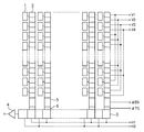
ここで、上記従来の撮像素子の構成の一例について説明する。図8は撮像素子(CCD)の概略構成を示す図である。 Here, an example of the configuration of the conventional imaging device will be described. FIG. 8 is a diagram showing a schematic configuration of an image sensor (CCD).
同図において、1は光電変換素子であるPD(フォトダイオード)であり、行方向及び列方向に2次元配列されている。2はPD1の信号電荷を垂直方向(列方向)に転送するための複数の垂直転送レジスタである垂直CCD(VCCD、第1の転送部)で、通常、4相駆動構成となっている。 In the figure, reference numeral 1 denotes a PD (photodiode) which is a photoelectric conversion element, which is two-dimensionally arranged in a row direction and a column direction. Reference numeral 2 denotes a vertical CCD (VCCD, first transfer unit) which is a plurality of vertical transfer registers for transferring the signal charge of the PD 1 in the vertical direction (column direction), and normally has a four-phase drive configuration.
3はVCCD2から転送されてきた1ライン毎の信号電荷を転送する水平CCD(HCCD、第2の転送部)で2相駆動構成となっている。4はHCCD3から転送されてきた1画素毎の信号電荷を電圧信号に変換して出力するための出力アンプである。
5は、VCCD2により転送されてきた1ライン分の信号電荷をHCCD3へ転送するまでに一旦蓄積しておくバッファストレージセル(BS)、6はBS5とHCCD3の間のトランスファーゲート(TG)である。
Reference numeral 5 denotes a buffer storage cell (BS) for temporarily storing the signal charge for one line transferred by the VCCD 2 until it is transferred to the
図8においてVCCD2の4つの転送電極には垂直転送パルスV1、V2、V3、V4がそれぞれ印加されており、HCCD3の2つの転送電極には、水平転送パルスH1、H2がそれぞれ印加されている。 In FIG. 8, vertical transfer pulses V1, V2, V3, V4 are respectively applied to the four transfer electrodes of VCCD2, and horizontal transfer pulses H1, H2 are respectively applied to the two transfer electrodes of HCCD3.
図9は図8に示す構成を有する撮像素子の従来の撮像駆動方法を説明するためのタイミング図であり、VCCD2及びHCCD3によって、出力アンプ4にCCDの信号電荷が出力されるタイミングを示している。
Figure 9 is a timing diagram for explaining the conventional imaging method of driving the imaging device having the structure shown in FIG. 8, by VCCD2 and
そして、図9のタイミング図に示すように、VCCD2における信号電荷の転送動作を、水平有効動作期間、すなわち、HCCD3における転送動作と時間的に並行して行うことにより水平ブランキング期間(HBLK)の短縮を行っている。
Then, as shown in the timing chart of FIG. 9, the signal charge transfer operation in the VCCD 2 is performed in parallel with the horizontal effective operation period, that is, the transfer operation in the
しかしながら、水平有効動作期間中にVCCD2における転送動作を行うために、VCCD2に印加された垂直転送パルスV1、V2、V3、V4のそれぞれの立ち上がり、立下りのタイミングでCCD内部でクロストークノイズが発生する。そのため、最終的に出力アンプ4から読み出される撮像電圧信号(CCD出力)にはクロストークノイズが重畳する結果となる。
However, in order to perform the transfer operation in the VCCD 2 during the horizontal effective operation period, crosstalk noise is generated inside the CCD at the rising and falling timings of the vertical transfer pulses V1, V2, V3, and V4 applied to the VCCD 2. To do. Therefore, the crosstalk noise is superimposed on the imaging voltage signal (CCD output) that is finally read from the
垂直転送パルスによるクロストークノイズは、図9の下向きの矢印で示すように、水平ライン毎に常に同じ水平位置の画素に対して、ほぼ同一レベルのノイズとして重畳する。そのため、水平ラインを並べた2次元画像上では縦線ノイズとなって現れる。また、読み出された撮像電圧信号は、出力アンプ4の後段に位置する不図示の感度切り換え用のゲインアンプによって増幅される。そのため、撮像装置における感度設定が高い場合、すなわちゲインアンプの増幅度が大きい場合ほど、クロストークノイズは顕在化して目立ち易くなる。
As shown by the downward arrow in FIG. 9, the crosstalk noise due to the vertical transfer pulse is always superimposed as substantially the same level of noise on the pixels at the same horizontal position for each horizontal line. Therefore, it appears as vertical line noise on a two-dimensional image in which horizontal lines are arranged. The read imaging voltage signal is amplified by a sensitivity switching gain amplifier (not shown) located at the subsequent stage of the
上記問題に対処するために、撮像素子から部分読み出しを行う時に限って、不要電荷読み出し期間に上記駆動方法を用いることで、読み出し時間の短縮とフレームレートの向上を実現するための技術が開示されている(特許文献1参照)。 In order to cope with the above problem, a technique for reducing the readout time and improving the frame rate by using the above driving method in the unnecessary charge readout period only when partial readout from the image sensor is disclosed. (See Patent Document 1).
また、垂直転送パルスの立ち上がり及び立下りの傾きを小さくしたり、タイミングを工夫することで、有効画素信号に重畳するクロストークノイズの影響を軽減するための技術が開示されている(特許文献2参照)。 Further, a technique for reducing the influence of crosstalk noise superimposed on an effective pixel signal by reducing the rising and falling slopes of the vertical transfer pulse or devising the timing is disclosed (Patent Document 2). reference).
しかしながら、特許文献1に記載された技術では、測光動作や電子ズーム動作などの有効画素領域中の一部分の読み出しを行う場合には有効であるものの、通常の静止画や動画読み出し動作時に高速化することはできない。 However, the technique described in Patent Document 1 is effective when reading out a part of an effective pixel area such as a photometric operation or an electronic zoom operation, but speeds up during a normal still image or moving image read operation. It is not possible.
また、特許文献2に記載された技術では、有効画素信号に重畳するクロストークノイズの影響をあまり除去しきれできず、ノイズ成分が残留してしまう。撮像装置の感度条件の設定が高く、撮像回路の撮像信号に対する増幅度が大きい場合には、たとえ微弱なノイズ成分であっても画像ノイズとして顕在化してしまう。このことは撮像装置の高感度化を妨げる要因となる。 Further, with the technique described in Patent Document 2, the influence of crosstalk noise superimposed on the effective pixel signal cannot be removed so much that a noise component remains. When the sensitivity condition setting of the image pickup apparatus is high and the amplification degree with respect to the image pickup signal of the image pickup circuit is large, even a weak noise component becomes manifest as image noise. This is a factor that hinders high sensitivity of the imaging apparatus.
本発明は上記問題点を鑑みてなされたものであり、撮影時のフレームレートを落とすことなく、撮影して得られた画像信号におけるクロストークノイズの影響を低減することを目的とする。 The present invention has been made in view of the above problems, and an object of the present invention is to reduce the influence of crosstalk noise in an image signal obtained by photographing without reducing the frame rate at the time of photographing.
上記目的を達成するために、本発明の撮像装置は、行方向及び列方向に2次元配列された光電変換素子と、前記光電変換素子で発生した電荷信号を列方向に転送する第1の転送部と、前記第1の転送部により転送された電荷信号を行方向に転送する第2の転送部と、前記第2の転送部による電荷信号の転送中に、前記第1の転送部を駆動する駆動手段と、前記第2の転送部から出力された電荷信号について、前記第1の転送部の駆動に起因して発生するノイズを含むノイズを補正するノイズ補正手段と、感度、シャッター秒時、及び温度の少なくとも1つに基づいて、前記ノイズ補正手段によるノイズの補正を行うか否かを制御する制御手段とを有し、前記制御手段は、前記ノイズ補正手段によるノイズの補正を行わない場合に、前記第2の転送部が、1回の転送で前記第1の転送部から前記第2の転送部に転送された電荷信号を出力する毎に、前記第1の転送部を駆動するためのパルスを出力するタイミングをシフトするように前記駆動手段を制御する。 In order to achieve the above object, an imaging apparatus of the present invention includes a photoelectric conversion element that is two-dimensionally arranged in a row direction and a column direction, and a first transfer that transfers a charge signal generated in the photoelectric conversion element in the column direction. A second transfer unit for transferring the charge signal transferred by the first transfer unit in the row direction, and driving the first transfer unit during transfer of the charge signal by the second transfer unit Driving means , noise correcting means for correcting noise including noise generated due to driving of the first transfer unit, and sensitivity, shutter speed, for the charge signal output from the second transfer unit and based on at least one temperature, and a control means for controlling whether or not to correct the noise due to the noise correcting means, said control means does not perform the correction of the noise by the noise correction unit If the second Timing transmission unit, each for outputting a charge signal transferred to the second transfer unit from said first transfer unit in a single transfer, for outputting a pulse for driving the first transfer portion The driving means is controlled so as to shift.
また、行方向及び列方向に2次元配列された光電変換素子と、前記光電変換素子で発生した電荷信号を列方向に転送する第1の転送部と、前記第1の転送部により転送された電荷信号を行方向に転送する第2の転送部と、前記第2の転送部による電荷信号の転送中に、前記第1の転送部を駆動する駆動手段とを有する撮像装置の本発明の制御方法は、制御手段が、前記撮像装置の感度、シャッター秒時、及び温度の少なくとも1つに基づいて、前記第1の転送部の駆動に起因して発生するノイズを含むノイズの補正を行うか否かを判断する判断工程と、ノイズ補正手段が、前記ノイズの補正を行うと判断された場合に、前記第2の転送部から出力された電荷信号についてノイズを補正するノイズ補正工程と、前記制御手段が、前記ノイズの補正を行わないと判断された場合に、前記第2の転送部が、1回の転送で前記第1の転送部から前記第2の転送部に転送された電荷信号を出力する毎に、前記第1の転送部を駆動するためのパルスを出力するタイミングをシフトするように前記駆動手段を制御する制御工程とを有する。 In addition, the photoelectric conversion elements that are two-dimensionally arranged in the row direction and the column direction, the first transfer unit that transfers the charge signal generated in the photoelectric conversion elements in the column direction, and the first transfer unit Control of an imaging apparatus according to the present invention, comprising: a second transfer unit that transfers a charge signal in a row direction; and a driving unit that drives the first transfer unit during transfer of the charge signal by the second transfer unit. Whether the control means corrects noise including noise generated due to driving of the first transfer unit based on at least one of sensitivity, shutter speed, and temperature of the imaging device. A determination step of determining whether or not, a noise correction step of correcting noise for the charge signal output from the second transfer unit when the noise correction unit determines to correct the noise, and control means, complement of the noise If it is determined not to perform, for each of said second transfer unit, and outputs the charges signal transferred to the second transfer unit from said first transfer unit in a single transfer, the first and a controlling process of controlling the drive means so as to shift the timing of outputting a pulse for driving the first transfer portion.
本発明によれば、撮影時のフレームレートを落とすことなく、撮影して得られた画像信号におけるクロストークノイズの影響を低減することができる。 According to the present invention, it is possible to reduce the influence of crosstalk noise in an image signal obtained by photographing without reducing the frame rate at the time of photographing.
以下、添付図面を参照して本発明を実施するための最良の形態を詳細に説明する。 The best mode for carrying out the present invention will be described below in detail with reference to the accompanying drawings.
<第1の実施形態>
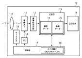
図1は、本発明の第1の実施形態に係る撮像装置10の概略構成を示すブロック図である。
<First Embodiment>
FIG. 1 is a block diagram showing a schematic configuration of an
図1において、12は入射した光を電気信号に変換する光電変換素子を有する、CCDなどにより構成された撮像素子であり、図8で示すものと基本的に同様な構成を有する。つまり、PD1の信号電荷を垂直方向(列方向)に転送するための複数の垂直転送レジスタである垂直CCD2と、VCCDから転送されてきた1ライン毎の信号電荷を水平方向(行方向)に転送する水平CCD3を有している。撮像素子12は、光電変換素子に接続されない状態で信号が読み出されるダミー画素部と、光学的に遮光された画素部であるOB部と、光学的に遮光されておらず、被写体からの光を受けて画像データを生成する画素部である有効画素部とを有する。11は被写体からの光を撮像素子12に集光するレンズである。
In FIG. 1,
13は、撮像素子12から出力されるアナログ画像信号をデジタル画像信号へ変換するA/D変換器を含む画像処理回路、14は撮像素子12を駆動するパルスを発生するタイミングジェネレータ(TG)である。
An
15はRAMにより構成された記憶部であり、撮影データを記憶する記憶領域19と画像データを記憶する記憶領域20とを含む。16は撮像装置10に着脱可能な記録媒体(ここではコンパクトフラッシュ(登録商標)カードもしくはSDカード)で、記憶領域20に一時的に記憶された画像データが最終的に記録される。
また、17は撮像装置10全体を制御する制御部(CPU)であり、制御部17の不図示の内部メモリには、後述するように縦線ノイズの補正を行うかどうかを判断するための条件を予め記述したノイズ補正ON/OFFテーブル171を記憶している。18は撮像素子12の周辺温度を測定するサーミスタである。
次に、図2のフローチャートを参照して、本発明の第1の実施形態における撮影処理の流れについて説明する。なお、ここでは、静止画撮影の場合について説明するが、動画撮影やライブビューモードにおいても、同様の処理により同様の効果をあげることができる。 Next, with reference to the flowchart of FIG. 2, the flow of the imaging process in the first embodiment of the present invention will be described. Although the case of still image shooting will be described here, the same effect can be obtained by similar processing also in moving image shooting and live view mode.
まず、不図示のシャッタボタンの押下などに応じて、静止画の撮影を開始する。なお、撮影開始時には撮影データとして感度、絞り値、シャッター秒時を含む撮影条件を公知の方法により取得して記憶領域19に記憶しておく。そして、制御部17の制御により、記憶領域19に記憶しておいた撮影データの感度、絞り値、シャッター秒時等の撮影条件と、サーミスタ18により得られる撮像素子12の周辺温度とを含む一連の撮影パラメータを取得する(ステップS102)。
First, shooting of a still image is started in response to pressing of a shutter button (not shown). Incidentally, the sensitivity as the photographing data at the start of photographing, the aperture value, stores the imaging conditions including the shutter time in the
そして、撮影パラメータに基づく撮像装置10に対する露出の設定から、撮像素子12の駆動及び読み出し、そして記憶領域20への画像データの書き込みまでの一連の動作を含めた撮影処理を行う(ステップS103)。
Then, a photographing process including a series of operations from the setting of exposure to the
次に、制御部17の不図示の内部メモリに記憶されたノイズ補正ON/OFFテーブル171を参照して、クロストークノイズを含む縦線ノイズの補正を行うかどうかを判断する(ステップS104)。
Next, with reference to a noise correction ON / OFF table 171 stored in an internal memory (not shown) of the
補正を行う場合には、制御部17により記憶領域20内に格納された画像データを読み出して縦線ノイズの補正を行い(ステップS105)、補正後の画像データを記憶領域20に再び記憶する。そして、ステップS106に進んで、記憶領域20に記憶された補正後の画像データを記録媒体16に記録する。一方、補正を行わない場合には、記憶領域20に記憶された画像データを、補正を行わずにそのまま記録媒体16に記録する(ステップS106)。
When correction is performed, the
次に、ステップS107において、連写など撮影を継続するかどうかを判断し、継続する場合には、ステップS102に戻って上述した処理を繰り返す。一方、継続しない場合には、ここで撮影動作を終了する。 Next, in step S107, it is determined whether to continue shooting such as continuous shooting. If so, the process returns to step S102 and the above-described processing is repeated. On the other hand, when the operation is not continued, the photographing operation is terminated here.
次に、ステップS104で補正を行うかどうかを判断するために用いられるノイズ補正ON/OFFテーブル171の具体的な構成について説明する。 Next, a specific configuration of the noise correction ON / OFF table 171 used for determining whether or not to perform correction in step S104 will be described.
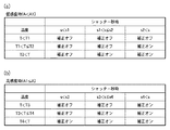
図3は、本第1の実施形態におけるノイズ補正ON/OFFテーブル171の一例を示す表である。 FIG. 3 is a table showing an example of the noise correction ON / OFF table 171 in the first embodiment.
ノイズ補正ON/OFFテーブル171は、図3に示すように、温度(T)とシャッター秒時(s)と感度(A)の3つの撮影パラメータを条件として、補正のオンまたはオフを返すように記述されたルックアップテーブルである。 As shown in FIG. 3, the noise correction ON / OFF table 171 returns correction ON / OFF on condition of three shooting parameters of temperature (T), shutter speed (s), and sensitivity (A). This is a described lookup table.
制御部17は、測定した温度と、設定された感度及びシャッター秒時に対応するノイズ補正ON/OFFテーブル171の領域を参照することで、補正のオン/オフの判断を即座に行うことができる。
The
図3に示すノイズ補正ON/OFFテーブル171の例では、感度(A)の値によって、(a)、(b)の2つの表に分割して構成されている。すなわち、感度の閾値A1を基準として、低感度(A<A1)の場合には図3(a)が適用され、高感度(A1≦A)の場合には図3(b)が適用される。 The example of the noise correction ON / OFF table 171 shown in FIG. 3 is divided into two tables (a) and (b) according to the value of sensitivity (A). That is, with reference to the sensitivity threshold A1, FIG. 3A is applied when the sensitivity is low (A <A1), and FIG. 3B is applied when the sensitivity is high (A1 ≦ A). .
また、温度は、閾値(T1、T2、T3、T4)(第1の閾値)により3つの領域に分けられ、シャッター秒時は、閾値(s1、s2、s3、s4)(第2の閾値)により同じく3つの領域に分けられている。感度、温度、シャッター秒時それぞれの閾値は、本第1の実施形態では、クロストークノイズと、撮像素子の固定パターンノイズとの視感上のバランスポイントに設定される。 Further, the temperature is divided into three regions by threshold values (T1, T2, T3, T4) (first threshold value), and threshold values (s1, s2, s3, s4) (second threshold value) at the time of shutter seconds. Are also divided into three regions. In the first embodiment, the threshold values for sensitivity, temperature, and shutter speed are set as a balance point on the sensation of crosstalk noise and fixed pattern noise of the image sensor.
ノイズ補正ON/OFFテーブル171は、通常、クロストークノイズ等による縦線ノイズが目立ち難い低感度条件時(A<A1)には補正がオンし難く、縦線ノイズが目立ち易い高感度条件時(A1≦A)には補正がオンし易いように設計されている。 The noise correction ON / OFF table 171 is normally in a low sensitivity condition where vertical line noise due to crosstalk noise or the like is not noticeable (A <A1), and correction is difficult to turn on, and in a high sensitivity condition where vertical line noise is noticeable ( A1 ≦ A) is designed so that the correction is easily turned on.
また、クロストークノイズ補正はS/N比の劣化の要因となる。そのため、ノイズ補正ON/OFFテーブル171を、通常、撮像素子の固定パターンノイズが小さく、もともとS/N比が良い、シャッター秒時が短く、且つ温度が低い条件において、補正がオンし難くなるように設計する。反対に、固定パターンノイズが大きくなるような条件、即ち、シャッター秒時が長く、且つ温度が高い条件において、補正がオンし易いように設計する。 Further, the crosstalk noise correction causes a deterioration of the S / N ratio. For this reason, the noise correction ON / OFF table 171 is usually set so that correction is difficult to turn on under conditions where the fixed pattern noise of the image sensor is small, the S / N ratio is originally good, the shutter time is short, and the temperature is low. To design. On the contrary, the correction is designed so that the correction is easily turned on under the condition that the fixed pattern noise becomes large, that is, the condition where the shutter time is long and the temperature is high.
次に、ステップS105で行われる縦線ノイズの補正処理の一例について、図4を参照して説明する。 Next, an example of vertical line noise correction processing performed in step S105 will be described with reference to FIG.
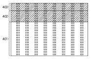
図4は、縦線ノイズ補正の動作を説明するために、撮像素子12の画素部と、撮像素子12から読み出された画像信号における縦線ノイズとの対応を示す模式図である。
FIG. 4 is a schematic diagram illustrating the correspondence between the pixel portion of the
OB部402またはダミー画素部403(撮像素子12に蓄積信号がない状態で読み出した時に発生する信号)の信号を測定することにより、撮像素子12の有効画素部401に発生するクロストークノイズのレベルを測定することが可能である。
The level of crosstalk noise generated in the
縦線ノイズは、垂直転送部の欠陥によっても発生するが、垂直転送部に印加された垂直転送パルスのそれぞれの立ち上がり、立下りのタイミングで発生するクロストークノイズによっても発生することは既に説明したとおりである。 As described above, the vertical line noise is also generated by a defect in the vertical transfer unit, but is also generated by crosstalk noise generated at the rising and falling timings of the vertical transfer pulse applied to the vertical transfer unit. It is as follows.
図4に示すように、上記の発生原因により、有効画素部401には、同じ複数列において同レベルの浮き(または沈み)が発生する。この同列で発生する同レベルの浮き(または沈み)は、OB部402及びダミー画素部403でも同様に発生する。
As shown in FIG. 4, due to the above-mentioned cause, the
本第1の実施形態では、このOB部402から出力される画像信号のそれぞれの列の加算平均値を求めて、有効画素部401の列から減算することにより、縦線ノイズの補正を行う。
In the first embodiment, the vertical line noise is corrected by obtaining the addition average value of each column of the image signal output from the
なお、上述した縦線ノイズの補正方法は一例であり、本願発明は縦線ノイズの補正方法に限定されるものではなく、公知の方法を用いることが可能である。 The vertical line noise correction method described above is merely an example, and the present invention is not limited to the vertical line noise correction method, and a known method can be used.
以上説明したように、本発明の第1の実施形態によれば、撮影時の温度、感度、シャッター秒時に基づいて縦線ノイズ補正の有無を制御することで、クロストークノイズを目立たなくすることができる。 As described above, according to the first embodiment of the present invention, crosstalk noise is made inconspicuous by controlling the presence or absence of vertical line noise correction based on the temperature, sensitivity, and shutter time at the time of shooting. Can do.
<第2の実施形態>
次に、本発明の第2の実施形態について説明する。
<Second Embodiment>
Next, a second embodiment of the present invention will be described.
上述した第1の実施形態に示したOB部402の画像信号の列毎の加算平均値を減算することによる縦線ノイズ補正は、S/N比の劣化の要因となるため、縦線ノイズのあまり目立たない低感度条件においては行わない。
The vertical line noise correction by subtracting the addition average value for each column of the image signal of the
しかし、最近では、撮像素子の高精細化とそれによる画素の微小化が進み、素子感度が低下したため、低感度条件においてもゲインアンプの増幅度をある程度高く設定せざるを得ない状況も多い。 However, recently, since the image sensor has become more precise and the size of the pixels has been reduced, the sensitivity of the device has been lowered. Therefore, there are many situations in which the gain amplifier has to be set to a high degree of amplification even under low sensitivity conditions.
本第2の実施形態は、このような素子感度のあまり高くないCCDを用いた撮像装置においても、スルーレートの低下やS/N比の劣化を伴わずに縦線ノイズが目立ちにくくなるように、垂直転送レジスタに垂直転送パルスを印加することを特徴とする。 In the second embodiment, even in an image pickup apparatus using a CCD with such a low device sensitivity, vertical line noise is less noticeable without a decrease in slew rate or a deterioration in S / N ratio. A vertical transfer pulse is applied to the vertical transfer register.
以下、本発明に係る第2の実施形態について図面を参照して詳細に説明する。なお、本第2の実施形態における撮像装置は、第1の実施形態で説明した図1と同様の構成を有し、また、撮像素子12は、図9と同様の構成を有するため、ここでは説明を省略する。
Hereinafter, a second embodiment according to the present invention will be described in detail with reference to the drawings. Note that the imaging apparatus according to the second embodiment has the same configuration as that of FIG. 1 described in the first embodiment, and the
図5は、本第2の実施形態における垂直転送レジスタ(VCCD2、第1の転送部)の駆動方法を説明するためのタイミング図である。 FIG. 5 is a timing chart for explaining a method of driving the vertical transfer register (VCCD2, first transfer unit) in the second embodiment.
本第2の実施形態では、VCCD2に印加される垂直転送パルスV1、V2、V3、V4の立ち上がり及び立ち下がりのタイミングを水平ライン毎に変えることを特徴とする。つまり、HCCD3(第2の転送部)に印加される水平転送パルスH1、H2による水平転送の開始タイミングに対して、水平ライン毎に異なるタイミングで不規則にシフトしながら垂直転送パルスを印加する。以降、この垂直駆動方式を「ランダムV駆動」と呼ぶ。 The second embodiment is characterized in that the rising and falling timings of the vertical transfer pulses V1, V2, V3, and V4 applied to the VCCD 2 are changed for each horizontal line. That is, the vertical transfer pulse is applied while being irregularly shifted at different timings for each horizontal line with respect to the horizontal transfer start timing by the horizontal transfer pulses H1 and H2 applied to the HCCD 3 (second transfer unit). Hereinafter, this vertical driving method is referred to as “random V driving”.
すなわち、水平転送パルスH1、H2による水平転送の開始タイミングから垂直駆動パルスV1の立ち上がりまでの時間を、図5に示すように、タイミングジェネレータ14によって遅延時間(Δt+td)として生成する。Δtは、水平ライン毎に固定された同じ値の遅延時間であり、これに加えられる時間tdはライン毎にランダムに値の切り変わる遅延時間である。このとき、垂直転送パルスV1、V2、V3、V4の間の立ち上がり及び立ち下がりの相対的なタイミング位相は、水平ライン間で変わらないようにする。
That is, the time from the horizontal transfer start timing by the horizontal transfer pulses H1 and H2 to the rise of the vertical drive pulse V1 is generated as a delay time (Δt + td) by the
ランダムV駆動は、垂直転送パルスV1、V2、V3、V4の立ち上がり、立下りのタイミングで撮像信号に重畳するクロストークノイズを、水平ライン毎に不規則に水平位置にシフトして散らすことで、縦線ノイズを視覚上、目立ち難くする駆動方法である。 In random V drive, crosstalk noise superimposed on the imaging signal at the rising and falling timings of the vertical transfer pulses V1, V2, V3, and V4 is randomly shifted to the horizontal position for each horizontal line and scattered. This is a driving method that makes the vertical line noise inconspicuous visually.
図6は、撮像素子12の画素部と、撮像素子12から読み出された画像信号における縦線ノイズとの対応を示す模式図である。
FIG. 6 is a schematic diagram illustrating a correspondence between the pixel portion of the
図6で示すように、ランダムV駆動によるクロストークノイズは、ノイズが一定時間幅tdの間で水平位置でランダムに分布する。そのため、縦線ノイズの幅は拡がるものの、薄くなるため、図4に示すように通常のV駆動時に発生する縦線ノイズと比較して目立ち難くなる。 As shown in FIG. 6, the crosstalk noise caused by random V driving is randomly distributed at horizontal positions within a certain time width td. For this reason, although the width of the vertical line noise is widened, it becomes thin, so that it becomes inconspicuous as compared with the vertical line noise generated during normal V driving as shown in FIG.
そのため、ランダムV駆動は、クロストークノイズに対して、ある程度の軽減効果が得られる。それでもなお高感度設定の条件化においては、縦にすじむら状のノイズとして顕在化してしまう。 Therefore, the random V drive can provide a certain degree of reduction effect on the crosstalk noise. Nevertheless, under the condition of setting the high sensitivity, it becomes obvious as vertical noise.
そこで、本発明に係る第2の実施形態においては、クロストークによる縦線ノイズに対して、それぞれの条件において最適な軽減効果が得られるように、縦線ノイズ補正とランダムV駆動とを行うように制御する。 Therefore, in the second embodiment according to the present invention, vertical line noise correction and random V driving are performed so that an optimal reduction effect can be obtained under each condition for vertical line noise due to crosstalk. To control.
図7は、本第2の実施形態における撮影処理の流れを示すフローチャートである。なお、ここでは、静止画撮影の場合について説明するが、動画撮影やライブビューモードにおいても、同様の処理により同様の効果をあげることができる。 FIG. 7 is a flowchart showing a flow of photographing processing in the second embodiment. Although the case of still image shooting will be described here, the same effect can be obtained by similar processing also in moving image shooting and live view mode.
まず、不図示のシャッタボタンの押下などに応じて、静止画の撮影を開始する。なお、撮影開始時には撮影データとして感度、絞り値、シャッター秒時を含む撮影条件を公知の方法により取得して記憶領域19に記憶しておく。そして、制御部17の制御により、記憶領域19の撮影データから感度、絞り値、シャッター秒時等の撮影露出条件と、サーミスタ18により得られる撮像素子12の周辺温度とを含む一連の撮影パラメータを取得する(ステップS202)。
First, shooting of a still image is started in response to pressing of a shutter button (not shown). At the start of shooting, shooting conditions including sensitivity, aperture value, and shutter speed are acquired as shooting data by a known method and stored in the
次に、制御部17の不図示の内部メモリに記憶されたノイズ補正ON/OFFテーブル171を参照して、クロストークノイズを含む縦線ノイズの補正を行うかどうかを判断する(ステップS203)。
Next, with reference to a noise correction ON / OFF table 171 stored in an internal memory (not shown) of the
そして、ノイズ補正ON/OFFテーブル171に従い、補正を行わない場合には、制御部17はタイミングジェネレータ14を制御して、ランダムV駆動を行うように設定する(ステップS204)。そして、撮影パラメータに基づく撮像装置10に対する露出の設定から、ランダムV駆動による撮像素子12の駆動及び読み出し、そして記憶領域20への画像データの書き込みまでの一連の動作を含めた撮影処理を行う(ステップS205)。そして、記憶領域20に記憶された画像データを補正せずにそのまま記録媒体16に記録する(ステップS209)。
Then, according to the noise correction ON / OFF table 171, when the correction is not performed, the
一方、ステップS203において、ノイズ補正ON/OFFテーブル171に従って補正を行うと判断した場合には、ステップS206に進む。ステップS206では、制御部17はタイミングジェネレータ14を制御して、ランダムV駆動ではない、図9に示す駆動方法(ここでは、「固定V駆動」と呼ぶ。)により撮像素子12を駆動するように設定する。そして、撮影パラメータに基づく撮像装置10に対する露出の設定から、設定した固定駆動方法による撮像素子12の駆動及び読み出し、そして記憶領域20への画像データの書き込みまでの一連の動作を含めた撮影処理を行う(ステップS207)。
On the other hand, if it is determined in step S203 that correction is performed according to the noise correction ON / OFF table 171, the process proceeds to step S206. In step S206, the
そして、記憶領域20内の画像データに対してクロストークノイズを含む縦線ノイズ補正を行い(ステップS208)、補正後の画像データを記憶領域20に再び記憶する。なお、縦線ノイズ補正は、例えば、上述した第1の実施形態と同様の方法で補正を行えばよい。そして、ステップS106に進んで、記憶領域20に記憶された補正後の画像データを記録媒体16に記録する。
Then, vertical line noise correction including crosstalk noise is performed on the image data in the storage area 20 (step S208), and the corrected image data is stored in the
次に、ステップS210において、連写など撮影を継続するかどうかを判断し、継続する場合には、ステップS202に戻って上述した処理を繰り返す。一方、継続しない場合には、ここで撮影動作を終了する。 Next, in step S210, it is determined whether to continue shooting such as continuous shooting. If so, the process returns to step S202 and the above-described processing is repeated. On the other hand, when the operation is not continued, the photographing operation is terminated here.
上記の通り本発明の第2の実施形態によれば、第1の実施形態の効果に加えて、ノイズ補正を行わない場合はランダムV駆動を行うことで、クロストークノイズをより目立たなくすることができる。 As described above, according to the second embodiment of the present invention, in addition to the effects of the first embodiment, when noise correction is not performed, random V driving is performed, thereby making crosstalk noise less noticeable. Can do.
なお、上述した第1及び第2の実施形態では、VCCD2を4相駆動とし、HCCD3を2相駆動としたが、これ以外の方式のCCDにも適用可能なことは言うまでもない。
In the first and second embodiments described above, the VCCD 2 is driven in four phases and the
また、本発明では、ランダムV駆動を、HCCD3が1回の転送を行う毎に、HCCD3の転送開始タイミングに対して相対的にランダムなタイミングでVCCD2の転送動作を行う垂直駆動方法を例にあげて説明した。しかし、HCCD3の水平転送開始タイミングに対して必ずしもランダムなタイミングにする必要はない。VCCD2の垂直転送動作のタイミングをHCCD3の水平転送開始タイミングに対して単に固定から一定の水平ライン周期で可変としてもよい。そうすることで、有効画素信号に重畳するノイズの位置を変えて縦線ノイズを目立ち難くすることができる。
In the present invention, the random V drive is exemplified by a vertical drive method in which the transfer operation of the VCCD 2 is performed at a timing relatively random with respect to the transfer start timing of the
また、上述した第1及び第2の実施形態では、主として静止画撮影を例に説明した。しかし、画素の加算や間引きなど、撮像素子の画素部の読み出し方法に違いは有っても、静止画撮影の処理フローを連続的に繰り返すことで、動画撮影やライブビューモードにおいても、同様の構成で同様の効果が得られる。 In the above-described first and second embodiments, still image shooting has been mainly described as an example. However, even if there is a difference in the readout method of the pixel part of the image sensor, such as pixel addition and thinning, the same processing can be performed in video shooting and live view mode by continuously repeating the still image shooting process flow. The same effect can be obtained with the configuration.
また、上述した第1及び第2の実施形態では、撮像装置において本願発明を実施する場合について説明した。しかしながら、第1の実施形態で説明した縦線ノイズ補正制御は、撮像装置から画像データを受け取った画像処理装置において行うことも可能である。その場合、画像処理装置においてノイズ補正ON/OFFテーブルを記憶しておき、撮像装置で取得したノイズ補正前の画像データ及び撮影パラメータを画像処理装置に入力し、画像処理装置においてノイズ補正処理を行えばよい。 In the above-described first and second embodiments, the case where the present invention is implemented in the imaging apparatus has been described. However, the vertical line noise correction control described in the first embodiment can also be performed in the image processing apparatus that has received the image data from the imaging apparatus. In that case, the noise correction ON / OFF table is stored in the image processing apparatus, the image data before the noise correction acquired by the imaging apparatus and the shooting parameters are input to the image processing apparatus, and the noise correction processing is performed in the image processing apparatus. Just do it.
<他の実施形態>
なお、本発明は、複数の機器(例えばホストコンピュータ、インターフェイス機器、カメラなど)から構成されるシステムに適用しても、一つの機器からなる装置(例えば、デジタルカメラなど)に適用してもよい。
<Other embodiments>
The present invention may be applied to a system constituted by a plurality of devices (for example, a host computer, an interface device, a camera, etc.), or may be applied to an apparatus (for example, a digital camera, etc.) comprising a single device. .
また、本発明の目的は、以下の様にして達成することも可能である。まず、前述した実施形態の機能を実現するソフトウェアのプログラムコードを記録した記憶媒体(または記録媒体)を、システムあるいは装置に供給する。そして、そのシステムあるいは装置のコンピュータ(またはCPUやMPU)が記憶媒体に格納されたプログラムコードを読み出し実行する。この場合、記憶媒体から読み出されたプログラムコード自体が前述した実施形態の機能を実現することになり、そのプログラムコードを記憶した記憶媒体は本発明を構成することになる。 The object of the present invention can also be achieved as follows. First, a storage medium (or recording medium) that records a program code of software that implements the functions of the above-described embodiments is supplied to a system or apparatus. Then, the computer (or CPU or MPU) of the system or apparatus reads and executes the program code stored in the storage medium. In this case, the program code itself read from the storage medium realizes the functions of the above-described embodiments, and the storage medium storing the program code constitutes the present invention.
また、コンピュータが読み出したプログラムコードを実行することにより、前述した実施形態の機能が実現されるだけでなく、以下のようにして達成することも可能である。即ち、読み出したプログラムコードの指示に基づき、コンピュータ上で稼働しているオペレーティングシステム(OS)などが実際の処理の一部または全部を行い、その処理によって前述した実施形態の機能が実現される場合である。ここでプログラムコードを記憶する記憶媒体としては、例えば、フレキシブルディスク、ハードディスク、ROM、RAM、磁気テープ、不揮発性のメモリカード、CD−ROM、CD−R、DVD、光ディスク、光磁気ディスク、MOなどが考えられる。また、LAN(ローカル・エリア・ネットワーク)やWAN(ワイド・エリア・ネットワーク)などのコンピュータネットワークを、プログラムコードを供給するために用いることができる。 Further, by executing the program code read by the computer, not only the functions of the above-described embodiments are realized, but also the following can be achieved. That is, when the operating system (OS) running on the computer performs part or all of the actual processing based on the instruction of the read program code, the functions of the above-described embodiments are realized by the processing. It is. Examples of the storage medium for storing the program code include a flexible disk, hard disk, ROM, RAM, magnetic tape, nonvolatile memory card, CD-ROM, CD-R, DVD, optical disk, magneto-optical disk, MO, and the like. Can be considered. Also, a computer network such as a LAN (Local Area Network) or a WAN (Wide Area Network) can be used to supply the program code.
10:撮像装置
11:レンズ
12:撮像素子(CCD)
13:画像処理回路
14:タイミングジェネレータ
15:記憶部(RAM)
16:記録媒体
17:制御部(CPU)
18:サーミスタ
19:撮影データの記憶領域
20:画像データの記憶領域
171:ノイズ補正ON/OFFテーブル
10: Imaging device 11: Lens 12: Imaging device (CCD)
13: Image processing circuit 14: Timing generator 15: Storage unit (RAM)
16: Recording medium 17: Control unit (CPU)
18: Thermistor 19: Image data storage area 20: Image data storage area 171: Noise correction ON / OFF table
Claims (8)
前記光電変換素子で発生した電荷信号を列方向に転送する第1の転送部と、
前記第1の転送部により転送された電荷信号を行方向に転送する第2の転送部と、
前記第2の転送部による電荷信号の転送中に、前記第1の転送部を駆動する駆動手段と、
前記第2の転送部から出力された電荷信号について、前記第1の転送部の駆動に起因して発生するノイズを含むノイズを補正するノイズ補正手段と、
感度、シャッター秒時、及び温度の少なくとも1つに基づいて、前記ノイズ補正手段によるノイズの補正を行うか否かを制御する制御手段とを有し、
前記制御手段は、前記ノイズ補正手段によるノイズの補正を行わない場合に、前記第2の転送部が、1回の転送で前記第1の転送部から前記第2の転送部に転送された電荷信号を出力する毎に、前記第1の転送部を駆動するためのパルスを出力するタイミングをシフトするように前記駆動手段を制御することを特徴とする撮像装置。 Photoelectric conversion elements arranged two-dimensionally in a row direction and a column direction;
A first transfer unit that transfers a charge signal generated in the photoelectric conversion element in a column direction;
A second transfer unit that transfers the charge signal transferred by the first transfer unit in a row direction;
Driving means for driving the first transfer unit during transfer of the charge signal by the second transfer unit ;
Noise correction means for correcting noise including noise generated due to driving of the first transfer unit with respect to the charge signal output from the second transfer unit;
Control means for controlling whether to perform noise correction by the noise correction means based on at least one of sensitivity, shutter speed, and temperature ,
When the control unit does not perform noise correction by the noise correction unit, the second transfer unit transfers the charge transferred from the first transfer unit to the second transfer unit in one transfer. An image pickup apparatus that controls the driving unit so as to shift a timing of outputting a pulse for driving the first transfer unit every time a signal is output.
制御手段が、前記撮像装置の感度、シャッター秒時、及び温度の少なくとも1つに基づいて、前記第1の転送部の駆動に起因して発生するノイズを含むノイズの補正を行うか否かを判断する判断工程と、
ノイズ補正手段が、前記ノイズの補正を行うと判断された場合に、前記第2の転送部から出力された電荷信号についてノイズを補正するノイズ補正工程と、
前記制御手段が、前記ノイズの補正を行わないと判断された場合に、前記第2の転送部が、1回の転送で前記第1の転送部から前記第2の転送部に転送された電荷信号を出力する毎に、前記第1の転送部を駆動するためのパルスを出力するタイミングをシフトするように前記駆動手段を制御する制御工程と
を有することを特徴とする制御方法。 First a transfer unit, the first charge signal transferred by the transfer unit for transferring the photoelectric conversion elements arranged two-dimensionally in a row direction and a column direction, charge signals generated in the photoelectric conversion elements in the column direction A second transfer unit that transfers the first transfer unit in a row direction, and a drive unit that drives the first transfer unit during transfer of the charge signal by the second transfer unit,
Whether the control means corrects noise including noise generated due to driving of the first transfer unit based on at least one of sensitivity, shutter speed, and temperature of the imaging device. A judging process for judging;
A noise correction step of correcting noise for the charge signal output from the second transfer unit when it is determined that the noise correction unit corrects the noise;
The charge transferred from the first transfer unit to the second transfer unit in one transfer by the second transfer unit when it is determined that the control unit does not correct the noise. control method characterized by each for outputting a signal, and a control step of controlling said drive means so as to shift the timing of outputting a pulse for driving the first transfer portion.
Priority Applications (2)
| Application Number | Priority Date | Filing Date | Title |
|---|---|---|---|
| JP2008122775A JP5258372B2 (en) | 2008-05-08 | 2008-05-08 | Imaging apparatus and control method thereof |
| US12/431,406 US8558934B2 (en) | 2008-05-08 | 2009-04-28 | Image sensing apparatus and control method therefor, and image processing apparatus and reduction method |
Applications Claiming Priority (1)
| Application Number | Priority Date | Filing Date | Title |
|---|---|---|---|
| JP2008122775A JP5258372B2 (en) | 2008-05-08 | 2008-05-08 | Imaging apparatus and control method thereof |
Publications (3)
| Publication Number | Publication Date |
|---|---|
| JP2009272967A JP2009272967A (en) | 2009-11-19 |
| JP2009272967A5 JP2009272967A5 (en) | 2011-06-23 |
| JP5258372B2 true JP5258372B2 (en) | 2013-08-07 |
Family
ID=41266550
Family Applications (1)
| Application Number | Title | Priority Date | Filing Date |
|---|---|---|---|
| JP2008122775A Expired - Fee Related JP5258372B2 (en) | 2008-05-08 | 2008-05-08 | Imaging apparatus and control method thereof |
Country Status (2)
| Country | Link |
|---|---|
| US (1) | US8558934B2 (en) |
| JP (1) | JP5258372B2 (en) |
Families Citing this family (3)
| Publication number | Priority date | Publication date | Assignee | Title |
|---|---|---|---|---|
| JP5975795B2 (en) * | 2012-08-29 | 2016-08-23 | キヤノン株式会社 | Imaging apparatus and driving method thereof |
| WO2019037022A1 (en) * | 2017-08-24 | 2019-02-28 | 深圳市大疆创新科技有限公司 | Image processing method and device, and unmanned aerial vehicle |
| WO2020039780A1 (en) | 2018-08-24 | 2020-02-27 | ソニー株式会社 | Image-capturing device and power supply control method |
Family Cites Families (10)
| Publication number | Priority date | Publication date | Assignee | Title |
|---|---|---|---|---|
| JPS6229374A (en) * | 1985-07-31 | 1987-02-07 | Canon Inc | Solid-state image pickup device |
| JP3715781B2 (en) | 1997-04-02 | 2005-11-16 | キヤノン株式会社 | Imaging device |
| US6476941B1 (en) | 1997-04-02 | 2002-11-05 | Canon Kabushiki Kaisha | Solid-state image sensing device and operation method thereof |
| JP4365460B2 (en) * | 1998-07-15 | 2009-11-18 | オリンパス株式会社 | Imaging device |
| JP2002010144A (en) * | 2000-06-16 | 2002-01-11 | Canon Inc | Device for driving image pickup element and method therefor and picture processor |
| JP2005045552A (en) * | 2003-07-22 | 2005-02-17 | Canon Inc | Imaging device and its method |
| JP4277718B2 (en) | 2004-03-17 | 2009-06-10 | ソニー株式会社 | CCD solid-state imaging device and driving method thereof |
| JP4763375B2 (en) * | 2004-08-24 | 2011-08-31 | パナソニック株式会社 | Imaging apparatus and image data correction method |
| JP4453640B2 (en) * | 2005-09-30 | 2010-04-21 | ソニー株式会社 | Driving method and driving apparatus for driving semiconductor device having capacitive load, and electronic apparatus |
| JP4453034B2 (en) * | 2006-01-13 | 2010-04-21 | ソニー株式会社 | Transfer pulse generation circuit and imaging device |
-
2008
- 2008-05-08 JP JP2008122775A patent/JP5258372B2/en not_active Expired - Fee Related
-
2009
- 2009-04-28 US US12/431,406 patent/US8558934B2/en not_active Expired - Fee Related
Also Published As
| Publication number | Publication date |
|---|---|
| US8558934B2 (en) | 2013-10-15 |
| US20090278970A1 (en) | 2009-11-12 |
| JP2009272967A (en) | 2009-11-19 |
Similar Documents
| Publication | Publication Date | Title |
|---|---|---|
| JP5852324B2 (en) | Imaging apparatus, control method therefor, and program | |
| JP5614993B2 (en) | Imaging apparatus and solid-state imaging device driving method | |
| JP5203913B2 (en) | Photoelectric conversion device, imaging system, and driving method of photoelectric conversion device | |
| US8422819B2 (en) | Image processing apparatus having a noise reduction technique | |
| US7907193B2 (en) | Image capturing apparatus | |
| JP2008042679A (en) | Photoelectric conversion device and imaging apparatus | |
| JP5013812B2 (en) | Imaging apparatus and correction method | |
| US7277128B2 (en) | Image-sensing device having a plurality of output channels | |
| JP2007329658A (en) | Imaging apparatus and driving method therefor | |
| US8169494B2 (en) | Image sensing apparatus and method of controlling image sensing apparatus | |
| JP5258372B2 (en) | Imaging apparatus and control method thereof | |
| JP2005175930A (en) | Image pickup device, its signal processing method, and image pickup system | |
| JP2009130383A (en) | Image device | |
| JP2010093759A (en) | Imaging sensor and imaging apparatus | |
| JP2009100283A (en) | Imaging apparatus and control method for imaging apparatus | |
| JP5222029B2 (en) | IMAGING DEVICE, IMAGING SYSTEM, AND IMAGING DEVICE CONTROL METHOD | |
| JP2006222762A (en) | Imaging apparatus | |
| JP2005286470A (en) | Imaging unit | |
| JP2011009834A (en) | Imager and imaging method | |
| JP2008072512A (en) | Photographing apparatus and its control method, and photographing system | |
| JP2009188650A (en) | Imaging apparatus | |
| JP4991415B2 (en) | Imaging device | |
| JP7020463B2 (en) | Imaging device | |
| JP2010166479A (en) | Imaging device and method of correcting imaged image | |
| JP2008295007A (en) | Imaging device and control method therefor |
Legal Events
| Date | Code | Title | Description |
|---|---|---|---|
| A521 | Request for written amendment filed |
Free format text: JAPANESE INTERMEDIATE CODE: A523 Effective date: 20110506 |
|
| A621 | Written request for application examination |
Free format text: JAPANESE INTERMEDIATE CODE: A621 Effective date: 20110506 |
|
| A977 | Report on retrieval |
Free format text: JAPANESE INTERMEDIATE CODE: A971007 Effective date: 20120905 |
|
| A131 | Notification of reasons for refusal |
Free format text: JAPANESE INTERMEDIATE CODE: A131 Effective date: 20120910 |
|
| A521 | Request for written amendment filed |
Free format text: JAPANESE INTERMEDIATE CODE: A523 Effective date: 20121106 |
|
| TRDD | Decision of grant or rejection written | ||
| A01 | Written decision to grant a patent or to grant a registration (utility model) |
Free format text: JAPANESE INTERMEDIATE CODE: A01 Effective date: 20130325 |
|
| A61 | First payment of annual fees (during grant procedure) |
Free format text: JAPANESE INTERMEDIATE CODE: A61 Effective date: 20130423 |
|
| FPAY | Renewal fee payment (event date is renewal date of database) |
Free format text: PAYMENT UNTIL: 20160502 Year of fee payment: 3 |
|
| R151 | Written notification of patent or utility model registration |
Ref document number: 5258372 Country of ref document: JP Free format text: JAPANESE INTERMEDIATE CODE: R151 |
|
| LAPS | Cancellation because of no payment of annual fees |