JP5249593B2 - Resist solution recovery method - Google Patents
Resist solution recovery method Download PDFInfo
- Publication number
- JP5249593B2 JP5249593B2 JP2008016150A JP2008016150A JP5249593B2 JP 5249593 B2 JP5249593 B2 JP 5249593B2 JP 2008016150 A JP2008016150 A JP 2008016150A JP 2008016150 A JP2008016150 A JP 2008016150A JP 5249593 B2 JP5249593 B2 JP 5249593B2
- Authority
- JP
- Japan
- Prior art keywords
- resist solution
- container
- recovery
- spout
- opening
- Prior art date
- Legal status (The legal status is an assumption and is not a legal conclusion. Google has not performed a legal analysis and makes no representation as to the accuracy of the status listed.)
- Active
Links
Images


Description
本発明は、使用済レジスト液の回収方法に関し、更に詳しくは、レジスト液を、レジスト塗布装置を備える使用施設に供給し、塗布後の使用済レジスト液を回収してリサイクルなどに利用する方法に関する。 The present invention relates to a method for recovering a used resist solution, and more specifically, relates to a method for supplying a resist solution to a use facility equipped with a resist coating apparatus, and recovering the used resist solution after application and using it for recycling or the like. .
半導体や液晶パネルなどの製造プロセスにおいては、基板上にレジスト液を塗布して露光現像するリソグラフィが行われる。近年の液晶パネル等の大型化に伴い、使用する基板も大型化が進んでいることからレジスト液の使用量も増大している。代表的な塗布方式にはスピンコート方式やダイコート(スリットコート)方式がある。 In a manufacturing process of a semiconductor, a liquid crystal panel, etc., lithography is performed in which a resist solution is applied onto a substrate and exposed and developed. With the recent increase in size of liquid crystal panels and the like, the amount of resist solution used has also increased because the size of the substrate used has been increased. Typical coating methods include a spin coating method and a die coating (slit coating) method.
基板へのレジスト液の塗布においては、実際の塗布量以上の過剰量のレジスト液が必要になることから、余剰の使用済レジスト液が常に発生する。特にスピンコートを用いる際には使用済レジスト液は無視できない量であるため、その有効利用として回収してリサイクル利用することが、経済的、環境的にも望まれる。 In applying the resist solution to the substrate, an excessive amount of resist solution larger than the actual application amount is required, so that an excessive used resist solution is always generated. In particular, when using spin coating, the amount of used resist solution is not negligible. Therefore, it is economically and environmentally desirable to recover and recycle it as an effective use.
このようなレジスト液の回収やリサイクルに関しては、下記の特許文献1、2のような回収装置が知られている。このシステムは、レジスト液塗布装置自体に回収、再生装置を付設し、粘度調整やフィルターろ過によりレジスト液のリサイクルを行うものである。
With respect to such recovery and recycling of the resist solution, recovery devices such as those in
また、この他に、複数のレジスト液塗布装置を備える施設内に、共通の大掛かりな回収ラインを設置して、複数の塗布装置からの使用済レジスト液をタンク等に一括回収し、これをレジストメーカーに返送して、レジストメーカー側でリサイクルすることも行われている。 In addition to this, a common large collection line is installed in a facility equipped with a plurality of resist solution coating devices, and used resist solutions from a plurality of coating devices are collectively collected in a tank or the like. It is also sent back to the manufacturer and recycled by the resist manufacturer.
一方、半導体メーカーや液晶パネルメーカーなどのユーザーへのレジスト液の供給は、レジストメーカーから通常行われる。この場合、例えば、特許文献3に記載されているような所定容量の小型の専用容器が用いられている。この専用容器は、小型の剛性容器と、その内部に着脱可能なフレキシブル材料からなる内袋の二重構造になっている。このような専用容器は、そのままユーザーのラインに直結させることができ、且つ、取り扱いが手軽で、また、レジスト液への異物混入の危険性が少ないために主流となっている。この専用容器は、内袋にレジスト液が充填された状態でユーザーに納入され、ユーザーで塗布装置などのラインに直結して使用され、使用済み(内袋が空袋)になった後に、そのまま回収されてレジストメーカーなどに返却され、清掃等を施した後、再度レジスト液の充填を行う、いわゆる通い容器として用いられている。
特許文献1や2のようなレジスト液回収システムは、基本的にユーザー側でのリサイクルを念頭に置いたものである。この場合、リサイクルしたレジスト液の品質管理はユーザー側で行う必要があり、レジスト液に熟知していないユーザー側が上記の品質管理を安定的に行うことは困難である。
The resist solution recovery systems such as
また、複数の塗布装置からの使用済レジスト液をタンク等に一括回収し、これをレジスト液メーカーに返送する方法は、ユーザー側に回収設備を設置する必要があり、設備的な負担や管理的な負担が新たに発生するという問題がある。 Also, the method of collecting the used resist solution from multiple coating devices in a tank etc. and returning it to the resist solution maker requires the installation of a collection facility on the user side. There is a problem that a new burden is generated.
また、特許文献3の専用容器は、あくまでレジスト液の供給専用容器であり、汲み出し終了後に使用済レジスト液を再充填することなどは全く想定されておらず、このままでは回収容器として使用することができない。 In addition, the dedicated container of Patent Document 3 is only a resist solution supply container, and it is not assumed that the used resist solution is refilled after the pumping is finished. Can not.
本発明者らは、上記の問題を解決すべく鋭意検討した結果、従来、レジスト液の供給専用容器として用いられていた通い容器を、レジスト液の回収容器としても利用し、供給兼回収容器として使用することで、上記の問題点を解決することができることを見出し、本発明を完成するに至った。 As a result of intensive studies to solve the above problems, the present inventors have also used a conventional container used as a resist solution supply container as a resist solution recovery container as a supply and recovery container. By using it, it discovered that said problem could be solved, and came to complete this invention.
すなわち、本発明は、所定容量の専用容器を用いてレジスト液供給施設からレジスト液使用施設へレジスト液を供給するとともに、この専用容器を、前記レジスト液使用施設における使用済レジスト液を回収するためのレジスト液回収容器としても使用するレジスト液回収方法である。 That is, the present invention supplies a resist solution from a resist solution supply facility to a resist solution use facility using a dedicated container having a predetermined capacity, and collects the used resist solution at the resist solution use facility using the dedicated container. This resist solution recovery method is also used as a resist solution recovery container.
本発明の特徴は、従来、レジスト液の供給専用容器として用いられていたものを供給兼回収容器として使用するものである。この点、本発明は新たなレジスト液回収方法を提供するものであるとともに、従来の供給専用容器に新たな回収という用途を見出したものとも言える。 A feature of the present invention is that what has been conventionally used as a resist solution supply container is used as a supply and recovery container. In this respect, the present invention provides a new method for recovering a resist solution, and can be said to have found a new use for recovery in a conventional supply-only container.
本発明によれば、通い容器を用いた既存のレジスト液供給システムをそのまま用いることができる。従って、ユーザー側では特段の回収設備やリサイクル設備を設ける必要がない。このためユーザー側における設備面の自由度が高い。具体的には、既存のレジスト液塗布装置のライン配置に起因してスペース的にレジスト液回収設備を設置できない場合などに本発明を効果的に用いることができる。 According to the present invention, an existing resist solution supply system using a returnable container can be used as it is. Therefore, it is not necessary for the user to provide special recovery equipment or recycling equipment. For this reason, the degree of freedom of equipment on the user side is high. Specifically, the present invention can be effectively used when the resist solution recovery equipment cannot be installed in a space due to the line arrangement of the existing resist solution coating apparatus.
また、既存のレジスト液供給システムをそのまま用いて回収ができるため、複数の塗布装置からの使用済レジスト液をタンク等に一括回収し、これをレジスト液メーカーに返送する従来の方法に比べて、回収費用と労力を大幅に削減できる。 In addition, because it can be recovered using the existing resist solution supply system as it is, compared to the conventional method of collecting the used resist solution from a plurality of coating devices in a tank and returning it to the resist solution manufacturer, Collection costs and labor can be greatly reduced.
なお、本発明における、専用容器を「レジスト液回収容器としても使用する」の意味は、専用容器が、供給と回収とを兼用できる容器であれば足りることを意味する。このため、時間的に供給作業と回収作業が近いことは要求されない。すなわち、供給に使用された専用容器が、その後に回収容器として使用されれば本発明の範囲内である。また、レジスト液塗布装置単位で見て、供給容器の種類や容量が、回収容器と異なる容器を用いている場合であっても、その供給容器が、結果としてその後にレジスト液使用施設のどこかで回収容器として使用されればやはり本発明の範囲内である。 In the present invention, the meaning of “use a dedicated container as a resist solution recovery container” in the present invention means that the dedicated container is sufficient if it can be used for both supply and recovery. For this reason, it is not required that the supply operation and the recovery operation are close in time. That is, if the exclusive container used for supply is used as a collection container after that, it is within the scope of the present invention. In addition, even if the type and capacity of the supply container is different from that of the collection container when viewed in units of resist solution coating equipment, the supply container will eventually be somewhere in the resist solution use facility. If it is used as a recovery container, it is still within the scope of the present invention.
本発明によれば、従来に比べて大幅にレジスト液の回収を効率化することができ、低コストでレジスト液を回収でき、リサイクル率を高めることができる。 According to the present invention, the recovery of the resist solution can be made much more efficient than before, the resist solution can be recovered at a low cost, and the recycling rate can be increased.
以下、本発明の好ましい一実施形態について図面を用いて詳細に説明する。図1は本発明の一例を示す工程図、図2は専用容器(供給兼回収容器)の一実施形態を示す縦断面図、図3は図2の開口部分を拡大して示す拡大断面図、図4は図2の開口部分の断面分解組立図、図5は注出口付き包装袋の外装容器への収容状態を示す図であり、(a)は注出口付き包装袋を外装容器に挿入する状態を示す部分斜視図、(b)は外装容器に注出口付き包装袋が収容された後の状態を示す部分斜視図、図6はレジスト液回収システムの一例を示す概略図である。 Hereinafter, a preferred embodiment of the present invention will be described in detail with reference to the drawings. FIG. 1 is a process diagram showing an example of the present invention, FIG. 2 is a longitudinal sectional view showing an embodiment of a dedicated container (feeding and collecting container), and FIG. 3 is an enlarged sectional view showing the opening of FIG. FIG. 4 is a sectional exploded view of the opening portion of FIG. 2, FIG. 5 is a view showing a state in which the packaging bag with spout is accommodated in the outer container, and (a) inserts the packaging bag with spout into the outer container. The partial perspective view which shows a state, (b) is a partial perspective view which shows the state after the packaging bag with a spout is accommodated in the exterior container, FIG. 6: is schematic which shows an example of a resist liquid collection | recovery system.
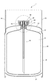
<専用容器>
まず、本発明において供給兼回収容器となる専用容器1について説明すると、図2から図4に示すように、専用容器1は、可撓性の注出口付き包装袋10と、開口部24を有する外装容器20と、開口部24に保持される円筒状の継手ブラケット30と、この継手ブラケット30の筒部32に挿入される液出しチューブ40と、開口部24に螺合して、注出口11及び継手ブラケット30を開口部24に保持する円環状の第1蓋50と、内部に突出するブッシュ62を有する第2蓋60と、を備えている。
<Dedicated container>
First, the
注出口付き包装袋10は、液体を注入可能に開口する注出口11とレジスト液を充填する包装袋本体12とを有している。注出口11は注出口取付部111と、該注出口取付部111の一方に連接する注出口係合部112とからなり、図4に示すように、注出口取付部111で包装袋本体12に熱融着されている。
The spout-equipped
外装容器20は、注出口11を開口部24で支持して、注出口付き包装袋10を収納することができる。そして、図5に示すように、注出口付き包装袋10は外装容器20内に内袋として収納される。このように、専用容器1は、外装容器20が繰り返し使用され、毎回新しい注出口付き包装袋10が使用可能な二重容器となっている。
The
外装容器20は、図2に示すように、底板21と、側壁22と、中央が隆起した天板23とで構成され、天板23の略中央部分に開口部24が形成されたスチール製容器が好ましく用いられる。開口部24の外周面に雄ねじ24aが形成されている。また、側壁22の天板23より上方位置に一対のハンド部25(図5参照)を設けることにより運搬を容易にしてもよい。外装容器20としては、例えば、金属製、合成樹脂製、段ボール等の紙製の剛性容器が例示されるが、特にこれらに限定されるものではない。
As shown in FIG. 2, the
図4に示すように、注出口付き包装袋10の注出口11の開口側にはフランジ部112bが形成され、一方、開口部24の内壁には段差が設けられており、このフランジ部112bが段差に係止することにより、注出口11が開口部24に支持されている。
As shown in FIG. 4, a
後述するレジスト液供給工程S20で使用する継手は、円筒状の継手ブラケット30と液出しチューブ40を備えている(図3又は図4参照)。図3において、継手ブラケット30は開口部24に保持されている。また、継手ブラケット30は、略筒状のヘッダ部31を一端側に有し、筒部32を他端側に有している。さらに、継手ブラケット30は、一端側から他端側に貫通する第2貫通穴33を有している。ヘッダ部31は、継手ブラケット30の円筒状底内から隆起している。筒部32は、注出口11の第1貫通穴111aに嵌合する(図3参照)。
The joint used in the resist solution supply step S20 described later includes a
図3又は図4において、液出しチューブ40は、継手ブラケット30のヘッダ部31の頂面311に密着される鍔部41を一端側に有している。また、液出しチューブ40の他端側は、継手ブラケット30の第2貫通穴33に挿入される。液出しチューブ40は、一端から他端まで延びる流体通路42を有し、注出口付き包装袋10内の液体が流体通路42を通って排出可能に構成されている(図2参照)。
In FIG. 3 or FIG. 4, the
継手ブラケット30の外径は、注出口11の内径より僅かに小さく、開口部24に支持された注出口11に継手ブラケット30が嵌合する(図3参照)。継手ブラケット30の一端側には、開口部24の内径より僅かに小さい外径を有するフランジ34が設けられ、このフランジ34にオーリングが担持され、開口部24が密封されている(図3又は図4参照)。
The outer diameter of the
継手ブラケット30は、第1蓋50が開口部24に締結されることにより、注出口11と共に開口部24に保持される(図3参照)。継手ブラケット30の底部外壁と、注出口11の筒状部112aの底部内壁との間に所定の間隙が設けられている(図3参照)。
The
図4において、筒部32は、継手ブラケット30の底部から突出するように設けられ、筒部32が注出口11の第1貫通穴111aに嵌合する。注出口11の第1貫通穴111a内部にはオーリングが担持され、このオーリングが筒部32の外周に密着することにより、注出口付き包装袋10内の気体を封止することができる(図示せず)。ヘッダ部31の上端から筒部32の下端に第2貫通穴33が貫通しており、第2貫通穴33に液出しチューブ40が挿入される(図3参照)。注出口付き包装袋10内の気体が複数の第2開口43に通気できるように、第2貫通穴33と液出しチューブ40の外周に間隙が設けられている(図3参照)。
In FIG. 4, the
継手は、外装容器20の内部から開口部24に気体を通気可能な第1通気手段と、注出口付き包装袋10の内部から開口部24に気体を通気可能な第2通気手段と、開口部24を封止する第2蓋60と、を備えている。第1通気手段は、継手ブラケット30の複数の第1開口35を有している。複数の第1開口35は、筒部32の周囲からヘッダ部31の頂面311に連通している。第2通気手段は、複数の第2開口43を有している。複数の第2開口43は、液出しチューブ40の鍔部41に設けられ、開口部24と継手ブラケット30の第2貫通穴33内部とを連通している(図3及び図4参照)。
The joint includes a first ventilation means capable of venting gas from the inside of the
そして、継手は、第2蓋60を取り付けたときは、開口部24から液体と気体のいずれも流出することを防止する。また、第2蓋60を取り除いたときは、液出しチューブ40内の液体が開口部24に排出される前に、外装容器20内の気体、及び注出口付き包装袋10内の気体がそれぞれ第1及び第2通気手段を通って開口部24外に逃げるようになっている。
The joint prevents the liquid and gas from flowing out from the
第1開口35は、筒部32の周囲からヘッダ部31の頂面311に貫通するスリットであってよく、筒部32とヘッダ部31との間に設けられる。第1開口35は、継手ブラケット30と注出口11との間に設けられる間隙と、大気とを実質的に連通している(図3及び図4参照)。
The
図3に示すように、第2開口43は、液出しチューブ40の鍔部41に形成される貫通穴であって、鍔部41の上面から液出しチューブ40の周囲に貫通している。図3において、鍔部41の下面にはオーリングが担持され、このオーリングがヘッダ部31の頂面311に密着することにより、第2貫通穴33を封止する。そして、第2開口43は、第2貫通穴33の内壁と液出しチューブ40の外壁に設けられた間隙と、大気とを実質的に連通している(図3及び図4参照)。前述したように、この間隙は注出口付き包装袋10の内部空間に通気可能となっている。
As shown in FIG. 3, the
図3又は図4において、外装容器20の開口部24と螺合する第1蓋50と該第1蓋50に螺合する第2蓋60とを備えている。第1蓋50は、内側面に外装容器20の開口部24の外面と螺合する雌ねじが形成され、外側面に雄ねじが形成された金属製又は合成樹脂製の蓋本体51に、継手ブラケット30の外寸法と略同じ寸法の第4開口52が同心円状に形成されている。第1蓋50を開口部24に螺合して締め付けることで、継手ブラケット30は保持される。
3 or 4, a
第2蓋60は、開口部24に備わる第1蓋50に螺合する遮光性を有するクロジャー本体61と、クロジャー本体61の内部に突出する耐食性を有するブッシュ62で構成されている。ブッシュ62は、鍔部41の表面に密着して流体通路42からの通気を封止するオーリング63を備えている。
The
クロジャー本体61は、金属製又は合成樹脂製であって、クロジャー本体61の内周には、第1蓋50に螺合する雌ねじが設けられている。第2蓋60を締めたときに、クロジャー本体61の内壁は、継手ブラケット30の頂面311に当接している。クロジャー本体61は、注出口付き包装袋10に収納される薬品が化学変化しないように、遮光性を有している。ブッシュ62は、注出口付き包装袋10に収納される薬品に触れる可能性が多いので、耐食性を有する合成樹脂からなることが好ましい。ブッシュ62の一端側は、クロジャー本体61に圧入されて、ブッシュ62とクロジャー本体61を一体化している(図3参照)。ブッシュ62の他端側は、クロジャー本体61の内部に突出し、先端面にオーリング63を担持している。オーリング63は、鍔部41の表面に密着して流体通路42からの液体と気体のいずれも流出することを防止できる。
The closure
また、クロジャー本体61の側周には、第1蓋50との螺合を解除すると、液出しチューブ40内の液体が開口部24に排出される前に、外装容器20内の気体、及び注出口付き包装袋10内の気体がそれぞれ第1及び第2通気手段を通って開口部24外に逃げる一つ以上の通気穴64が設けられている(図3又は図4参照)。このように、クロジャー本体61の側周に通気穴64を設けることにより、第2蓋60を緩めたときに、オーリング63と鍔部41の表面との密着が解除され、少なくとも複数の第2開口43内の気体が通気穴64から外部に排出される。そして、液出しチューブ40内の液体が噴出することを防止できる。
Further, when the screwing with the
<レジスト液充填工程S10>
以下、上記の専用容器1を用いた本発明の一例について、図1に示す工程図に沿って説明する。まず、レジストメーカーなどが有するレジスト液供給施設100内で製造されるレジスト液は、レジスト液充填工程S10によって専用容器1にレジスト液が充填される。なお、レジスト液供給施設100は、専用容器への充填が可能であればよく、必ずしもレジスト液製造設備を必要としない。すなわち、レジスト液供給施設100は、レジスト液をユーザーに供給するための中継基地をも含む概念である。
<Resist liquid filling step S10>
Hereinafter, an example of the present invention using the
充填工程S10では、専用容器1は、図5(a)に示すように、注出口付き包装袋10が、外装容器20の開口部24から外装容器20の内部に挿入され、図5(b)に示すように、注出口11が外装容器20の開口部24に装着される。この際、外装容器20の開口部24は、注出口係合部112の高さ方向の寸法より短い略円筒の突出した形状になっていて、図4のフランジ部112bが、開口部24の内側面に形成された段差の上周端に当接することにより、注出口付き包装袋10が外装容器20内で支持される。
In the filling step S10, as shown in FIG. 5 (a), the
この状態で、まず、注出口付き包装袋10は、第1貫通穴111aから好ましくは窒素又は圧縮空気を導入することによって膨張される。次に、第1貫通穴111aには、レジスト液を充填するための充填用チューブ(図示せず)が挿入され、この充填用チューブを介してレジスト液が所定量充填される。これにより、コンタミネーションなく密封系でレジスト液の充填が可能となる。
In this state, first, the packaging bag with
その後、継手ブラケット30を注出口11に挿入し、次いで、第1蓋50を開口部24に螺合して注出口11及び継手ブラケット30を固定し、注出口付き包装袋10を支持する。その後、液出しチューブ40のチューブ44を継手ブラケット30の第2貫通穴33に挿入して液出しチューブ40を装着し、次いで、第2蓋60を第1蓋50に螺合して液出しチューブ40の頂部面を密封して、開口部24を覆う。これによって、専用容器1は開口部24及び注出口11が密封されて移送が可能な状態となる。
Thereafter, the
<レジスト液供給工程S20>
次に、専用容器1は、レジスト液供給施設100から、ユーザー側のレジスト液使用施設200へ搬送される。このレジスト液使用施設200には、スピンコーターやスリットコーターなどの、一又は複数のレジスト液塗布装置があり、それぞれのレジスト液塗布装置に対して、専用容器1が供給継手などを介して実質的な密閉系で供給配管に接続され、レジスト液の供給作業が行われる。供給継手は密閉系を維持できれば特に限定されず、従来公知のものを用いることができる。
<Resist Solution Supply Step S20>
Next, the
なお、接続の際、図2又は図3において、第2蓋60を取り除いたときは、液出しチューブ40内の液体が開口部24に排出される前に、外装容器20内の気体、及び注出口付き包装袋10内の気体がそれぞれ第1及び第2通気手段を通って開口部24外に逃げるようになっているので、液出しチューブ40内の液体が開口部24外へ排出されることを防止できる。つまり、この継手は、液出しチューブ40内の気体と外装容器20内の気体、及び注出口付き包装袋10内の気体とが第2蓋60で個別に封止している。第2蓋60を取り除いたときは、液出しチューブ40内の圧力と、外装容器20内の圧力、及び注出口付き包装袋10内の圧力は、直ちに大気圧と一致するので、液出しチューブ40内の液体が開口部24外へ排出されることを防止できる。
2 or 3, when the
このようにして、レジスト液の使用時、すなわちレジスト液を汲み出す際には、注出口11から液出しチューブ40を通じて汲み出すことができる。これにより、注出口付き包装袋10内のレジスト液は汲み出されてほぼ空の状態の使用済容器となる。レジスト液の汲み出しが終了したら、供給継手を外して液出しチューブ40を抜き、第2蓋60にて開口部24を封止する。なお、このときの注出口付き包装袋10は、レジスト液を汲み出した結果、シュリンクした状態である。
Thus, when the resist solution is used, that is, when the resist solution is pumped out, it can be pumped out from the
<レジスト液回収工程S30>
本発明の特徴は、上記のレジスト液を汲み出した後の専用容器1(使用済容器)をそのままレジストメーカーに返送せず、再度、レジスト液回収工程にて使用することにある。すなわち、使用済容器を、後にレジスト液回収工程S30にて回収容器として用いる。後の間隔は、使用済容器の数やレジスト塗布装置の運転状況により適宜設定される。すなわち、図1においては便宜的にレジスト液供給工程S20に続きレジスト液回収工程S30を説明したが、実際のレジスト液塗布装置においては、S20とS30は同時並行的に進んでおり、過去のレジスト液供給工程S20で発生した使用済容器が、現在のレジスト液回収工程S30で使用される。以下回収作業について説明する。
<Resist Solution Recovery Step S30>
A feature of the present invention resides in that the dedicated container 1 (used container) after the resist solution is pumped out is not returned to the resist maker as it is and used again in the resist solution recovery step. That is, the used container is later used as a recovery container in the resist solution recovery step S30. The later interval is set as appropriate depending on the number of used containers and the operation status of the resist coating apparatus. That is, in FIG. 1, the resist solution recovery step S30 has been described following the resist solution supply step S20 for the sake of convenience. However, in an actual resist solution coating apparatus, S20 and S30 proceed simultaneously in parallel. The used container generated in the liquid supply step S20 is used in the current resist solution recovery step S30. The collection work will be described below.
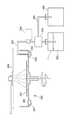
図6に示すレジスト液回収システムの一例は、レジスト塗布装置の一例であるスピンコーター250と、スピンコーター250の回転部の周囲に設けられた回収用パン251で発生する使用済レジスト液252を回収するための回収配管253と、回収配管253中に設けられた回収ポンプ254と、回収配管253の先端に接続された、上記の使用済容器である専用容器1と、回収配管253の途中から分岐する切替バルブ259と、この切替バルブ259から回収配管253と分岐して伸びる配管255と、この配管255の先端に接続される洗浄液回収タンク256とから構成されている。
An example of the resist solution recovery system shown in FIG. 6 recovers a used resist
まず、使用済容器である専用容器1の第2蓋60を取り除いた後に、レジスト液を回収するための回収用チューブ(図示せず)が装着される。回収継手を構成する回収用チューブは、上記の汲み出チューブ40と同様に継手ブラケット30の第2貫通穴33に密着挿入可能な構成となっている。この回収用チューブを介して回収配管253が密閉系で接続される。
First, after removing the
スピンコーター250を運転すると、基板257上の塗布部258よりレジスト液が塗布される。このレジスト液は遠心力により周囲に拡散し、回収用パン251には余剰の使用済レジスト液252が貯留される。ここで、回収ポンプ254を動作させることにより、回収配管253を介して専用容器1に使用済レジスト液252が回収される。すなわち、専用容器1の注出口付き包装袋10内には使用済レジスト液252が再充填されることになる。
When the
なお、上記のように、回収作業開始時の注出口付き包装袋10は、レジスト液供給工程S20で汲み出し工程を経たことによってシュリンクした状態であり、再充填のみでの袋の容量復元が不十分である。このため、このときの充填可能容量(回収可能容量)は、注出口付き包装袋10をあらかじめ窒素や空気で膨らませたレジスト液供給工程S20に比べる少なくなる。しかしながら、レジスト液は実際に塗布された分、回収できる使用済レジスト液の量は少なくなっているので、塗布装置に供給したレジスト量に見合う分の使用済レジスト液を同じ容量の専用容器で十分回収できる。
In addition, as mentioned above, the
なお、切替バルブ259と洗浄液回収タンク256は、シンナーなどで回収配管253を洗浄するためのものであり、所定の洗浄作業が行われる間は洗浄液回収タンク256側に回収液を送る。これにより、専用容器1へのレジスト液以外のコンタミネーションを効果的に防止できる。
The switching
所定量の回収を終えた後、専用容器1から回収用チューブを外し、液出しチューブ40を再度挿入して第2蓋60を取り付けて封止する。これをレジストメーカーなどのレジスト液供給施設100に返送する。これにより、専用容器1は、供給兼回収容器として機能し回収効率の向上に寄与する。なお、上記のレジスト液回収工程S30は、レジスト液供給工程S20と同様にレジスト液塗布装置単位で行われることが好ましい。
After the collection of a predetermined amount, the collection tube is removed from the
<組成確認工程S40>
再充填された専用容器1は、レジスト液供給施設100に返送され、受け入れ段階で組成確認工程S40が行われる。この工程は、複数の異なるレジスト液使用施設200から送られてくる種々のレジストのコンタミネーションを避けるために、専用容器毎にレジストの組成、種類などを確認する工程である。確認方法は特に限定されないが、一例としては、赤外又は近赤外分光法を用いて濃度や種類を測定する方法が挙げられる。
<Composition confirmation process S40>
The refilled
<リサイクル工程S50>
その後、レジスト液供給工程S20と同様の方法により、使用済レジスト液が汲み出され、リサイクル工程S50においてレジスト液はリサイクルされる。リサイクルの方法は従来公知のものが用いることができ特に限定されない。なお、汲み出し終了後の専用容器1からは、注出口付き包装袋10が取り外されて破棄される。外装容器20を洗浄後、新しい注出口付き包装袋10が装着され、レジスト液充填工程S10に使用される。
<Recycling process S50>
Thereafter, the used resist solution is pumped out by the same method as in the resist solution supply step S20, and the resist solution is recycled in the recycling step S50. A conventionally known recycling method can be used and is not particularly limited. In addition, from the
以上説明したように、本発明によれば、従来に比べて大幅にレジスト液の回収を効率化することができ、回収コストを低下してレジスト液のリサイクル率を高めることができる。 As described above, according to the present invention, the recovery of the resist solution can be made more efficient than before, and the recovery cost can be reduced and the recycling rate of the resist solution can be increased.
1 専用容器
10 注出口付き包装袋
11 注出口
12 包装袋本体
20 外装容器
24 開口部
50 第1蓋
60 第2蓋
100 レジスト液供給施設
200 レジスト液使用施設
250 スピンコーター
S10 レジスト液充填工程
S20 レジスト液供給工程
S30 レジスト液回収工程
S40 組成確認工程
S50 リサイクル工程
DESCRIPTION OF
Claims (2)
この専用容器を、前記レジスト液使用施設における使用済レジスト液を回収するためのレジスト液回収容器としても使用し、
前記レジスト液使用施設は、レジスト液塗布装置を備える施設であり、前記レジスト液が充填された内袋から前記レジスト液塗布装置へ前記レジスト液を供給する供給作業と、前記レジスト液塗布装置から実質的に空袋である前記供給作業後の内袋へ前記使用済レジスト液を再充填する回収作業と、を実質的な密封系で行い、
前記回収後に前記レジスト液回収容器を前記レジスト液供給施設に返送し、前記レジスト液供給施設において前記使用済レジスト液を前記内袋から汲み出してリサイクルするレジスト液回収方法。 A double container consisting of an outer container having an opening and an inner bag of the outer container, and using a dedicated container of a predetermined capacity, supplying a resist solution from a resist solution supply facility to a resist solution use facility,
This dedicated container is also used as a resist solution recovery container for recovering the used resist solution in the resist solution use facility ,
The resist solution use facility is a facility provided with a resist solution coating apparatus, and a supply operation for supplying the resist solution from an inner bag filled with the resist solution to the resist solution coating apparatus, and substantially from the resist solution coating apparatus. And a recovery operation for refilling the used resist solution into the inner bag after the supply operation, which is an empty bag, in a substantially sealed system,
A resist solution recovery method in which the resist solution recovery container is returned to the resist solution supply facility after the recovery, and the used resist solution is pumped out of the inner bag and recycled at the resist solution supply facility .
Priority Applications (4)
| Application Number | Priority Date | Filing Date | Title |
|---|---|---|---|
| JP2008016150A JP5249593B2 (en) | 2008-01-28 | 2008-01-28 | Resist solution recovery method |
| TW98102067A TWI413156B (en) | 2008-01-28 | 2009-01-20 | Resist liquid supply and recovery system and method of recovering resist liquid |
| CNA2009100037804A CN101498895A (en) | 2008-01-28 | 2009-01-21 | Photoresist supply recovering system and photoresist recovering method |
| KR20090005848A KR101066055B1 (en) | 2008-01-28 | 2009-01-23 | Resist liquid supply and recovery system and method of recovering resist liquid |
Applications Claiming Priority (1)
| Application Number | Priority Date | Filing Date | Title |
|---|---|---|---|
| JP2008016150A JP5249593B2 (en) | 2008-01-28 | 2008-01-28 | Resist solution recovery method |
Publications (2)
| Publication Number | Publication Date |
|---|---|
| JP2009177056A JP2009177056A (en) | 2009-08-06 |
| JP5249593B2 true JP5249593B2 (en) | 2013-07-31 |
Family
ID=40946013
Family Applications (1)
| Application Number | Title | Priority Date | Filing Date |
|---|---|---|---|
| JP2008016150A Active JP5249593B2 (en) | 2008-01-28 | 2008-01-28 | Resist solution recovery method |
Country Status (2)
| Country | Link |
|---|---|
| JP (1) | JP5249593B2 (en) |
| CN (1) | CN101498895A (en) |
Families Citing this family (5)
| Publication number | Priority date | Publication date | Assignee | Title |
|---|---|---|---|---|
| CN103706525B (en) * | 2013-12-16 | 2015-12-09 | 南通大学 | The sol evenning machine pallet preventing glue from sucking |
| US9421567B2 (en) * | 2014-09-08 | 2016-08-23 | Alpha And Omega Semiconductor Incorporated | Recycle photochemical to reduce cost of material and environmental impact |
| CN105880093A (en) * | 2016-05-31 | 2016-08-24 | 苏州速腾电子科技有限公司 | Sprinkling device for glass caps |
| CN107744678B (en) * | 2017-10-27 | 2021-04-30 | 武汉华星光电技术有限公司 | Cleaning liquid filtering device and method for linear coating machine and linear coating machine |
| CN115121456B (en) * | 2022-07-12 | 2023-06-02 | 广西阳阳铝业有限公司 | Surface treatment process of aluminum alloy part |
Family Cites Families (15)
| Publication number | Priority date | Publication date | Assignee | Title |
|---|---|---|---|---|
| JPS6351638A (en) * | 1986-08-20 | 1988-03-04 | Clean Saafueisu Gijutsu Kk | Resist applying and recovering device in photoetching process |
| JPS63227020A (en) * | 1987-03-17 | 1988-09-21 | Toshiba Corp | Semiconductor device manufacturing equipment |
| JP2509302Y2 (en) * | 1992-05-01 | 1996-09-04 | ニチアス株式会社 | Chemical solution container |
| JPH0592172U (en) * | 1992-05-13 | 1993-12-14 | ニチアス株式会社 | Chemical solution container |
| US5335821A (en) * | 1992-09-11 | 1994-08-09 | Now Technologies, Inc. | Liquid chemical container and dispensing system |
| JPH08203804A (en) * | 1995-01-25 | 1996-08-09 | Hitachi Ltd | Manufacture of flat panel display apparatus |
| JPH0934121A (en) * | 1995-07-20 | 1997-02-07 | Hitachi Ltd | Recycling type resist process |
| JPH09213608A (en) * | 1996-02-01 | 1997-08-15 | Hitachi Ltd | Method and device for coating photoresist |
| JP3751435B2 (en) * | 1998-02-27 | 2006-03-01 | 宮崎沖電気株式会社 | Resist regeneration system and resist regeneration method |
| JP4033600B2 (en) * | 2000-04-28 | 2008-01-16 | 住友化学株式会社 | Resist coating device |
| JP4646381B2 (en) * | 2000-11-13 | 2011-03-09 | 東京エレクトロン株式会社 | Coating liquid supply device and coating device |
| JP4704228B2 (en) * | 2005-09-06 | 2011-06-15 | 東京応化工業株式会社 | Resist solution supply device and remodeling kit for obtaining the resist solution supply device |
| JP2007072138A (en) * | 2005-09-06 | 2007-03-22 | Tokyo Ohka Kogyo Co Ltd | Method for manufacturing resist liquid and resist film using same |
| JP4697882B2 (en) * | 2006-05-19 | 2011-06-08 | 東京エレクトロン株式会社 | Treatment liquid supply apparatus, treatment liquid supply method, and treatment liquid supply control program |
| JP4926563B2 (en) * | 2006-06-28 | 2012-05-09 | 東京応化工業株式会社 | Container for fluid and container containing fluid using the same |
-
2008
- 2008-01-28 JP JP2008016150A patent/JP5249593B2/en active Active
-
2009
- 2009-01-21 CN CNA2009100037804A patent/CN101498895A/en active Pending
Also Published As
| Publication number | Publication date |
|---|---|
| JP2009177056A (en) | 2009-08-06 |
| CN101498895A (en) | 2009-08-05 |
Similar Documents
| Publication | Publication Date | Title |
|---|---|---|
| JP5249593B2 (en) | Resist solution recovery method | |
| US10486956B2 (en) | Apparatus and methods for filling and dispensing liquids | |
| KR101357961B1 (en) | Liquid dispensing systems encompassing gas removal | |
| CN101360663B (en) | Fluid container | |
| EP1821337A4 (en) | Maintenance method, maintenance apparatus, exposure apparatus and device manufacturing method | |
| TW201524886A (en) | Apparatus and method for pressure dispensing of high viscosity liquid-containing materials | |
| JP5297658B2 (en) | Resist liquid supply and recovery system | |
| KR20190135081A (en) | an apparatus for recycling parting agent for die casting | |
| FR3071769A1 (en) | COMPACT INK TANK | |
| TWI413156B (en) | Resist liquid supply and recovery system and method of recovering resist liquid | |
| JP5725266B2 (en) | Chemical container | |
| CN101623956A (en) | Method for refilling ink to ink box and filling tool | |
| JP5436028B2 (en) | Resist solution recovery method | |
| JP5715230B2 (en) | Resist solution recovery method | |
| JPH10194391A (en) | Barrel container device | |
| JP4312335B2 (en) | Weighing device | |
| JP4533914B2 (en) | Portable local washer | |
| JPH11192464A (en) | Auxiliary device for metallic tub cleaner | |
| JP2002126603A (en) | Force-feeding type coating material supply device | |
| JP2001192097A (en) | Liquid feeder | |
| JP2009060129A (en) | Resist coating method | |
| JP2003063598A (en) | Server for repacking sale of liquid cosmetic | |
| JPH10109861A (en) | Leakage oil recovering jig for hydraulic oil elevator |
Legal Events
| Date | Code | Title | Description |
|---|---|---|---|
| A621 | Written request for application examination |
Free format text: JAPANESE INTERMEDIATE CODE: A621 Effective date: 20101021 |
|
| A131 | Notification of reasons for refusal |
Free format text: JAPANESE INTERMEDIATE CODE: A131 Effective date: 20120508 |
|
| A521 | Written amendment |
Free format text: JAPANESE INTERMEDIATE CODE: A523 Effective date: 20120629 |
|
| TRDD | Decision of grant or rejection written | ||
| A01 | Written decision to grant a patent or to grant a registration (utility model) |
Free format text: JAPANESE INTERMEDIATE CODE: A01 Effective date: 20130319 |
|
| A61 | First payment of annual fees (during grant procedure) |
Free format text: JAPANESE INTERMEDIATE CODE: A61 Effective date: 20130412 |
|
| R150 | Certificate of patent or registration of utility model |
Ref document number: 5249593 Country of ref document: JP Free format text: JAPANESE INTERMEDIATE CODE: R150 Free format text: JAPANESE INTERMEDIATE CODE: R150 |
|
| FPAY | Renewal fee payment (event date is renewal date of database) |
Free format text: PAYMENT UNTIL: 20160419 Year of fee payment: 3 |