JP5248552B2 - Video signal processing apparatus and control method thereof - Google Patents
Video signal processing apparatus and control method thereof Download PDFInfo
- Publication number
- JP5248552B2 JP5248552B2 JP2010140970A JP2010140970A JP5248552B2 JP 5248552 B2 JP5248552 B2 JP 5248552B2 JP 2010140970 A JP2010140970 A JP 2010140970A JP 2010140970 A JP2010140970 A JP 2010140970A JP 5248552 B2 JP5248552 B2 JP 5248552B2
- Authority
- JP
- Japan
- Prior art keywords
- demonstration
- image data
- mode
- display
- signal processing
- Prior art date
- Legal status (The legal status is an assumption and is not a legal conclusion. Google has not performed a legal analysis and makes no representation as to the accuracy of the status listed.)
- Expired - Fee Related
Links
Images


Landscapes
- Two-Way Televisions, Distribution Of Moving Picture Or The Like (AREA)
Description
本発明は映像信号処理装置及びその制御方法に関し、例えばデジタルテレビジョン放送受信装置、或いは記録再生装置を店頭に装置を配列した時のデモンストレーション機能について工夫したものである。 The present invention relates to a video signal processing apparatus and a control method therefor, and devise a demonstration function when, for example, a digital television broadcast receiving apparatus or a recording / reproducing apparatus is arranged at a store.
デジタルテレビジョン放送受信装置が店頭に配置されて販売されるとき、デモンストレーション映像を表示するモード(以下デモモードと称する)に切り替ええられることがある。デモモードに切り替えられる装置としては、例えば特許文献1、特許文献2がある。
When a digital television broadcast receiver is placed and sold at a store, it may be switched to a mode for displaying a demonstration video (hereinafter referred to as a demo mode). Examples of devices that can be switched to the demo mode include
特許文献1は、複数のデモモードが選択可能なモード選択画面を表示することができる。モード選択入力がない状態で一定時間が経過すると注意事項の項目データを表示することができる。
特許文献2は、ユーザに対しては、当該ユーザが使用しようとする興味を持った機能に関してデモンストレーションを実行させることができる。また販売店にとっては、状況や要望に応じてデモンストレーションを実行させることができる。 Japanese Patent Application Laid-Open No. 2004-26853 can cause a user to perform a demonstration regarding a function that the user is interested in using. For dealers, demonstrations can be executed according to circumstances and requests.
店頭において、ユーザは、デモンストレーションを実行している興味を持った1つの装置の性能を確認する場合、該興味を持った装置の画面と隣に配列された例えば他社の装置の画面の画面を見比べている。しかし両方が同じ設定機能で動作しているとは限らないので比較に満足できない場合もある。 At the store, when the user confirms the performance of one of the interested devices performing the demonstration, the user compares the screen of the interested device with the screen of the device of another company arranged next to the screen. ing. However, since both are not always operating with the same setting function, the comparison may not be satisfactory.
そこで本実施例では、少なくともデモンストレーション画像出力とオンエアー画像出力を自動的に繰り返すことができ、デモンストレーションのときは外部接続又は内部メモリからの画像ファイルを自動再生し、利用者が装置性能を1つの装置自身で複数画像などの比較検討ができるようにした映像信号処理装置及びその制御方法を提供することを目的とする。 Therefore, in this embodiment, at least the demonstration image output and the on-air image output can be automatically repeated. During the demonstration, the image file from the external connection or the internal memory is automatically reproduced, and the user can control the performance of one device. It is an object of the present invention to provide a video signal processing apparatus and a control method therefor, which are capable of comparatively examining a plurality of images by themselves.
また、実施例では、上記に加えデモンストレーション画像のための画像ファイルを複数用意し、デモンストレーションの複数の画像ファイルを順次再生できるようにし、デモンストレーション実行中において1つの装置で各種の画像内容に対する比較検討ができるようにすることもできる。 In addition, in the embodiment, in addition to the above, a plurality of image files for demonstration images are prepared so that a plurality of demonstration image files can be reproduced in sequence, and a single device can compare and examine various image contents during the demonstration. It can also be made possible.
さらにまたこの実施例では、デデモンストレーション内容がどのような機能をアピールしているものであるかをユーザにわかりやすくすることもできる。 Furthermore, in this embodiment, it is possible to make it easier for the user to understand what function the demonstration contents are appealing.
さらにまた、機能オンオフ時の画面の様子を同一画面で比較しやすいデモンストレーションを得ることもできる。 Furthermore, it is possible to obtain a demonstration that makes it easy to compare the screens when the function is turned on and off on the same screen.
また、外部接続メモリの管理情報からデモンストレーションできる機能を認識して、自動的に上記設定に応じたデモンストレーションを行うこともできる。 It is also possible to recognize a function that can be demonstrated from the management information of the externally connected memory and automatically perform a demonstration according to the above settings.
上記の課題を解決するために、本発明は、機能を説明するためのデモンストレーション用の画像データを格納したメモリと、前記メモリから前記画像データを読み出す画像読み取り部と、読み出した前記画像データを表示用として出力してデモンストレーションモードを実行し、このデモンストレーションモードが終了すると、オンエアー画像データを表示用として出力する表示モードに移行し、この状態で一定時間無操作が経過すると前記デモンストレーションモードに移行し、前記デモンストレーションモードと前記オンエアー画像データの表示モードとを繰り返す表示制御部とを有し、前記表示制御部は、さらに前記デモンストレーションモードのとき、複数の画質調整機能を説明した出力を得る手段と、前記複数の前記画質調整機能による調整が行われた場合の各画面状態を出力する手段を含む。 In order to solve the above problems, the present invention includes a memory storing the image data for the demonstration to explain the functions, and an image reading section for reading the image data from the memory, read the image data Output for display and execute demonstration mode.When this demonstration mode ends, the display mode is switched to output on-air image data for display. A display control unit that repeats the demonstration mode and the display mode of the on-air image data, and the display control unit further obtains an output describing a plurality of image quality adjustment functions in the demonstration mode; wherein the plurality of the image quality adjustment function Comprising means for outputting the screen state when by adjustment has been made.
以下、実施の形態について、図面を参照して説明する。まず放送受信装置について概要を説明する。 Hereinafter, embodiments will be described with reference to the drawings. First, an outline of the broadcast receiving apparatus will be described.
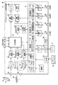
図1は、上記デジタルテレビジョン放送受信装置41の主要な信号処理系を示している。すなわち、BS/CSデジタル放送受信用のアンテナ43で受信した衛星デジタルテレビジョン放送信号は、入力端子44を介して衛星デジタル放送用のチューナ45に供給されることにより、所望のチャンネルの放送信号が選局される。
FIG. 1 shows a main signal processing system of the digital
チューナ45で選局された放送信号は、PSK(Phase Shift Keying)復調器46に供給されて、デジタルの映像信号及び音声信号に復調された後、信号処理部47に出力される。
The broadcast signal selected by the
また、地上デジタル放送受信用のアンテナ48で受信した地上デジタルテレビジョン放送信号は、入力端子49を介して地上デジタル放送用のチューナ50に供給されることにより、所望のチャンネルの放送信号が選局される。
The terrestrial digital television broadcast signal received by the terrestrial digital
チューナ50で選局された放送信号は、OFDM(Orthogonal Frequency Division Multiplexing)復調器51に供給されて、デジタルの映像信号及び音声信号に復調された後、信号処理部47に出力される。
The broadcast signal selected by the
また地上波アナログ信号を受信するアナログチューナ58も設けられている。アナログチューナ58で受信された信号は、アナログ復調器59で復調され信号処理部47に出力される。
An
ここで信号処理部47は、PSK復調器46から供給されたデジタルの映像信号及び音声信号と、OFDM復調器51から供給されたデジタルの映像信号及び音声信号と、アナログ復調器59から供給された映像信号及び音声信号と、さらにライン入力端子からの映像信号及び音声信号とに対して、選択的に所定のデジタル信号処理を施し、グラフィック処理部52及び音声処理部53に出力している。
Here, the
このうち、グラフィック処理部52は、信号処理部47から供給されるデジタルの映像信号に、OSD(On Screen Display)信号生成部54で生成されるOSD信号を重畳して出力する機能を有する。また、このグラフィック処理部52は、信号処理部47の出力映像信号と、OSD信号生成部54の出力OSD信号とを選択的に出力すること、また、両出力を多重したり、画面の半分を構成するように組み合わせて出力することができる。
Among these, the
グラフィック処理部52から出力されたデジタルの映像信号は、映像処理部55に供給される。この映像処理部55は、入力されたデジタルの映像信号を、映像表示部57で表示可能なフォーマットのアナログ映像信号に変換し、映像表示部57に出力して映像表示させる。
The digital video signal output from the
上記音声処理部53は、入力されたデジタルの音声信号を、スピーカ56で再生可能なフォーマットのアナログ音声信号に変換し、スピーカ56に出力して音声再生させる。
The
ここで、このデジタルテレビジョン放送受信装置11は、上記した各種の受信動作を含むその全ての動作を制御部61によって統括的に制御されている。
Here, in the digital television
制御部61は、CPU(Central Processing Unit)等を内蔵している。操作部71からの操作情報を受けたとき、または、リモートコントローラ72から送出された操作情報を受光部73から受信したとき、制御部61は、その操作内容が装置に反映されるように各部を統括して制御している。
The
この場合、制御部61は、主として、そのCPUが実行する制御プログラムを格納したROM(Read Only Memory)611と、該CPUに作業エリアを提供するRAM(Random Access Memory)612と、各種の設定情報及び制御情報等が格納される不揮発性メモリ613とを利用している。
In this case, the
制御部61は、カードI/F(Interface)75を介して、第1のメモリカード77が装着可能なカードホルダ76に接続されている。これによって、制御部61は、カードホルダ76に装着された第1のメモリカード77と、カードI/F75を介して情報の送受信を行なうことができる。
The
制御部61は、図示していないが、さらに別のカードI/Fを介して、第2のメモリカードが装着可能なカードホルダに接続されてもよい。
Although not shown, the
制御部61は明るさセンサー78に接続されている。これにより周囲の明るさ情報を取得し、例えば画面の明るさを自動制御することが可能である。
The
制御部61は、通信I/F81を介して第1のLAN端子82に接続されている。これにより、制御部61は、第1のLAN端子82に接続されたLAN対応のHDD(ハードディスクドライブ装置)と、通信I/F81を介して情報の送受信を行なうことができる。この場合、制御部61は、DHCP(Dynamic Host Configuration Protocol)サーバ機能を有し、第1のLAN端子82に接続されたLAN対応のHDDにIP(Internet Protocol)アドレスを割り当てて制御している。制御部61は、図示していないがさらに別の通信I/Fを介して第2のLAN端子に接続されてもよい。
The
制御部61は、USB I/F83を介してUSB端子84に接続されている。これにより、制御部61は、USB端子84に接続された各機器と、USB I/F83を介して情報の送受信を行なうことができる。
The
上記制御部61は、i.Link(登録商標) I/F85を介してi.Link(登録商標)端子86に接続されている。これにより、制御部61は、i.Link(登録商標)端子86に接続された各機器と、i.Link(登録商標)I/F85を介して情報の送受信を行なうことができる。
The
上記制御部61は、HDMI(High Definition Multimedia Interface)規格に合致したHDMI I/F 87を介してHDMI端子88に接続された各機器と情報の送受信を行なうことができる。
The
ところで、上記したメモリカード77には、例えば店頭デモンストレーション用のカードがある。店頭デモンストレーションを行う装置には、店頭デモンストレーションカードを装着することができる。これに伴い、制御部61は、設定部621、デモンストレーション実行部622、読み取り部623、表示制御部624を有する。
Incidentally, the
設定部621は、操作に応じてデモンストレーションの実行内容を設定する設定信号を出力する。デモンストレーション実行部622は、設定信号に応じてデモンストレーション動作シーケンスを実行する。読み取り部623は、デモンストレーション実行に伴いメモリからデモンストレーション画像データを読み出す。表示制御部624は、読み出したデモンストレーション画像データの画像を表示部に出力しデモンストレーションモードが終わるとオンエアー画像データの画像を表示部に出力し、一定時間無操作が経過するとデモンストレーションモードに移行する。
The setting unit 621 outputs a setting signal for setting the execution contents of the demonstration according to the operation. The demonstration execution unit 622 executes a demonstration operation sequence according to the setting signal. The reading unit 623 reads the demonstration image data from the memory along with the execution of the demonstration. The
また管理情報判定部625、操作入力処理部626も制御部61には含まれる。管理情報判定部625はメモリから読み出したデモンストレーションに関する管理情報を解析し、自己の規格に適応するデモンストレーション用ファイルが存在するか否かを判定している。操作入力処理部626は、リモートコントローラ72からの操作入力を判定し、装置の機能を設定するための処理部である。なおデモンストレーション用情報(デモンストレーション画像データ、デモンストレーション管理情報など)は、装置内部の内蔵メモリに格納されていてもよい。
Also included in the
図2は、上記リモートコントローラ72の外観を示している。このリモートコントローラ72には、主として、電源キー17a、入力切換キー17b、衛星デジタル放送チャンネルのダイレクト選局キー17c、地上波放送チャンネルのダイレクト選局キー17d、クイックキー17e、カーソルキー17f、決定キー17g、番組表キー17h、ページ切換キー17i、faceネット(ナビゲーション)キー17j、戻るキー17k、終了キー17l、青,赤,緑のカラーキー17mb、17mr、17mg、チャンネルアップダウンキー17n、音量調整キー17o等が設けられている。
FIG. 2 shows the external appearance of the
番組表キー17hを押すと、番組表が表示される。終了キー171を押すと、オンエアー(現在受信中のチャンネルの映像の表示)状態に戻る。
When the program guide key 17h is pressed, the program guide is displayed. When the
図3は上記したデジタルテレビジョン放送受信装置の特徴的な動作を説明する図である。この装置によると、メモリカード77として店頭デモンストレーション用のカードを使用し、装置をオンし、リモートコントローラ72の例えばデモキー17pを押すと、デモンストレーション動作に移行することができる。デモンストレーション動作では、例えば予め設定されている画像ファイルの画像データが再生される。また装置の機能などについてインストラクションが実行されてもよい。デモンストレーション内容については各種の実施例が可能である。
FIG. 3 is a diagram for explaining the characteristic operation of the digital television broadcast receiver described above. According to this apparatus, when a store demonstration card is used as the
この発明の装置では、リモートコントローラ72の例えばデモキー17pを押すと、設定部621がデモンストレーションを実行する設定信号を出力する。すると、読み取り部623が前記設定信号に応答し前記メモリからデモンストレーション画像データを読み出す。そして、表示制御部624が読み出したデモンストレーション画像データの画像を表示部に出力する。
In the apparatus of the present invention, when the demo key 17p of the
ここで表示制御部624は、読み出したデモンストレーション画像データを表示部57に出力するデモンストレーションモードを実行し、このデモンストレーションモードが終了すると、オンエアー画像データを表示部57に出力する表示モードに移行し、この状態で一定時間無操作が経過すると前記デモンストレーションモードに移行する。この基本動作が図3に示されている。
Here, the
このような動作を行った場合、デモンストレーションのときは外部接続又は内部メモリからの画像ファイルを自動再生し、またオンエアー画像を視聴できる。よって利用者は装置性能を1つの装置自身で複数画像の比較検討ができ、かつデモンストレーションで説明された画像内容をオンエアー画面で確認できる。 When such an operation is performed, an image file from an external connection or an internal memory can be automatically reproduced and an on-air image can be viewed during a demonstration. Therefore, the user can compare and examine a plurality of images with one device itself, and can confirm the image contents explained in the demonstration on the on-air screen.
なおオンエアー動作状態において、一定時間操作がなされないとデモンストレーション動作に移行することを記載しているが、この一定時間は任意に変更が可能である。この変更は例えばメニュー画面に「オンエアーからデモンストレーションへの移行時間XX分」という項目を設けて、この項目で時間設定できるようにしてもよい。 In the on-air operation state, it is described that the operation shifts to the demonstration operation when no operation is performed for a certain period of time, but this certain period of time can be arbitrarily changed. For this change, for example, an item “transition time XX minutes from on-air to demonstration” may be provided on the menu screen so that the time can be set by this item.
デモンストレーションの種類を選択するときは、例えば、デモンストレーションメニューから、デモンストレーションの機能の項目が選択される。例えば機能項目としては、映像高精細化機能、動画改善機能、高音質機能、自動映像調整機能、メディアプレーヤー、CMなどがある。 When selecting the type of demonstration, for example, a demonstration function item is selected from the demonstration menu. For example, the function items include a video enhancement function, a moving picture improvement function, a high sound quality function, an automatic video adjustment function, a media player, and a CM.
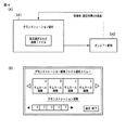
この発明は上記の実施形態に限るものではない。図4(A)に示すように、デモンストレーション画像のための画像ファイルを複数用意し、デモンストレーション動作においては、アピールしたいデモンストレーションの再生画像を選択できるように構成してもよい。図4(B)は、メモリカード77に格納されている複数のデモンストレーション画像ファイルから、デモンストレーションに使用する画像を選択する際の表示部57における選択画面の様子を示している。例えばメニュー画面から「デモ画像設定」のアイテムを選択し、決定ボタンを押すと、図4(B)に示すような画面が現れる。上側にはデモンストレーション画像のための複数の画像ファイルの代表画像がサムネール配列される。ここで、ユーザは、デモンストレーションに使用する希望のファイルのサムネール画像をカーソルで選択し、決定ボタンを押す。すると、画面の下側にあるように、選択した順に画像のファイル名A,C,D・・・・が配列される。この場合、選択するファイルは1個でもよい。
The present invention is not limited to the above embodiment. As shown in FIG. 4 (A), a plurality of image files for demonstration images may be prepared, and in the demonstration operation, it may be configured such that a reproduction image of a demonstration to be appealed can be selected. FIG. 4B shows a selection screen on the
この設定の後、戻るボタンを操作し、デモキー17pを押すとデモンストレーション動作に移行する。 After this setting, if the return button is operated and the demo key 17p is pressed, the operation proceeds to the demonstration operation.
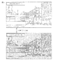
図5のデモンストレーション動作例は、映像高精細化機能デモンストレーションが選択された例である。このデモンストレーションは映像高精細化機能についてのデモンストレーションである。デモンストレーション動作を開始すると、映像高精細化機能に関するインストラクションが例えば5秒程度あり、実際にデモンストレーション画像(動画でも静画でもよい)が24秒間実演される。このデモンストレーションでは、例えば、映像高精細化機能の入/切を2秒毎に切替えするもので、1種類約8秒間の映像出力を行う。これにより利用者は、映像高精細化機能の効果を比較検討してみることができる。 The demonstration operation example in FIG. 5 is an example in which the video enhancement function demonstration is selected. This demonstration is a demonstration of the video enhancement function. When the demonstration operation is started, there are about 5 seconds of instructions regarding the video enhancement function, and a demonstration image (which may be a moving image or a still image) is actually demonstrated for 24 seconds. In this demonstration, for example, the on / off switching of the video enhancement function is switched every 2 seconds, and one type of video output is performed for about 8 seconds. As a result, the user can compare and examine the effect of the video enhancement function.
図6のデモンストレーション動作例は、動画改善機能デモンストレーションが選択された例である。このデモンストレーションは、動画改善機能に関するものである。デモンストレーション動作を開始すると、例えば動画改善機能についてのインストラクションが5秒程度あり、実際の動画改善機能が実行される(約16秒程度)。このときは、例えば動画改善機能の全画面オン→全画面オフ→全画面オン・・・が2秒毎に繰り替えされる。これにより、利用者は、アクティブビジョンM200の効果を認識できることになる。 The demonstration operation example in FIG. 6 is an example in which the moving image improvement function demonstration is selected. This demonstration is about the video improvement function. When the demonstration operation is started, for example, there is an instruction about the moving image improvement function for about 5 seconds, and the actual moving image improvement function is executed (about 16 seconds). At this time, for example, full screen on → full screen off → full screen on... Of the moving image improvement function is repeated every 2 seconds. As a result, the user can recognize the effect of the active vision M200.
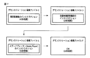
図7に示すデモンストレーション動作は、複数の画像ファイルが順次再生できるように設定した場合である。この例は、デモンストレーション画像ファイルC,D,E,Fが順次再生されるように選択設定された例である。デモンストレーション画像ファイルCは、装置機能である高音質機能のインストラクションが45秒程度、動画とともに実行されるファイルである。デモンストレーション画像ファイルDは、装置機能である自動映像調整機能のインストラクションが30秒程度、例えば各種静画とともに実行されるファイルである。デモンストレーション画像ファイルEは、装置機能であるメディアプレーヤーのインストラクションが30秒程度、例えば動画とともに実行されるファイルである。デモンストレーション画像ファイルFは、コマーシャル映像であり30秒程度、動画とともに実行されるファイルである。 The demonstration operation shown in FIG. 7 is a case where setting is made so that a plurality of image files can be sequentially reproduced. In this example, the demonstration image files C, D, E, and F are selected and set so as to be sequentially reproduced. The demonstration image file C is a file in which an instruction of a high sound quality function as a device function is executed with a moving image for about 45 seconds. The demonstration image file D is a file in which an instruction of an automatic video adjustment function as an apparatus function is executed for about 30 seconds, for example, together with various still images. The demonstration image file E is a file in which a media player instruction as a device function is executed for about 30 seconds, for example, together with a moving image. The demonstration image file F is a commercial video and is a file that is executed with a video for about 30 seconds.
図8は、デモンストレーション動作において、多数の動画ファイルが順次再生される様子を示している。最後の画像ファイルが再生されると、基本的にはオンエアー動作に移行する。そして、オンエアー動作において、2分間何の操作もない場合、デモンストレーション動作に移行する。 FIG. 8 shows a state in which a large number of moving image files are sequentially reproduced in the demonstration operation. When the last image file is played, the operation basically shifts to an on-air operation. Then, in the on-air operation, when there is no operation for 2 minutes, the operation proceeds to the demonstration operation.
図9は、実際の動画改善あるいは高画質改善機能が実行された(約16秒程度)とき、例えば動画改善或いは高画質改善の全画面オン→全画面オフ→全画面オン・・・が2秒毎(必ずしも2秒とは限らない)に繰り替えされた様子を示している。これにより、利用者は、画面の明るさの変化を視覚し、アクティブビジョンM100の効果を認識できることになる。 FIG. 9 shows that when the actual moving image improvement or high image quality improvement function is executed (about 16 seconds), for example, the full screen on → full screen off → full screen on... It shows a state of being repeated every time (not necessarily 2 seconds). As a result, the user can visually recognize the change in the brightness of the screen and recognize the effect of the active vision M100.
この発明は上記の実施形態に限定されるものではない。例えば店頭デモンストレーション用のメモリが、図10に示すような管理情報テーブルを格納していてもよい。 The present invention is not limited to the above embodiment. For example, a store demonstration memory may store a management information table as shown in FIG.
即ち、管理情報テーブルは複数のデモンストレーションの種類名と、複数の機種名と、各機種が各デモンストレーションを実行できるか否かを識別した実行可否情報とを含む。管理情報テーブルを参照して、設定部612はデモンストレーションを実行する設定信号を確定している。
That is, the management information table includes a plurality of demonstration type names, a plurality of model names, and executable information identifying whether each model can execute each demonstration. With reference to the management information table, the
デモンストレーションの種類としては、解像度に関するデモンストレーション、先に説明したアクティブビジョンM200(クリアスキャン240と呼ばれる場合もある),アクティブビジョンM100(クリアフレームと呼ばれる場合もある)に関するデモンストレーションがある。さらにまた、ドルビーボリウム、オートビュー、メディアプレーヤー、CMに関するデモンストレーションがある。それぞれのデモンストレーションデータの格納ファイルにはファイル名が設定されている。 As the types of demonstration, there are a demonstration regarding resolution, a demonstration regarding active vision M200 (also referred to as clear scan 240), and a demonstration regarding active vision M100 (also referred to as clear frame) described above. There are also demonstrations of Dolby Volume, Autoview, Media Player, and CM. A file name is set for each demonstration data storage file.
次に、各種デジタルテレビジョン放送受信装置がどのデモンストレーションに対して、対応できるのかを示すフラッグが記述されている。各種デジタルテレビジョン放送受信装置は型名で分類されており、機種A、機種B、機種C、機種D、機種Eが例として挙げられている。 Next, a flag indicating which demonstration the various digital television broadcast receiving apparatuses can handle is described. Various digital television broadcast receiving apparatuses are classified by model name, and model A, model B, model C, model D, and model E are given as examples.
機種A,機種Bは、いずれのデモンストレーション機能を備えていないことを示している。機種Eは、いずれのデモンストレーション機能をも備えていることを示している。映像高精細機能、動画改善機能、高音質機能、自動映像調整機能、メディアプレーヤー、CMに関するデモンストレーション機能である。また機種Dは、動画改善機能に関するデモンストレーション機能を備えていないことを示している。また機種Cは、動画改善機能、高音質機能、自動映像調整機能に関するデモンストレーション機能を備えていないことを示している。 Model A and model B indicate that none of the demonstration functions are provided. Model E shows that it has any demonstration function. These are demonstration functions related to high-definition video functions, video improvement functions, high-quality sound functions, automatic video adjustment functions, media players, and commercials. Model D indicates that it does not have a demonstration function related to the video improvement function. Model C indicates that it does not have a demonstration function for moving picture improvement, high sound quality, and automatic video adjustment.
上記のようにデモンストレーション用のメモリに管理情報が格納されていた場合、メモリのデータは統一したデータを作成して格納することができる。つまりメモリのデータを機種別に作成する必要がない。 When the management information is stored in the demonstration memory as described above, unified data can be created and stored in the memory data. In other words, there is no need to create memory data for each model.
一方、デジタルテレビジョン放送受信装置としては、上記管理情報を読み取り解析し、対応可能なデモンストレーション用ファイルのファイル名を認識し、当該ファイルを指定することで、ファイルを読出しRAM上に展開し、デモンストレーションを実行することができる。 On the other hand, as a digital television broadcast receiving apparatus, the management information is read and analyzed, the file name of a compatible demonstration file is recognized, and the file is read out on the RAM by designating the file, and the demonstration is performed. Can be executed.
上記したように本実施形態は映像信号処理装置及びデジタルテレビジョン放送受信装置に適用されるものである。また実施形態は、記録再生装置、セットトップボックスなどにも適用されて有用である。 As described above, this embodiment is applied to a video signal processing apparatus and a digital television broadcast receiving apparatus. The embodiment is also useful when applied to a recording / reproducing apparatus, a set top box, or the like.
45・・・衛星デジタル放送用のチューナ、46・・・PSK復調器、47・・・信号処理部、48・・・地上デジタル放送受信用のアンテナ、51・・・OFDM復調器、52・・・グラフィック処理部、53・・・音声処理部、54・・・OSD信号生成部、55・・・映像処理部、56・・・スピーカ、57・・・映像表示部、61・・・制御部、621・・・設定部、622・・・デモンストレーション実行部、623・・・読み取り部、624・・・表示制御部、625・・・管理情報判定部、626・・・操作入力処理部、72・・・リモートコントローラ。
45 ... tuner for satellite digital broadcasting, 46 ... PSK demodulator, 47 ... signal processing unit, 48 ... antenna for receiving terrestrial digital broadcasting, 51 ... OFDM demodulator, 52. Graphic processing unit, 53 ... audio processing unit, 54 ... OSD signal generation unit, 55 ... video processing unit, 56 ... speaker, 57 ... video display unit, 61 ... control unit 621... Setting unit 622 Demonstration execution unit 623
Claims (5)
前記メモリから前記画像データを読み出す画像読み取り部と、
読み出した前記画像データを表示用として出力してデモンストレーションモードを実行し、このデモンストレーションモードが終了すると、オンエアー画像データを表示用として出力する表示モードに移行し、この状態で一定時間無操作が経過すると前記デモンストレーションモードに移行し、前記デモンストレーションモードと前記オンエアー画像データの表示モードとを繰り返す表示制御部とを有し、
前記表示制御部は、さらに前記デモンストレーションモードのとき、複数の画質調整機能を説明した出力を得る手段と、
前記複数の前記画質調整機能による調整が行われた場合の各画面状態を出力する手段を含むことを特徴とする映像信号処理装置。 A memory for storing image data for demonstration to illustrate the function,
An image reading unit for reading the image data from the memory;
The read-out image data is output for display and a demonstration mode is executed. When this demonstration mode is completed, the display mode is shifted to a display mode for outputting on-air image data for display. Transition to the demonstration mode , having a display control unit that repeats the demonstration mode and the display mode of the on-air image data ,
The display control unit further obtains an output describing a plurality of image quality adjustment functions when in the demonstration mode;
A video signal processing apparatus comprising: means for outputting each screen state when adjustment is performed by the plurality of image quality adjustment functions.
前記受信部からの受信信号を復調及び信号処理し映像データに変換する復調及び信号処理部と、
前記復調及び信号処理部からの映像データ及び画像読み取り部からのデモンストレーション画像データが供給される映像表示部と、
前記メモリを着脱可能なホルダと、を有したことを特徴とする請求項1記載の映像信号処理装置。 Furthermore, a receiving unit for receiving a television broadcast signal;
A demodulation and signal processing unit that demodulates and processes the received signal from the receiving unit and converts the received signal into video data;
A video display unit to which video data from the demodulation and signal processing unit and demonstration image data from the image reading unit are supplied;
The video signal processing apparatus according to claim 1, further comprising a holder to which the memory can be attached and detached.
前記メモリから前記画像データを読み出し、
読み出した前記画像データを表示用として出力してデモンストレーションモードを実行し、このデモンストレーションモードが終了すると、オンエアー画像データを表示用として出力する表示モードに移行し、この状態で一定時間無操作が経過すると前記デモンストレーションモードに移行し、前記デモンストレーションモードと前記オンエアー画像データの表示モードとを繰り返し、
さらに前記デモンストレーションモードのとき、複数の画質調整機能を説明した出力を得るようにし、
前記複数の前記画質調整機能による調整が行われた場合の各画面状態を得ることができることを特徴とする映像信号処理装置の制御方法。 The demonstration image data for demonstration to explain the functions from a memory which stores read the image data, a control method of a video signal processing apparatus for executing a demonstration,
Reading the image data from the memory;
The read-out image data is output for display and a demonstration mode is executed. When this demonstration mode is completed, the display mode is shifted to a display mode for outputting on-air image data for display. Transition to the demonstration mode, repeat the demonstration mode and the display mode of the on-air image data,
Furthermore, in the demonstration mode, an output describing a plurality of image quality adjustment functions is obtained.
A method of controlling a video signal processing apparatus, characterized in that each screen state can be obtained when adjustment by the plurality of image quality adjustment functions is performed.
Priority Applications (1)
| Application Number | Priority Date | Filing Date | Title |
|---|---|---|---|
| JP2010140970A JP5248552B2 (en) | 2010-06-21 | 2010-06-21 | Video signal processing apparatus and control method thereof |
Applications Claiming Priority (1)
| Application Number | Priority Date | Filing Date | Title |
|---|---|---|---|
| JP2010140970A JP5248552B2 (en) | 2010-06-21 | 2010-06-21 | Video signal processing apparatus and control method thereof |
Related Parent Applications (1)
| Application Number | Title | Priority Date | Filing Date |
|---|---|---|---|
| JP2009049369A Division JP4543114B1 (en) | 2009-03-03 | 2009-03-03 | Video signal processing apparatus and control method thereof |
Publications (2)
| Publication Number | Publication Date |
|---|---|
| JP2010206845A JP2010206845A (en) | 2010-09-16 |
| JP5248552B2 true JP5248552B2 (en) | 2013-07-31 |
Family
ID=42967778
Family Applications (1)
| Application Number | Title | Priority Date | Filing Date |
|---|---|---|---|
| JP2010140970A Expired - Fee Related JP5248552B2 (en) | 2010-06-21 | 2010-06-21 | Video signal processing apparatus and control method thereof |
Country Status (1)
| Country | Link |
|---|---|
| JP (1) | JP5248552B2 (en) |
Families Citing this family (2)
| Publication number | Priority date | Publication date | Assignee | Title |
|---|---|---|---|---|
| JP2015220514A (en) * | 2014-05-15 | 2015-12-07 | 三菱電機株式会社 | Video display device and recording medium |
| CN116489469B (en) * | 2023-03-31 | 2025-08-05 | 海信视像科技股份有限公司 | Display device and image quality demonstration method |
Family Cites Families (11)
| Publication number | Priority date | Publication date | Assignee | Title |
|---|---|---|---|---|
| JPH0451682A (en) * | 1990-06-19 | 1992-02-20 | Sanyo Electric Co Ltd | Automatic specification displaying method for television receiver |
| JPH0863320A (en) * | 1994-08-25 | 1996-03-08 | Matsushita Electric Ind Co Ltd | Display with operation menu |
| JPH10224709A (en) * | 1997-02-04 | 1998-08-21 | Toshiba Corp | Display control device and television receiver |
| JP2001236155A (en) * | 2000-02-24 | 2001-08-31 | Hitachi Ltd | Guidance system |
| JP2001268475A (en) * | 2000-03-15 | 2001-09-28 | Sony Corp | Image quality adjustment method and image quality adjustment device |
| JP2005094299A (en) * | 2003-09-17 | 2005-04-07 | Dainippon Printing Co Ltd | TV screensaver |
| JP2007060335A (en) * | 2005-08-25 | 2007-03-08 | Sanyo Electric Co Ltd | Content reproducing apparatus |
| JP2007081600A (en) * | 2005-09-13 | 2007-03-29 | Sony Corp | Function demonstration method of video display system and remote controller |
| JP2007150787A (en) * | 2005-11-29 | 2007-06-14 | Pioneer Electronic Corp | Playback content switching system for video / audio equipment |
| JP4153980B2 (en) * | 2006-08-30 | 2008-09-24 | 松下電器産業株式会社 | Electronic equipment with operation guide providing function |
| JP2008092418A (en) * | 2006-10-04 | 2008-04-17 | Sharp Corp | Television operating system and television receiver |
-
2010
- 2010-06-21 JP JP2010140970A patent/JP5248552B2/en not_active Expired - Fee Related
Also Published As
| Publication number | Publication date |
|---|---|
| JP2010206845A (en) | 2010-09-16 |
Similar Documents
| Publication | Publication Date | Title |
|---|---|---|
| JP4828812B2 (en) | Television broadcast receiver | |
| JP4331249B2 (en) | Video display device | |
| JP5150158B2 (en) | Television receiver and television display method | |
| JP5618633B2 (en) | Program guide creation device, program guide creation method, and program | |
| JP4543114B1 (en) | Video signal processing apparatus and control method thereof | |
| JP5248552B2 (en) | Video signal processing apparatus and control method thereof | |
| JP2008033138A (en) | Video signal processing apparatus and video signal processing method | |
| JP2006080664A (en) | Signal reproducing apparatus and signal reproducing method | |
| JP2006094409A (en) | Program guide display device and program guide display method | |
| JP2006246249A (en) | Video signal processing apparatus and video signal processing method | |
| CN101035216B (en) | television broadcast receiver | |
| CN103067684A (en) | Video reproduction apparatus and video reproduction method | |
| KR100522956B1 (en) | Apparatus and methdo capable of processing data | |
| JP2007074158A (en) | REPRODUCTION SYSTEM AND REPRODUCTION METHOD USING THE SYSTEM | |
| JP2006246247A (en) | Video signal processing apparatus and video signal processing method | |
| JP2009200727A (en) | Sound switching apparatus, sound switching method and broadcast receiver | |
| JP5185467B1 (en) | Video playback apparatus and video playback method | |
| JP4624806B2 (en) | Recording / playback device with program title display | |
| JP2007036948A (en) | Broadcast receiving apparatus and connected device control method | |
| JP2013090211A (en) | Video reproducing device and video reproducing method | |
| JP2006080695A (en) | Video playback apparatus and video playback method | |
| JP2006129242A (en) | Electronic program guide output device, electronic program guide display device, and electronic program guide display method | |
| JP2006174344A (en) | Video signal output device and video signal output method | |
| JP2015015740A (en) | Program guide creation apparatus, program guide creation method, and program | |
| JP2011217188A (en) | Broadcast-receiving apparatus and display control method |
Legal Events
| Date | Code | Title | Description |
|---|---|---|---|
| A621 | Written request for application examination |
Free format text: JAPANESE INTERMEDIATE CODE: A621 Effective date: 20100621 |
|
| A131 | Notification of reasons for refusal |
Free format text: JAPANESE INTERMEDIATE CODE: A131 Effective date: 20120828 |
|
| A521 | Written amendment |
Free format text: JAPANESE INTERMEDIATE CODE: A523 Effective date: 20121029 |
|
| TRDD | Decision of grant or rejection written | ||
| A01 | Written decision to grant a patent or to grant a registration (utility model) |
Free format text: JAPANESE INTERMEDIATE CODE: A01 Effective date: 20130319 |
|
| A61 | First payment of annual fees (during grant procedure) |
Free format text: JAPANESE INTERMEDIATE CODE: A61 Effective date: 20130410 |
|
| FPAY | Renewal fee payment (event date is renewal date of database) |
Free format text: PAYMENT UNTIL: 20160419 Year of fee payment: 3 |
|
| LAPS | Cancellation because of no payment of annual fees |