JP5247722B2 - Integrated soft central floor console - Google Patents
Integrated soft central floor console Download PDFInfo
- Publication number
- JP5247722B2 JP5247722B2 JP2009544969A JP2009544969A JP5247722B2 JP 5247722 B2 JP5247722 B2 JP 5247722B2 JP 2009544969 A JP2009544969 A JP 2009544969A JP 2009544969 A JP2009544969 A JP 2009544969A JP 5247722 B2 JP5247722 B2 JP 5247722B2
- Authority
- JP
- Japan
- Prior art keywords
- panel
- central console
- outer cover
- attached
- side panel
- Prior art date
- Legal status (The legal status is an assumption and is not a legal conclusion. Google has not performed a legal analysis and makes no representation as to the accuracy of the status listed.)
- Expired - Fee Related
Links
Images


Classifications
-
- B—PERFORMING OPERATIONS; TRANSPORTING
- B60—VEHICLES IN GENERAL
- B60R—VEHICLES, VEHICLE FITTINGS, OR VEHICLE PARTS, NOT OTHERWISE PROVIDED FOR
- B60R7/00—Stowing or holding appliances inside vehicle primarily intended for personal property smaller than suit-cases, e.g. travelling articles, or maps
- B60R7/04—Stowing or holding appliances inside vehicle primarily intended for personal property smaller than suit-cases, e.g. travelling articles, or maps in driver or passenger space, e.g. using racks
-
- B—PERFORMING OPERATIONS; TRANSPORTING
- B60—VEHICLES IN GENERAL
- B60N—SEATS SPECIALLY ADAPTED FOR VEHICLES; VEHICLE PASSENGER ACCOMMODATION NOT OTHERWISE PROVIDED FOR
- B60N2/00—Seats specially adapted for vehicles; Arrangement or mounting of seats in vehicles
- B60N2/75—Arm-rests
- B60N2/79—Adaptations for additional use of the arm-rests
- B60N2/793—Adaptations for additional use of the arm-rests for use as storage compartments
-
- B—PERFORMING OPERATIONS; TRANSPORTING
- B60—VEHICLES IN GENERAL
- B60N—SEATS SPECIALLY ADAPTED FOR VEHICLES; VEHICLE PASSENGER ACCOMMODATION NOT OTHERWISE PROVIDED FOR
- B60N3/00—Arrangements or adaptations of other passenger fittings, not otherwise provided for
- B60N3/10—Arrangements or adaptations of other passenger fittings, not otherwise provided for of receptacles for food or beverages, e.g. refrigerated
- B60N3/101—Arrangements or adaptations of other passenger fittings, not otherwise provided for of receptacles for food or beverages, e.g. refrigerated fixed
-
- B—PERFORMING OPERATIONS; TRANSPORTING
- B60—VEHICLES IN GENERAL
- B60R—VEHICLES, VEHICLE FITTINGS, OR VEHICLE PARTS, NOT OTHERWISE PROVIDED FOR
- B60R11/00—Arrangements for holding or mounting articles, not otherwise provided for
- B60R2011/0001—Arrangements for holding or mounting articles, not otherwise provided for characterised by position
- B60R2011/0003—Arrangements for holding or mounting articles, not otherwise provided for characterised by position inside the vehicle
- B60R2011/0007—Mid-console
-
- Y—GENERAL TAGGING OF NEW TECHNOLOGICAL DEVELOPMENTS; GENERAL TAGGING OF CROSS-SECTIONAL TECHNOLOGIES SPANNING OVER SEVERAL SECTIONS OF THE IPC; TECHNICAL SUBJECTS COVERED BY FORMER USPC CROSS-REFERENCE ART COLLECTIONS [XRACs] AND DIGESTS
- Y10—TECHNICAL SUBJECTS COVERED BY FORMER USPC
- Y10T—TECHNICAL SUBJECTS COVERED BY FORMER US CLASSIFICATION
- Y10T29/00—Metal working
- Y10T29/48—Upholstered article making
- Y10T29/481—Method
Landscapes
- Engineering & Computer Science (AREA)
- Mechanical Engineering (AREA)
- Transportation (AREA)
- Physics & Mathematics (AREA)
- Thermal Sciences (AREA)
- Aviation & Aerospace Engineering (AREA)
- Vehicle Step Arrangements And Article Storage (AREA)
- Passenger Equipment (AREA)
- Body Structure For Vehicles (AREA)
Abstract
Description
本開示の主題は、一般に車両構成部品及びこのような構成部品の製造方法の分野に関連する。より詳細には、本開示の主題は、様々な大きさの人物に適応するように構成される収納コンパートメント及びパッド入りアームレストに関する。本開示の主題はさらに、中央コンソールを製造する方法に関する。 The subject matter of the present disclosure relates generally to the field of vehicle components and methods for manufacturing such components. More particularly, the subject matter of the present disclosure relates to storage compartments and padded armrests that are configured to accommodate various sized persons. The subject matter of the present disclosure further relates to a method of manufacturing a central console.
(関連出願への相互参照)
本願は、2007年1月4日に提出された合衆国仮出願第60878618号への優先権を主張し、参照によりその開示の全体が本明細書に組み込まれる。
(Cross-reference to related applications)
This application claims priority to US Provisional Application No. 60878618, filed Jan. 4, 2007, the entire disclosure of which is incorporated herein by reference.
(背景)
例えば自動車、トラック、航空機、ボート等の車両は、車両の操作及び/又は運転者/乗客の快適性を支援するように構成される複数の様々な構成部品を有する場合が多い。例えば座席、座席ベルト、ハンドル、及び鏡等の構成部品は、一般に、様々な身長、体重、腕の長さ、脚の長さ等の運転者及び乗客に適応するように調整可能である。中央コンソールは、自動車の前部座席の間に設置される車両構成部品であり、且つアームレスト、収納コンパートメント、1つ以上の飲料ホルダ、シガレットライタ等を有する場合がある。
(background)
For example, vehicles such as automobiles, trucks, aircraft, boats and the like often have a plurality of various components that are configured to assist in vehicle operation and / or driver / passenger comfort. For example, components such as seats, seat belts, handles, and mirrors are generally adjustable to accommodate drivers and passengers in various heights, weights, arm lengths, leg lengths, and the like. The central console is a vehicle component that is installed between the front seats of the automobile and may have an armrest, a storage compartment, one or more beverage holders, a cigarette writer, and the like.
従来の中央コンソールは、一般に、車両のフレームに静的に取付けられている。その結果、従来の中央コンソールは、様々な大きさの運転者及び乗客のための快適なアームレストを提供することが出来ないことにより制限される。車両のフレームに調整可能に取付けられる中央コンソールは、例えば4バーリンケージ等の大きく、複雑な取付け機構を有するフレームに固定される場合が多い。こうした取付け機構は、追加の重量及び複雑性を車両に付加し、且つ収納又は他の中央コンソールアクセサリのために別に利用され得る相当量の容積を占有する。 Conventional central consoles are typically statically attached to the vehicle frame. As a result, conventional central consoles are limited by the inability to provide comfortable armrests for drivers and passengers of various sizes. A central console that is adjustably mounted to a vehicle frame is often secured to a frame having a large and complex mounting mechanism, such as a 4-bar linkage. Such an attachment mechanism adds additional weight and complexity to the vehicle and occupies a significant amount of volume that can be otherwise utilized for storage or other central console accessories.
従来の中央コンソールは、中央コンソールの上部に回転可能に取付けられる蓋を解放することにより利用可能な収納コンパートメントを有する場合が多い。蓋は、ヒンジ又は他の回転機構を使用して回転可能に取付けられる場合がある。蓋の上部表面は、一般に、運転者及び/又は乗客用のアームレストとして機能するように構成されるパッド入り表面を含む。蓋はまた、蓋を中央コンソールの上部に固定するラッチ、ボタン、又は他の緩め装置を有してもよい。収納コンパートメントを利用するために、蓋の上部は、蓋が回転可能に持ち上げられ得るように、妨害物が存在しないことが必要である。そのため、運転者又は乗客は、収納コンパートメントを利用する前に蓋の上のアームレストから彼/彼女の腕を不都合なことに取り除かざるを得ない。さらに、従来の回転可能に取付けられる蓋は一般に、大きく、別に収納コンパートメントに利用され得る相当の容積を占有する。 Conventional central consoles often have a storage compartment that is available by releasing a lid that is rotatably mounted on top of the central console. The lid may be rotatably mounted using a hinge or other rotating mechanism. The top surface of the lid generally includes a padded surface configured to function as an armrest for the driver and / or passenger. The lid may also have a latch, button, or other loosening device that secures the lid to the top of the central console. In order to utilize the storage compartment, the top of the lid needs to be free of obstructions so that the lid can be lifted up. As a result, the driver or passenger has to inadvertently remove his / her arm from the armrest on the lid before using the storage compartment. In addition, conventional rotatably mounted lids are generally large and occupy a considerable volume that can be utilized separately in the storage compartment.
運転者又は乗客と物理的に接触する可能性がある中央コンソール、ダッシュボード、ドアパネル、ハンドル、及び他の車両構成部品は、車両の室内に快適性を付加するように構成されるパッド入りの部分を有する場合が多い。パッド入り部分は、一般に、硬質性基板、軟質且つ柔軟性の外部表面(又はスキン)、及び硬質性基板と外部表面との間に設置されるパッドを有する。パッド入り部分が組み立てられると、パッド入り部分はドアパネル、中央コンソールの蓋、ダッシュボード、又は他の硬質性の表面に取付けられる。パッド入り部分は、一般に、パッド入り部分の硬質性基板を締め具、接着剤、又は他の取付け方法を使用して硬質性表面に固定することによって取付けられる。残念なことに、従来のパッド入り部分における硬質性基板の使用は、車両に追加の重量及び費用(すなわち作業及び部品)を付加する。硬質性基板を車両に取付けるための締め具の使用はさらに、車両に重量及び費用を付加する。 Central consoles, dashboards, door panels, handles, and other vehicle components that may be in physical contact with the driver or passenger are padded parts that are configured to add comfort to the interior of the vehicle In many cases. The padded portion generally has a rigid substrate, a soft and flexible outer surface (or skin), and a pad placed between the rigid substrate and the outer surface. When the padded part is assembled, the padded part is attached to a door panel, central console lid, dashboard, or other rigid surface. The padded portion is generally attached by securing the padded portion of the rigid substrate to the rigid surface using fasteners, adhesives, or other attachment methods. Unfortunately, the use of rigid substrates in conventional padded parts adds additional weight and expense (ie work and parts) to the vehicle. The use of fasteners to attach the rigid substrate to the vehicle further adds weight and cost to the vehicle.
それ故に、発明者は、大きく又は複雑な調節アセンブリを利用することなく、様々な大きさの運転者及び乗客に快適な、都合のよいアームレストを提供することが可能な中央コンソールの必要性に気付いた。発明者は、人物によるアームレストの使用を中断することなく利用可能なアームレスト及び収容コンパートメントを有する中央コンソールの必要性にも気付いた。発明者はさらに、車両の室内の実質的に任意の硬質性表面に設置され得る、軽量、低費用のパッド入り部分を製造する必要性に気付いた。 Therefore, the inventor has realized the need for a central console that can provide a comfortable and convenient armrest for drivers and passengers of various sizes without utilizing large or complex adjustment assemblies. It was. The inventor has also realized the need for a central console with an armrest and a receiving compartment that can be used without interrupting the use of the armrest by a person. The inventor further realized the need to produce a lightweight, low cost padded portion that can be installed on virtually any rigid surface in the interior of a vehicle.
例示的な中央コンソールが提供される。中央コンソールは、第1の上部表面及び第1のパッド入り部分を有する第1のパネルを有する。第1のパッド入り部分は、第1の外部カバーを有する。第1の外部カバーは、第1の空洞が外部カバーの少なくとも一部及び上部表面の少なくとも一部によって形成されるように、第1のパネルに取付けられる。第1のパッド入り部分はまた、第1の空洞に配置される第1のパッドを有する。 An exemplary central console is provided. The central console has a first panel having a first upper surface and a first padded portion. The first padded portion has a first outer cover. The first outer cover is attached to the first panel such that the first cavity is formed by at least a portion of the outer cover and at least a portion of the upper surface. The first padded portion also has a first pad disposed in the first cavity.
中央コンソールのパッド入り部分を製造する例示的な方法が提供される。上部表面を有する成形パネルが提供される。外部カバーは、空洞が外部カバーの少なくとも一部及び上部表面の少なくとも一部によって形成されるように、パネルに固定される。パッドは、パネルにパッド入り部分を形成するために空洞に挿入される。 An exemplary method for manufacturing the padded portion of the central console is provided. A molded panel having an upper surface is provided. The outer cover is secured to the panel such that the cavity is formed by at least a portion of the outer cover and at least a portion of the upper surface. A pad is inserted into the cavity to form a padded portion in the panel.
例示的な中央コンソールは、第1のパネル及び第1のパッド入り部分を有する。第1のパネルは、第1の上部表面を有する。第1のパネルは、車両内の運転者席に隣接する車両フロアに取付けられる。第1のパッド入り部分は、第1の外部カバー及び第1のパッドを有する。第1の外部カバーは、第1の空洞が外部カバーの少なくとも一部及び上部表面の少なくとも一部によって形成されるように、第1のパネルに取付けられる。第1のパッドは、第1の空洞に配置される。第1のパッド入り部分は、前部端、後部端、並びに前部端及び後部端に取付けられる第2の上部表面を有する。車両フロアに対して、第2の上部表面は、後部端において第1の高さ及び前部端において第2の高さを有するように形成される。第1の高さは、第2の高さよりも大きい。 An exemplary central console has a first panel and a first padded portion. The first panel has a first upper surface. The first panel is attached to the vehicle floor adjacent to the driver's seat in the vehicle. The first padded portion has a first outer cover and a first pad. The first outer cover is attached to the first panel such that the first cavity is formed by at least a portion of the outer cover and at least a portion of the upper surface. The first pad is disposed in the first cavity. The first padded portion has a front end, a rear end, and a second upper surface attached to the front end and the rear end. With respect to the vehicle floor, the second upper surface is formed to have a first height at the rear end and a second height at the front end. The first height is greater than the second height.
図1は、例示的な実施形態によるドア34が閉止位置にある中央コンソール20の等角図である。中央コンソール20は、第1の座席14と第2の座席15との間で車両に取付けられ得る。例示的な実施形態において、車両は自動車であり得る。代替的に、中央コンソール20は、ボート、船舶、列車、航空機、軍用車両、農機具等を含む、任意の他の種類の車両で使用されてもよい。中央コンソール20は、締め具又は当業者に周知の任意の他の取付け方法を使用して車両フレームに取付けられ得る。ドア34に加えて、中央コンソール20は、第1の側部パネル32、第2の側部パネル33、後部パネル24、及びシフトレバーパネル22を有することも出来る。例示的な中央コンソールの個々の構成部品は、図5の分解図においてより明確に例示される。
FIG. 1 is an isometric view of the
例示的な実施形態において、第1の側部パネル32及び第2の側部パネル33は、一般に、硬質性又は準硬質性の外部表面を有する対照的な成形部品であり得る。別の例示的な実施形態において、第1の側部パネル32及び第2の側部パネル33は、例えばポリプロピレン、ポリエチレン、高密度ポリエチレン、アクリロニトリル・ブタジエン・スチレン(ABS)、ポリカーボネート、ビニル、ポリエステル、ポリエステル、ポリウレタン、熱可塑性エラストマー(TPE)、熱可塑性エラストマー・ポリオレフィン(TPO)、熱可塑性硬質ゴム(TPV)、ポリ塩化ビニル(PVC)、ナイロン等の熱可塑性樹脂から構成され得る。代替的に、第1の側部パネル32及び第2の側部パネル33は、任意の他のポリマー、エラストマー、熱可塑性物質、熱硬化性樹脂等、又は例えばアルミニウム、マグネシウム、若しくは金属合金等の任意の他の適切な材料から構成されてもよい。
In the exemplary embodiment, the
第1の側部パネル32及び第2の側部パネル33は、留め具、締め具、接着剤、取付け金具、又は任意の他の取付け方法を使用して互いに取付けられ又は互いに隣接し得る。第1の側部パネル32は、中央コンソール20の第1の側部表面(すなわち第1の座席14に隣接する側面)を提供し、且つ第2の側部パネル33は、中央コンソール20の第2の側部表面(すなわち、第2の座席15に隣接する側面)を提供する。第1の側部パネル32及び第2の側部パネル33はまた、中央コンソール20の上部表面(すなわち中央コンソール20の上面)及び前部側面(すなわち車両の前部の最も近くに位置する側面)の少なくとも一部を形成し得る。後部パネル24は、中央コンソール20の後部側面(すなわち、車両の後部の最も近くに位置する側面)を提供するために、第1の側部パネル32及び第2の側部パネル33に取付けられ得る。後部パネル24は、後部座席の空調のための通気孔、後部座席の空調のための制御部、灰皿、シガレットライタ、及び/又は車両の後部座席占有者のための任意の他のアクセサリを有してもよい。代替的な実施形態において、第1の側部パネル32及び第2の側部パネル33は、後部パネル24が使用されないように、中央コンソール20の後部表面を形成するように成形されてもよい。別の代替的な実施形態では、中央コンソール20は、単一成形パネルから形成されてもよい。
The
第1の側部パネル32と第2の側部パネル33との間に取付けられるシフトレバーパネル22は、シフトレバー48に適応し且つ/又はシフトレバー48を支持することが出来る。中央コンソール20が取付けられる車両の運転者は、車両の変速機を調整するためにシフトレバー48を使用することが出来る。代替的な実施形態において、シフトレバー48は、車両のダッシュボードに、車両のハンドルに、又は中央コンソール20の前の車両のフロアに設置されてもよい。このような実施形態において、シフトレバーパネル22は、中央コンソール20に含まれなくてもよい。別の代替的な実施形態において、第1の側部パネル32及び第2の側部パネル33は、別個のシフトレバーパネル22が使用されないように、シフトレバー48に適応し且つ/又はシフトレバー48を支持するように形成されてもよい。
A
ドア34は、図2を参照して例示される収納コンパートメント30を覆うために使用され得る。収納コンパートメント30は、少なくとも部分的に第1の側部パネル32及び第2の側部パネル33によって画定される。ドア34は、運転者又は乗客が図1に示される閉止位置と図2に示される解放位置との間でドア34を摺動させることができるように、ハンドル58を有する。代替的に、ドア34は、開口部、他の突起部、くぼみ、又はドア34の摺動を可能にする他の機能を有してもよい。ドア34は、第1の側部パネル32に取付けられる第1の線路(不図示)及び第2の側部パネル33に取付けられる第2の線路36を経由して中央コンソール20に取付けられる。第1の線路及び第2の線路36は、それぞれ第1の側部パネル32及び第2の側部パネル33の一部として成形されてもよい。代替的に、第1の線路及び第2の線路36は、それぞれ第1の側部パネル32及び第2の側部パネル33に取付けられる別個の構成部品であってもよい。例示的な実施形態において、第1の線路及び第2の線路36は、ドア34が収納コンパートメント30内で密に退避することが出来るように、湾曲部分を有し得る。ドア34は、ガレージドアが線路に乗る方法に似た第1の線路及び第2の線路36に従うように構成されるパネル張りの又はセグメント化ドアであり得る。例示的な実施形態では、ドア34はタンブールドアであり得る。代替的に、ドア34は、硬質性ドアであってもよく、且つ第1の線路及び第2の線路36は、直線路であってもよい。
The
図1及び2を参照して示されるように、中央コンソール20はまた、飲料ホルダ46を有する。代替的な実施形態では、中央コンソール20は、例えば電気コンセント、シガレットライタ、灰皿、コイン投入口、サイドブレーキ等の任意の他のアクセサリを有してもよい。例示的な実施形態では、飲料ホルダ46は、ドア34が図1の閉止位置にある場合に利用可能である。代替的な実施形態では、第1の線路及び第2の線路36は、ドア34が飲料ホルダ46を覆うために使用することが出来るように、飲料ホルダ46上にまで拡張されてもよい。別の実施形態では、収納コンパートメント30は、第1の側部パネル32、第2の側部パネル33、及び/又は後部パネル24に取付けられるインサート38を有してもよい。1実施形態では、飲料ホルダ46及び中央コンソール20に含まれる任意の他のアクセサリは、インサート38の一部であり又はインサート38に取付けられてもよい。
As shown with reference to FIGS. 1 and 2, the
中央コンソール20はまた、第1のパッド入り部分28及び第2のパッド入り部分29を有する。第1のパッド入り部分28は、第1の座席14に着座する人物によりアームレストとして使用可能であり、且つ第2のパッド入り部分29は、第2の座席15に着座する人物によりアームレストとして使用され得る。図1及び2に例示されるように、ドア34は、第1のパッド入り部分28及び第2のパッド入り部分29の上部表面よりも低い高さに取付けられる。このため、ドア34は、第1のパッド入り部分28又は第2のパッド入り部分29のアームレスト機能を妨げることなく、解放及び閉止され得る。例えば、第2の座席15の運転者は、第2のパッド入り部分29に彼/彼女の腕を置き、且つ第1の座席14の乗客は、収納コンパートメント30の利用を所望してもよい。運転者を邪魔することなく、乗客は、ハンドル58を使用して第1の線路及び第2の線路36に沿ってドア34を摺動させることにより、ドア34を解放することが出来る。それは、第2のパッド入り部分29の上部表面よりも低い高さに取付けられているので、ドア34は、運転者の腕に接触することなく摺動して解放され得る。乗客はまた、運転者の腕に接触することなく、ハンドル58を使用してドア34を閉止することが出来る。第1のパッド入り部分28及び第2のパッド入り部分29は、図3を参照してより詳細に説明される。
The
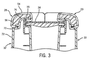
図3は、例示的な実施形態による線5−5(図1を参照)に沿った中央コンソール20の部分的断面図である。上述のように、第1の側部パネル32及び第2の側部パネル33は、硬質性外部表面を有し得る。例示的な実施形態では、硬質性外部表面は、第1のパッド入り部分28及び第2のパッド入り部分29を形成するための基板として機能することが出来る。このため、第1のパッド入り部分28及び第2のパッド入り部分29は、別個の基板なしで形成され、低容積で、費用効率のよい設計をもたらす。以下の記載は、基板上のパッド入り部分を形成するための例示的な工程である。工程は、一般的に且つ第1のパッド入り部分28を参照して説明される。第2のパッド入り部分29を形成するためにも同じ工程が使用され得ることが理解されるべきである。
FIG. 3 is a partial cross-sectional view of the
第1のパッド入り部分28は、外部カバー(又はスキン)54を有し得る。例示的な実施形態では、外部カバー54は、例えばポリウレタン、ポリ塩化ビニル(PVC)、熱可塑性オレフィン(TPO)等の比較的軟質性又は柔軟性のポリマー材料から構成され得る。代替的に、外部カバー54は、ポリマー材料、布地、皮革、複合材料及び/又は人物と物理的に接触する場合に快適性を提供することが出来る任意の他の材料の任意の組合わせから構成されてもよい。1実施形態において、外部カバー54は、約0.5ミリメートルから約3.0ミリメートルの幅の厚みを有し得る。代替的に、外部カバー54は、約1.0ミリメートルから約1.5ミリメートルの幅の厚みを有してもよい。代替的に、任意の他の厚みが使用されてもよい。外部カバー54は、スラッシュ成形工程、真空成形工程、射出成形工程、押し出し工程、鋳造工程(例えば、重力鋳造)、又は当業者に周知の任意の他の適切な工程を使用して製造され得る。
The first padded
第1のパッド入り部分28はまた、パッド(又は充填材)56を有する。例示的な実施形態では、外部カバー54は、空洞が形成されるように第1の側部パネル32に直接取付けられ得る。このため、第1のパッド入り部分28が、同様に第1の側部パネル32に取付けられる追加の基板上に成形される必要がない。追加の基板の排除は、第1のパッド入り部分28の重量及び費用を減少させ、製造工程を単純化し、且つ審美的により魅力的な第1のパッド入り部分28を提供する。例示的な実施形態において、パッド56は、発泡体又はウレタンフォームのような発泡状ポリマー材料であり得る。代替的に、任意の他の軟質性又は準軟質性の材料が使用されてもよい。別の例示的な実施形態では、パッド56は、液体状で外部カバー54と第1側部パネル32との間の空洞内に配置され得る。液状形態は、空洞を満たすために凝固し且つ/又は拡張し得る。空洞内に配置されるパッド56の量は、第1のパッド入り部分28の軟質性、構造、及び/又は形状を調整するためにも使用され得る。1実施形態では、パッド56は、外部カバー54及び/又は第1の側部パネル32と結合するように構成されてもよい。結合は、パッド56と外部カバー54及び/又は第1の側部パネル32との間の化学反応によるものであり得る。代替的に、結合は、パッド56、外部カバー54、及び/又は第1の側部パネル32に適用される接着剤によるものであり得る。
The first padded
図3を参照して例示されるように、第1の側部パネル32は、外部カバー54の端を受け止めるように構成される取付け口70を有する。取付け口70は、摩擦又は締まりばめにより外部カバー54を固定する先細りの隙間、溝、又は堀であり得る。外部カバー54はまた、第1の側部パネル32の内部表面とドア34が取付けられる第1の線路35の上部表面との間で摩擦により固定され得る。代替的な実施形態では、例えばネジ、ボルト、鋲等の1つ以上の締め具が、外部カバー54を第1の側部パネル32に固定するために単独で又は締まりばめに加えて使用され得る。代替的に、接着剤、留め具、又は任意の他の取付け方法が使用されてもよい。別の代替的な実施形態では、第1の側部パネル32は、外部カバー54が固定されるように外部カバー54の一部を受け止めるように構成される1つ以上の開口部を有してもよい。外部カバー54は、外圧により1つ以上の開口部内に押し込まれる。代替的に、外部カバー54は、減圧を使用して1つ以上の開口部に引き込まれ得る。別の代替的な実施形態では、外部カバー54は、第1の側部パネル32のより大きな可視部分が覆われるように、下方に延長され且つ第1の側部パネル32の下方部分72を覆ってもよい。このような実施形態では、外部カバー54は、接着剤、締め具、又は任意の他の取付け方法を使用して第1の側部パネル32の下方部分72に隣接して(すなわち、第1の側部パネル32と外部カバー54との間の空洞なしで)取付けられ得る。別の例示的な実施形態では、外部カバー54は、周囲環境からの実質的に気密及び/又は水密のシールを提供する態様で第1の側部パネル32に取付けられ得る。
As illustrated with reference to FIG. 3, the
取付けられると、外部カバー54及び第1の側部パネル32の上部表面76は、パッド56が配置される空洞を形成する。図3に示されるように、外部カバー54は、パッド56を受け入れるための単一の空洞が形成されるように、2つの場所で第1の側部パネル32に取付けられる。代替的な実施形態では、外部カバー54は、パッド56を受け入れるための複数の空洞が形成されるように、3つ以上の場所で第1の側部パネル56に取付けられてもよい。このため、単一の外部カバーは、複数の別個のパッド入り部分を形成するために使用され得る。単一の外部カバーが使用されるので、複数のパッド入り部分は、堅く、一貫した、且つ審美的に美しい縫い目を有する。車両パネルに取付けられる別の基板を有する従来のパッド入り部分は、このような堅く、一貫した、且つ審美的に美しい外観を達成することが出来ない。
When attached, the
複数のパッド入り部分が、複数の空洞が形成されるように、外部カバーを基板に取付けることにより基板上に形成されてもよい。基板は、複数の実質的に気密の空洞が、基板と外部カバーとの間に形成されるように、外部カバーの部分を受け止め且つ/又は保持するように構成される複数の真空開口部を有し得る。外部カバーは、少なくとも基板の一部の上に設置され、且つ外部カバーが基板に固定され且つ複数の空洞が形成されるように、真空箱が基板内の複数の真空開口部の中に又は隣接して外部カバーを引き込むために使用され得る。代替的に、外部カバーは、締め具、接着剤、またな任意の他の方法を使用して基板に固定され又は取付けられてもよい。パッドは、基板内の1つ以上のパッド開口部を介して複数の空洞内に注入され、つぎ込まれ、或いは挿入され得る。パッド開口部は、複数の空洞への進入路を提供する基板上の任意の場所に配置され得る。外部カバーは、実質的に水密及び気密の態様で基盤に固定されるので、パッドは、真空開口部を介して真空内に引き込まれない。 A plurality of padded portions may be formed on the substrate by attaching an outer cover to the substrate such that a plurality of cavities are formed. The substrate has a plurality of vacuum openings configured to receive and / or hold portions of the outer cover such that a plurality of substantially airtight cavities are formed between the substrate and the outer cover. Can do. The outer cover is placed on at least a portion of the substrate, and the vacuum box is in or adjacent to the plurality of vacuum openings in the substrate such that the outer cover is secured to the substrate and a plurality of cavities are formed. And can be used to retract the outer cover. Alternatively, the outer cover may be secured or attached to the substrate using fasteners, adhesives, or any other method. Pads can be injected, plugged, or inserted into the cavities through one or more pad openings in the substrate. The pad openings can be placed anywhere on the substrate that provides access to multiple cavities. The outer cover is secured to the base in a substantially watertight and airtight manner so that the pad is not drawn into the vacuum through the vacuum opening.
例示的な実施形態では、当業者に周知の複合/アルミニウム工具が、1つ以上の空洞内へのパッドの挿入を実行するために使用され得る。代替的に、任意の他の充填管、挿入装置、ノズル等が使用され得る。基板はまた、充填作業中に1つ以上の空洞に蓄積する可能性がある二酸化炭素又は他のガスの量を減少させるために1つ以上の空洞に隣接する1つ以上の通風孔を有してもよい。一旦パッドが1つ以上の空洞に挿入されると、外部カバーを基板に固定するために使用される任意の減圧は取り除かれてよく、且つ外部カバーは、接着剤、1つ以上の締め具、及び/又は外部カバーとパッドとの間に形成される結合を使用して基板に取付けられ得る。代替的に、外部カバーは、減圧を適用する前に基板に取付けられてもよい。他の代替的な実施形態では、減圧が使用されなくてもよい。1実施形態では、パッド入り部分は、基板が基板を形成するために使用される金型に入っている間に、現場発泡(FIP)を使用して形成されてもよい。代替的に、パッド入り部分は、基板が金型から除去された後に形成されてもよい。代替的な実施形態では、パッド入り部分を形成するために自己皮張り発泡体が使用され得る。自己革張り発泡体は、当業者には周知のように、適用されると自身の皮(又は外部カバー)を形成する任意の発泡体のことを言い得る。自己革張り発泡体は、基板が金型に入っている間に基板に適用され得る。このような実施形態では、外部カバーは、自己革張り発泡体の挿入前に、基板に取付けられない。 In an exemplary embodiment, composite / aluminum tools well known to those skilled in the art may be used to perform pad insertion into one or more cavities. Alternatively, any other filling tube, insertion device, nozzle, etc. can be used. The substrate also has one or more vent holes adjacent to the one or more cavities to reduce the amount of carbon dioxide or other gases that may accumulate in the one or more cavities during the filling operation. May be. Once the pad is inserted into one or more cavities, any reduced pressure used to secure the outer cover to the substrate may be removed, and the outer cover may include an adhesive, one or more fasteners, And / or can be attached to the substrate using a bond formed between the outer cover and the pad. Alternatively, the outer cover may be attached to the substrate before applying the vacuum. In other alternative embodiments, reduced pressure may not be used. In one embodiment, the padded portion may be formed using in-situ foaming (FIP) while the substrate is in the mold used to form the substrate. Alternatively, the padded portion may be formed after the substrate is removed from the mold. In an alternative embodiment, self-skinned foam may be used to form the padded portion. Self-leather foam may refer to any foam that, when applied, forms its skin (or outer cover) when applied. Self-leather foam can be applied to the substrate while the substrate is in the mold. In such embodiments, the outer cover is not attached to the substrate prior to insertion of the self-leather foam.
図4は、例示的な実施形態による中央コンソール20の側面図である。図4に例示されるように、中央コンソール20の可視の上部表面が、部分的に第1のパッド入り部分28の上部表面80によって形成される。上部表面80は、第1のパッド入り部分28の後部端82と第1のパッド入り部分の前部端84の間に配置される。第1のパッド入り部分28は、第1の側部パネル32の上部表面76に取付けられる。第1のパッド入り部分28の上部表面80は、凸部42及び凹部44を有する複合曲線を形成する。凹部44はまた、部分的にシフトレバーパネル22の上部表面によって形成される。このため、上部表面80は、第1のパッド入り部分28の前部端84よりも第1のパッド入り部分28の後部端82において(車両のフレーム又はフロアに対して)より高く持ち上げられる。後部端82におけるより高い高度は、長身の人物により高いアームレストを提供する。同様に、前部端84におけるより低い高度は、背の低い人物により低いアームレストを提供する。例えば、車両の運転席又は乗客席に着座する長身の人物は、彼/彼女が彼/彼女の足に空間を持たせるように、車両の後部に向かって(すなわち、ハンドル74から離れて)彼/彼女の座席を調整する可能性が高い。運転席又は乗客席が、車両の後部に向かって調整されると、長身の人物は、アームレストとして第1のパッド入り部分28(又は第2のパッド入り部分29)の最も高い部分を使用することが出来るように、位置付けられる。背の低い人物に適応するために座席が前方へ(すなわち、ハンドル74に向かって)移動されると、着座した人物は、第1のパッド入り部分28又は第2のパッド入り部分の相応するより低い位置に隣接して位置付けられる。このため、中央コンソール20は、中央コンソール20を上昇又は下降させるための大きく、複雑な調節アセンブリを利用することなく、複数の異なる大きさの人物に適応することが出来る。
FIG. 4 is a side view of the
図5は、例示的な実施形態による中央コンソールの分解図である。分解図には、第1の上部表面102を有する第1の側部パネル100、第2の上部表面106を有する第2の側部パネル104、後部パネル108、シフトレバーパネル110、飲料ホルダ112、インサート114が含まれる。分解図はまた、換気ダクト116、換気カバー118、及び換気制御部120を例示する。換気カバー118及び換気制御部120は、後部座席の乗客が換気を制御できるように、後部パネル108の開口部を介して利用可能である。分解図はさらに、第1の線路122、第2の線路124、第1のドアセグメント126、及び第2のドアセグメント128を例示する。例示的な実施形態では、第1のドアセグメント126及び第2のドアセグメント128は、第1の線路122及び第2の線路124に取付けられ、互いに独立して動作することが出来る。図5の分解図にはまた、第1の上部表面102及び第2の上部表面106を覆うように構成される一片の外部カバー130が例示される。例示的な実施形態では、第1の側部パネル100は、第2の側部パネル104に取付けられることが可能であり、且つ外部カバー130は、単一の空洞が形成されるように第1の側部パネル100及び第2の側部パネル104に取付けられ得る。発泡体は、単一のパッド入り部分が形成されるように、空洞に挿入され得る。
FIG. 5 is an exploded view of a central console according to an exemplary embodiment. The exploded view includes a
本開示のために、「取付け」という用語及びその変形は、2つの(電気的又は機械的)構成部品を互いに直接的に又は間接的に結合することを言い得る。このような結合は、本質的に不動であり又は本質的に可動であってもよい。このような結合は、互いに1つの単一体として一体的に形成される2つの(電気的又は機械的)構成部品及び任意の追加の中間部材を用いて、又は互いに張付けられる2つの構成部品若しくは2つの構成部品及び任意の追加の部材を用いて達成されてもよい。このような結合は、互いに成形される構成部品のように、本質的に持続性であってもよく、代替的に本質的に取り外し可能又は解放可能であってもよい。本開示で用いられるように、「取付け」という用語は、結合、一体化、接続、関係付け、挿入、ぶら下げ、保持、添付、貼り付け、拘束、糊付け、固定、ボルト、釘、接着、ビス、鋲、半田、溶接、及び他の同様の用語を含み得る。 For the purposes of this disclosure, the term “attachment” and variations thereof may refer to the coupling of two (electrical or mechanical) components directly or indirectly to each other. Such a coupling may be essentially stationary or essentially movable. Such a coupling can be achieved by using two (electrical or mechanical) components integrally formed as one single unit with each other and any additional intermediate member, or two components or two attached together. It may be achieved using one component and any additional members. Such a connection may be essentially permanent, such as components molded together, or alternatively may be essentially removable or releasable. As used in this disclosure, the term “attachment” refers to coupling, integration, connection, association, insertion, hanging, holding, attaching, pasting, restraining, gluing, securing, bolts, nails, adhesives, screws, Can include spear, solder, weld, and other similar terms.
本明細書に記載される実施形態は、車両構成部品を参照して記載されている。本明細書に示される構成部品及び方法は、車両用途に限定されないことを理解することが重要である。本明細書に記載される構成部品及び方法はまた、例えば椅子、机、ベンチ、及び他の家具品目等の非車両用途に使用されてもよい。 The embodiments described herein are described with reference to vehicle components. It is important to understand that the components and methods presented herein are not limited to vehicle applications. The components and methods described herein may also be used for non-vehicle applications such as chairs, desks, benches, and other furniture items.
例示的な実施形態の上述の記載は、例示及び説明の目的で提示されている。開示の厳密な形態に対して網羅的又は限定的であることは意図されておらず、上記の教示に照らして修正及び変形が、可能であり又は開示の実施形態の実施から習得され得る。本発明の範囲は、本明細書に添付された請求項及びその均等物によって定義されることが意図される。 The foregoing description of exemplary embodiments has been presented for purposes of illustration and description. It is not intended to be exhaustive or limiting to the precise forms of the disclosure, and modifications and variations are possible or can be learned from the practice of the disclosed embodiments in light of the above teachings. It is intended that the scope of the invention be defined by the claims appended hereto and their equivalents.
Claims (13)
第1の外部カバー及び第1の空洞に配置される第1のパッドを備える第1のパッド入り部分と
を備える中央コンソールであって、
前記第1の空洞が、前記外部カバーの少なくとも一部及び前記上部表面の少なくとも一部によって形成されるように、前記第1の外部カバーが、前記第1のパネルに取付けられ、
前記第1の外部カバーが、締まりばめにより前記第1のパネルの前記取付け口に固定される、中央コンソール。 A first panel having a first upper surface and a mounting opening ;
A central console comprising a first outer cover and a first padded portion comprising a first pad disposed in the first cavity,
The first outer cover is attached to the first panel such that the first cavity is formed by at least a portion of the outer cover and at least a portion of the upper surface ;
A central console , wherein the first outer cover is secured to the mounting opening of the first panel by an interference fit .
第2の上部表面を有する第2の側部パネルと、
第2の空洞が、前記第2の外部カバーの少なくとも一部及び前記第2の上部表面の少なくとも一部によって形成されるように、前記第2の側部パネルに取付けられる第2の外部カバー、及び
前記第2の空洞に配置される第2のパッド
を備える第2のパッド入り部分と
をさらに備える、請求項1に記載の中央コンソール。 The first panel comprises a first side panel;
A second side panel having a second top surface;
A second outer cover attached to the second side panel such that a second cavity is formed by at least a portion of the second outer cover and at least a portion of the second upper surface; The central console of claim 1, further comprising: a second padded portion comprising a second pad disposed in the second cavity.
前記第2の側部パネルに取付けられる第2の線路と、
前記第1の線路及び前記第2の線路に取付けられ且つ前記第1の線路と前記第2の線路との間を摺動するように構成されるドアと
をさらに備え、
前記ドアが、少なくとも前記収納コンパートメントが利用可能であるような解放位置と閉止位置との間を摺動するように構成される、請求項4に記載の中央コンソール。 A first track attached to the first side panel;
A second track attached to the second side panel;
A door attached to the first track and the second track and configured to slide between the first track and the second track;
The central console of claim 4 , wherein the door is configured to slide between an open position and a closed position such that at least the storage compartment is available.
第1の空洞が、前記外部カバーの少なくとも一部及び前記上部表面の少なくとも一部により形成されるように、前記第1のパネルに取付けられる第1の外部カバー、及び
前記第1の空洞に配置される第1のパッド
を備える第1のパッド入り部分と
を備える中央コンソールであって、
前記第1の外部カバーが、締まりばめにより前記第1のパネルの前記取付け口に固定され、
前記第1のパッド入り部分が、前部端、後部端、及び前記前部端及び前記後部端に取付けられる第2の上部表面を有し、前記車両フロアに対して、前記第2の上部表面が、前記後部端において第1の高さ及び前記前部端において第2の高さを有するように形成され、前記第1の高さが前記第2の高さよりも大きい、中央コンソール。 A first panel having a first upper surface and an attachment port , the first panel being attached to a vehicle floor adjacent to a driver's seat of the vehicle;
A first outer cover attached to the first panel, wherein the first cavity is formed by at least a portion of the outer cover and at least a portion of the upper surface; and disposed in the first cavity. A central console comprising a first padded portion comprising a first pad
The first outer cover is fixed to the mounting opening of the first panel by an interference fit;
The first padded portion has a front end, a rear end, and a second upper surface attached to the front end and the rear end, the second upper surface relative to the vehicle floor A central console formed to have a first height at the rear end and a second height at the front end, the first height being greater than the second height.
前記第1のパネル及び前記第2のパネルに取付けられる後部パネルと
をさらに備える、請求項11に記載の中央コンソール。 A second panel having a third upper surface, the second panel being attached to the vehicle floor adjacent to a passenger seat of the vehicle;
The central console of claim 11 , further comprising a rear panel attached to the first panel and the second panel.
Applications Claiming Priority (3)
| Application Number | Priority Date | Filing Date | Title |
|---|---|---|---|
| US87861807P | 2007-01-04 | 2007-01-04 | |
| US60/878,618 | 2007-01-04 | ||
| PCT/US2008/050102 WO2008086089A1 (en) | 2007-01-04 | 2008-01-03 | Integrated soft center floor console |
Publications (2)
| Publication Number | Publication Date |
|---|---|
| JP2010515611A JP2010515611A (en) | 2010-05-13 |
| JP5247722B2 true JP5247722B2 (en) | 2013-07-24 |
Family
ID=39276209
Family Applications (1)
| Application Number | Title | Priority Date | Filing Date |
|---|---|---|---|
| JP2009544969A Expired - Fee Related JP5247722B2 (en) | 2007-01-04 | 2008-01-03 | Integrated soft central floor console |
Country Status (8)
| Country | Link |
|---|---|
| US (1) | US8505997B2 (en) |
| EP (1) | EP2106357B1 (en) |
| JP (1) | JP5247722B2 (en) |
| AT (1) | ATE518694T1 (en) |
| CA (1) | CA2674457C (en) |
| MX (1) | MX2009007176A (en) |
| PL (1) | PL2106357T3 (en) |
| WO (1) | WO2008086089A1 (en) |
Families Citing this family (38)
| Publication number | Priority date | Publication date | Assignee | Title |
|---|---|---|---|---|
| US9481323B2 (en) * | 2008-12-03 | 2016-11-01 | Jason M. Hipshier | Flexible interior trim component having a smooth surface |
| JP2012061915A (en) * | 2010-09-15 | 2012-03-29 | Mazda Motor Corp | Center console structure of vehicle |
| US10464280B2 (en) | 2011-08-30 | 2019-11-05 | Shanghai Yanfeng Jinqiao Automotive Trim Systems Co. Ltd. | Trim component for vehicle interior |
| WO2013033024A2 (en) | 2011-08-30 | 2013-03-07 | Johnson Controls Technology Company | System and method for manufacturing a vehicle trim component via concurrent compression forming and injection molding |
| US8915412B2 (en) * | 2012-03-28 | 2014-12-23 | Toyota Motor Engineering & Manufacturing North America, Inc. | Cup holder assembly |
| US10093268B2 (en) | 2012-08-27 | 2018-10-09 | Shanghai Yanfeng Jinqiao Automotive Trim Systems Co. Ltd. | Trim component for vehicle interior |
| EP3147096B1 (en) | 2012-10-09 | 2018-04-11 | Reliant Worldwide Plastics, LLC | Thermoplastic injection molded element with integral thermoplastic positioning system for reinforced composite structures and process for its manufacturing |
| JP6071477B2 (en) * | 2012-11-29 | 2017-02-01 | しげる工業株式会社 | Vehicle console box |
| US20140167435A1 (en) * | 2012-12-17 | 2014-06-19 | Johnson Controls Technology Company | Movable interior trim component having a retaining feature |
| US9394052B2 (en) | 2013-09-10 | 2016-07-19 | Reliant Worldwide Plastics, Llc | Tray table and method of manufacture |
| JP6156087B2 (en) * | 2013-11-15 | 2017-07-05 | マツダ株式会社 | Center console structure for vehicles |
| US9346407B2 (en) | 2013-12-18 | 2016-05-24 | Nyx, Inc. | Snap-fit vehicle console assembly |
| US9199579B2 (en) | 2014-01-09 | 2015-12-01 | Ford Global Technologies, Llc | Sliding door for a storage bin in a vehicle center floor console |
| CN106460421B (en) * | 2014-02-12 | 2019-02-05 | 江森自控科技公司 | A kind of latch assembly for vehicle chamber door |
| FR3018241B1 (en) * | 2014-03-04 | 2016-03-04 | Mecaplast Sa | CLUTCH PIECE FOR VEHICLE INTERIOR |
| US9950797B2 (en) | 2014-05-02 | 2018-04-24 | Reliant Worldwide Plastics, Llc | Method and system for homogenous thermoplastic seat back assembly |
| JP6285280B2 (en) * | 2014-05-29 | 2018-02-28 | カルソニックカンセイ株式会社 | Console Box |
| WO2015195456A1 (en) * | 2014-06-16 | 2015-12-23 | Reliant Worldwide Plastics, Llc | Method and apparatus for composite thermoplastic arm rest assembly |
| US9902332B2 (en) | 2014-08-12 | 2018-02-27 | Nissan Motor Co., Ltd. | Electromagnetic wave shielding structure of vehicle console |
| JP6437260B2 (en) * | 2014-09-26 | 2018-12-12 | ダイキョーニシカワ株式会社 | Vehicle center console |
| WO2016094621A1 (en) * | 2014-12-10 | 2016-06-16 | Shanghai Yanfeng Jinqiao Automotive Interior Trim Systems Co., Ltd. | Vehicle armrest assembly |
| DE102014226473B4 (en) | 2014-12-18 | 2024-07-11 | Grammer Aktiengesellschaft | Storage compartment, centre console of a vehicle and vehicle with such a storage compartment |
| KR101728334B1 (en) * | 2015-07-02 | 2017-04-20 | 현대자동차주식회사 | Control apparatus for vehicle and vehicle comprising the same |
| US10093215B2 (en) * | 2015-07-14 | 2018-10-09 | Lear Corporation | Vehicle armrest structure with organic fibers |
| WO2017070186A1 (en) | 2015-10-23 | 2017-04-27 | Reliant Worldwide Plastics, Llc | Method and apparatus for a homogeneous thermoplastic leg support |
| WO2017079088A1 (en) | 2015-11-04 | 2017-05-11 | Reliant Worldwide Plastics, Llc | Method and apparatus for a thermoplastic homogeneous failure module |
| US10857922B2 (en) * | 2016-05-20 | 2020-12-08 | Faurecia Interior Systems India Private Limited | Mechanism for holding at least one article in an enclosure |
| US20180118121A1 (en) * | 2016-10-31 | 2018-05-03 | Inoac Usa, Inc. | Automotive interior component such as a tambour door |
| US10106092B2 (en) | 2017-02-09 | 2018-10-23 | Ford Global Technologies, Llc | Expandable and reconfigurable console |
| US9969338B1 (en) * | 2017-03-08 | 2018-05-15 | Howa Kasei Co., Ltd. | Interior component |
| US10232802B2 (en) * | 2017-08-02 | 2019-03-19 | Faurecia Interior Systems, Inc. | Vehicle interior panel with compressible layer of non-uniform thickness |
| US10464493B2 (en) * | 2017-09-13 | 2019-11-05 | Ford Global Technologies, Llc | Deployable door panel receptacle for vehicles |
| US10189414B1 (en) | 2017-10-26 | 2019-01-29 | Ford Global Technologies, Llc | Vehicle storage assembly |
| DE102018218140A1 (en) * | 2017-12-21 | 2019-06-27 | Bos Gmbh & Co. Kg | Covering device for a motor vehicle |
| CN112243416B (en) | 2018-06-28 | 2023-06-27 | 上海延锋金桥汽车饰件系统有限公司 | Component for vehicle interior and method for producing the same |
| US12005690B2 (en) | 2019-04-09 | 2024-06-11 | Karma Automotive Llc | Vehicle interior component |
| DE102020200867A1 (en) * | 2019-10-25 | 2021-04-29 | Brose Fahrzeugteile SE & Co. Kommanditgesellschaft, Coburg | Manually and electrically adjustable device |
| US11904811B2 (en) * | 2021-03-01 | 2024-02-20 | Ford Global Technologies, Llc | Storage assembly for a vehicle |
Family Cites Families (23)
| Publication number | Priority date | Publication date | Assignee | Title |
|---|---|---|---|---|
| US2797739A (en) * | 1953-11-27 | 1957-07-02 | Nello J Orsini | Combined arm rest, table and drawer for vehicle seats |
| US2942649A (en) * | 1957-08-05 | 1960-06-28 | Wells Fay Gillis | Cushion table |
| US3951448A (en) * | 1975-04-21 | 1976-04-20 | Frederick Hawie | Receptacle armrest for motor vehicles |
| JPS59167347A (en) * | 1983-03-12 | 1984-09-20 | Toyota Motor Corp | Console box for car |
| JPS6112454A (en) * | 1984-06-26 | 1986-01-20 | Toyoda Gosei Co Ltd | Console box |
| JPS628141U (en) | 1985-06-29 | 1987-01-19 | ||
| DE3917961C1 (en) | 1989-06-02 | 1990-12-20 | Daimler-Benz Aktiengesellschaft, 7000 Stuttgart, De | Armrest for vehicle seat - has artificial leather covering and removable under-part |
| US5275779A (en) * | 1990-10-03 | 1994-01-04 | Lear Seating Corporation | Method of forming an automotive armrest with cupholder |
| JPH04128941U (en) * | 1991-03-27 | 1992-11-25 | 日本プラスト株式会社 | Console box with armrest |
| JP2541951Y2 (en) * | 1991-09-28 | 1997-07-23 | 関東自動車工業株式会社 | Console box for vehicles |
| DE19524177C1 (en) * | 1995-07-03 | 1996-08-29 | Daimler Benz Ag | Rear seat arm rest for vehicle |
| US5788324A (en) * | 1997-05-20 | 1998-08-04 | Chrysler Corporation | Seat assembly with fold-out armrest |
| JP2001080423A (en) * | 1999-09-10 | 2001-03-27 | Kanto Auto Works Ltd | Console box for automobile |
| US6726267B2 (en) * | 2000-04-25 | 2004-04-27 | Johnson Controls Technology Company | Console assembly |
| US6669260B2 (en) | 2001-05-01 | 2003-12-30 | Johnson Controls Technology Company | Modular system for a vehicle |
| JP4131202B2 (en) * | 2002-07-11 | 2008-08-13 | 豊田合成株式会社 | Console Box |
| FR2863977B1 (en) * | 2003-12-19 | 2007-04-06 | Renault Sas | MODULAR INTERNAL VOLUME CONSOLE FOR MOTOR VEHICLE |
| US7264291B2 (en) * | 2004-09-28 | 2007-09-04 | Lear Corporation | Assembly for supporting an article in a vehicle |
| US7425029B2 (en) * | 2005-01-12 | 2008-09-16 | Lear Corporation | Integral cushioned trim panel for a vehicle |
| JP2006199156A (en) * | 2005-01-20 | 2006-08-03 | Inoac Corp | Console box |
| JP2006298222A (en) * | 2005-04-22 | 2006-11-02 | Calsonic Kansei Corp | Skin affixing structure to cabin interior parts |
| JP4953420B2 (en) * | 2005-12-28 | 2012-06-13 | 日本プラスト株式会社 | Molded product and insert molding method |
| US7762606B2 (en) * | 2008-01-11 | 2010-07-27 | Toyota Motor Engineering & Manufacturing North America, Inc. | One piece instrument panel exhibiting a two grain, two part appearance with surface defined separation groove and associated method for creating a master model for in turn making a production mold for producing multiple instrument panels according to a slush mold process |
-
2008
- 2008-01-03 MX MX2009007176A patent/MX2009007176A/en active IP Right Grant
- 2008-01-03 CA CA2674457A patent/CA2674457C/en not_active Expired - Fee Related
- 2008-01-03 AT AT08713458T patent/ATE518694T1/en not_active IP Right Cessation
- 2008-01-03 PL PL08713458T patent/PL2106357T3/en unknown
- 2008-01-03 EP EP08713458A patent/EP2106357B1/en not_active Not-in-force
- 2008-01-03 JP JP2009544969A patent/JP5247722B2/en not_active Expired - Fee Related
- 2008-01-03 WO PCT/US2008/050102 patent/WO2008086089A1/en active Application Filing
- 2008-01-03 US US12/521,614 patent/US8505997B2/en active Active
Also Published As
| Publication number | Publication date |
|---|---|
| ATE518694T1 (en) | 2011-08-15 |
| CA2674457C (en) | 2014-09-09 |
| CA2674457A1 (en) | 2008-07-17 |
| EP2106357A1 (en) | 2009-10-07 |
| EP2106357B1 (en) | 2011-08-03 |
| PL2106357T3 (en) | 2012-02-29 |
| US20100066115A1 (en) | 2010-03-18 |
| US8505997B2 (en) | 2013-08-13 |
| JP2010515611A (en) | 2010-05-13 |
| MX2009007176A (en) | 2009-07-22 |
| WO2008086089A1 (en) | 2008-07-17 |
Similar Documents
| Publication | Publication Date | Title |
|---|---|---|
| JP5247722B2 (en) | Integrated soft central floor console | |
| US7445261B2 (en) | Console assembly for a vehicle | |
| US20030122392A1 (en) | Vehicle console and storage system and method | |
| US7156437B2 (en) | Automotive trim part with applique and method of making same | |
| US7431365B2 (en) | Console assembly for a vehicle | |
| US8991930B2 (en) | Closed cell foam vehicle interior component and method of making same | |
| US10286818B2 (en) | Dual suspension seating assembly | |
| US5516191A (en) | Desk structure | |
| CN107031472B (en) | Integrated sound system | |
| US7108312B2 (en) | Vehicle door trim bolster with multi-feel cover and method of making the same | |
| US20050248189A1 (en) | Vehicle seat incorporating a seat back panel | |
| US20070075558A1 (en) | Console assembly for a vehicle | |
| US10744918B2 (en) | Tubular console | |
| JP2009521268A (en) | Backrest entertainment display system | |
| US7735913B2 (en) | Cover for vehicle seat handle | |
| US8011714B2 (en) | Stowable seat and seat storage structure | |
| US20060154027A1 (en) | Vehicle door trim bolster with deep-feel cover and method of making the same | |
| KR20100050658A (en) | Apparatus for heating vehicle armrest and method for controlling the same | |
| CN110626286A (en) | Ornament with movable display device | |
| US10829020B2 (en) | Vehicle seating arrangement | |
| CA2883690A1 (en) | Portable padded armrest | |
| US8696058B2 (en) | Adjustable armrest with adjustable cupholder | |
| CN216002425U (en) | Rear seat of vehicle and vehicle | |
| JPH09301014A (en) | Structure of front passenger's set for automobile | |
| US20230415625A1 (en) | Arm rest trash compartment |
Legal Events
| Date | Code | Title | Description |
|---|---|---|---|
| A621 | Written request for application examination |
Free format text: JAPANESE INTERMEDIATE CODE: A621 Effective date: 20101209 |
|
| A977 | Report on retrieval |
Free format text: JAPANESE INTERMEDIATE CODE: A971007 Effective date: 20120524 |
|
| A131 | Notification of reasons for refusal |
Free format text: JAPANESE INTERMEDIATE CODE: A131 Effective date: 20120529 |
|
| A601 | Written request for extension of time |
Free format text: JAPANESE INTERMEDIATE CODE: A601 Effective date: 20120828 |
|
| A602 | Written permission of extension of time |
Free format text: JAPANESE INTERMEDIATE CODE: A602 Effective date: 20120904 |
|
| A521 | Request for written amendment filed |
Free format text: JAPANESE INTERMEDIATE CODE: A523 Effective date: 20120925 |
|
| TRDD | Decision of grant or rejection written | ||
| A01 | Written decision to grant a patent or to grant a registration (utility model) |
Free format text: JAPANESE INTERMEDIATE CODE: A01 Effective date: 20130312 |
|
| A61 | First payment of annual fees (during grant procedure) |
Free format text: JAPANESE INTERMEDIATE CODE: A61 Effective date: 20130409 |
|
| R150 | Certificate of patent or registration of utility model |
Ref document number: 5247722 Country of ref document: JP Free format text: JAPANESE INTERMEDIATE CODE: R150 Free format text: JAPANESE INTERMEDIATE CODE: R150 |
|
| FPAY | Renewal fee payment (event date is renewal date of database) |
Free format text: PAYMENT UNTIL: 20160419 Year of fee payment: 3 |
|
| R250 | Receipt of annual fees |
Free format text: JAPANESE INTERMEDIATE CODE: R250 |
|
| R250 | Receipt of annual fees |
Free format text: JAPANESE INTERMEDIATE CODE: R250 |
|
| R250 | Receipt of annual fees |
Free format text: JAPANESE INTERMEDIATE CODE: R250 |
|
| LAPS | Cancellation because of no payment of annual fees |