JP5242964B2 - Pneumatic tire - Google Patents
Pneumatic tire Download PDFInfo
- Publication number
- JP5242964B2 JP5242964B2 JP2007198173A JP2007198173A JP5242964B2 JP 5242964 B2 JP5242964 B2 JP 5242964B2 JP 2007198173 A JP2007198173 A JP 2007198173A JP 2007198173 A JP2007198173 A JP 2007198173A JP 5242964 B2 JP5242964 B2 JP 5242964B2
- Authority
- JP
- Japan
- Prior art keywords
- turbulent flow
- tire
- protrusion
- flow generating
- ridge
- Prior art date
- Legal status (The legal status is an assumption and is not a legal conclusion. Google has not performed a legal analysis and makes no representation as to the accuracy of the status listed.)
- Active
Links
Images


Description
本発明は、空気入りタイヤに関し、特に、タイヤサイド部の表面にタイヤ径方向に沿って延在され、かつタイヤ周方向に沿って間隔を隔てて形成される複数の乱流発生用突条が設けられる空気入りタイヤに関する。 The present invention relates to a pneumatic tire, and in particular, there are a plurality of turbulent flow generating ridges extending along the tire radial direction on the surface of the tire side portion and formed at intervals along the tire circumferential direction. The present invention relates to a pneumatic tire to be provided.
一般に、空気入りタイヤのタイヤ温度の上昇は、材料の物性変化といった経時的変化の促進、また、高速走行時にはトレッドのブローなど耐久性の観点から好ましいものではない。特に、重荷重での使用となるオフザロードラジアル(ORR)タイヤ、トラックバスラジアル(TBR)タイヤ、またパンク走行時(内圧0kPa走行時)のランフラットタイヤにおいてはその耐久性を向上させるためにタイヤ温度を低減させることが大きな課題となっている。例えば、三日月形補強ゴムを有するランフラットタイヤではパンク走行時に補強ゴムに径方向の変形が集中し、この部分は非常に高温に達し、耐久性に多大な影響を与える。 In general, an increase in the tire temperature of a pneumatic tire is not preferable from the viewpoint of durability such as acceleration of a change over time such as a change in physical properties of a material and a tread blow during high speed running. In particular, off-the-road radial (ORR) tires, truck bus radial (TBR) tires that are used under heavy loads, and run-flat tires during puncturing (running at an internal pressure of 0 kPa) are used to improve their durability. Reducing temperature has become a major issue. For example, in a run-flat tire having a crescent-shaped reinforcing rubber, radial deformation concentrates on the reinforcing rubber during puncturing, and this portion reaches a very high temperature, greatly affecting durability.
このタイヤ温度低減手段としては、タイヤ構成部材の歪低減・抑制を目的とした補強部材の使用により発熱を抑制する手段がある。しかし、補強部材の使用に伴って意図しない故障の発生、また特にランフラットタイヤでは通常内圧走行時の縦バネを高め、乗り心地を悪化させるといった通常性能への影響があり、現在この通常性能を損なわない新たな温度低減手段が求められている。 As the tire temperature reducing means, there is a means for suppressing heat generation by using a reinforcing member for the purpose of reducing and suppressing distortion of the tire constituent member. However, unintended failures occur with the use of reinforcing members, and especially in run-flat tires, there is an effect on normal performance such as increasing the vertical spring during normal internal pressure running and deteriorating the ride comfort. There is a need for a new means for reducing temperature that is not impaired.
その手法としては、PCT/JP2006/318190にあるように、タイヤ表面に乱流促進を温度低減という課題に対し上記タイヤ構成部材からの発熱を抑制する手段ではなく、タイヤの表面形状を変化させることによって冷却効果を向上させるという観点から、タイヤの外表面にタイヤ径方向に長い形状の突起(突形状)を配置することによって冷却効果が向上することが知られている。これは、外表面に生じる空気流れに対して突形状をほぼ垂直に配置することにより、放熱面積の拡大による放熱効果向上よりも、乱流を促進させて冷却効果を向上させることをねらったものである。これは、熱伝導率の悪い材料であるゴムの場合は、放熱面積を拡大させる効果より、乱流を促進させることによる冷却効果の方が大きいためである。
ところが、上記突形状を配置したタイヤで検討を重ねた結果、一方では、突形状の幅が或る値より大きくなると突形状と接するタイヤ表面下部付近で蓄熱による故障が生じ、他方では、突形状の幅が狭過ぎると剛性が低下して充分な乱流を発生させることができないことが分かり、それを改良する手法の探索が課題となっている。 However, as a result of repeated examinations with the tires having the above-mentioned protruding shape, on the one hand, when the width of the protruding shape is larger than a certain value, a failure due to heat storage occurs near the lower portion of the tire surface in contact with the protruding shape. If the width is too narrow, it is found that the rigidity is lowered and sufficient turbulent flow cannot be generated, and the search for a method for improving it is an issue.
そこで、本発明の目的は、乱流発生用突条を形成したことによるタイヤサイド部での蓄熱を抑制しながら空気の流れに対する乱流発生用突条の剛性を向上させた空気入りタイヤを提供することにある。 Accordingly, an object of the present invention is to provide a pneumatic tire in which the rigidity of the turbulent flow generation ridge with respect to the air flow is improved while suppressing heat accumulation at the tire side portion due to the formation of the turbulent flow ridge. There is to do.
問題は、タイヤを構成するゴムが熱伝導性の悪い物質であるから、突起の幅が大きくなると突起が配置される面との接触面(突起の根元付近)で生じる蓄熱によって温度が高くなり、その結果、突起によって発生した乱流により効果的に冷却されている部分に較べて蓄熱部分の温度が相対的に高くなり、それだけ故障が生じ易くなることにある。 The problem is that the rubber that composes the tire is a substance with poor thermal conductivity, so when the width of the protrusion increases, the temperature increases due to heat storage that occurs on the contact surface (near the base of the protrusion) with the surface where the protrusion is placed, As a result, the temperature of the heat storage portion is relatively higher than that of the portion that is effectively cooled by the turbulent flow generated by the protrusions, and the failure is more likely to occur.
しかし、蓄熱を防ぐという課題を解決するには、突起の幅を可能な限り狭くすることが有効であるが、幅を狭くし過ぎると、突起本来の目的である空気の流れと衝突して撹拌し乱流を促進するという機能が阻害される。その理由は、空気と衝突して撹拌し乱流を促進するためには、空気と衝突しても突起がその形状を保ち壁として機能することが必要であるが、幅を狭く(薄く)し過ぎると、剛性が低下し、空気との衝突によって変形し、撹拌機能と乱流促進機能が低下することである。 However, in order to solve the problem of preventing heat storage, it is effective to make the width of the protrusion as narrow as possible. However, if the width is made too narrow, the protrusion will collide with the original air flow and stir The function of promoting turbulence is hindered. The reason for this is that in order to collide with air and stir to promote turbulence, the protrusion must maintain its shape and function as a wall even if it collides with air. If it is too much, the rigidity is lowered, and it is deformed by collision with air, and the stirring function and the turbulent flow promoting function are lowered.
本出願人は、鋭意研究の結果、下記のように、突起に適正な幅を設定することによって、蓄熱の問題を回避しながら充分な温度低減効果が得られることを知見した。 As a result of intensive studies, the present applicant has found that a sufficient temperature reduction effect can be obtained while avoiding the problem of heat storage by setting an appropriate width for the protrusion as described below.
本発明(請求項1)は、先ず、トラックバスラジアル(TBR)タイヤでは、カーカスを構成するカーカス層の折返端部(すなわち、プライ(Ply)端部)近傍、また、サイド補強層を有するランフラットタイヤ1では、タイヤ故障核(タイヤサイド部やビード部)と成り得る部分に適用する目的で、乱流発生用突条(突形状)を設ける範囲をタイヤサイド部に限定している。これは、ゴムの熱伝導率が小さので、冷却効果は乱流発生用突条の直下部分のタイヤサイド部だけに期待されることがその理由である。 According to the present invention (Claim 1), first, in a truck bus radial (TBR) tire, a carcass layer constituting a carcass has a folded end portion (that is, a ply end portion), and a run having a side reinforcing layer. In the flat tire 1, the range in which the turbulent flow generating ridge (projection shape) is provided is limited to the tire side portion for the purpose of being applied to a portion that can be a tire failure nucleus (tire side portion or bead portion). This is because the thermal conductivity of rubber is small and the cooling effect is expected only in the tire side portion immediately below the turbulent flow generating ridge.
なお、上記のタイヤサイド表面とは、乱流発生用突条の頂面の繋がり(ロゴ、装飾帯、サイズ表記などの突起頂面を除く)を指すのではなく、乱流発生用突条の基部に隣接したタイヤサイド部の表面を指している。 The tire side surface mentioned above does not mean the connection of the top surface of the turbulent flow generating ridge (excluding the top surface of the protrusion such as logo, decorative band, size notation, etc.), but the turbulent flow generating ridge. The surface of the tire side part adjacent to the base part is pointed out.
さらに云えば、本発明の特徴は、図3〜図10の各形状例に示すように、乱流発生用突条の幅wを径方向に変化させることによって、課題である突起下(タイヤサイド部において突起に隣接した部分)での蓄熱による故障の防止と、空気の流れに対する突起剛性の向上効果とを両立させたことである。なお、図13に、本発明における乱流発生用突条の諸元(wとhとp)の定義を示している。 Furthermore, the feature of the present invention is that, as shown in each of the shape examples of FIGS. 3 to 10, the width w of the turbulent flow generating ridge is changed in the radial direction, so This is to achieve both the prevention of failure due to heat storage in the portion adjacent to the protrusion in the portion and the improvement effect of the protrusion rigidity against the air flow. FIG. 13 shows definitions of specifications (w, h, and p) of the turbulent flow generating ridge in the present invention.
請求項2記載の発明は、請求項1に記載の空気入りタイヤであって、長手方向における乱流発生用突条の側面である突起側面には、複数の面によりエッジ部が形成されていることを特徴とする。
Invention of
請求項2の構成では、図3〜図6の各形状例のようにA点とC点及びB点とD点との間を直線や曲線で繋ぐのではなく、例えば、図7と図8の形状例のように、A点とC点との間に直線(平面)や曲線(曲面)が交わって生じるエッジ部(不連続線)を意図的に設けることによって、図9(b)が示すように、このエッジ部付近に3次元的な空気の流れを発生させ、冷却効果が更に向上する領域を生み出すことが可能になる。
In the configuration of
請求項3記載の発明は、請求項2に記載の空気入りタイヤであって、エッジ部は、タイヤ回転方向前側に位置することを特徴とする。 A third aspect of the present invention is the pneumatic tire according to the second aspect, wherein the edge portion is located on the front side in the tire rotation direction.
請求項3の構成では、エッジ部をタイヤの回転方向前側に設けたことにより、乱流発生用突条が多量の空気と衝突することになり、それだけ大きな冷却効果が得られる。 In the configuration of the third aspect, by providing the edge portion on the front side in the rotational direction of the tire, the turbulent flow generating ridge collides with a large amount of air, so that a large cooling effect can be obtained.
請求項4の発明は、請求項1乃至請求項3のいずれか1項に記載の空気入りタイヤであって、タイヤサイド部の表面から乱流発生用突条の最も突出する突出位置までの高さである突起高さ(h)は、1〜7mmの範囲を満たすことを特徴とする。
Invention of
乱流による冷却のメカニズムは、乱流発生用突条に衝突した空気流を表面から剥離させ再び表面に衝突させることによって衝突した部分の冷却効果を向上させることであり、本発明はこの冷却効果を第1の目的としている。 The mechanism of cooling by turbulent flow is to improve the cooling effect of the collided part by separating the air flow colliding with the turbulent flow generating ridge from the surface and colliding with the surface again. Is the first purpose.
そこで、請求項4の構成では、空気の流れを乱すために必要な最低限の高さ1mmを下限値にし、また、タイヤサイド部において乱流発生用突条と隣接した部分(接触部付近)で生じる上述の蓄熱は乱流発生用突条の高さが高い程大きくなるから、この影響が許容できる高さ7mmを上限値にし、このように乱流発生用突条の高さの上限値と下限値とを設定したことによって、蓄熱抑制効果と冷却効果とを両立させている。
Therefore, in the configuration of
請求項5の発明は、請求項1乃至請求項4のいずれか1項に記載の空気入りタイヤであって、突起幅(w)は、0.5〜5mmの範囲を満たすことを特徴とする。
Invention of
上述のように、乱流発生用突条は幅wを広げ過ぎると乱流発生用突条との接触部付近での蓄熱が大きくなるから、蓄熱が少ない幅範囲の上限値を5mmとし、下限値は、請求項4で乱流を起こす効果が得られる高さにおいて充分な剛性が得られる値として0.5mmに設定し、蓄熱抑制効果と冷却効果とを両立させている。
As described above, if the ridge for generating turbulent flow is too wide, heat storage near the contact portion with the ridge for generating turbulent flow increases. Therefore, the upper limit of the width range with less heat storage is set to 5 mm. The value is set to 0.5 mm as a value at which sufficient rigidity is obtained at a height at which the effect of causing turbulent flow can be obtained in
請求項6の発明は、請求項1乃至請求項5のいずれか1項に記載の空気入りタイヤであって、タイヤサイド部の表面から乱流発生用突条の最も突出する突出位置までの高さである突起高さを“h”、突起幅を“w”としたときに、0.3≦w/h≦5の関係を満たすことを特徴とする。 Invention of Claim 6 is a pneumatic tire of any one of Claim 1 thru | or 5, Comprising: It is high from the surface of a tire side part to the protrusion position where the protrusion for turbulent flow generation most protrudes. When the height of the protrusion is “h” and the width of the protrusion is “w”, the relationship of 0.3 ≦ w / h ≦ 5 is satisfied.
請求項6は空気の流れに対向するために必要な乱流発生用突条の剛性に関する記述である。空気の流れから受ける力に対抗するのは、乱流発生用突条を或る径方向位置で切断した断面の剪断剛性であり、流れの力を受けたときに生じる乱流発生用突条頂点の動きをある値に制限した場合、この剛性は乱流発生用突条の幅wと高さhとの比w/hに依存する。つまり、幅wに対して高さhが高過ぎると剛性が低下し、流れを乱す壁としての機能を充分に発揮することができない。 The sixth aspect is a description relating to the rigidity of the turbulent flow generating ridge necessary for facing the air flow. It is the shear rigidity of the cross section obtained by cutting the turbulent flow generating ridge at a certain radial position that counteracts the force received from the air flow. This rigidity depends on the ratio w / h between the width w and the height h of the turbulent flow generating ridge. That is, if the height h is too high with respect to the width w, the rigidity is lowered, and the function as a wall that disturbs the flow cannot be sufficiently exhibited.
そこで、検討を行った結果、乱流発生用突条の各径方向位置断面での剛性低下を伴わない範囲としてw/hの下限値を0.3に設定し、また、高さhに対して幅wが大きくなると乱流発生用突条の頂面で生じる剥離した流れとの干渉を防ぐ好適な範囲としてw/hの上限値を5に設定した。 Therefore, as a result of investigation, the lower limit value of w / h was set to 0.3 as a range not accompanied by a decrease in rigidity in each radial position cross section of the turbulent flow generation ridge, When the width w is increased, the upper limit value of w / h is set to 5 as a suitable range for preventing interference with the separated flow generated on the top surface of the turbulent flow generating ridge.
なお、w/hは0.5≦w/h≦1の関係を満たすことが好ましく、この範囲内では剛性低下防止機能と干渉防止機能とがさらに高度に両立する。 Note that w / h preferably satisfies the relationship of 0.5 ≦ w / h ≦ 1, and within this range, the rigidity reduction preventing function and the interference preventing function are more highly compatible.
請求項7の発明は、請求項1乃至請求項6のいずれか1項に記載の空気入りタイヤであって、タイヤサイド部の表面から乱流発生用突条の最も突出する突出位置までの高さである突起高さ(h)の平均値を“H”、乱流発生用突条の長手方向に対して略直交する幅である突起幅(w)の平均値を“W”としたときに、0.6≦W/Hの関係を満たすことを特徴とする。 A seventh aspect of the present invention is the pneumatic tire according to any one of the first to sixth aspects, wherein the height from the surface of the tire side part to the projecting position at which the turbulent flow generating protrusion protrudes most is provided. When the average value of the protrusion height (h) is “H”, and the average value of the protrusion width (w), which is a width substantially perpendicular to the longitudinal direction of the turbulent flow generating ridge, is “W”. And satisfying the relationship of 0.6 ≦ W / H.
なお、突起高さ(h)の平均値及び突起幅(w)の平均値とは、上記w/hを所定間隔(例えば、5mm)ごとに測定し、それを平均した値を示す。 The average value of the protrusion height (h) and the average value of the protrusion width (w) are values obtained by measuring the w / h at predetermined intervals (for example, 5 mm) and averaging them.
空気の流れに対する乱流発生用突条の剛性は、各径方向位置での剛性と共に、乱流発生用突条全体としての剛性が関与する。そこで、最低限の剛性を発揮するための条件として、突起幅wの平均値Wと高さhの平均値Hとの比W/Hの下限値を0.6に設定した。 The rigidity of the turbulent flow generating ridge with respect to the air flow involves the rigidity of the entire turbulent flow generating ridge as well as the rigidity at each radial position. Therefore, as a condition for exhibiting the minimum rigidity, the lower limit value of the ratio W / H between the average value W of the protrusion width w and the average value H of the height h is set to 0.6.
これは、図14のように、乱流発生用突条を上から見たときに、その長さ方向に対して垂直方向に切った断面(例えば、A-A'断面、B-B'断面)でW/Hを長さIの方向に沿って平均した値で評価する。 As shown in FIG. 14, when the turbulent flow generating ridge is viewed from above, a cross section cut in a direction perpendicular to its length direction (for example, an AA ′ cross section or a BB ′ cross section). ) To evaluate W / H as an average value along the length I direction.
請求項8の発明は、請求項1乃至請求項7のいずれか1項に記載の空気入りタイヤであって、複数の乱流発生用突条は、略等間隔に配置されており、タイヤサイド部の表面から乱流発生用突条の最も突出する突出位置までの高さである突起高さを“h”、突起幅を“w”、互いに隣接する乱流発生用突条同士の間隔を“p”としたときに、1.0≦p/h≦50.0、かつ、1.0≦(p−w)/w≦100.0の関係を満たすことを特徴とする。
The invention according to
乱流発生用突条の間隔が狭過ぎると、隣り合った乱流発生用突条の間でタイヤサイド部の表面に流入する空気量が不足して充分な冷却効果が得られず、広過ぎると、タイヤサイド部の全体で乱流発生用突条の個数が不足して充分な冷却効果が得られない。そこで、乱流発生用突条の間隔pと高さhの比p/hを1.0から50.0の範囲に設定することにより、充分な冷却効果を得ている。 If the interval between the turbulent flow generating ridges is too narrow, the amount of air flowing into the surface of the tire side portion between the adjacent turbulent flow generating ridges is insufficient, and a sufficient cooling effect cannot be obtained, which is too wide. In addition, the number of turbulent flow generating ridges is insufficient in the entire tire side portion, and a sufficient cooling effect cannot be obtained. Therefore, a sufficient cooling effect is obtained by setting the ratio p / h between the interval p of the turbulent flow generation protrusions and the height h in the range of 1.0 to 50.0.
また、(p−w)/wは、ピッチ(p)に対する突部の幅の割合を示すものであり、これが小さすぎることは、冷却効果を向上させたい面の面積に対する乱流発生用突条21の表面積の割合が等しくなることと同様である。乱流発生用突条は、ゴムでなり表面積増加による冷却向上効果が期待できないため、(p−w)/wの最小値を1.0に規定している。 Further, (p−w) / w indicates the ratio of the width of the protrusion to the pitch (p), and if this is too small, the ridge for generating turbulent flow with respect to the area of the surface on which the cooling effect is desired to be improved. It is the same as that the ratio of the surface area of 21 becomes equal. Since the turbulent flow generating ridge is made of rubber and cannot be expected to have an effect of improving cooling due to an increase in surface area, the minimum value of (p−w) / w is defined as 1.0.
請求項9の発明は、請求項1乃至請求項8のいずれか1項に記載の空気入りタイヤであって、トレッド幅方向断面において、タイヤサイド部を補強する三日月状のサイド補強層をさらに備えていることを特徴とする。 A ninth aspect of the present invention is the pneumatic tire according to any one of the first to eighth aspects, further comprising a crescent-shaped side reinforcing layer that reinforces the tire side portion in the cross section in the tread width direction. It is characterized by.
故障核に成りうる三日月状サイド補強層を有するタイヤでは、サイド補強層ゴムの最大屈曲部の温度を乱流発生用突条によって低減することにより、耐久性が大きく向上する。 In a tire having a crescent-shaped side reinforcing layer that can become a failure nucleus, durability is greatly improved by reducing the temperature of the maximum bent portion of the side reinforcing layer rubber by the turbulent flow generating ridge.
請求項10の発明は、請求項1乃至請求項9のいずれか1項に記載の空気入りタイヤであって、重荷重用タイヤであることを特徴とする。 A tenth aspect of the invention is the pneumatic tire according to any one of the first to ninth aspects, wherein the pneumatic tire is a heavy load tire.
カーカス層の折返端部(すなわち、プライ(Ply)端部)近傍が故障核に成りうるトラックバスラジアル(TBR)や、オフザロードラジアル(ORR)タイヤのような重荷重用タイヤでは、乱流発生用突条により該折返端部の温度を低減することによって、耐久性が大きく向上する。 For heavy-duty tires such as truck bus radial (TBR) and off-the-road radial (ORR) tires where the carcass layer near the folded end (ie, the ply end) can become a failure nucleus The durability is greatly improved by reducing the temperature of the folded end portion by the protrusion.
本発明によれば、乱流発生用突条の幅を径方向に変化させることによって、突起下(タイヤサイド部において突起に隣接する部分)での蓄熱による故障を防止し、空気の流れに対する突起剛性を向上させることができる。 According to the present invention, by changing the width of the turbulent flow generating ridge in the radial direction, failure due to heat accumulation under the protrusion (a portion adjacent to the protrusion in the tire side portion) is prevented, and the protrusion against the air flow Stiffness can be improved.
次に、本発明に係る空気入りタイヤの一例について、図面を参照しながら説明する。なお、以下の図面の記載において、同一または類似の部分には、同一又は類似の符号を付している。ただし、図面は模式的なのものであり、各寸法の比率などは現実のものとは異なることを留意すべきである。従って、具体的な寸法などは以下の説明を参酌して判断すべきものである。また、図面相互間においても互いの寸法の関係や比率が異なる部分が含まれている。なお、本発明に係る空気入りタイヤは、以下において、ランフラットタイヤ1と示し、重荷重用タイヤであるものとする。 Next, an example of a pneumatic tire according to the present invention will be described with reference to the drawings. In the following description of the drawings, the same or similar parts are denoted by the same or similar reference numerals. However, it should be noted that the drawings are schematic and ratios of dimensions are different from actual ones. Accordingly, specific dimensions and the like should be determined in consideration of the following description. Moreover, the part from which the relationship and ratio of a mutual dimension differ also in between drawings is contained. The pneumatic tire according to the present invention is hereinafter referred to as a run flat tire 1 and is a heavy duty tire.
図1〜図14は、本発明に係る図面であり、図1は、ランフラットタイヤ1の側面図、図2は、ランフラットタイヤ1の要部を径方向に切断した断面図、図3〜図8は、乱流発生用突条の形状例を示す平面図(上面図)、図9(a)は、図8の形状例が形成されたタイヤの側面図、図9(b)は、図8の形状例を示す斜視図、図10は、乱流発生用突条の他の形状例を示す平面図、図11は、乱流発生用突条を内側の表面に設けたタイヤを示す断面図、図12は、乱流発生用突条を内側の表面に設けたタイヤの断面を含む斜視図、図13(a)(b)は、本発明の乱流発生用突条のパラメータを示す図面、図14は、乱流発生用突条のW/Hの定義を説明するための図面、図15〜図18は、乱流発生用突条の断面形状例を示す断面図であり、図19は、乱流発生用突条におけるp/hと熱伝達率との関係を示す図、図20は、乱流発生用突条における(p−w)/wと熱伝達率の関係を示す図、図21は、径方向に対する乱流発生用突条の傾き角度θと熱伝達率との関係を示す図である。 1 to 14 are drawings according to the present invention, FIG. 1 is a side view of the run-flat tire 1, FIG. 2 is a cross-sectional view in which a main part of the run-flat tire 1 is cut in a radial direction, and FIGS. FIG. 8 is a plan view (top view) showing an example of the shape of the turbulent flow generating ridge, FIG. 9 (a) is a side view of the tire formed with the example of FIG. 8, and FIG. 8 is a perspective view showing an example of the shape of FIG. 8, FIG. 10 is a plan view showing another example of the shape of the ridge for generating turbulent flow, and FIG. 11 shows a tire provided with the ridge for generating turbulent flow on the inner surface. 12 is a perspective view including a cross section of a tire provided with a turbulent flow generating ridge on the inner surface, and FIGS. 13A and 13B show parameters of the turbulent flow generating ridge of the present invention. FIG. 14 is a drawing for explaining the definition of W / H of a turbulent flow generating ridge, and FIGS. 15 to 18 are sectional views showing examples of the cross-sectional shape of the turbulent flow generating ridge. FIG. 19 is a diagram showing the relationship between p / h and heat transfer coefficient in the turbulent flow generating ridge, and FIG. 20 shows the relationship between (pw) / w and heat transfer coefficient in the turbulent flow generating ridge. FIG. 21 and FIG. 21 are diagrams showing the relationship between the inclination angle θ of the turbulent flow generation protrusion with respect to the radial direction and the heat transfer coefficient.
〈ランフラットタイヤの概略構成〉
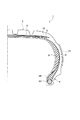
図1及び図2に示すように、ランフラットタイヤ1は、路面と接触するトレッド部2と、タイヤ両側のタイヤサイド部3と、それぞれのタイヤサイド部3の開口縁に沿って設けられたビード部4とを備えて大略構成されている。タイヤサイド部3の外側表面には、タイヤ径方向に沿って延在され、かつタイヤ周方向に沿って間隔を隔てて(略等間隔に)配列された複数の乱流発生用突条20が突設されている。
<Schematic configuration of run-flat tire>
As shown in FIGS. 1 and 2, the run-flat tire 1 includes a
図2に示すように、ビード部4は、タイヤサイド部3の開口部の縁部に沿って周回するように設けられたビードコア6A及びビードフィラー6Bを備えている。ビードコア6Aとしては、具体的にスチールコードなどが用いられている。
As shown in FIG. 2, the
また、ランフラットタイヤ1は、タイヤの骨格となるカーカス層7を有している。タイヤサイド部3に位置するカーカス層7の内側(タイヤ幅方向内側)には、補強ゴムとしてのサイド補強層8(三日月状のサイド補強層)が設けられている。このサイド補強層8は、タイヤ幅方向断面において三日月形状のゴムストックによって形成されている。
The run-flat tire 1 has a
カーカス層7のタイヤ径方向外側には複数層のベルト層(スチールベルト補強層9,10、周方向補強層11)が設けられており、上記のトレッド部2は周方向補強層11のタイヤ径方向外側に設けられている。
A plurality of belt layers (steel
〈乱流発生用突条の構成〉
乱流発生用突条20は、乱流を発生又は促進させるものであり、すなわち、タイヤサイド部3の温度を低減させ、蓄熱を抑制するものである。例えば、トラックバスラジアル(TBR)タイヤでは、カーカス層7の折返端部(すなわち、プライ(Ply)端部)近傍の温度や、サイド補強層8を有するランフラットタイヤでは、タイヤ故障核(タイヤサイド部3やビード部4)と成り得る部分の温度を低減して、耐久性を向上させる観点から特に有効である。
<Structure of turbulent ridges>
The turbulent
乱流発生用突条20は、タイヤサイド部3においてタイヤ径方向に沿って細長く延伸するように形成されており、延在方向(すなわち、タイヤ周方向)に略直交する周方向断面形状が矩形状に形成されている(図13(b)参照)。
The turbulent
(第1の形状例)
図3は、ランフラットタイヤ1のタイヤサイド部3に形成された乱流発生用突条20の第1の形状例である乱流発生用突条21を示している。
(First shape example)
FIG. 3 shows a turbulent
乱流発生用突条21は、タイヤサイド部3の表面にタイヤ径方向に沿って延在され、かつタイヤ周方向に沿って間隔を隔てて形成されている。また、乱流発生用突条21は長手方向に対して略直交する幅である突起幅wを長手方向で変化させている。
The turbulent
図3は乱流発生用突条21を上面から見ており、乱流発生用突条21はそれぞれA−CとB−Dからなる略径方向の2平面(突起側面)とそれぞれA−BとD−Cからなる周方向の2平面(突起側面)から構成され、その幅wを径方向外側(トレッド部2側)に向かって広がるように変化させている。また、乱流発生用突条21は中心線211を径方向と一致させたことにより、周方向(回転方向)の両側で対称的な形に形成されている。
FIG. 3 shows the turbulent
このように、乱流発生用突条21は、幅wを径方向外側(トレッド部2側)に向かって広がるように変化させた(適正な幅を設定した)ことにより、幅wが大き過ぎることに起因するタイヤサイド部3との接触面での蓄熱による温度上昇と、幅wが狭過ぎることによる剛性低下とを回避し、蓄熱抑制機能と乱流促進機能(冷却機能)とを両立させている。
As described above, the width w of the turbulent
また、乱流発生用突条21は、タイヤサイド部3の表面から最も突出する突出位置までの高さである突起高さhが1〜7mmの範囲を満たすように設定されている。
The turbulent
下限値の1mmは空気の流れを乱すために必要な最低限の高さhであり、上限値の7mmはタイヤサイド部3の乱流発生用突条21との接触部付近の蓄熱の影響が許容できる高さhであり、乱流発生用突条21はこのように高さhの上限値と下限値とを設定したことによって、蓄熱抑制効果と冷却効果とを両立させている。
The lower limit value of 1 mm is the minimum height h necessary for disturbing the air flow, and the upper limit value of 7 mm is affected by the heat storage near the contact portion with the
また、乱流発生用突条21の突起幅wは、0.5〜5mmの範囲を満たすように設定されている。
The protrusion width w of the turbulent
5mmは乱流発生用突条21との接触部付近での蓄熱が少ない幅範囲の上限値であり、0.5mmは乱流を起こす効果が得られる高さにおいて充分な剛性が得られる範囲の下限値であり、こうして、上限値と下限値を設定することにより蓄熱抑制効果と冷却効果とを両立させている。
5 mm is the upper limit of the width range in which the heat storage near the contact portion with the turbulent
また、乱流発生用突条21は、突起高さhと突起幅wとの比(w/h)が0.3≦w/h≦5の関係を満たすように設定されている。
The turbulent
乱流発生用突条21が空気流れの力を受けたときの剛性はその幅wと高さhとの比w/hに依存する。そこで、乱流発生用突条21はw/hの下限値を0.3に設定して各径方向位置断面での剛性低下を抑制し、上限値を5に設定して高さhに対し幅wが大きくなったときに乱流発生用突条21の頂面で生じる剥離流れとの干渉を防いでいる。
The rigidity when the turbulent
なお、w/hは0.5≦w/h≦1の関係を満たすことが好ましく、下限値を0.5に設定し上限値を1に設定することにより、径方向位置断面での剛性低下抑制効果及び剥離流れとの干渉防止効果がさらに向上する。 Note that w / h preferably satisfies the relationship of 0.5 ≦ w / h ≦ 1, and by setting the lower limit value to 0.5 and the upper limit value to 1, the rigidity in the radial position cross section is reduced. The suppression effect and the effect of preventing interference with the separation flow are further improved.
また、図13に示すように、突起高さを“h”、突起幅を“w”、互いに隣接する乱流発生用突条21同士の間隔を“p”としたときに、1.0≦p/h≦50.0、かつ、1.0≦(p−w)/w≦100.0の関係に設定することが好ましい。特に、2.0≦p/h≦24.0の関係に設定することが好ましく、10.0≦p/h≦20.0の関係に設定することがさらに好ましく、かつ、4.0≦(p−w)/w≦39.0の関係に設定することが好ましい。
As shown in FIG. 13, when the height of the protrusion is “h”, the width of the protrusion is “w”, and the interval between adjacent turbulent
上記のように、p/hで規定される空気の流れ(乱流)は、ピッチ(p)を細かく刻み過ぎると、すなわちピッチ(p)を狭くすると、溝底部に空気の流れが入り込まず、ピッチ(p)を広げすぎると乱流発生用突条21の形状加工が無い場合と同等となってしまうため、上記した数値範囲に設定することが好ましい。
As described above, if the air flow (turbulent flow) defined by p / h is finely divided into pitches (p), that is, if the pitch (p) is narrowed, the air flow does not enter the groove bottom, If the pitch (p) is excessively widened, the turbulent
また、(p−w)/wは、ピッチ(p)に対する突部の幅の割合を示すものであり、これが小さすぎることは、冷却効果を向上させたい面の面積に対する乱流発生用突条21の表面積の割合が等しくなることと同様である。乱流発生用突条21は、ゴムでなり表面積増加による冷却向上効果が期待できないため、(p−w)/wの最小値を1.0に規定している。
Further, (p−w) / w indicates the ratio of the width of the protrusion to the pitch (p), and if this is too small, the ridge for generating turbulent flow with respect to the area of the surface on which the cooling effect is desired to be improved. It is the same as that the ratio of the surface area of 21 becomes equal. Since the turbulent
乱流発生用突条21のタイヤ径方向に対する角度(θ)、すなわち、中心線211からの傾く角度(θ)は、−70°≦θ≦70°の範囲に設定することが好ましい。ランフラットタイヤ1は、回転体であるため、タイヤサイド部3の表面での空気の流れは、遠心力により径方向外側に向かっている。つまり、乱流発生用突条21の空気の流入に対し背面側の澱み部分を低減し冷却を向上させるため、乱流発生用突条21のタイヤ径方向に対する角度(θ)を上記角度範囲に設定することが好ましい。
The angle (θ) of the turbulent
なお、乱流発生用突条21のタイヤ径方向に対する角度(θ)は、回転体である空気入りタイヤのタイヤ径方向位置により空気の流れの速度が若干異なるため、各乱流発生用突条21が異なる角度(θ)に設定してもよい。
The angle (θ) of the turbulent
加えて、乱流発生用突条21は、延在方向に沿って不連続に分割されている構成であってもよく、タイヤ周方向に沿って不均一に配置された構成であってもよい。タイヤサイド部3の表面に設けられる乱流発生用突条21の空気の流入に対して、タイヤ回転方向に対する後側(すなわち、背面側)では澱みが生じて、該乱流発生用突条21が設けられていない場合と比べて、冷却効果が悪化する部分が生じる。この冷却効果が悪化する部分を削減して平均的な熱伝達率を向上させるには、乱流発生用突条21が延在方向に不連続に分割されていることが有効となる。
In addition, the turbulent
また、乱流発生用突条21は、突起高さhの平均値である“H”と突起幅wの平均値である“W”との比W/Hが0.6≦W/Hの関係を満たすように設定されている。
The turbulent
空気の流れに対する乱流発生用突条21の剛性は、各径方向位置での剛性と共に、乱流発生用突条21全体としての剛性が関与する。そこで、W/Hの下限値を0.6に設定したことにより乱流発生用突条21は最低限の剛性(上記w/hの平均値)を得ている。
The rigidity of the turbulent
なお、W/Hは、図14のように、乱流発生用突条を上から見たとき、その長さ方向に対して垂直方向に切った断面(例えば、A-A'断面、B-B'断面)でW/Hを長さIの方向に沿って平均した値で評価する。 As shown in FIG. 14, W / H is a cross-section (for example, AA ′ cross-section, B--B cross section cut perpendicularly to the length direction when the turbulent flow generating ridge is viewed from above. B / H) is evaluated as a value obtained by averaging W / H along the length I direction.
また、上記のようにランフラットタイヤ1は、タイヤサイド部3を補強するサイド補強層8を備えており、サイド補強層8は故障核に成りうるが、乱流発生用突条21によってサイド補強層8の最大屈曲部の温度が低減され、その結果、耐久性が大きく向上している。
Further, as described above, the run-flat tire 1 includes the
また、ランフラットタイヤ1は、上記のように重荷重用タイヤであり、カーカス層7の折返端部(すなわち、プライ(Ply)端部)近傍が故障核に成りうるトラックバスラジアル(TBR)の場合、乱流発生用突条21によってカーカス層7の折返端部近傍の温度上昇が抑制されることによって、耐久性が大きく向上する。
The run-flat tire 1 is a heavy-duty tire as described above, and is a track bus radial (TBR) in which the vicinity of the folded end portion (that is, the ply end portion) of the
(第2の形状例)
図4は、ランフラットタイヤ1のタイヤサイド部3に形成された乱流発生用突条20の第2の形状例である乱流発生用突条22を示している。
(Second shape example)
FIG. 4 shows a turbulent
乱流発生用突条22は、タイヤサイド部3の表面にタイヤ径方向に沿って延在され、かつタイヤ周方向に沿って間隔を隔てて形成されている。また、乱流発生用突条22は長手方向に対して略直交する幅である突起幅wを長手方向で変化させている。
The turbulent
図4は乱流発生用突条22を上面から見ており、乱流発生用突条22はそれぞれA−CとB−Dからなる略径方向の2平面(突起側面)とそれぞれA−BとD−Cからなる周方向の2平面(突起側面)から構成され、その幅wを径方向外側(トレッド部2側)に向かって狭くなるように変化させている。また、乱流発生用突条22は中心線221を径方向と一致させたことにより、周方向(回転方向)の両側で対称的な形に形成されている。
FIG. 4 shows the turbulent
このように構成したこと、及び、高さh、幅w、これらの平均値HとW、間隔pなどのパラメータを各請求項のように限定することによって、乱流発生用突条22は、上述した第1の形状例に係る乱流発生用突条21と同等の効果が得られる。
By configuring in this way and by limiting the parameters such as height h, width w, average values H and W thereof, interval p, etc. as in each claim, the turbulent
(第3の形状例)
図5は、ランフラットタイヤ1のタイヤサイド部3に形成された乱流発生用突条20の第3の形状例である乱流発生用突条23を示している。
(Third shape example)
FIG. 5 shows a turbulent
乱流発生用突条23は、タイヤサイド部3の表面にタイヤ径方向に沿って延在され、かつタイヤ周方向に沿って間隔を隔てて形成されている。また、乱流発生用突条23は長手方向に対して略直交する幅である突起幅wを長手方向で変化させている。
The turbulent
図5は乱流発生用突条23を上面から見ており、乱流発生用突条23はそれぞれA−CとB−Dからなる略径方向の2平面(突起側面)とそれぞれA−BとD−Cからなる周方向の2平面(突起側面)から構成され、その幅wを径方向外側(トレッド部2側)に向かって広がるように変化させている。また、乱流発生用突条23はA−C平面を通る線231が径方向と一致するように形成されている。
In FIG. 5, the turbulent
このように構成したこと、及び、高さh、幅w、これらの平均値HとW、間隔pなどのパラメータを各請求項のように限定することによって、乱流発生用突条23は、上述した第1の形状例に係る乱流発生用突条21と同等の効果が得られる。
By configuring in this way and by limiting the parameters such as height h, width w, average values H and W thereof, interval p, etc. as in each claim, the turbulent
また、上記のように、線231に関して周方向に非対称に形成された乱流発生用突条23は、B−D平面をランフラットタイヤ1の回転方向側に配置しても、回転方向の反対側に配置してもよく、これらの間で異なった蓄熱抑制機能と乱流促進機能(冷却機能)とを期待できる。
Further, as described above, the turbulent
(第4の形状例)
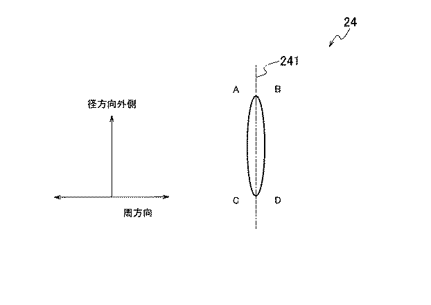
図6は、ランフラットタイヤ1のタイヤサイド部3に形成された乱流発生用突条20の第4の形状例である乱流発生用突条24を示している。
(Fourth shape example)
FIG. 6 shows a turbulent
乱流発生用突条24は、タイヤサイド部3の表面にタイヤ径方向に沿って延在され、かつタイヤ周方向に沿って間隔を隔てて形成されている。また、乱流発生用突条24は長手方向に対して略直交する幅である突起幅wを長手方向で変化させている。
The turbulent
図6は乱流発生用突条24を上面から見ており、乱流発生用突条24はそれぞれA−CとB−Dからなる2曲面(突起側面)によって構成され、略径方向に設けられている。また、乱流発生用突条24は中心線241を径方向と一致させたことにより、周方向(回転方向)の両側で対称的な形に形成されている。
In FIG. 6, the turbulent
このように構成したこと、及び、高さh、幅w、これらの平均値HとW、間隔pなどのパラメータを各請求項のように限定することによって、乱流発生用突条24は、上述した第1の形状例に係る乱流発生用突条21と同等の効果が得られる。
By configuring in this way and by limiting the parameters such as the height h, the width w, and the average values H and W thereof, and the interval p as in the claims, the turbulent
(第5の形状例)
図7は、ランフラットタイヤ1のタイヤサイド部3に形成された乱流発生用突条20の第5の形状例である乱流発生用突条25を示している。
(Fifth shape example)
FIG. 7 shows a turbulent
乱流発生用突条25は、タイヤサイド部3の表面にタイヤ径方向に沿って延在され、かつタイヤ周方向に沿って間隔を隔てて形成されている。また、乱流発生用突条25は長手方向に対して略直交する幅である突起幅wを長手方向で変化させている。
The turbulent
図7は乱流発生用突条25を上面から見ており、乱流発生用突条25はそれぞれA−EとB−Dからなる略径方向の2平面(突起側面)とそれぞれA−BとD−Cからなる周方向の2平面(突起側面)とEとCを結ぶ平面(突起側面)から構成され、その幅wを径方向外側(トレッド部2側)に向かって広くなるように変化させている。
In FIG. 7, the turbulent
また、乱流発生用突条25は、A−E平面とE−C平面をランフラットタイヤ1の回転方向に向けて(回転方向前面に)配置されており、A−E平面とE−C平面(複数の面)とによってエッジ部251が形成されている。
The turbulent
乱流発生用突条25は、図3〜図6の各形状例のようにA点とC点との間を直線や曲線で繋ぐのではなく、A点とC点との間にA−E平面とE−C平面との交線(不連続線)によりエッジ部251を意図的に形成することによって、エッジ部251の付近に3次元的な空気の流れ(乱流)を発生させ、この領域での冷却効果をさらに向上させている。
The turbulent
また、エッジ部251を回転方向の前面に向けて配置したことにより、乱流発生用突条25のA−E平面とエッジ部251とE−C平面とが多量の空気と衝突することになり、かつ遠心力によりタイヤ径方向内側から外側へ向かう空気をエッジ部251で剥離させてさらに加速させることになり、それだけ大きな冷却効果を得ている。
In addition, since the
このように構成したこと、及び、高さh、幅w、これらの平均値HとW、間隔pなどのパラメータを各請求項のように限定することによって、乱流発生用突条25は、上述した第1の形状例に係る乱流発生用突条21と同等の効果が得られる。
By configuring in this way and by limiting the parameters such as height h, width w, average values H and W thereof, and interval p as in the respective claims, the turbulent
(第6の形状例)
図8は、ランフラットタイヤ1のタイヤサイド部3に形成された乱流発生用突条20の第6の形状例である乱流発生用突条26を示しており、図9(a)は、乱流発生用突条26が形成されたタイヤの側面図、図9(b)は、乱流発生用突条26を示す斜視図である。
(Sixth shape example)
FIG. 8 shows a turbulent
乱流発生用突条26は、タイヤサイド部3の表面にタイヤ径方向に沿って延在され、かつタイヤ周方向に沿って間隔を隔てて形成されている。また、乱流発生用突条26は長手方向に対して略直交する幅である突起幅wを長手方向で変化させている。
The turbulent
図8は乱流発生用突条26を上面から見ており、乱流発生用突条26はそれぞれA−EとF−CとB−Dからなる略径方向の平面(突起側面)とそれぞれA−BとD−Cからなる周方向の2平面(突起側面)とEとFを結ぶ平面(突起側面)から構成され、その幅wを径方向外側(トレッド部2側)に向かって広くなるように変化させている。
In FIG. 8, the turbulent
また、乱流発生用突条26は、A−E平面とE−F平面とF−C平面をランフラットタイヤ1の回転方向に向けて(回転方向前面に)配置されており、A−E平面とE−F平面(複数の面)とによってエッジ部261が形成され、E−F平面とF−C平面(複数の面)とによってエッジ部262が形成されている。
Further, the turbulent
乱流発生用突条26は、A点とC点との間に2個所のエッジ部261,262を設けたことにより、図9(b)のように、空気の流れ263によってエッジ部261,262の付近に乱流264(3次元的な空気の流れ)が発生し、この領域で冷却効果がさらに向上している。
As shown in FIG. 9B, the turbulent
また、エッジ部261,262を回転方向の前面に向けて配置したことにより、乱流発生用突条26のA−E平面とエッジ部261とE−F平面とエッジ部262とF−C平面とが多量の空気と衝突することになり、かつ遠心力によりタイヤ径方向内側から外側へ向かう空気をエッジ部261,262で剥離させてさらに加速させることになり、それだけ大きな冷却効果を得ている。
Further, by arranging the
このように構成したこと、及び、高さh、幅w、これらの平均値HとW、間隔pなどのパラメータを各請求項のように限定することによって、乱流発生用突条26は、上述した第1の形状例に係る乱流発生用突条21と同等の効果が得られる。
By configuring in this way and by limiting the parameters such as the height h, the width w, and the average values H and W thereof, the interval p, etc. as in each claim, the turbulent
(第7の形状例)
図10は、ランフラットタイヤ1のタイヤサイド部3に形成された乱流発生用突条20の第7の形状例である乱流発生用突条27を示している。
(Seventh shape example)
FIG. 10 shows a turbulent
乱流発生用突条27は、タイヤサイド部3の表面にタイヤ径方向に沿って延在され、かつタイヤ周方向に沿って間隔を隔てて形成されている。また、乱流発生用突条27は長手方向に対して略直交する幅である突起幅wを長手方向で変化させている。
The turbulent
図10は乱流発生用突条27を上面から見ており、乱流発生用突条27はそれぞれA−EとF−GとH−IとJ−KとL−CとB−Dの各平面からなる略径方向の平面(突起側面)とそれぞれA−BとC−DとE−FとG−HとI−JとK−Lとからなる周方向の平面(突起側面)とから構成されている。
FIG. 10 shows the turbulent
また、乱流発生用突条27は、A点からC点の間の上記各平面をランフラットタイヤ1の回転方向に向けて(回転方向前面に)配置されており、A点からC点の間の各平面の交わりによって8個所のエッジ部271,272,273,274,275,276,277,278が形成されている。
Further, the turbulent
乱流発生用突条27は、上記のようにA点とC点との間に8個所のエッジ部271,272,273,274,275,276,277,278を設けたことにより、空気の流れによって各エッジ部付近に乱流(3次元的な空気の流れ)が発生し、この領域で冷却効果が大きく向上している。
The turbulent
また、各エッジ部を回転方向の前面に向けて配置したことにより、乱流発生用突条27のA点からC点を結ぶ各平面と各エッジ部とが多量の空気と衝突することになり、かつ遠心力によりタイヤ径方向内側から外側へ向かう空気を各エッジ部271,272,273,274,275,276,277,278で剥離させてさらに加速させることになり、極めて大きな冷却効果を得ている。
Further, since each edge portion is arranged toward the front surface in the rotation direction, each plane connecting point A to point C of the turbulent
このように構成したこと、及び、高さh、幅w、これらの平均値HとW、間隔pなどのパラメータを各請求項のように限定することによって、乱流発生用突条27は、上述した第1の形状例に係る乱流発生用突条21と同等の効果が得られる。
By configuring in this way and by limiting the parameters such as the height h, the width w, and the average values H and W thereof, the interval p, etc. as in each claim, the turbulent
ここで、本発明に係る乱流発生用突条20は、図11及び図12に示すように、ランフラットタイヤ1の内側表面に形成してもよく、一般に、タイヤの温度分布は内面に近づく程高くなる傾向にあり、従って、内面に乱流発生用突条20を形成して高温の部分を冷却すれば、ランフラットタイヤ1全体の冷却効果がそれだけ向上する。
Here, as shown in FIGS. 11 and 12, the turbulent
また、乱流発生用突条20は、ランフラットタイヤ1の外面と内面の両方に同時に形成してもよい。この場合、外面と内面で互いの位置が重ならないように(例えば、外面と内面の蓄熱部分を互いの乱流発生用突条20が冷却し合うような位置に配置すれば、ランフラットタイヤ1全体の冷却効果がさらに向上する。
Further, the turbulent
また、タイヤの内面に形成する場合でも、乱流発生用突条20は、高さh、幅w、これらの平均値HとW、間隔pなどのパラメータを各請求項のように限定し、各限定による効果を得ることができる。
Further, even when formed on the inner surface of the tire, the turbulent
[その他の実施の形態]
上述したように、本発明の実施の形態を通じて本発明の内容を開示したが、この開示の一部をなす論述及び図面は、本発明を限定するものであると理解すべきではない。
[Other embodiments]
As described above, the contents of the present invention have been disclosed through the embodiments of the present invention. However, it should not be understood that the descriptions and drawings constituting a part of this disclosure limit the present invention.
具体的には、ランフラットタイヤ1は、サイド補強層8を有し、かつ重荷重タイヤであるものとして説明したが、これに限定されるものではなく、サイド補強層8を有していない(例えば、オフザロードラジアルタイヤ(ORR)やトラック・バスラジアルタイヤ(TBR))ものであっても勿論よい。
Specifically, the run-flat tire 1 has been described as having a
また、乱流発生用突条20は、タイヤサイド部3全体に設けられているものとして説明したが、これに限定されるものではなく、例えば、タイヤ最大幅の位置、又は、ビードフィラー6Bの前記タイヤ径方向外側の位置に設けられていても勿論よい。
Further, the turbulent
さらに、乱流発生用突条20は、上記した実施の形態及び形状例では、周方向断面形状が矩形状であるとしたが、これに限定されるものではない。例えば、乱流発生用突条20の周方向断面形状は、図15(a)〜図15(c)に示すように、略台形であってもよく、
図16(a)及び図16(b)に示すように、略三角形でであってもよく、図17(a)及び図17(b)に示すように、段差20aを有する段付き形状であってもよく、図18(a)〜図18(e)に示すように、延在方向に略直交する方向(すなわち、略タイヤ径方向)に貫通する貫通孔20bを有する形状であっても勿論よい。
Furthermore, although the turbulent
As shown in FIGS. 16 (a) and 16 (b), it may be substantially triangular, and as shown in FIGS. 17 (a) and 17 (b), it has a stepped shape having a step 20a. 18 (a) to 18 (e), of course, the shape may include a through
この開示から当業者には様々な代替実施の形態、実施例及び運用技術が明らかとなろう。したがって、本発明の技術的範囲は、上述の説明から妥当な特許請求の範囲に係る発明特定事項によってのみ定められるものである。 From this disclosure, various alternative embodiments, examples and operational techniques will be apparent to those skilled in the art. Therefore, the technical scope of the present invention is defined only by the invention specifying matters according to the scope of claims reasonable from the above description.
次に、表1と表2によって実施例の説明をする。 Next, examples will be described with reference to Tables 1 and 2.
各表のように1個の従来例と6個の実施例と5個の比較例の乱流発生用突条を形成したランフラットタイヤについて、以下の条件で耐久ドラム試験を行い、故障発生までの耐久距離であるその結果(ランフラット耐久性評価)を、従来例を100として指数化し、各実施例と各比較例の指数を表1と表2に示した。 As shown in each table, endurance drum tests were conducted on the run-flat tires with the turbulent flow generating ridges of one conventional example, six examples, and five comparative examples until the failure occurred. The results (run-flat durability evaluation), which are the endurance distances, were indexed with the conventional example being 100, and the indices of the examples and comparative examples are shown in Tables 1 and 2.
なお、従来例の乱流発生用突条は各パラメータが本発明の範囲に入るが、突起幅wは長手方向で変化させずエッジ部もないものであり、実施例1〜6の各乱流発生用突条は突起幅wを長手方向で変化させ、各パラメータを本発明の範囲内から選定し、エッジ部を設けたものであり、比較例1〜5の各乱流発生用突条はエッジ部はあるが各パラメータのいずれかを本発明の範囲外から選んだものである。 The ridges for generating turbulent flow in the conventional example have respective parameters within the scope of the present invention, but the protrusion width w does not change in the longitudinal direction and there is no edge portion. The generating ridge is obtained by changing the protrusion width w in the longitudinal direction, selecting each parameter from the scope of the present invention, and providing an edge portion. Although there is an edge portion, any one of the parameters is selected from outside the scope of the present invention.
(耐久ドラム試験に用いたランフラットタイヤの諸元)
タイヤサイズ:285/50R20
使用リム :8JJ×20
(耐久力試験の条件)
内圧:0kPa
荷重:9.8kN
速度:90km/h
必要パラメータ:w、h、p、w/h、p/h
Tire size: 285 / 50R20
Rim used: 8JJ × 20
(Conditions for durability test)
Internal pressure: 0 kPa
Load: 9.8kN
Speed: 90km / h
Required parameters: w, h, p, w / h, p / h
表1から、突起幅wを長手方向で変化させ、各パラメータを本発明の範囲内から選定し、エッジ部を設けた各実施例は、突起幅wを長手方向で変化させずエッジ部もない従来例と較べて、タイヤの耐久性が大きく向上していることが分かり、特に、w/hを好ましい範囲である0.5〜1の範囲で選んだことによる効果が大きいことが分かる。 From Table 1, each projection width w is changed in the longitudinal direction, each parameter is selected from the scope of the present invention, and each embodiment provided with an edge portion does not change the projection width w in the longitudinal direction and has no edge portion. It can be seen that the durability of the tire is greatly improved as compared with the conventional example, and in particular, the effect obtained by selecting w / h in the preferred range of 0.5 to 1 is great.
また、表2から、エッジ部はあるが各パラメータのいずれかを本発明の範囲外から選んだ各比較例は、従来例と較べてもタイヤの耐久性が劣っており、これは、本発明の範囲内から各パラメータを選定することによるタイヤ耐久性の向上効果が大きいことを示している。 Further, from Table 2, each comparative example in which any one of the parameters is selected from outside the scope of the present invention, although having an edge portion, is inferior in durability of the tire as compared with the conventional example. It shows that the effect of improving the tire durability by selecting each parameter from within the range is great.
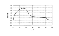
また、図19のグラフは、乱流発生用突条のp/hを変えたランフラットタイヤを用い下記の条件で行った熱伝達率測定試験の結果を示している。グラフの縦軸は、タイヤ表面に貼り付けられた定電圧を印加して一定の熱量を発生させ、ランフラットタイヤを回転させた時のタイヤ表面の温度を測定して求めた熱伝達率である。すなわち、この熱伝達率が大きいということは、冷却効果が高いことを表している。ここでは、乱流発生用突条を形成していないランフラットタイヤの熱伝達率を100に設定している。 Moreover, the graph of FIG. 19 has shown the result of the heat-transfer coefficient measurement test done on condition of the following using the run flat tire which changed p / h of the protrusion for turbulent flow generation | occurrence | production. The vertical axis of the graph represents the heat transfer coefficient obtained by applying a constant voltage applied to the tire surface to generate a certain amount of heat and measuring the temperature of the tire surface when rotating the run-flat tire. . That is, this large heat transfer coefficient indicates that the cooling effect is high. Here, the heat transfer coefficient of the run-flat tire not forming the turbulent flow generation ridge is set to 100.
(熱伝達率測定試験に用いたランフラットタイヤの諸元)
タイヤサイズ:285/50R20
使用リム:8JJ×20
(耐久力試験の条件)
内圧:0kPa
荷重:0.5kN
速度:90km/h
図19のグラフが示すように、p/hは、1.0〜50.0の範囲で熱伝達率が高くなるため、耐久性が高くなっており、2.0〜24.0の範囲ではこれらがさらに向上することを示している。従って、乱流発生用突条は、1.0≦p/h≦50.0の範囲がよく、好ましくは2.0≦p/h≦24.0の範囲、更に好ましくは10.0≦p/h≦20.0の範囲がよいことが分かる。
(Specifications of run-flat tire used for heat transfer coefficient measurement test)
Tire size: 285 / 50R20
Rim used: 8JJ × 20
(Conditions for durability test)
Internal pressure: 0 kPa
Load: 0.5kN
Speed: 90km / h
As shown in the graph of FIG. 19, p / h has high durability because the heat transfer coefficient is high in the range of 1.0 to 50.0, and in the range of 2.0 to 24.0. These show further improvement. Therefore, the ridge for generating turbulent flow preferably has a range of 1.0 ≦ p / h ≦ 50.0, preferably 2.0 ≦ p / h ≦ 24.0, more preferably 10.0 ≦ p. It can be seen that the range of /h≦20.0 is good.
図20のグラフが示すように、(p−w)/wは、1〜100.0の範囲で熱伝達率が高くなるため、耐久性が高くなっており、4.0〜39.0の範囲ではこれらがさらに向上することを示している。従って、乱流発生用突条は、1.0≦(p−w)/w≦100.0の範囲がよく、好ましくは4.0≦(p−w)/w≦39.0の範囲がよいことが分かる。 As the graph of FIG. 20 shows, (p−w) / w has a high heat transfer coefficient in the range of 1 to 100.0, and thus has high durability, which is 4.0 to 39.0. The range shows that these are further improved. Therefore, the ridge for generating turbulent flow preferably has a range of 1.0 ≦ (p−w) /w≦100.0, and preferably has a range of 4.0 ≦ (p−w) /w≦39.0. I know it ’s good.
図21のグラフは、タイヤ径方向に対する乱流発生用突条の延在方向の角度θと熱伝導率との関係を示しており、このグラフによれば、角度θ0°〜70°の範囲で優れた熱伝導率が得られるが、0°〜−70°の範囲でも同様の熱伝達率が得られることが分かる。 The graph of FIG. 21 shows the relationship between the angle θ in the extending direction of the turbulent flow generating ridge with respect to the tire radial direction and the thermal conductivity. According to this graph, the angle θ is in the range of 0 ° to 70 °. Although excellent thermal conductivity is obtained, it can be seen that the same heat transfer coefficient can be obtained in the range of 0 ° to -70 °.
1…ランフラットタイヤ
2…トレッド部
3…タイヤサイド部
4…ビード部
6A…ビードコア
6B…ビードフィラー
7…カーカス層
8…サイド補強層
9,10…スチールベルト補強層
11…周方向補強層
20,21,22,23,24,25,26,27…乱流発生用突条
20a…段差
20b…貫通孔
251,261,262,271,272,273,274,275,276,277,278…エッジ部
DESCRIPTION OF SYMBOLS 1 ... Run
Claims (9)
前記タイヤサイド部の表面は、タイヤサイド部の外面であり、
前記乱流発生用突条の長手方向に対して略直交する幅である突起幅(w)は、前記長手方向で変化しており、
前記長手方向における前記乱流発生用突条の側面である突起側面には、複数の面によりエッジ部が形成されていることを特徴とする空気入りタイヤ。 A pneumatic tire provided with a plurality of turbulent flow generating ridges extending along the tire radial direction on the surface of the tire side portion and formed at intervals along the tire circumferential direction,
The surface of the tire side portion is an outer surface of the tire side portion,
The protrusion width (w), which is a width substantially perpendicular to the longitudinal direction of the turbulent flow generation ridge, is changed in the longitudinal direction ,
A pneumatic tire characterized in that an edge portion is formed by a plurality of surfaces on a side surface of the projection, which is a side surface of the turbulent flow generating ridge in the longitudinal direction .
前記タイヤサイド部の表面から前記乱流発生用突条の最も突出する突出位置までの高さである突起高さを“h”、前記突起幅を“w”、互いに隣接する前記乱流発生用突条同士の間隔を“p”としたときに、1.0≦p/h≦50.0、かつ、1.0≦(p−w)/
w≦100.0の関係を満たすことを特徴とする請求項1乃至請求項6のいずれか1項に記載の空気入りタイヤ。 The plurality of turbulent flow generating ridges are arranged at substantially equal intervals,
The height of the protrusion, which is the height from the surface of the tire side part to the most protruding position of the protrusion for generating turbulent flow, is “h”, the protrusion width is “w”, and the adjacent turbulent flow generating elements When the interval between the protrusions is “p”, 1.0 ≦ p / h ≦ 50.0 and 1.0 ≦ (p−w) /
The pneumatic tire according to any one of claims 1 to 6, characterized in that to satisfy the relation of w ≦ 100.0.
Priority Applications (1)
| Application Number | Priority Date | Filing Date | Title |
|---|---|---|---|
| JP2007198173A JP5242964B2 (en) | 2007-07-30 | 2007-07-30 | Pneumatic tire |
Applications Claiming Priority (1)
| Application Number | Priority Date | Filing Date | Title |
|---|---|---|---|
| JP2007198173A JP5242964B2 (en) | 2007-07-30 | 2007-07-30 | Pneumatic tire |
Publications (2)
| Publication Number | Publication Date |
|---|---|
| JP2009029377A JP2009029377A (en) | 2009-02-12 |
| JP5242964B2 true JP5242964B2 (en) | 2013-07-24 |
Family
ID=40400358
Family Applications (1)
| Application Number | Title | Priority Date | Filing Date |
|---|---|---|---|
| JP2007198173A Active JP5242964B2 (en) | 2007-07-30 | 2007-07-30 | Pneumatic tire |
Country Status (1)
| Country | Link |
|---|---|
| JP (1) | JP5242964B2 (en) |
Families Citing this family (8)
| Publication number | Priority date | Publication date | Assignee | Title |
|---|---|---|---|---|
| JP5251709B2 (en) * | 2009-04-30 | 2013-07-31 | 横浜ゴム株式会社 | Pneumatic tire |
| JP5066240B2 (en) * | 2010-09-24 | 2012-11-07 | 住友ゴム工業株式会社 | Pneumatic tire |
| JP5886532B2 (en) * | 2011-02-25 | 2016-03-16 | 株式会社ブリヂストン | tire |
| JP5986828B2 (en) * | 2012-07-04 | 2016-09-06 | 株式会社ブリヂストン | tire |
| WO2014010297A1 (en) * | 2012-07-11 | 2014-01-16 | 横浜ゴム株式会社 | Pneumatic tire |
| JP6730041B2 (en) * | 2016-02-15 | 2020-07-29 | Toyo Tire株式会社 | Pneumatic tire |
| JP7094073B2 (en) | 2016-02-15 | 2022-07-01 | Toyo Tire株式会社 | Pneumatic tires |
| JP6649109B2 (en) * | 2016-02-15 | 2020-02-19 | Toyo Tire株式会社 | Pneumatic tire |
Family Cites Families (3)
| Publication number | Priority date | Publication date | Assignee | Title |
|---|---|---|---|---|
| JP4417507B2 (en) * | 2000-01-24 | 2010-02-17 | 東洋ゴム工業株式会社 | Pneumatic radial tire |
| JP2006272992A (en) * | 2005-03-28 | 2006-10-12 | Yokohama Rubber Co Ltd:The | Pneumatic tire and its manufacturing method |
| ES2389586T3 (en) * | 2005-09-13 | 2012-10-29 | Bridgestone Corporation | Tire |
-
2007
- 2007-07-30 JP JP2007198173A patent/JP5242964B2/en active Active
Also Published As
| Publication number | Publication date |
|---|---|
| JP2009029377A (en) | 2009-02-12 |
Similar Documents
| Publication | Publication Date | Title |
|---|---|---|
| JP5242964B2 (en) | Pneumatic tire | |
| KR101108289B1 (en) | Pneumatic tire | |
| JP5285698B2 (en) | Pneumatic tire | |
| JP5222551B2 (en) | Pneumatic tire | |
| JP5258210B2 (en) | Pneumatic tire | |
| JP5186203B2 (en) | Pneumatic tire | |
| JP5081476B2 (en) | Pneumatic tire | |
| WO2009133892A1 (en) | Pneumatic tire | |
| JP4980815B2 (en) | Pneumatic tire | |
| JP5956942B2 (en) | tire | |
| JP5007173B2 (en) | Pneumatic tire | |
| JP5478294B2 (en) | Heavy duty tire | |
| JP2009029380A (en) | Pneumatic tire | |
| JP2009029384A (en) | Pneumatic tire | |
| JP2009160991A (en) | Pneumatic tire | |
| JP5406585B2 (en) | Pneumatic tire | |
| JP5243015B2 (en) | Pneumatic tire | |
| JP5147324B2 (en) | Pneumatic tire | |
| JP2010167832A (en) | Pneumatic tire | |
| JP5193593B2 (en) | Pneumatic tire | |
| JP5130003B2 (en) | Pneumatic tire | |
| JP2013018446A (en) | Tire |
Legal Events
| Date | Code | Title | Description |
|---|---|---|---|
| A621 | Written request for application examination |
Free format text: JAPANESE INTERMEDIATE CODE: A621 Effective date: 20100706 |
|
| A131 | Notification of reasons for refusal |
Free format text: JAPANESE INTERMEDIATE CODE: A131 Effective date: 20120321 |
|
| A977 | Report on retrieval |
Free format text: JAPANESE INTERMEDIATE CODE: A971007 Effective date: 20120321 |
|
| A521 | Request for written amendment filed |
Free format text: JAPANESE INTERMEDIATE CODE: A523 Effective date: 20120518 |
|
| A02 | Decision of refusal |
Free format text: JAPANESE INTERMEDIATE CODE: A02 Effective date: 20121127 |
|
| A521 | Request for written amendment filed |
Free format text: JAPANESE INTERMEDIATE CODE: A523 Effective date: 20130225 |
|
| A911 | Transfer to examiner for re-examination before appeal (zenchi) |
Free format text: JAPANESE INTERMEDIATE CODE: A911 Effective date: 20130304 |
|
| TRDD | Decision of grant or rejection written | ||
| A01 | Written decision to grant a patent or to grant a registration (utility model) |
Free format text: JAPANESE INTERMEDIATE CODE: A01 Effective date: 20130402 |
|
| A61 | First payment of annual fees (during grant procedure) |
Free format text: JAPANESE INTERMEDIATE CODE: A61 Effective date: 20130404 |
|
| FPAY | Renewal fee payment (event date is renewal date of database) |
Free format text: PAYMENT UNTIL: 20160412 Year of fee payment: 3 |
|
| R150 | Certificate of patent or registration of utility model |
Free format text: JAPANESE INTERMEDIATE CODE: R150 Ref document number: 5242964 Country of ref document: JP Free format text: JAPANESE INTERMEDIATE CODE: R150 |
|
| R250 | Receipt of annual fees |
Free format text: JAPANESE INTERMEDIATE CODE: R250 |
|
| R250 | Receipt of annual fees |
Free format text: JAPANESE INTERMEDIATE CODE: R250 |
|
| R250 | Receipt of annual fees |
Free format text: JAPANESE INTERMEDIATE CODE: R250 |
|
| R250 | Receipt of annual fees |
Free format text: JAPANESE INTERMEDIATE CODE: R250 |
|
| R250 | Receipt of annual fees |
Free format text: JAPANESE INTERMEDIATE CODE: R250 |
|
| R250 | Receipt of annual fees |
Free format text: JAPANESE INTERMEDIATE CODE: R250 |
|
| R250 | Receipt of annual fees |
Free format text: JAPANESE INTERMEDIATE CODE: R250 |
|
| R250 | Receipt of annual fees |
Free format text: JAPANESE INTERMEDIATE CODE: R250 |