JP5242206B2 - Method for separating and recovering carbon dioxide from blast furnace gas - Google Patents
Method for separating and recovering carbon dioxide from blast furnace gas Download PDFInfo
- Publication number
- JP5242206B2 JP5242206B2 JP2008070121A JP2008070121A JP5242206B2 JP 5242206 B2 JP5242206 B2 JP 5242206B2 JP 2008070121 A JP2008070121 A JP 2008070121A JP 2008070121 A JP2008070121 A JP 2008070121A JP 5242206 B2 JP5242206 B2 JP 5242206B2
- Authority
- JP
- Japan
- Prior art keywords
- carbon dioxide
- blast furnace
- gas
- furnace gas
- absorption
- Prior art date
- Legal status (The legal status is an assumption and is not a legal conclusion. Google has not performed a legal analysis and makes no representation as to the accuracy of the status listed.)
- Expired - Fee Related
Links
- CURLTUGMZLYLDI-UHFFFAOYSA-N Carbon dioxide Chemical compound O=C=O CURLTUGMZLYLDI-UHFFFAOYSA-N 0.000 title claims description 207
- 229910002092 carbon dioxide Inorganic materials 0.000 title claims description 103
- 239000001569 carbon dioxide Substances 0.000 title claims description 102
- 238000000034 method Methods 0.000 title claims description 43
- 238000010521 absorption reaction Methods 0.000 claims description 117
- 239000007788 liquid Substances 0.000 claims description 64
- 238000010438 heat treatment Methods 0.000 claims description 33
- XEEYBQQBJWHFJM-UHFFFAOYSA-N Iron Chemical compound [Fe] XEEYBQQBJWHFJM-UHFFFAOYSA-N 0.000 claims description 18
- 229910052742 iron Inorganic materials 0.000 claims description 9
- 230000008929 regeneration Effects 0.000 claims description 9
- 238000011069 regeneration method Methods 0.000 claims description 9
- 239000000446 fuel Substances 0.000 claims description 7
- 230000006837 decompression Effects 0.000 claims description 5
- OKTJSMMVPCPJKN-UHFFFAOYSA-N Carbon Chemical compound [C] OKTJSMMVPCPJKN-UHFFFAOYSA-N 0.000 claims description 4
- 229910052799 carbon Inorganic materials 0.000 claims description 4
- 238000004519 manufacturing process Methods 0.000 claims 1
- 239000007789 gas Substances 0.000 description 153
- 238000010248 power generation Methods 0.000 description 21
- 239000002737 fuel gas Substances 0.000 description 12
- 238000010586 diagram Methods 0.000 description 11
- 239000000126 substance Substances 0.000 description 11
- 239000000428 dust Substances 0.000 description 9
- 238000002485 combustion reaction Methods 0.000 description 7
- 238000011084 recovery Methods 0.000 description 4
- 239000000571 coke Substances 0.000 description 3
- 230000000694 effects Effects 0.000 description 3
- 230000002745 absorbent Effects 0.000 description 2
- 239000002250 absorbent Substances 0.000 description 2
- 239000006227 byproduct Substances 0.000 description 2
- 238000005516 engineering process Methods 0.000 description 2
- 239000000463 material Substances 0.000 description 2
- 230000001172 regenerating effect Effects 0.000 description 2
- 238000000926 separation method Methods 0.000 description 2
- 230000003584 silencer Effects 0.000 description 2
- 229910000831 Steel Inorganic materials 0.000 description 1
- 150000001412 amines Chemical class 0.000 description 1
- 229910002090 carbon oxide Inorganic materials 0.000 description 1
- 239000000498 cooling water Substances 0.000 description 1
- 230000007423 decrease Effects 0.000 description 1
- 238000002156 mixing Methods 0.000 description 1
- 230000004048 modification Effects 0.000 description 1
- 238000012986 modification Methods 0.000 description 1
- 239000000047 product Substances 0.000 description 1
- 239000002893 slag Substances 0.000 description 1
- 239000004071 soot Substances 0.000 description 1
- 239000010959 steel Substances 0.000 description 1
- 238000009628 steelmaking Methods 0.000 description 1
- 230000009466 transformation Effects 0.000 description 1
- 238000010792 warming Methods 0.000 description 1
- 239000002918 waste heat Substances 0.000 description 1
- 239000002351 wastewater Substances 0.000 description 1
Images


Classifications
-
- Y—GENERAL TAGGING OF NEW TECHNOLOGICAL DEVELOPMENTS; GENERAL TAGGING OF CROSS-SECTIONAL TECHNOLOGIES SPANNING OVER SEVERAL SECTIONS OF THE IPC; TECHNICAL SUBJECTS COVERED BY FORMER USPC CROSS-REFERENCE ART COLLECTIONS [XRACs] AND DIGESTS
- Y02—TECHNOLOGIES OR APPLICATIONS FOR MITIGATION OR ADAPTATION AGAINST CLIMATE CHANGE
- Y02A—TECHNOLOGIES FOR ADAPTATION TO CLIMATE CHANGE
- Y02A50/00—TECHNOLOGIES FOR ADAPTATION TO CLIMATE CHANGE in human health protection, e.g. against extreme weather
- Y02A50/20—Air quality improvement or preservation, e.g. vehicle emission control or emission reduction by using catalytic converters
-
- Y—GENERAL TAGGING OF NEW TECHNOLOGICAL DEVELOPMENTS; GENERAL TAGGING OF CROSS-SECTIONAL TECHNOLOGIES SPANNING OVER SEVERAL SECTIONS OF THE IPC; TECHNICAL SUBJECTS COVERED BY FORMER USPC CROSS-REFERENCE ART COLLECTIONS [XRACs] AND DIGESTS
- Y02—TECHNOLOGIES OR APPLICATIONS FOR MITIGATION OR ADAPTATION AGAINST CLIMATE CHANGE
- Y02C—CAPTURE, STORAGE, SEQUESTRATION OR DISPOSAL OF GREENHOUSE GASES [GHG]
- Y02C20/00—Capture or disposal of greenhouse gases
- Y02C20/40—Capture or disposal of greenhouse gases of CO2
-
- Y—GENERAL TAGGING OF NEW TECHNOLOGICAL DEVELOPMENTS; GENERAL TAGGING OF CROSS-SECTIONAL TECHNOLOGIES SPANNING OVER SEVERAL SECTIONS OF THE IPC; TECHNICAL SUBJECTS COVERED BY FORMER USPC CROSS-REFERENCE ART COLLECTIONS [XRACs] AND DIGESTS
- Y02—TECHNOLOGIES OR APPLICATIONS FOR MITIGATION OR ADAPTATION AGAINST CLIMATE CHANGE
- Y02E—REDUCTION OF GREENHOUSE GAS [GHG] EMISSIONS, RELATED TO ENERGY GENERATION, TRANSMISSION OR DISTRIBUTION
- Y02E20/00—Combustion technologies with mitigation potential
- Y02E20/16—Combined cycle power plant [CCPP], or combined cycle gas turbine [CCGT]
-
- Y—GENERAL TAGGING OF NEW TECHNOLOGICAL DEVELOPMENTS; GENERAL TAGGING OF CROSS-SECTIONAL TECHNOLOGIES SPANNING OVER SEVERAL SECTIONS OF THE IPC; TECHNICAL SUBJECTS COVERED BY FORMER USPC CROSS-REFERENCE ART COLLECTIONS [XRACs] AND DIGESTS
- Y02—TECHNOLOGIES OR APPLICATIONS FOR MITIGATION OR ADAPTATION AGAINST CLIMATE CHANGE
- Y02P—CLIMATE CHANGE MITIGATION TECHNOLOGIES IN THE PRODUCTION OR PROCESSING OF GOODS
- Y02P10/00—Technologies related to metal processing
- Y02P10/10—Reduction of greenhouse gas [GHG] emissions
- Y02P10/122—Reduction of greenhouse gas [GHG] emissions by capturing or storing CO2
-
- Y—GENERAL TAGGING OF NEW TECHNOLOGICAL DEVELOPMENTS; GENERAL TAGGING OF CROSS-SECTIONAL TECHNOLOGIES SPANNING OVER SEVERAL SECTIONS OF THE IPC; TECHNICAL SUBJECTS COVERED BY FORMER USPC CROSS-REFERENCE ART COLLECTIONS [XRACs] AND DIGESTS
- Y02—TECHNOLOGIES OR APPLICATIONS FOR MITIGATION OR ADAPTATION AGAINST CLIMATE CHANGE
- Y02P—CLIMATE CHANGE MITIGATION TECHNOLOGIES IN THE PRODUCTION OR PROCESSING OF GOODS
- Y02P20/00—Technologies relating to chemical industry
- Y02P20/151—Reduction of greenhouse gas [GHG] emissions, e.g. CO2
Landscapes
- Engine Equipment That Uses Special Cycles (AREA)
- Treating Waste Gases (AREA)
- Gas Separation By Absorption (AREA)
- Carbon And Carbon Compounds (AREA)
- Blast Furnaces (AREA)
- Waste-Gas Treatment And Other Accessory Devices For Furnaces (AREA)
Description
本発明は、高炉ガスからの二酸化炭素分離回収方法に関し、外部から熱を供給することなく高炉ガスから効率よく二酸化炭素を分離回収する方法に関する。 The present invention relates to a method for separating and recovering carbon dioxide from blast furnace gas, and to a method for efficiently separating and recovering carbon dioxide from blast furnace gas without supplying heat from the outside.
地球温暖化を防止するため、二酸化炭素の排出削減が重要な課題となっており、二酸化炭素の分離回収方法については、従来から種々の提案がなされている。
例えば、特許文献1には、製鉄所で発生する副生ガスなどから化学吸収法にて二酸化炭素を分離回収する方法であって、当該ガスから化学吸収液で二酸化炭素を吸収後、化学吸収液を加熱し二酸化炭素を分離させるプロセスに製鉄所で発生する低品位排熱を利用または活用することにより、大規模二酸化炭素発生源から排出される二酸化炭素を、コンパクトな設備で効率的かつ安価に分離回収する二酸化炭素の分離回収方法が記載されている。
In order to prevent global warming, reduction of carbon dioxide emissions has become an important issue, and various proposals have been made regarding methods for separating and recovering carbon dioxide.
For example,
この特許文献1は、製鉄所で発生する副生ガス(BFG、COG、LDGなど)から化学吸収法によって、二酸化炭素を分離・回収する方法において、該ガスから化学吸収液で二酸化炭素を吸収後、化学吸収液を加熱し二酸化炭素を分離させるプロセスに製鉄所で発生する例えば、焼結製品クーラーからの排熱(約350℃)、焼結主排気ガス(約280℃)、熱風炉排ガス(約230℃)、焼結主排気ガス(約180℃)、高炉スラグの水砕に用いた排水(約90℃)等の低品位排熱を利用または活用することが開示されている。
また、高炉から排出される高炉ガスは、集塵機によりダストを除去した後において0.2〜0.3MPaの圧力を有することから、TRT(炉頂圧力回収タービン:Top pressure Recovery Turbine)を用いて発電に利用している。その後、製鉄プロセスにおける加熱用及び発電用の燃料ガスとして使用されている。
近年、発電効率を向上させるために、高炉ガスをガスタービン発電装置で燃焼させることにより発電を行う方法が採用されている。このような方法は、例えば特許文献2に開示されている。
This
Moreover, since the blast furnace gas discharged from the blast furnace has a pressure of 0.2 to 0.3 MPa after the dust is removed by the dust collector, power generation is performed using TRT (Top pressure Recovery Turbine). It is used for. After that, it is used as a fuel gas for heating and power generation in the iron making process.
In recent years, in order to improve power generation efficiency, a method of generating power by burning blast furnace gas with a gas turbine power generator has been adopted. Such a method is disclosed in
図5を用いて、前記従来技術の概要を説明する。図5は高炉ガスを燃料とする焚ガスタービン発電装置の系統図である。高炉ガスA(BFG)は、図示しない高炉から発生したものであり、ダストキャッチャ1、第1ベンチュリースクラバ2、第2ベンチュリースクラバ3、乾式集塵装置4からなる各種集塵装置により清浄化された後、TRT5または減圧弁(4)6およびサンレンサー7からなる高炉ガスの減圧手段により、大気圧近くまで降圧された後、ガスホルダ8に貯えられる。前記BFGをガスタービン発電装置用燃料として使用するときは図示していないコークス炉ガス(COG)等と混合されてガスタービン燃焼に必要な熱量まで増燃され、燃料ガス圧縮機9-1によって圧縮される。圧縮された前記燃料ガスは、空気圧縮機9-5を出た圧縮空気と燃焼器9-2内で混合され燃焼して、ガスタービン9-3を駆動し排気ガスとなって、更に蒸気ボイラ9-4で蒸気を生成し、蒸気タービン9-7の動力源となる。なお符号9-6は発電機、符号9-8は復水器をそれぞれ示す。
The outline of the prior art will be described with reference to FIG. FIG. 5 is a system diagram of a soot gas turbine power generator using blast furnace gas as fuel. Blast furnace gas A (BFG) is generated from a blast furnace (not shown) and cleaned by various dust collectors including a
しかし、前記特許文献1では、に開示されている化学吸収液で二酸化炭素を吸収後、化学吸収液を加熱し二酸化炭素を分離させるプロセスに製鉄所で発生する低品位排熱を利用または活用する技術では、以下の課題を有しており実用技術として利用することができない。
高炉から排出される高炉ガスの排出量は、極めて多量であるため、その処理量が多量となる。よって、前記のプロセスにおいて、多量の二酸化炭素を吸収した吸収液を加熱・再生するために、前記製鉄所で発生する低品位排熱を利用する方法では、全く、その加熱エネルギが著しく不足する。よって、前記多量の高炉ガスを処理するには、吸収液を加熱・再生するための新たな加熱手段を配置する必要があり、実用技術としての実現性が難しい。
一方、前記特許文献2では、ガス中の二酸化炭素の吸収・分離については、一切開示がない。よって、高炉ガス燃焼後のガスタービンからの排ガス中に含まれている二酸化炭素を処理することができない。
However, in
Since the amount of blast furnace gas discharged from the blast furnace is extremely large, the amount of treatment becomes large. Therefore, in the process described above, the method of using the low-grade exhaust heat generated at the steelworks to heat and regenerate the absorbing solution that has absorbed a large amount of carbon dioxide has a very short heating energy. Therefore, in order to process the large amount of blast furnace gas, it is necessary to arrange a new heating means for heating and regenerating the absorbing liquid, and it is difficult to realize it as a practical technique.
On the other hand, in
本発明の目的は、前述のような従来技術の課題を解決し、前記発電効率を向上させるため、清浄化された高炉ガスをガスタービン発電装置で燃焼させることにより発電を行う方法において、高炉ガス中及びまたは高炉ガス燃焼後のガスタービンからの排ガス中に含まれている多量の二酸化炭素を吸収した吸収液を加熱・再生するための新たな加熱手段を配置することなく分離回収することができる高炉ガスからの二酸化炭素分離回収方法を提供することにある。 An object of the present invention is to solve the above-described problems of the prior art and improve the power generation efficiency, in a method of generating power by burning a cleaned blast furnace gas in a gas turbine power generator, It can be separated and recovered without arranging new heating means to heat and regenerate the absorbing liquid that has absorbed a large amount of carbon dioxide contained in the exhaust gas from the gas turbine after the middle and / or blast furnace gas combustion The object is to provide a method for separating and recovering carbon dioxide from blast furnace gas.
本発明の高炉ガスからの二酸化炭素分離回収方法は、高炉から取り出された高炉ガスを吸収塔に導入し、前記吸収塔内で前記吸収液に前記高炉ガス中の二酸化炭素を吸収させ、前記二酸化炭素を除去された前記高炉ガスの一部を製鉄プロセスで燃焼させて熱源として利用し、前記二酸化炭素を除去された前記高炉ガスの他の一部はガスタービン発電装置に導入して燃焼させて発電を行う燃料として利用し、前記吸収塔で前記二酸化炭素を吸収した吸収液を前記ガスタービンの排ガスの熱で加熱し、加熱された前記吸収液を再生塔へ導入し、前記再生塔内で前記吸収液から前記二酸化炭素を除去し、前記二酸化炭素を除去された前記吸収液を前記吸収塔へと循環させることを特徴とする。 In the method for separating and recovering carbon dioxide from blast furnace gas according to the present invention, the blast furnace gas taken out from the blast furnace is introduced into an absorption tower, and the carbon dioxide in the blast furnace gas is absorbed by the absorption liquid in the absorption tower, and the carbon dioxide. A part of the blast furnace gas from which carbon has been removed is burned in a steel making process and used as a heat source, and another part of the blast furnace gas from which the carbon dioxide has been removed is introduced into a gas turbine power generator and burned. The absorption liquid that is used as a fuel for power generation and has absorbed the carbon dioxide in the absorption tower is heated by the heat of the exhaust gas of the gas turbine, and the heated absorption liquid is introduced into the regeneration tower, The carbon dioxide is removed from the absorption liquid, and the absorption liquid from which the carbon dioxide has been removed is circulated to the absorption tower.
このような本発明においては、高炉からの高炉ガスは吸収塔において二酸化炭素を除去されたうえ、製鉄プロセスの加熱用燃料として利用されるとともに、ガスタービン発電装置の燃料として発電に利用される。更に、ガスタービンからの排ガスは、その熱を先の吸収塔で二酸化炭素除去に用いた吸収液の再生に利用される。従って、二酸化炭素の分離回収を効率よく行うことができる。また、高炉ガス中の不燃成分である二酸化炭素を除去するため、燃料ガスとしての熱量が高くなり、COG等の増燃材の添加量を削減することができる。 In the present invention, the blast furnace gas from the blast furnace is used for power generation as a fuel for a gas turbine power generation device while carbon dioxide is removed in an absorption tower and is used as a heating fuel in an iron making process. Further, the exhaust gas from the gas turbine is used to regenerate the absorption liquid used for removing carbon dioxide in the previous absorption tower. Therefore, carbon dioxide can be separated and recovered efficiently. Further, since carbon dioxide, which is an incombustible component in the blast furnace gas, is removed, the amount of heat as fuel gas is increased, and the amount of addition of a fuel increasing material such as COG can be reduced.
本発明の高炉ガスからの二酸化炭素分離回収方法において、前記吸収塔を前記高炉ガスの減圧手段の前段に設置し、前記高炉ガスを高圧の状態で前記吸収塔に導入することが望ましい。
このような本発明では、吸収塔においては高炉ガスを減圧前の高い圧力とすることができ、吸収液への二酸化炭素の吸収性能を高く維持することができる。
In the method for separating and recovering carbon dioxide from blast furnace gas according to the present invention, it is preferable that the absorption tower is installed in front of the blast furnace gas decompression means, and the blast furnace gas is introduced into the absorption tower in a high pressure state.
In such an invention, in the absorption tower, the blast furnace gas can be set to a high pressure before depressurization, and the absorption performance of carbon dioxide into the absorption liquid can be maintained high.
本発明の高炉ガスからの二酸化炭素分離回収方法において、前記ガスタービン発電装置の排ガスを副吸収塔に導入し、前記副吸収塔内で前記吸収液に前記排ガス中の二酸化炭素を吸収させることが望ましい。
このような本発明においては、高炉からの高炉ガスに含まれる二酸化炭素は前述した吸収塔で吸収されるとともに、その後にガスタービン発電装置で高炉ガスが燃焼することで発生する二酸化炭素は副吸収塔で吸収することができ、二酸化炭素の分離回収量を増加させつつ吸収液の循環による効率的な運用を行うことができる。
In the method for separating and recovering carbon dioxide from blast furnace gas according to the present invention, the exhaust gas of the gas turbine power generator is introduced into a sub-absorption tower, and the absorption liquid absorbs carbon dioxide in the exhaust gas in the sub-absorption tower. desirable.
In the present invention, carbon dioxide contained in the blast furnace gas from the blast furnace is absorbed by the absorption tower described above, and carbon dioxide generated by the subsequent combustion of the blast furnace gas in the gas turbine power generator is sub-absorbed. It can be absorbed by the tower and can be efficiently operated by circulating the absorption liquid while increasing the amount of carbon dioxide separated and recovered.
本発明の高炉ガスからの二酸化炭素分離回収方法において、前記吸収液の加熱に必要な熱量が前記ガスタービンの排ガスの持つ熱量と比較して著しく少ない場合は、前記ガスタービン発電装置として、前記ガスタービンの排ガスの熱の一部を利用して高圧蒸気を発生する蒸気ボイラと、この蒸気ボイラからの高圧蒸気を前記ガスタービン発電装置の動力として利用する蒸気タービンと、この蒸気タービンからの利用済蒸気を復水する復水器とを有する装置を用い、前記吸収液の加熱には前記ガスタービン排ガスの熱の一部と前記復水器での復水熱を利用することが望ましい。
このような本発明においては、ガスタービン発電装置の従来捨てていた復水熱を前記吸収液の加熱に利用するので、ガスタービン発電装置で前記高炉ガスの燃焼により発生する熱の利用効率が向上する。
In the method for separating and recovering carbon dioxide from blast furnace gas according to the present invention, when the amount of heat necessary for heating the absorption liquid is significantly smaller than the amount of heat of the exhaust gas of the gas turbine, the gas turbine power generator A steam boiler that generates high-pressure steam using a part of the heat of the exhaust gas from the turbine, a steam turbine that uses high-pressure steam from the steam boiler as power for the gas turbine power generation device, and a used steam turbine It is desirable to use a device having a condenser for condensing steam, and use the heat of the gas turbine exhaust gas and the condensate heat in the condenser for heating the absorption liquid.
In the present invention, since the condensate heat that has been discarded by the gas turbine power generation device is used for heating the absorption liquid, the efficiency of use of heat generated by the combustion of the blast furnace gas in the gas turbine power generation device is improved. To do.
以下、本発明の好適な実施形態について図面を用いて詳細に説明する。
[第1実施形態]
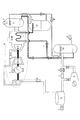
図1Aには、本発明の第1実施形態が示されている。
図1Aにおいて、5はTRT(炉頂圧回収タービン)、6は減圧弁、7はサイレンサであり、以上により高炉ガスの減圧手段が構成されている。
8はガスホルダ、9−1は燃料ガス圧縮機、9−2は燃焼器、9−3はガスタービン、9−4A…二酸化炭素吸収液加熱用熱交換器、9−5は空気圧縮機、9−6は発電機を各々示す。
DESCRIPTION OF EMBODIMENTS Hereinafter, preferred embodiments of the present invention will be described in detail with reference to the drawings.
[First Embodiment]
FIG. 1A shows a first embodiment of the present invention.
In FIG. 1A, 5 is a TRT (furnace top pressure recovery turbine), 6 is a pressure reducing valve, 7 is a silencer, and the pressure reducing means for the blast furnace gas is configured as described above.
8 is a gas holder, 9-1 is a fuel gas compressor, 9-2 is a combustor, 9-3 is a gas turbine, 9-4A ... a heat exchanger for heating carbon dioxide absorption liquid, 9-5 is an air compressor, 9 -6 shows each generator.
9のガスタービン発電装置は、前記燃料ガス圧縮機9−1、燃焼器9−2、ガスタービン9−3、二酸化炭素吸収液加熱用熱交換器9−4A、空気圧縮機9−5、発電機9−6で構成されている。また、10は吸収塔、12は再生塔を示す。
図中、矢印Bは、前記従来技術の項で説明した各種集塵装置(図示省略)により清浄化された高圧清浄高炉ガスであり、一部はラインCへと分岐され、他の一部はラインE,Fを経て矢印Gへ排出される。一方、矢印L,Mで示す流れは、二酸化炭素の吸収液の循環流れを示す。矢印Kは分離された二酸化炭素である。
なお、以後の各実施形態において、同じ要素については同じ記号を用いることにより説明の重複を避ける。
9 includes a fuel gas compressor 9-1, a combustor 9-2, a gas turbine 9-3, a heat exchanger 9-4A for heating carbon dioxide absorption liquid, an air compressor 9-5, and power generation. Machine 9-6.
In the figure, the arrow B is the high-pressure clean blast furnace gas cleaned by the various dust collectors (not shown) described in the section of the prior art, part of which is branched to the line C and the other part is It is discharged to an arrow G via lines E and F. On the other hand, the flow indicated by arrows L and M indicates the circulation flow of the carbon dioxide absorption liquid. Arrow K is the separated carbon dioxide.
In the following embodiments, the same symbols are used for the same elements to avoid duplication of explanation.
本発明に適用する二酸化炭素の分離吸収法としては、例えば化学吸収法を用いて、アミン類などの化学吸収液を用いる。
高炉から取り出され清浄化された高圧清浄高炉ガスBは、前記高炉ガスの減圧手段の前段に設置している吸収塔10に導入される。該吸収塔10内では、該高炉ガスを、二酸化炭素吸収媒体である化学吸収液に50℃前後で接触させ、化学吸収液に前記高炉ガス中の二酸化炭素が吸収される。
その後、前記二酸化炭素が除去された前記高炉ガスの一部は、ガスホルダ8を経て、例えば、図示していないコークス炉、加熱炉などに搬送され各種の製鉄プロセスで燃焼させて熱源として利用される。
As the carbon dioxide separation and absorption method applied to the present invention, for example, a chemical absorption method is used, and a chemical absorption solution such as amines is used.
The high-pressure clean blast furnace gas B taken out from the blast furnace and purified is introduced into the
Thereafter, a part of the blast furnace gas from which the carbon dioxide has been removed passes through the
他方、前記二酸化炭素を除去された前記高炉ガスの他の一部は燃料ガス圧縮機9−1によって圧縮される。圧縮された前記燃料ガスは、空気圧縮機9−5を出た圧縮空気と燃焼器9−2内で混合・燃焼して、ガスタービン9−3を駆動し、排気ガスは二酸化炭素吸収液加熱用熱交換器9−4Aを経て煙突から大気中に放出される。
この際、前記吸収塔10で前記二酸化炭素を吸収した吸収液は、前記ガスタービン9−3の排ガスの熱で、二酸化炭素吸収液加熱用熱交換器9−4Aにて120℃前後に加熱され、その後、再生塔12にて吸収液から二酸化炭素を分離回収し、再生された吸収液は戻り配管を通じて吸収塔10に戻すことで、吸収液は吸収塔10と再生塔12の間を循環して循環利用することができる。
On the other hand, the other part of the blast furnace gas from which the carbon dioxide has been removed is compressed by the fuel gas compressor 9-1. The compressed fuel gas is mixed and burned in the combustor 9-2 with the compressed air exiting the air compressor 9-5 to drive the gas turbine 9-3, and the exhaust gas is heated by the carbon dioxide absorption liquid. It is discharged | emitted from the chimney in air | atmosphere through the heat exchanger 9-4A.
At this time, the absorption liquid that has absorbed the carbon dioxide in the
前記のとおり、ガスタービン発電装置9からの排ガスは、その熱を先の吸収塔で二酸化炭素除去に用いた吸収液の再生に利用される。従って、新たな加熱手段を設けることなく、二酸化炭素の分離回収を効率よく、且つ多量の高炉ガスの処理が可能となる。
ガスタービン9−3からの排ガス全熱量は、前記酸化炭素吸収液加熱用熱交換器9−4Aにて全て、二酸化炭素吸収液加熱用として使用されるため、従来のように、図5の蒸気タービン9−7を設置する必要がなく、簡素な設備構成でエネルギを有効に活用することが可能である。また、高炉ガス中の不燃成分である二酸化炭素を除去するため、燃料ガスとしての熱量が高くなり、COG等の増燃材の添加量を削減することができる
As described above, the exhaust gas from the gas turbine
Since the total heat quantity of the exhaust gas from the gas turbine 9-3 is used for heating the carbon dioxide absorption liquid in the heat exchanger 9-4A for heating the carbon oxide absorption liquid, the steam shown in FIG. It is not necessary to install the turbine 9-7, and energy can be effectively used with a simple equipment configuration. In addition, because carbon dioxide, which is an incombustible component in blast furnace gas, is removed, the amount of heat as fuel gas increases, and the amount of additional fuel-enhancing materials such as COG can be reduced
また、前記のとおり、分離回収された二酸化炭素は、例えば、圧縮処理され超臨界状態で地中に圧入されるので、大気中に排出される二酸化炭素を大幅に削減することができる。
さらに、吸収塔10の配設位置を高炉ガスの各種集塵装置の後段にしているため、該高炉ガスは、清浄化されたものであり吸収液が劣化することがない。
さらに、吸収塔10を前記高炉ガスの減圧手段の前段に設置し、前記高炉ガスを高圧の状態で前記吸収塔10に導入している。よって、本発明では、吸収塔において、高炉ガスを減圧前の高い圧力とすることができ、吸収液への二酸化炭素の吸収性能を高く維持することができる。
Further, as described above, the carbon dioxide separated and recovered is, for example, compressed and injected into the ground in a supercritical state, so that carbon dioxide discharged into the atmosphere can be greatly reduced.
Further, since the position of the
Furthermore, the
[第2実施形態]
図2Aには本発明の第2実施形態が示されている。
図2Aにおいて、本実施形態の前記第1実施形態に対するその構成上の相違点は、吸収塔10を前記高炉ガスの減圧手段(炉頂圧回収タービン5および減圧弁6)の後段に設置していることである。その他の構成は、前記図1Aと同じ構成であるので、重複する説明は省略する。
このような、図2Aの構成によっても、前記図1Aと同様の効果が得られる。但し、吸収塔10を前記高炉ガスの減圧手段の後段になるため、吸収性能は前記第1実施形態にはおよばない。
[Second Embodiment]
FIG. 2A shows a second embodiment of the present invention.
In FIG. 2A, the structural difference of the present embodiment from the first embodiment is that the
Such a configuration of FIG. 2A also provides the same effect as in FIG. 1A. However, since the
[第3実施形態]
図1Bには本発明の第3実施形態が示されている。
図1Bにおいて、その構成は前記図1Aで説明した構成に加え、二酸化炭素吸収液加熱用熱交換器9−4Aの後段に、新たに副吸収塔11を設けた点である。
その他の構成は、前記図1Aと同じ構成であるので、重複する説明は省略する。
前記ガスタービン発電装置9の排ガスは、前記副吸収塔11にて、吸収液と接触し、排ガス中から、二酸化炭素が除去された後、系外に排出される。
一方、二酸化炭素を吸収した吸収液は、前記吸収塔10での二酸化炭素を吸収した吸収液と合流され、その後、前記ガスタービンの排ガスの熱で、二酸化炭素吸収液加熱用熱交換器9−4Aにて120℃前後に加熱し、再生塔12にて化学吸収液から二酸化炭素を分離回収される。
[Third Embodiment]
FIG. 1B shows a third embodiment of the present invention.
In FIG. 1B, in addition to the configuration described in FIG. 1A, the configuration is that a
The other configuration is the same as that shown in FIG.
The exhaust gas from the gas turbine
On the other hand, the absorption liquid that has absorbed carbon dioxide is merged with the absorption liquid that has absorbed carbon dioxide in the
[第4実施形態]
図6には、本発明の第4実施形態が示されている。
図6において、その構成は前記図1Bで説明した構成に加え、前記製鉄プロセスの排ガスNを前記二酸化炭素吸収液加熱用熱交換器9−4Aに導入して、前記ガスタービン発電装置9の排ガスと合流させた点である。その他の点は前記図1Bと同じ構成であるので、重複する説明は省略する。
製鉄プロセスの排ガスLはガスタービン発電装置9の排ガスとともに副吸収塔11にて、吸収液と接触し、排ガス中から、二酸化炭素が除去された後、形骸に排出される。また、前記ガスタービンからの排ガスと前記製鉄プロセスからの排ガスを混合することにより、前記二酸化炭素吸収液加熱用熱交換器でのガス温度が下がり、二酸化炭素吸収液が過熱され、劣化することを防止できる。
[Fourth Embodiment]
FIG. 6 shows a fourth embodiment of the present invention.
In FIG. 6, in addition to the configuration described in FIG. 1B, the exhaust gas N of the iron making process is introduced into the carbon dioxide absorbent heating heat exchanger 9-4 </ b> A, and the exhaust gas of the gas turbine
The exhaust gas L of the iron making process is brought into contact with the absorbing liquid in the
[第5実施形態]
図2Bには本発明の第5実施形態が示されている。
図2Bにおいて、その構成は吸収塔10を前記高炉ガスの減圧手段の後段に設置している。その他の構成は、前記図1Bと同じ構成であるので、重複する説明は省略する。
このような、図2Bの構成によっても、前記図1Bと同様の効果が得られる。但し、吸収塔10を前記高炉ガスの減圧手段の後段になるため、吸収性能は前記第1実施形態にはおよばない。
[Fifth Embodiment]
FIG. 2B shows a fifth embodiment of the present invention.
In FIG. 2B, the structure has installed the
Such a configuration of FIG. 2B also provides the same effect as in FIG. 1B. However, since the
[第6実施形態]
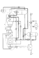
図3Aには本発明の第6実施形態が示されている。
図3Aにおいて、9−4蒸気ボイラ、9−7は蒸気タービン、9−8は前記蒸気タービン9−7からの利用済蒸気を復水する復水器を示す。蒸気ボイラ13内には、二つの熱交換管路が設けられている。前記ガスタービン9−3の排ガスの熱で、一方は高圧蒸気Iを発生させ、前記蒸気タービン9−7を駆動させ、発電するものであり、他方は、吸収塔10で、高炉ガス中の二酸化炭素を吸着した吸収液Lから二酸化炭素分離するために前記二酸化炭素を吸着した二酸化炭素吸収液Lを加熱するための熱交換管路である。
[Sixth Embodiment]
FIG. 3A shows a sixth embodiment of the present invention.
In FIG. 3A, 9-4 steam boiler, 9-7 is a steam turbine, 9-8 shows the condenser which condenses the used steam from the said steam turbine 9-7. Two heat exchange pipes are provided in the steam boiler 13. The heat of the exhaust gas from the gas turbine 9-3 generates one of the high-pressure steam I, drives the steam turbine 9-7 to generate electric power, and the other is the
かかる構成を有する高炉ガスからの二酸化炭素分離回収方法の適用方法は、前記吸収液の加熱に必要な熱量が前記ガスタービン9−7の排ガスの持つ熱量と比較して著しく少ない場合に実施すると好ましい。
即ち、前記ガスタービン発電装置9として、前記ガスタービン9−3の排ガスの熱の一部を利用して高圧蒸気を発生する蒸気ボイラ9−4と、この蒸気ボイラからの高圧蒸気を前記ガスタービン発電装置9の動力として利用する蒸気タービン9−7と、この蒸気タービン9−7からの利用済蒸気を復水する復水器9−8とを有する装置を用い、前記吸収液の加熱には前記ガスタービン9−3の排ガスの熱の一部と前記復水器9−8での復水熱を利用することが望ましい。
このような本発明においては、ガスタービン発電装置9を構成する復水器9−8における従来捨てていた復水熱を前記吸収液の加熱に利用するので、ガスタービン発電装置9で前記高炉ガスの燃焼により発生する熱の利用効率が向上する。
The method of applying the method for separating and recovering carbon dioxide from blast furnace gas having such a configuration is preferably performed when the amount of heat necessary for heating the absorption liquid is significantly less than the amount of heat of the exhaust gas of the gas turbine 9-7. .
That is, as the gas turbine
In the present invention, since the condensate heat previously discarded in the condenser 9-8 constituting the gas turbine
[第7実施形態]
図3Bには本発明の第7実施形態が示されている。
図3Bにおいて、その構成は前記図3Aで説明した構成に加え、二酸化炭素吸収液加熱用熱交換器9−4Aの後段に、副吸収塔11を設けている。
その他の構成は、前記図1Aと同じ構成であるので、重複する説明は省略する。
前記ガスタービン発電装置9の排ガスは、前記副吸収塔11にて、吸収液と接触し、排ガス中から、二酸化炭素が除去された後、系外に排出される。
一方、二酸化炭素を吸収した吸収液は、前記吸収塔10での二酸化炭素を吸収した吸収液と合流され、その後、前記ガスタービン9−3の排ガスの熱で、二酸化炭素吸収液加熱用熱交換器9−4Aにて120℃前後に加熱し、再生塔12にて吸収液から二酸化炭素を分離回収される。
[Seventh Embodiment]
FIG. 3B shows a seventh embodiment of the present invention.
In FIG. 3B, in addition to the configuration described in FIG. 3A, the
The other configuration is the same as that shown in FIG.
The exhaust gas from the gas turbine
On the other hand, the absorption liquid that has absorbed carbon dioxide is merged with the absorption liquid that has absorbed carbon dioxide in the
[第8実施形態]
図4Aには本発明の第8実施形態が示されている。
図4Aにおいて、その構成は、前記図3Aで説明した構成において、吸収塔10を高炉ガスの減圧手段の後段に配設している。
その他の構成は、前記図1Aと同じ構成であるので、重複する説明は省略する。
[Eighth Embodiment]
FIG. 4A shows an eighth embodiment of the present invention.
In FIG. 4A, the structure is the structure demonstrated in the said FIG. 3A, and the
The other configuration is the same as that shown in FIG.
[第9実施形態]
図4Bには本発明の第9実施形態が示されている。
図4Bにおいて、その構成は、前記図4Aで説明した構成に加え、二酸化炭素吸収液加熱用熱交換器9−4Aの後段に、新たに副吸収塔11を設けた点である。
その他の構成は、前記図4Aと同じ構成であるので、重複する説明は省略する。
[Ninth Embodiment]
FIG. 4B shows a ninth embodiment of the present invention.
In FIG. 4B, the configuration is that, in addition to the configuration described in FIG. 4A, a
The other configuration is the same as that shown in FIG.
[変形例]
なお、本発明は前記実施形態の構成に限定されるものではなく、本発明の目的を達成しようとする範囲内の変形等は本発明に含まれるものである。
前記図1B、図2B、図3B、図4Bの実施形態において、副吸収塔11にて二酸化炭素を吸着した吸収液と、吸収塔10にて二酸化炭素を吸着した吸収液とを一旦、合流後、二酸化炭素吸収液加熱用熱交換器9−4Aに搬送しているが、本発明は、これに限られることなく、前記各々の吸収塔から、個別に二酸化炭素吸収液加熱用熱交換器9−4Aに搬送しても同様な効果を奏する。
[Modification]
In addition, this invention is not limited to the structure of the said embodiment, The deformation | transformation etc. in the range which intends to achieve the objective of this invention are included in this invention.
1B, FIG. 2B, FIG. 3B, and FIG. 4B, after the merging of the absorption liquid that adsorbs carbon dioxide in the
本発明の高炉ガスからの二酸化炭素分離回収方法は、清浄化された高炉ガスをガスタービン発電装置で燃焼させることにより発電を行う工程、高炉ガス中及びまたは高炉ガス燃焼後のガスタービンからの排ガス中に含まれている多量の二酸化炭素を吸収した吸収液を加熱・再生する工程として利用できる。 The method for separating and recovering carbon dioxide from blast furnace gas according to the present invention includes a step of generating power by burning purified blast furnace gas in a gas turbine power generator, exhaust gas from blast furnace gas and / or gas turbine after blast furnace gas combustion. It can be used as a process for heating and regenerating an absorbing solution that has absorbed a large amount of carbon dioxide contained therein.
1…ダストキャッチャ
2…第1ベンチュリースクラバ
3…第2ベンチュリースクラバ
4…乾式集塵装置
5…TRT(炉頂圧回収タービン)
6…減圧弁
7…サイレンサ
8…ガスホルダ
9…ガスタービン発電装置
9−1…燃料ガス圧縮機
9−2…燃焼器
9−3…ガスタービン
9−4…蒸気ボイラ
9−4A…二酸化炭素吸収液加熱用熱交換器
9−5…空気圧縮機
9−6…発電機
9−7…蒸気タービン
9−8…復水器
10…吸収塔
11…副吸収塔
12…再生塔
A…高炉ガス
B…高圧清浄高炉ガス
C…製鉄プロセスの加熱用燃料ガス
D…コークス炉ガス
E…ガスタービン発電装置用燃料ガス
F…空気
G…排ガス
H…冷却水
I…蒸気
J…オフガス
K…二酸化炭素
L…二酸化炭素を吸着した二酸化炭素吸収液
M…二酸化炭素を吸着する前の二酸化炭素吸収液
N…製鉄プロセスからの排ガス
DESCRIPTION OF
DESCRIPTION OF
Claims (4)
前記吸収塔を前記高炉ガスの減圧手段の前段に設置し、前記高炉ガスを高圧の状態で前記吸収塔に導入することを特徴とする高炉ガスからの二酸化炭素分離回収方法。 The method for separating and recovering carbon dioxide from blast furnace gas according to claim 1,
A method for separating and recovering carbon dioxide from blast furnace gas, wherein the absorption tower is installed in front of the blast furnace gas decompression means, and the blast furnace gas is introduced into the absorption tower in a high pressure state.
前記ガスタービン発電装置の排ガスを副吸収塔に導入し、前記副吸収塔内で前記吸収液に前記排ガス中の二酸化炭素を吸収させることを特徴とする高炉ガスからの二酸化炭素分離回収方法。 In the method for separating and recovering carbon dioxide from blast furnace gas according to claim 1 or 2,
A method for separating and recovering carbon dioxide from blast furnace gas, wherein exhaust gas from the gas turbine power generator is introduced into a sub-absorption tower, and carbon dioxide in the exhaust gas is absorbed into the absorption liquid in the sub-absorption tower.
前記ガスタービン発電装置として、ガスタービンの排ガスの熱を利用して高圧蒸気を発生する蒸気ボイラと、この蒸気ボイラからの高圧蒸気を前記ガスタービン発電装置の動力として利用する蒸気タービンと、この蒸気タービンからの利用済蒸気を復水する復水器とを有する装置を用い、前記ガスタービンの排ガスの熱の一部と前記復水器の熱を前記吸収液の加熱に利用することを特徴とする高炉ガスからの二酸化炭素分離回収方法。 In the method for separating and recovering carbon dioxide from blast furnace gas according to any one of claims 1 to 3,
As the gas turbine power generator, a steam boiler that generates high-pressure steam using the heat of exhaust gas from the gas turbine, a steam turbine that uses high-pressure steam from the steam boiler as power for the gas turbine power generator, and the steam Using a device having a condenser for condensing used steam from a turbine, and utilizing a part of the heat of the exhaust gas of the gas turbine and the heat of the condenser for heating the absorption liquid, To separate and recover carbon dioxide from blast furnace gas.
Priority Applications (1)
| Application Number | Priority Date | Filing Date | Title |
|---|---|---|---|
| JP2008070121A JP5242206B2 (en) | 2008-03-18 | 2008-03-18 | Method for separating and recovering carbon dioxide from blast furnace gas |
Applications Claiming Priority (1)
| Application Number | Priority Date | Filing Date | Title |
|---|---|---|---|
| JP2008070121A JP5242206B2 (en) | 2008-03-18 | 2008-03-18 | Method for separating and recovering carbon dioxide from blast furnace gas |
Publications (2)
| Publication Number | Publication Date |
|---|---|
| JP2009221574A JP2009221574A (en) | 2009-10-01 |
| JP5242206B2 true JP5242206B2 (en) | 2013-07-24 |
Family
ID=41238646
Family Applications (1)
| Application Number | Title | Priority Date | Filing Date |
|---|---|---|---|
| JP2008070121A Expired - Fee Related JP5242206B2 (en) | 2008-03-18 | 2008-03-18 | Method for separating and recovering carbon dioxide from blast furnace gas |
Country Status (1)
| Country | Link |
|---|---|
| JP (1) | JP5242206B2 (en) |
Families Citing this family (5)
| Publication number | Priority date | Publication date | Assignee | Title |
|---|---|---|---|---|
| AT507525B1 (en) * | 2008-10-23 | 2010-09-15 | Siemens Vai Metals Tech Gmbh | METHOD AND DEVICE FOR OPERATING A MELT REDUCTION PROCESS |
| CN102341508B (en) * | 2009-09-30 | 2013-12-25 | 新日铁工程技术株式会社 | Method for separating and collecting carbon dioxide from blast furnace gas |
| JP5638262B2 (en) | 2010-02-23 | 2014-12-10 | 三菱重工業株式会社 | CO2 recovery apparatus and CO2 recovery method |
| KR101304886B1 (en) | 2010-11-30 | 2013-09-06 | 기아자동차주식회사 | System for regenerating CO2 absorption solution |
| JP2024070639A (en) * | 2022-11-11 | 2024-05-23 | 三菱重工業株式会社 | Carbon dioxide recovery system |
Family Cites Families (6)
| Publication number | Priority date | Publication date | Assignee | Title |
|---|---|---|---|---|
| JPS60147539A (en) * | 1984-01-11 | 1985-08-03 | Ube Ind Ltd | Gas-turbine power plant utilizing blast-furnace gas as fuel |
| JPH01201017A (en) * | 1988-02-05 | 1989-08-14 | Nippon Steel Corp | Recovery of byproduct gas generated in ironworks |
| JPH01230416A (en) * | 1988-03-11 | 1989-09-13 | Nkk Corp | Recovery of carbon dioxide from blast-furnace gas |
| JP3814206B2 (en) * | 2002-01-31 | 2006-08-23 | 三菱重工業株式会社 | Waste heat utilization method of carbon dioxide recovery process |
| JP2005195283A (en) * | 2004-01-08 | 2005-07-21 | Nippon Steel Corp | Method of absorbing co2 in by-product gas using waste heat of circulating refrigerant of stave cooler |
| JP5184061B2 (en) * | 2007-11-22 | 2013-04-17 | 新日鉄住金エンジニアリング株式会社 | Method for separating and recovering carbon dioxide from blast furnace gas |
-
2008
- 2008-03-18 JP JP2008070121A patent/JP5242206B2/en not_active Expired - Fee Related
Also Published As
| Publication number | Publication date |
|---|---|
| JP2009221574A (en) | 2009-10-01 |
Similar Documents
| Publication | Publication Date | Title |
|---|---|---|
| JP5242207B2 (en) | Method for separating and recovering carbon dioxide from blast furnace gas in blast furnace gas utilization process | |
| JP5021917B2 (en) | CO2 recovery apparatus and method | |
| JP5184061B2 (en) | Method for separating and recovering carbon dioxide from blast furnace gas | |
| US8752384B2 (en) | Carbon dioxide capture interface and power generation facility | |
| EP2043764A1 (en) | Co2 capture using solar thermal energy | |
| JP2013533426A (en) | Jet engine with carbon capture | |
| JPH03193116A (en) | Removal of co2 combustion exhaust gas | |
| CA2490429A1 (en) | Low emission thermal plant | |
| JP5242206B2 (en) | Method for separating and recovering carbon dioxide from blast furnace gas | |
| JP2012192403A (en) | Co2 recovery apparatus | |
| KR102021983B1 (en) | Integrated condenser capable of recovering latent heat and removing pollutants of exhaust gas and power generation system using pressurized oxygen combustion comprising the same | |
| JPWO2011108086A1 (en) | Exhaust gas treatment system with carbon dioxide removal device | |
| JP2011194292A (en) | Method and apparatus for treating exhaust gas | |
| JP2012091083A (en) | Thermal power plant equipped with carbon dioxide canister | |
| US20160193561A1 (en) | Systems and methods for reducing the energy requirements of a carbon dioxide capture plant | |
| JP6173734B2 (en) | Exhaust gas treatment system | |
| KR101299894B1 (en) | Method for separating and collecting carbon dioxide from blast furnace gas in blast furnace gas utilization process | |
| JP5944042B2 (en) | Exhaust gas treatment system and exhaust gas treatment method | |
| WO2018189947A1 (en) | Carbon dioxide recovery system and carbon dioxide recovery method | |
| JPWO2014038412A1 (en) | Heat recovery system and heat recovery method | |
| KR20100036430A (en) | Method and apparatus of co2 separation and collection at off gas | |
| WO2011039809A1 (en) | Method for separating and collecting carbon dioxide from blast furnace gas | |
| CN209221865U (en) | A kind of soil remediation exhaust treatment system | |
| EP2587204A1 (en) | Blast furnace top gas treatment | |
| JP6278576B2 (en) | Power generation system using low quality coal |
Legal Events
| Date | Code | Title | Description |
|---|---|---|---|
| A621 | Written request for application examination |
Free format text: JAPANESE INTERMEDIATE CODE: A621 Effective date: 20100928 |
|
| A977 | Report on retrieval |
Free format text: JAPANESE INTERMEDIATE CODE: A971007 Effective date: 20130222 |
|
| TRDD | Decision of grant or rejection written | ||
| A01 | Written decision to grant a patent or to grant a registration (utility model) |
Free format text: JAPANESE INTERMEDIATE CODE: A01 Effective date: 20130312 |
|
| A61 | First payment of annual fees (during grant procedure) |
Free format text: JAPANESE INTERMEDIATE CODE: A61 Effective date: 20130403 |
|
| FPAY | Renewal fee payment (event date is renewal date of database) |
Free format text: PAYMENT UNTIL: 20160412 Year of fee payment: 3 |
|
| R150 | Certificate of patent or registration of utility model |
Free format text: JAPANESE INTERMEDIATE CODE: R150 Ref document number: 5242206 Country of ref document: JP Free format text: JAPANESE INTERMEDIATE CODE: R150 |
|
| R250 | Receipt of annual fees |
Free format text: JAPANESE INTERMEDIATE CODE: R250 |
|
| R250 | Receipt of annual fees |
Free format text: JAPANESE INTERMEDIATE CODE: R250 |
|
| R250 | Receipt of annual fees |
Free format text: JAPANESE INTERMEDIATE CODE: R250 |
|
| R250 | Receipt of annual fees |
Free format text: JAPANESE INTERMEDIATE CODE: R250 |
|
| S533 | Written request for registration of change of name |
Free format text: JAPANESE INTERMEDIATE CODE: R313533 |
|
| R350 | Written notification of registration of transfer |
Free format text: JAPANESE INTERMEDIATE CODE: R350 |
|
| R250 | Receipt of annual fees |
Free format text: JAPANESE INTERMEDIATE CODE: R250 |
|
| R250 | Receipt of annual fees |
Free format text: JAPANESE INTERMEDIATE CODE: R250 |
|
| R250 | Receipt of annual fees |
Free format text: JAPANESE INTERMEDIATE CODE: R250 |
|
| LAPS | Cancellation because of no payment of annual fees |