JP5233036B2 - Seat belt buckle device and manufacturing method thereof - Google Patents
Seat belt buckle device and manufacturing method thereof Download PDFInfo
- Publication number
- JP5233036B2 JP5233036B2 JP2009532208A JP2009532208A JP5233036B2 JP 5233036 B2 JP5233036 B2 JP 5233036B2 JP 2009532208 A JP2009532208 A JP 2009532208A JP 2009532208 A JP2009532208 A JP 2009532208A JP 5233036 B2 JP5233036 B2 JP 5233036B2
- Authority
- JP
- Japan
- Prior art keywords
- folded
- seat belt
- woven fabric
- buckle
- buckle device
- Prior art date
- Legal status (The legal status is an assumption and is not a legal conclusion. Google has not performed a legal analysis and makes no representation as to the accuracy of the status listed.)
- Active
Links
- 238000004519 manufacturing process Methods 0.000 title claims description 14
- 239000002759 woven fabric Substances 0.000 claims description 119
- 239000011347 resin Substances 0.000 claims description 24
- 229920005989 resin Polymers 0.000 claims description 24
- 238000009958 sewing Methods 0.000 claims description 15
- 238000000034 method Methods 0.000 claims description 9
- 239000002184 metal Substances 0.000 claims description 6
- 239000011324 bead Substances 0.000 claims description 3
- 238000005452 bending Methods 0.000 description 3
- 230000004048 modification Effects 0.000 description 3
- 238000012986 modification Methods 0.000 description 3
- 230000000694 effects Effects 0.000 description 2
- 239000004744 fabric Substances 0.000 description 2
- NJPPVKZQTLUDBO-UHFFFAOYSA-N novaluron Chemical compound C1=C(Cl)C(OC(F)(F)C(OC(F)(F)F)F)=CC=C1NC(=O)NC(=O)C1=C(F)C=CC=C1F NJPPVKZQTLUDBO-UHFFFAOYSA-N 0.000 description 2
- 230000002093 peripheral effect Effects 0.000 description 2
- 239000004743 Polypropylene Substances 0.000 description 1
- 238000010586 diagram Methods 0.000 description 1
- 238000003780 insertion Methods 0.000 description 1
- 230000037431 insertion Effects 0.000 description 1
- 239000000463 material Substances 0.000 description 1
- 238000002844 melting Methods 0.000 description 1
- 230000008018 melting Effects 0.000 description 1
- -1 polypropylene Polymers 0.000 description 1
- 229920001155 polypropylene Polymers 0.000 description 1
- 230000002265 prevention Effects 0.000 description 1
- 230000009466 transformation Effects 0.000 description 1
- 238000004804 winding Methods 0.000 description 1
Images


Classifications
-
- B—PERFORMING OPERATIONS; TRANSPORTING
- B60—VEHICLES IN GENERAL
- B60R—VEHICLES, VEHICLE FITTINGS, OR VEHICLE PARTS, NOT OTHERWISE PROVIDED FOR
- B60R22/00—Safety belts or body harnesses in vehicles
- B60R22/12—Construction of belts or harnesses
-
- B—PERFORMING OPERATIONS; TRANSPORTING
- B60—VEHICLES IN GENERAL
- B60R—VEHICLES, VEHICLE FITTINGS, OR VEHICLE PARTS, NOT OTHERWISE PROVIDED FOR
- B60R22/00—Safety belts or body harnesses in vehicles
- B60R22/18—Anchoring devices
- B60R2022/1806—Anchoring devices for buckles
-
- B—PERFORMING OPERATIONS; TRANSPORTING
- B60—VEHICLES IN GENERAL
- B60R—VEHICLES, VEHICLE FITTINGS, OR VEHICLE PARTS, NOT OTHERWISE PROVIDED FOR
- B60R22/00—Safety belts or body harnesses in vehicles
- B60R22/18—Anchoring devices
- B60R22/22—Anchoring devices secured to the vehicle floor
-
- Y—GENERAL TAGGING OF NEW TECHNOLOGICAL DEVELOPMENTS; GENERAL TAGGING OF CROSS-SECTIONAL TECHNOLOGIES SPANNING OVER SEVERAL SECTIONS OF THE IPC; TECHNICAL SUBJECTS COVERED BY FORMER USPC CROSS-REFERENCE ART COLLECTIONS [XRACs] AND DIGESTS
- Y10—TECHNICAL SUBJECTS COVERED BY FORMER USPC
- Y10T—TECHNICAL SUBJECTS COVERED BY FORMER US CLASSIFICATION
- Y10T24/00—Buckles, buttons, clasps, etc.
- Y10T24/40—Buckles
- Y10T24/4002—Harness
- Y10T24/4047—Strap loops and attaching devices
-
- Y—GENERAL TAGGING OF NEW TECHNOLOGICAL DEVELOPMENTS; GENERAL TAGGING OF CROSS-SECTIONAL TECHNOLOGIES SPANNING OVER SEVERAL SECTIONS OF THE IPC; TECHNICAL SUBJECTS COVERED BY FORMER USPC CROSS-REFERENCE ART COLLECTIONS [XRACs] AND DIGESTS
- Y10—TECHNICAL SUBJECTS COVERED BY FORMER USPC
- Y10T—TECHNICAL SUBJECTS COVERED BY FORMER US CLASSIFICATION
- Y10T24/00—Buckles, buttons, clasps, etc.
- Y10T24/40—Buckles
- Y10T24/4086—Looped strap
-
- Y—GENERAL TAGGING OF NEW TECHNOLOGICAL DEVELOPMENTS; GENERAL TAGGING OF CROSS-SECTIONAL TECHNOLOGIES SPANNING OVER SEVERAL SECTIONS OF THE IPC; TECHNICAL SUBJECTS COVERED BY FORMER USPC CROSS-REFERENCE ART COLLECTIONS [XRACs] AND DIGESTS
- Y10—TECHNICAL SUBJECTS COVERED BY FORMER USPC
- Y10T—TECHNICAL SUBJECTS COVERED BY FORMER US CLASSIFICATION
- Y10T24/00—Buckles, buttons, clasps, etc.
- Y10T24/45—Separable-fastener or required component thereof [e.g., projection and cavity to complete interlock]
- Y10T24/45225—Separable-fastener or required component thereof [e.g., projection and cavity to complete interlock] including member having distinct formations and mating member selectively interlocking therewith
- Y10T24/45241—Slot and tab or tongue
-
- Y—GENERAL TAGGING OF NEW TECHNOLOGICAL DEVELOPMENTS; GENERAL TAGGING OF CROSS-SECTIONAL TECHNOLOGIES SPANNING OVER SEVERAL SECTIONS OF THE IPC; TECHNICAL SUBJECTS COVERED BY FORMER USPC CROSS-REFERENCE ART COLLECTIONS [XRACs] AND DIGESTS
- Y10—TECHNICAL SUBJECTS COVERED BY FORMER USPC
- Y10T—TECHNICAL SUBJECTS COVERED BY FORMER US CLASSIFICATION
- Y10T24/00—Buckles, buttons, clasps, etc.
- Y10T24/45—Separable-fastener or required component thereof [e.g., projection and cavity to complete interlock]
- Y10T24/45225—Separable-fastener or required component thereof [e.g., projection and cavity to complete interlock] including member having distinct formations and mating member selectively interlocking therewith
- Y10T24/45602—Receiving member includes either movable connection between interlocking components or variable configuration cavity
- Y10T24/45623—Receiving member includes either movable connection between interlocking components or variable configuration cavity and operator therefor
-
- Y—GENERAL TAGGING OF NEW TECHNOLOGICAL DEVELOPMENTS; GENERAL TAGGING OF CROSS-SECTIONAL TECHNOLOGIES SPANNING OVER SEVERAL SECTIONS OF THE IPC; TECHNICAL SUBJECTS COVERED BY FORMER USPC CROSS-REFERENCE ART COLLECTIONS [XRACs] AND DIGESTS
- Y10—TECHNICAL SUBJECTS COVERED BY FORMER USPC
- Y10T—TECHNICAL SUBJECTS COVERED BY FORMER US CLASSIFICATION
- Y10T24/00—Buckles, buttons, clasps, etc.
- Y10T24/47—Strap-end-attaching devices
- Y10T24/4736—Buckle connected
-
- Y—GENERAL TAGGING OF NEW TECHNOLOGICAL DEVELOPMENTS; GENERAL TAGGING OF CROSS-SECTIONAL TECHNOLOGIES SPANNING OVER SEVERAL SECTIONS OF THE IPC; TECHNICAL SUBJECTS COVERED BY FORMER USPC CROSS-REFERENCE ART COLLECTIONS [XRACs] AND DIGESTS
- Y10—TECHNICAL SUBJECTS COVERED BY FORMER USPC
- Y10T—TECHNICAL SUBJECTS COVERED BY FORMER US CLASSIFICATION
- Y10T24/00—Buckles, buttons, clasps, etc.
- Y10T24/47—Strap-end-attaching devices
- Y10T24/4745—End clasp
-
- Y—GENERAL TAGGING OF NEW TECHNOLOGICAL DEVELOPMENTS; GENERAL TAGGING OF CROSS-SECTIONAL TECHNOLOGIES SPANNING OVER SEVERAL SECTIONS OF THE IPC; TECHNICAL SUBJECTS COVERED BY FORMER USPC CROSS-REFERENCE ART COLLECTIONS [XRACs] AND DIGESTS
- Y10—TECHNICAL SUBJECTS COVERED BY FORMER USPC
- Y10T—TECHNICAL SUBJECTS COVERED BY FORMER US CLASSIFICATION
- Y10T29/00—Metal working
- Y10T29/49—Method of mechanical manufacture
- Y10T29/49826—Assembling or joining
Landscapes
- Engineering & Computer Science (AREA)
- Textile Engineering (AREA)
- Mechanical Engineering (AREA)
- Automotive Seat Belt Assembly (AREA)
- Air Bags (AREA)
- Woven Fabrics (AREA)
Description
本発明は、車両のシートの側部に装備されるシートベルトのバックル装置及びその製造方法に関するものである。 The present invention relates to a seat belt buckle device mounted on a side portion of a vehicle seat and a manufacturing method thereof.
一般に、車両の乗員等を座席に安全に保持するためのシートベルト装置としては、ウェビングを用いて三点式シートベルト装置としたものが用いられている。この種のシートベルト装置では、ウェビングの一端部がリトラクタに係止され、他端部がスルーアンカを通って車体に固定されるラップアンカーに係止されており、ラップアンカーとスルーアンカとの間のウェビング中間部に配設されたスルータングを車体内側寄りに固定されるバックル装置に係合させることにより、乗員を座席に拘束している。 In general, as a seat belt device for safely holding an occupant or the like of a vehicle in a seat, a three-point seat belt device using webbing is used. In this type of seat belt device, one end of the webbing is locked to the retractor, and the other end is locked to a lap anchor that is fixed to the vehicle body through the through anchor, and between the lap anchor and the through anchor. The passenger is restrained to the seat by engaging the sluting disposed in the intermediate portion of the webbing with the buckle device fixed to the inner side of the vehicle body.
バックル装置は、通常、車体側に取付可能なアンカープレートと、シートベルトのタングが着脱自在に装着可能なバックルと、アンカープレートとバックルとを連結する連結部材と、で構成されている(例えば、特許文献1参照。)。
ところで、自動車の後席にバックル装置を使用する際、該バックル装置は、バックルをアンカープレートに対して自立させるとともに、乗員が乗降の際に邪魔にならない程度の所定の剛性を有することが好ましい。 By the way, when using a buckle device for a rear seat of an automobile, it is preferable that the buckle device has a predetermined rigidity so that the occupant does not get in the way of getting on and off while the buckle is independent from the anchor plate.
本発明は、上記事情を鑑みて為されたものであり、その目的は、アンカープレートとバックルとの間を連結する織布によって所定の剛性を保ち、バックルが自立でき、そして、バックルが自立しても乗員が着座する時には、バックルが邪魔にならないようにすることができ、乗員の着座性を向上することが可能なシートベルトのバックル装置及びその製造方法を提供することにある。 The present invention has been made in view of the above circumstances, and its purpose is to maintain a predetermined rigidity by a woven fabric connecting between an anchor plate and a buckle, the buckle can be independent, and the buckle is independent. However, it is an object of the present invention to provide a seat belt buckle device and a method for manufacturing the same that can prevent the buckle from becoming an obstacle when the occupant is seated, and can improve the seatability of the occupant.
本発明の上記目的は、以下の構成によって達成される。
(1) 車体側に取付可能なアンカープレートと、
シートベルトのタングが着脱自在に装着可能なバックルと、
前記アンカープレート及び前記バックルに形成された各孔部内を挿通して折り返され、少なくとも3重に重ね合わされる織布と、
を備えるシートベルトのバックル装置であって、
前記重ね合わされる部分は、内側に折り込まれる折り込み部分と、当該折り込み部分から折り返されて連続する表面部分と、当該表面部分から折り返されて連続する裏面部分と、を有し、
前記織布の前記アンカープレート及び前記バックルに形成された各孔部を挿通して折り返される各折り返し部分は、その幅方向の両縁部を幅方向中間部に向けて内側に折り畳んで構成され、
前記織布は、少なくとも3重に重ね合わされた部分で縫合されることを特徴とするシートベルトのバックル装置。
(2) 前記折り込み部分の先端部は、対向する前記バックル又は前記アンカープレートと当接することを特徴とする(1)に記載のシートベルトのバックル装置。
(3) 前記折り込み部分の先端部は、前記バックルの孔部を形成する金属板部と当接することを特徴とする(2)に記載のシートベルトのバックル装置。
(4) 前記織布は、前記折り込み部分と前記表面部分とを重ね合わせた部分が仮縫いされることを特徴とする(1)〜(3)のいずれかに記載のシートベルトのバックル装置。
(5) 前記折り返し部分から前記重ね合わされる部分に亘って、樹脂製のシートが介装されることを特徴とする(1)〜(4)のいずれかに記載のシートベルトのバックル装置。
(6) 前記縫合された部分が前記織布の幅方向に分割配置され、前記樹脂製のシートは、前記織布が縫合された縫合部分から外れた位置を通過して、前記アンカープレート及び前記バックルの各孔部近傍まで連続することを特徴とする(5)に記載のシートベルトのバックル装置。
(7) 前記織布は、3重に重ね合わされる部分における前記の幅方向の両縁部を幅方向中間部に向けて内側に折り畳まれる部分近傍位置まで縫合されていることを特徴とする(1)〜(6)のいずれかに記載のシートベルトのバックル装置。
(8) 前記織布は、前記重ね合わされる部分においてアーチ断面形状に形成されていることを特徴とする(1)〜(7)のいずれかに記載のシートベルトのバックル装置。
(9) 前記織布の前記重ね合わされる部分の周囲は、樹脂部材によって覆われていることを特徴とする(1)〜(8)のいずれかに記載のシートベルトのバックル装置。
(10) 前記重ね合わせ部分において、前記バックルと前記アンカープレートの各孔部を挿通する各折り返し部分間の表面部分は、その幅方向の両縁部を幅方向中間部に向けて内側に折り畳んだ状態で縫合されることを特徴とする(1)〜(9)のいずれかに記載のシートベルトのバックル装置。
(11) 前記織布は、その幅方向において前記折り込み部分から前記表面部分を通り前記折り込み部分を渡るように渡り縫製され、前記重ね合わせ部分はアーチ断面形状を有することを特徴とする(10)に記載のシートベルトのバックル装置。
(12) 前記裏面部分は、前記バックルと前記アンカープレートの一方の孔部の近傍まで延長されていることを特徴とする(1)〜(11)のいずれかに記載のシートベルトのバックル装置。
(13) 前記裏面部分の長手方向の先端部は、ヒートカットによって、前記織布の厚さ以上の寸法を有する玉縁形状に形成されることを特徴とする(12)に記載のシートベルトのバックル装置。
(14) 前記裏面部分は、その長手方向の縫合部分から先端部までの領域内で、内側表面と外側表面の少なくとも一方における各糸同士が熱溶融されて固着されている部分を有することを特徴とする(12)または(13)に記載のシートベルトのバックル装置。
(15) 前記織布の耳部における各糸同士は、熱溶融されて固着されていることを特徴とする(12)〜(14)のいずれかに記載のシートベルトのバックル装置。
(16) 車体側に取付可能なアンカープレートと、シートベルトのタングが着脱自在に装着可能なバックルと、前記アンカープレート及び前記バックルに形成された各孔部内を挿通して折り返され、内側に折り込まれる折り込み部分と、当該折り込み部分から折り返されて連続する表面部分と、当該表面部分から折り返されて連続する裏面部分と、を有して少なくとも3重に重ね合わされる織布と、を備えるシートベルトのバックル装置の製造方法であって、
前記折り込み部分から前記裏面部分に亘って略一様幅を有する前記織布の一部を、その幅方向の両縁部を幅方向中間部に向けて内側に折り畳んだ状態で、前記各孔部に挿通させる工程と、
前記織布の前記各孔部を挿通して折り返される各折り返し部分における幅方向の両縁部が幅方向中間部に向けて内側に折り畳んだ状態のまま、少なくとも3重に重ね合わされた部分を縫合する工程と、
を備えることを特徴とするシートベルトのバックル装置の製造方法。
(17) 前記織布を前記アンカープレート及び前記バックルの一方の孔部内を挿通して折り返した後、2重に重ね合わされた部分を仮縫いする工程を、さらに含むことを特徴とする(16)に記載のシートベルトのバックル装置の製造方法。
(18) 前記折り込み部分の先端部を前記アンカープレート又は前記バックルと当接させる工程を、さらに含むことを特徴とする(16)又は(17)に記載のシートベルトのバックル装置の製造方法。
(19) 車体側に取付可能なアンカープレートと、
シートベルトのタングが着脱自在に装着可能なバックルと、
織布が、前記アンカープレート及び前記バックルに形成された各孔部内を挿通して折り返され、少なくとも3重に重ね合わされた部分にて縫合される重ね合わせ部分と、
を備えるシートベルトのバックル装置であって、
前記織布が折り返されることで重ね合わされる重ね合わせ部分には、樹脂製のシートが収容されることを特徴とするシートベルトのバックル装置。
(20) 前記樹脂製のシートは、前記織布が縫合された縫合部分から外れた位置を通過して、前記アンカープレート及び前記バックルの各孔部近傍まで連続することを特徴とする(19)に記載のシートベルトのバックル装置。
(21) 車体側に取付可能なアンカープレートと、
シートベルトのタングが着脱自在に装着可能なバックルと、
織布が、前記アンカープレート及び前記バックルに形成された各孔部内を挿通して折り返され、少なくとも3重に重ね合わされた部分にて縫合される重ね合わせ部分と、
を備えるシートベルトのバックル装置であって、
前記織布は、前記アンカープレート及び前記バックルの各孔部において、幅方向の両縁部を幅方向中間部に向けて内側に折り畳まれており、且つ、
前記織布は、前記重ね合わせ部分における前記折り返された部分の近傍位置まで縫合されていることを特徴とするシートベルトのバックル装置。
(22) 前記織布は、前記重ね合わせ部分においてアーチ断面形状に形成されていることを特徴とする(21)に記載のシートベルトのバックル装置。
(23) 前記織布の前記重ね合わせ部分の周囲は、樹脂部材によって覆われていることを特徴とする(22)に記載のシートベルトのバックル装置。The above object of the present invention is achieved by the following configurations.
(1) an anchor plate that can be mounted on the vehicle body side;
A buckle on which the tongue of the seat belt can be detachably attached,
A woven fabric that is inserted and folded through each hole formed in the anchor plate and the buckle, and is overlapped at least three times;
A seat belt buckle device comprising:
The overlapped portion has a folded portion that is folded inward, a front surface portion that is folded back from the folded portion and is continuous, and a back surface portion that is folded back from the surface portion and is continuous.
Each folded portion that is folded by passing through each hole formed in the anchor plate and the buckle of the woven fabric is configured by folding both edges in the width direction toward the middle in the width direction,
The seat belt buckle device, wherein the woven fabric is stitched at a portion where at least three layers are overlapped.
(2) The seat belt buckle device according to (1), wherein a front end portion of the folded portion is in contact with the opposed buckle or the anchor plate.
(3) The buckle device for a seat belt according to (2), wherein a front end portion of the folded portion is in contact with a metal plate portion that forms a hole portion of the buckle.
(4) The seat belt buckle device according to any one of (1) to (3), wherein the woven fabric is temporarily stitched at a portion where the folded portion and the surface portion are overlapped.
(5) The seat belt buckle device according to any one of (1) to (4), wherein a resin sheet is interposed from the folded portion to the overlapped portion.
(6) The stitched portion is divided and arranged in the width direction of the woven fabric, and the resin sheet passes through a position away from the stitched portion where the woven fabric is stitched, and the anchor plate and the The buckle device for a seat belt according to (5), wherein the buckle device continues to the vicinity of each hole of the buckle.
(7) The woven fabric is stitched to a position in the vicinity of a portion that is folded inward with the both edges in the width direction of the portion overlapped in the triple direction toward the intermediate portion in the width direction ( The seat belt buckle device according to any one of 1) to 6).
(8) The buckle device for a seat belt according to any one of (1) to (7), wherein the woven fabric is formed in an arch cross-sectional shape in the overlapped portion.
(9) The buckle device for a seat belt according to any one of (1) to (8), wherein a periphery of the overlapped portion of the woven fabric is covered with a resin member.
(10) In the overlapped portion, the surface portion between the folded portions that pass through the holes of the buckle and the anchor plate is folded inward with both edges in the width direction facing the intermediate portion in the width direction. The seat belt buckle device according to any one of (1) to (9), wherein the device is sewn in a state.
(11) The woven fabric is cross-sewn so as to cross the folded portion from the folded portion through the surface portion in the width direction, and the overlapping portion has an arch cross-sectional shape (10). A buckle device for a seat belt according to 1.
(12) The buckle device for a seat belt according to any one of (1) to (11), wherein the back surface portion is extended to the vicinity of one hole of the buckle and the anchor plate.
(13) The front end portion in the longitudinal direction of the back surface portion is formed into a bead shape having a dimension equal to or larger than the thickness of the woven fabric by heat cutting. Buckle device.
(14) The back surface portion has a portion in which the yarns on at least one of the inner surface and the outer surface are thermally melted and fixed in a region from the stitched portion in the longitudinal direction to the tip portion. The buckle device for a seat belt according to (12) or (13).
(15) The buckle device for a seat belt according to any one of (12) to (14), wherein the yarns in the ear portion of the woven fabric are thermally melted and fixed.
(16) An anchor plate that can be attached to the vehicle body side, a buckle to which a tongue of a seat belt can be detachably attached, and the inside of each hole formed in the anchor plate and the buckle are folded back and folded inward. And a woven fabric that has at least a triple overlap with a folded back portion, a front surface portion folded back from the folded portion, and a back surface portion folded back from the front surface portion. A method of manufacturing the buckle device of
Each of the hole portions in a state in which a part of the woven fabric having a substantially uniform width from the folded portion to the back surface portion is folded inward with both edges in the width direction facing the intermediate portion in the width direction. A process of passing through,
At least three overlapping portions are stitched while both edges in the width direction of the folded portions that are folded through the holes of the woven fabric are folded inward toward the intermediate portion in the width direction. And a process of
A method of manufacturing a seat belt buckle device.
(17) The method according to (16), further including a step of temporarily sewing the double overlapped portion after inserting the woven fabric through the one hole of the anchor plate and the buckle and turning it back. The manufacturing method of the buckle apparatus of a seatbelt of description.
(18) The method for manufacturing a seat belt buckle device according to (16) or (17), further comprising the step of bringing the tip of the folded portion into contact with the anchor plate or the buckle.
(19) an anchor plate that can be mounted on the vehicle body side;
A buckle on which the tongue of the seat belt can be detachably attached,
A woven fabric is inserted through each hole formed in the anchor plate and the buckle, folded back, and stitched together at least in a three-ply portion,
A seat belt buckle device comprising:
A buckle device for a seat belt, wherein a resin sheet is accommodated in an overlapping portion where the woven fabric is folded and overlapped.
(20) The resin sheet passes through the position where the woven fabric is detached from the stitched portion, and continues to the vicinity of each hole portion of the anchor plate and the buckle (19). A buckle device for a seat belt according to 1.
(21) an anchor plate that can be mounted on the vehicle body side;
A buckle on which the tongue of the seat belt can be detachably attached,
A woven fabric is inserted through each hole formed in the anchor plate and the buckle, folded back, and stitched together at least in a three-ply portion,
A seat belt buckle device comprising:
The woven fabric is folded inward in the hole portions of the anchor plate and the buckle, with both edges in the width direction facing the intermediate portion in the width direction, and
The seat belt buckle device, wherein the woven fabric is sewn to a position near the folded portion in the overlapped portion.
(22) The seat belt buckle device according to (21), wherein the woven fabric is formed in an arch cross-sectional shape in the overlapping portion.
(23) The buckle device for a seat belt according to (22), wherein the periphery of the overlapping portion of the woven fabric is covered with a resin member.
本発明のシートベルトのバックル装置及びその製造方法によれば、織布はアンカープレート及びバックルに形成された各孔部内を挿通して折り返され、少なくとも3重に重ね合わされた部分にて縫合され、また、織布のアンカープレート及びバックルに形成された各孔部を挿通して折り返される各折り返し部分は、その幅方向の両縁部を幅方向中間部に向けて内側に折り畳んで構成されるので、重ね合わせ部分及び折り返し部分に亘って織布に所定の剛性が保たれ、自立性が確保されて、乗員の着座性も向上することができる。 According to the seat belt buckle device and the manufacturing method thereof of the present invention, the woven fabric is folded through the holes formed in the anchor plate and the buckle, and is sewn in at least a triple overlapped portion. In addition, each folded portion that is folded and inserted through each hole formed in the anchor plate and buckle of the woven fabric is configured by folding both edges in the width direction toward the middle portion in the width direction. A predetermined rigidity is maintained in the woven fabric over the overlapping portion and the folded portion, so that the independence can be ensured and the seating property of the occupant can be improved.
また、内側に折り込まれる織布の先端部を、対向するバックル又はアンカープレートと当接するようにしたので、織布によって剛性がさらに向上され、乗員の着座性を向上することができる。 Moreover, since the front-end | tip part of the woven fabric folded inside is contact | abutted with the buckle or anchor plate which opposes, rigidity is further improved by a woven fabric and a passenger | crew's seating property can be improved.
また、アンカープレート及びバックルの一方の孔部内を挿通して折り返した後、2重に重ね合わされた部分を仮縫いし、重ね合わされた織布の先端部をアンカープレート及びバックルの他方と当接させた状態で、アンカープレート及びバックルの他方の孔部内を挿通して折り返した後、3重に重ね合わされた部分を縫合するので、縫製する際に重ね合わせ部分のずれを防止できるとともに、内側に折り込まれる織布の先端部を確実にアンカープレート又はバックルに当接させることができ、縫製の作業性向上及び織布の剛性向上が図られる。 Also, after passing through one hole of the anchor plate and the buckle and turning it back, the overlapped portion was temporarily sewn, and the tip of the overlapped woven fabric was brought into contact with the other of the anchor plate and the buckle In this state, the anchor plate and the buckle are inserted through the other hole and folded back, and then the three overlapping parts are sewn, so that the overlapping parts can be prevented from shifting during sewing and folded inside. The tip of the woven fabric can be reliably brought into contact with the anchor plate or the buckle, so that the workability of sewing and the rigidity of the woven fabric can be improved.
さらに、重ね合わせ部分において、バックルとアンカープレートの一方の孔部を通過する、両孔部間の表面部分は、その幅方向の両縁部を幅方向中間部に向けて内側に折り畳んだ状態で縫合されるので、織布の曲げ剛性を向上させ、織布の自立性を確保することができる。 Further, in the overlapped portion, the surface portion between both holes passing through one hole of the buckle and the anchor plate is folded inward with both edges in the width direction facing the intermediate portion in the width direction. Since it is sewn, it is possible to improve the bending rigidity of the woven fabric and to ensure the self-supporting property of the woven fabric.
10 バックル装置
11 アンカープレート
14 孔部
20 バックル
26 孔部
30 織布
31 折り込み部分
33 表面部分
35 裏面部分
40 縫合糸DESCRIPTION OF
以下、本発明の各実施形態に係るシートベルトのバックル装置例及びその製造方法例について図面を参照しながら詳細に説明する。 Hereinafter, an example of a seat belt buckle device and an example of a manufacturing method thereof according to each embodiment of the present invention will be described in detail with reference to the drawings.
(第1実施形態)
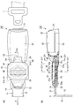
図1〜図3に示すように、本発明の第1実施形態のシートベルトのバックル装置10は、車体側に取付可能なアンカープレート11と、シートベルトのタング1が着脱自在に装着可能なバックル20と、アンカープレート11とバックル20とを連結する帯状の織布30と、を有する。(First embodiment)
As shown in FIGS. 1 to 3, a seat
アンカープレート11は、締結孔12内にボルト(図示せず)を挿入して車体側の床面とボルト締結される平面部13と、この平面部13から折り曲げられ、端部に孔部14が形成された起立部15とを有し、略L字状に形成される。
The
バックル20は、一端側にタング挿入部21を有するとともに、他端側で一対の樹脂カバー22,23に形成された凹部24間に金属板部25を幅方向に掛け渡すことで、孔部26を形成する。
The
織布30は、アンカープレート11及びバックルに形成された各孔部14,26内に挿通して折り返され、3重に重ね合わされた部分にて縫合糸40を用いて縫合されている。織布30は、図3に示すように所定の長さにカットされ、四隅を面取りされた幅一定のウェビングであり、重ね合わせた際に内側に折り込まれる折り込み部分31と、アンカープレート11の孔部14にて折り返される下側折り返し部分32と、折り込み部分31から下側折り返し部分32を介して連続する表面部分33と、バックル20の孔部26にて折り返される上側折り返し部分34と、上側折り返し部分34から連続して、表面部分33とともに折り込み部分31を挟み込む裏面部分35と、を有する。即ち、織布30は、四隅以外の折り込み部分31から裏面部分35に亘って略一様幅を有する。
The woven
アンカープレート11及びバックル20の各孔部14,26に位置する、下側及び上側折り返し部分32,34は、図2(a)及び(b)に示すように、これら部分32,34での断面係数を増加するように、幅方向の両縁部32a,34aを幅方向中間部に向けて内側に折畳んでいる。また、3重に重ね合わされる折り込み部分31、表面部分33、及び裏面部分35は、長手方向両側で面取りされて下側及び上側折り返し部分32,34より幅広に形成されており、この重ね合わされた長手方向略中間部分を図1(a)に示すように縫合することで、アンカープレート11とバックル20とを連結する。
The lower and upper folded
このように縫製された織布30では、図2(a)に示すように、内側に折り込まれる折り込み部分31の先端部31aが、長手方向同位置での表面及び裏面部分33,35と略等しい幅で、対向するバックル20の金属板部25に当接されている。これにより、織布30によってバックル装置10の所定の剛性が保たれ、バックル20の自立性を向上できるとともに、乗員の着座性を向上することができる。
In the woven
また、織布30は、アンカープレート11及びバックル20に形成された各孔部14,26内を挿通して折り返され、3重に重ね合わされた部分にて縫合される重ね合わせ部分を備えており、アンカープレート11及びバックル20の各孔部14,26において、幅方向の両縁部32a,34aを幅方向中間部に向けて内側に折り畳まれている。少なくとも3重に重ね合わされた部分で縫合され、その縫合部分は、織布30の幅方向端部近傍まで設けられている。前記の両側に折り畳まれた両端部32a,34aと、この織布30の幅方向近傍まで設けられた縫合部分とにより、乗員の着座時の障害となるのを防ぎながら、バックル20の自立性を確保する剛性を得る。
In addition, the woven
なお、織布30同士が接触する面、具体的に、折り返し部分32,34の両縁部32a,34aや、裏面部分35の端部35aと折り込み部分31が接触する部分等は、接着等によって接合されている。
In addition, the surface where the woven
また、バックル装置10を製造する際には、織布30の各折り返し部分32,34と、表面部分33と、折り込み部分31と裏面部分35の何れか一方とを、その幅方向の両縁部を幅方向中間部に向けて内側に折り畳んだ状態で、折り込み部分31と裏面部分35の他方を残して、各孔部14,26に挿通させる。そして、各折り返し部分32,34における幅方向の両縁部32a,34aが幅方向中間部に向けて内側に折り畳んだ状態のまま、折り畳んだ表面部分33と、折り込み部分31と裏面部分35の何れか一方とを広げ、少なくとも3重に重ね合わされた部分31,33,35を縫合する。
When manufacturing the
或いは、織布30の各折り返し部分32,34と、折り込み部分31と、裏面部分35とを、その幅方向の両縁部を幅方向中間部に向けて内側に折り畳んだ状態で、表面部分33を残して、各孔部14,26に挿通させる。そして、各折り返し部分32,34における幅方向の両縁部32a,34aが幅方向中間部に向けて内側に折り畳んだ状態のまま、折り込み部分31と裏面部分35とを広げ、少なくとも3重に重ね合わされた部分31,33,35を縫合する。
Alternatively, each of the folded
(第2実施形態)
図4及び図5に示す第2実施形態のシートベルトのバックル装置10aでは、織布30に仮縫いが施される点において、第1実施形態のものと異なる。(Second Embodiment)
The seat
即ち、織布30は、内側に折り込まれる折り込み部分31と、アンカープレート11の孔部14を通過した折り込み部分31から連続する表面部分33とを重ね合わせた部分が縫合糸40よりアンカープレート側において縫合糸41によって仮縫いされている。
That is, in the woven
従って、このようなバックル装置10aでは、まず、図5に示すように、織布30の折り込み部分31をアンカープレート11の孔部14内に挿通して、下側折り返し部分32にて折り返した後、折り込み部分31と表面部分33とが2重に重ね合わされる部分で仮縫いする。そして、裏面部分35をバックル20の孔部26内に挿通し、重ね合わされた織布30の先端部31aをバックル20の金属板部25と当接させると共に、上側折り返し部分34にて折り返した後、3重に重ね合わされた部分を縫合する。
Therefore, in such a
このように仮縫いを行うことで、織布30の全長が短い等、3重に重ね合わされた部分を一度に縫製することが困難な場合に、一度アンカープレート側を仮縫いすることで、縫製する際に重ね合わせ部分のずれを防止でき、縫製の作業性を向上できる。また、内側に折り込まれる織布30の先端部31aを確実にバックル20に当接させることができ、織布30の剛性向上も図れる。
なお、その他の構成及び作用については、第1実施形態のものと同様である。When sewing is performed by temporarily sewing the anchor plate side once when it is difficult to sew the overlapped portions at once, such as when the total length of the woven
Other configurations and operations are the same as those in the first embodiment.
(第3実施形態)
図6及び図7に示す第3実施形態のシートベルトのバックル装置10bでは、織布30が折り返される部分から重ね合わせ部分に亘って樹脂製のシート50,51が介装される点において第1実施形態のものと異なる。(Third embodiment)
In the seat
本例では、具体的に、樹脂製のシート50,51は、厚さ0.8mm程度のポリプロピレン等からなり、縫合糸40の縫合部分よりアンカープレート側、バックル側にそれぞれ分割配置されている。アンカープレート側のシート50は、下側折り返し部分32の幅方向両縁部32aが折畳まれる折畳み部分間に挟まれて、折り込み部分31と表面部分33との重ね合わせ部分に延びる。バックル側のシート51も、上側折り返し部分34の幅方向両縁部34aが折畳まれる折畳み部分間に挟まれて、折り込み部分31と表面部分33との重ね合わせ部分に延びる。このように樹脂製のシート50,51を織布30に介装させることで、縫合部分とアンカープレート11、或いは、縫合部分とバックル20との間部分の剛性を向上することができる。また、これらのシート50,51は織布30に介装されているので、シート50,51が外れることがなく、また、シート50,51が外部から隠れているので良好な外観性を維持できる。
その他の構成及び作用については、第1実施形態のものと同様である。In this example, specifically, the
Other configurations and operations are the same as those in the first embodiment.
なお、図8に示す変形例に係るシートベルト装置10cのように、織布30が縫合される縫合部分を幅方向に分割し、樹脂製のシート52を縫合部分から外れた幅方向中間位置に通過させ、アンカープレート11及びバックル20の各孔部14,26近傍まで連続するようにしてもよい。これにより、1枚の樹脂製のシート52で上記と同様の効果を奏することができる。
As in the
(第4実施形態)
図9に示す第4実施形態のシートベルトのバックル装置10dでは、織布が縫合される縫合部分において第2実施形態のものと異なる。(Fourth embodiment)
The seat
即ち、織布30は、3重に重ね合わされた部分における折畳み部分近傍位置まで延長して縫合されている。アンカープレート11及びバックル20の各孔部14,26において、幅方向の両縁部32a,34aを幅方向中間部に向けて内側に折畳んだ部分では、織布30が厚くなることで剛性が確保され、長手方向両側の折畳み部分間の3重に重ね合わせた部分も、縫合部分が長手方向に延長されている。従って、織布30の剛性が高まった領域が拡大され、織布30の剛性が、長手方向全域に亘って向上される。
なお、その他の構成及び作用については、第2実施形態のものと同様である。In other words, the woven
Other configurations and operations are the same as those in the second embodiment.
(第5実施形態)
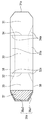
図10及び図11に示す第5実施形態のシートベルトのバックル装置10eでは、織布の縫合される部分の形状において第4実施形態のものと異なる。(Fifth embodiment)
The seat
本実施形態においても、織布30は3重に重ね合わされた部分の折畳み部分近傍位置まで縫合されているが、図11(c)に示すように、重ね合わされた部分がアーチ断面形状となるように縫合する。このような断面形状とすることで、重ね合わせ部分の断面係数を増加して剛性を向上することができる。なお、このような断面形状に縫合する際には、図12に示すように、アーチ形状のミシンの受け台60上に重ね合わせ部分を載せ、縫い針61を用いて縫合することで、上記アーチ断面形状に縫製されてもよい。
その他の構成及び作用については、第4実施形態のものと同様である。Also in the present embodiment, the woven
Other configurations and operations are the same as those of the fourth embodiment.
(第6実施形態)
図13及び図14に示す第6実施形態のシートベルトのバックル装置10fでは、織布30の周囲を、樹脂部材によって覆う点おいて第5実施形態のものと異なる。(Sixth embodiment)
The seat
即ち、本実施形態では、樹脂部材であるチューブ70をアンカープレート11側から挿入して、アーチ断面形状に形成された織布30の周囲に取り付ける。チューブ70は伸びの少ない樹脂材料からなり、その内周長は、織布30の断面周長よりも短く形成され、織布30の周囲にはまり込む。従って、織布30のアーチ断面形状をチューブ70によって維持することができ、織布30の剛性向上を図ることができる。
その他の構成及び作用については、第5実施形態のものと同様である。なお、樹脂部材としては、チューブ70の代わりに、織布30の周囲を樹脂テープで巻いて織布30のアーチ断面形状を維持するようにしてもよい。That is, in this embodiment, the
Other configurations and operations are the same as those of the fifth embodiment. In addition, as a resin member, you may make it maintain the arch cross-sectional shape of the woven
(第7実施形態)
図15〜図17に示す第7実施形態のシートベルトのバックル装置10gでは、織布30の表面部分33を折り畳んだ状態で縫合される点において、第1実施形態のものと異なる。(Seventh embodiment)
The seat
即ち、本実施形態を含めた上述の実施形態では、織布30の重ね合わせ部分において、バックル20の孔部26とアンカープレート11の孔部14を挿通する各折り返し部分32,34間の表面部分33は、その幅方向の両縁部33aを幅方向中間部に向けて内側に折り畳んだ状態としている。上述の実施形態では、この表面部分33は一方の孔部14,26を通過した後に広げられて縫合されているが、本実施形態では、表面部分33は上記のように折り畳まれた状態で、折り込み部分31と裏面部分35と共に縫合される。このため、織布30は、図17に点線で示すように、表面部分33の幅方向の両縁部33aが下側及び上側折り返し部分32,34の幅方向両縁部32a,34aから連続して折り畳まれた状態で縫合される。これにより、さらに織布30の曲げ剛性が向上し、織布30の自立性を確保できる。なお、本実施形態では、第4実施形態と同様、織布30は、3重に重ね合わされた部分における折り畳み部分32a,34a近傍位置まで縫合されている。
その他の構成及び作用については、第1実施形態のものと同様である。That is, in the above-described embodiments including this embodiment, in the overlapping portion of the woven
Other configurations and operations are the same as those in the first embodiment.
(第8実施形態)
図18及び図19に示す第8実施形態のシートベルトのバックル装置10hでは、渡り縫製をしてアーチ断面形状とする点において、第7実施形態のものと異なる。(Eighth embodiment)
The
即ち、第7実施形態と同様、織布30は、表面部分33の幅方向の両縁部を幅方向中間部に向けて内側に折り畳んだ状態で縫合されている(図19(a)参照。)。本実施形態では、さらに、図19(b)に示すように、織布30は、アーチ形状のミシンの受け台60上に重ね合わせ部分を載せ、縫い針62を用いて表面部分33の折り曲げ部分33bを跨ぐように折り返し部分32,34の近傍位置まで、その幅方向において折り込み部分31から表面部分33を通り折り込み部分31へ渡るように渡り縫合される。従って、本実施形態は、折り畳まれた表面部分33がより確実に縫合されるとともに、重ね合わせ部分がアーチ断面形状となって断面係数が増加し、さらに剛性を向上することができる。
その他の構成及び作用については、第7実施形態のものと同様である。That is, as in the seventh embodiment, the woven
Other configurations and operations are the same as those of the seventh embodiment.
(第9実施形態)
図20〜図22に示す第9実施形態のシートベルトのバックル装置10iでは、バックル20の孔部26を通過した織布30の部分を先端部31aがアンカープレート11と当接する折り込み部分31とし、アンカープレート11の孔部14を通過した織布30の図面下側部分を裏面部分35としている。そして、この裏面部分35がバックル20の孔部26の近傍まで延長されることで、織布30の剛性を上げている。(Ninth embodiment)
In the seat
また、織布30の一対の傾斜部35a1とこれら傾斜部35a1間の中間部35a2からなる、裏面部分35の長手方向の先端部35aは、ヒートカットの際、多めに溶かすことで、織布30の厚さ以上の寸法を有する玉縁形状に形成されて、先端部36の剛性を向上している。さらに、裏面部分35は、その長手方向の縫合部分から先端部35aまでの領域内で、内側表面と外側表面の少なくとも一方の表面37における糸同士が熱溶融されて固着されている部分を有するので、この先端部35aが樹脂板化して曲げ剛性を向上させることができる。この場合、織布30の裏面部分35は折り曲げ難くなっているので、折り込み部分31がアンカープレート11の孔部14とバックル20の孔部26に通されて縫合される。
Moreover, the front-end | tip
また、織布30には、強度を受ける縦糸の幅方向外側に、フィーリングを向上するための耳糸と、横糸のほつれ防止のためのキャッチスレッドが設けられている。そこで、織布30の耳部38におけるこれらの糸を、熱溶融して固着することで、強度やほつれ防止に影響を与えることなく、全体としての剛性を上げることができる。
その他の構成及び作用については、第7実施形態のものと同様である。なお、上記実施形態と同じく、アンカープレート11の孔部14を通過した織布30の部分をバックルの金属板部25と当接する折り込み部分31とし、バックル20の孔部26を通過した織布30の部分を裏面部分35として、この裏面部分35がアンカープレート11の孔部14の近傍まで延長されてもよい。Further, the woven
Other configurations and operations are the same as those of the seventh embodiment. As in the above-described embodiment, the portion of the woven
なお、本発明は上記実施形態例に限定されるものではなく、適宜、変形、改良等が可能である。また、各実施形態は、実施可能な範囲において組み合わせて適用することも可能であり、各実施形態の特徴は、単独で本発明の目的を達成することも可能である。 In addition, this invention is not limited to the said embodiment, A deformation | transformation, improvement, etc. are possible suitably. In addition, the embodiments can be applied in combination within a feasible range, and the features of the embodiments can achieve the object of the present invention alone.
例えば、第2〜第9実施形態は、第1実施形態の特徴である、内側に折り込まれる織布30の先端部31aをバックル20に当接する構成を兼ね備えることが好ましいが、第2〜第9実施形態の特徴は、第1実施形態の特徴の有無に関わらず、本発明の目的を達成することができる。
For example, in the second to ninth embodiments, it is preferable to combine the configuration in which the
加えて、上記実施形態例では、内側に折り込まれる織布30の先端部31aをバックル20に当接しているが、先端部31aをアンカープレート11に当接させるようにしても同様の効果を奏することができる。
In addition, in the above embodiment, the
なお、本出願は、2007年9月11日出願の日本特許出願(特願2007−235456)に基づくものであり、その内容はここに参照として取り込まれる。 This application is based on a Japanese patent application (Japanese Patent Application No. 2007-235456) filed on Sep. 11, 2007, the contents of which are incorporated herein by reference.
Claims (23)
シートベルトのタングが着脱自在に装着可能なバックルと、
前記アンカープレート及び前記バックルに形成された各孔部内を挿通して折り返され、少なくとも3重に重ね合わされる織布と、
を備えるシートベルトのバックル装置であって、
前記重ね合わされる部分は、内側に折り込まれる折り込み部分と、当該折り込み部分から折り返されて連続する表面部分と、当該表面部分から折り返されて連続する裏面部分と、を有し、
前記織布の前記アンカープレート及び前記バックルに形成された各孔部を挿通して折り返される各折り返し部分は、その幅方向の両縁部を幅方向中間部に向けて内側に折り畳んで構成され、
前記織布は、少なくとも3重に重ね合わされた部分で縫合されることを特徴とするシートベルトのバックル装置。An anchor plate that can be attached to the vehicle body,
A buckle on which the tongue of the seat belt can be detachably attached,
A woven fabric that is inserted and folded through each hole formed in the anchor plate and the buckle, and is overlapped at least three times;
A seat belt buckle device comprising:
The overlapped portion has a folded portion that is folded inward, a front surface portion that is folded back from the folded portion and is continuous, and a back surface portion that is folded back from the surface portion and is continuous.
Each folded portion that is folded by passing through each hole formed in the anchor plate and the buckle of the woven fabric is configured by folding both edges in the width direction toward the middle in the width direction,
The seat belt buckle device, wherein the woven fabric is stitched at a portion where at least three layers are overlapped.
前記折り込み部分から前記裏面部分に亘って略一様幅を有する前記織布の一部を、その幅方向の両縁部を幅方向中間部に向けて内側に折り畳んだ状態で、前記各孔部に挿通させる工程と、
前記織布の前記各孔部を挿通して折り返される各折り返し部分における幅方向の両縁部が幅方向中間部に向けて内側に折り畳んだ状態のまま、少なくとも3重に重ね合わされた部分を縫合する工程と、
を備えることを特徴とするシートベルトのバックル装置の製造方法。An anchor plate that can be attached to the vehicle body side, a buckle on which a tongue of a seat belt can be detachably attached, and a folded portion that is folded back and inserted through each hole formed in the anchor plate and the buckle A seat belt buckle device comprising: a front surface portion folded back from the folded portion and a continuous back surface portion folded back from the front surface portion; A manufacturing method of
Each of the hole portions in a state in which a part of the woven fabric having a substantially uniform width from the folded portion to the back surface portion is folded inward with both edges in the width direction facing the intermediate portion in the width direction. A process of passing through,
At least three overlapping portions are stitched while both edges in the width direction of the folded portions that are folded through the holes of the woven fabric are folded inward toward the intermediate portion in the width direction. And a process of
A method of manufacturing a seat belt buckle device.
シートベルトのタングが着脱自在に装着可能なバックルと、
織布が、前記アンカープレート及び前記バックルに形成された各孔部内を挿通して折り返され、少なくとも3重に重ね合わされた部分にて縫合される重ね合わせ部分と、
を備えるシートベルトのバックル装置であって、
前記織布が折り返されることで重ね合わされる重ね合わせ部分には、樹脂製のシートが収容されることを特徴とするシートベルトのバックル装置。An anchor plate that can be attached to the vehicle body,
A buckle on which the tongue of the seat belt can be detachably attached,
A woven fabric is inserted through each hole formed in the anchor plate and the buckle, folded back, and stitched together at least in a three-ply portion,
A seat belt buckle device comprising:
A buckle device for a seat belt, wherein a resin sheet is accommodated in an overlapping portion where the woven fabric is folded and overlapped.
シートベルトのタングが着脱自在に装着可能なバックルと、
織布が、前記アンカープレート及び前記バックルに形成された各孔部内を挿通して折り返され、少なくとも3重に重ね合わされた部分にて縫合される重ね合わせ部分と、
を備えるシートベルトのバックル装置であって、
前記織布は、前記アンカープレート及び前記バックルの各孔部において、幅方向の両縁部を幅方向中間部に向けて内側に折り畳まれており、且つ、
前記織布は、前記重ね合わせ部分における前記折り返された部分の近傍位置まで縫合されていることを特徴とするシートベルトのバックル装置。An anchor plate that can be attached to the vehicle body,
A buckle on which the tongue of the seat belt can be detachably attached,
A woven fabric is inserted through each hole formed in the anchor plate and the buckle, folded back, and stitched together at least in a three-ply portion,
A seat belt buckle device comprising:
The woven fabric is folded inward in the hole portions of the anchor plate and the buckle, with both edges in the width direction facing the intermediate portion in the width direction, and
The seat belt buckle device, wherein the woven fabric is sewn to a position near the folded portion in the overlapped portion.
Priority Applications (1)
| Application Number | Priority Date | Filing Date | Title |
|---|---|---|---|
| JP2009532208A JP5233036B2 (en) | 2007-09-11 | 2008-09-11 | Seat belt buckle device and manufacturing method thereof |
Applications Claiming Priority (4)
| Application Number | Priority Date | Filing Date | Title |
|---|---|---|---|
| JP2007235456 | 2007-09-11 | ||
| JP2007235456 | 2007-09-11 | ||
| PCT/JP2008/066388 WO2009035022A1 (en) | 2007-09-11 | 2008-09-11 | Buckle device for seatbelt and method of manufacturing the same |
| JP2009532208A JP5233036B2 (en) | 2007-09-11 | 2008-09-11 | Seat belt buckle device and manufacturing method thereof |
Publications (2)
| Publication Number | Publication Date |
|---|---|
| JPWO2009035022A1 JPWO2009035022A1 (en) | 2010-12-24 |
| JP5233036B2 true JP5233036B2 (en) | 2013-07-10 |
Family
ID=40452029
Family Applications (1)
| Application Number | Title | Priority Date | Filing Date |
|---|---|---|---|
| JP2009532208A Active JP5233036B2 (en) | 2007-09-11 | 2008-09-11 | Seat belt buckle device and manufacturing method thereof |
Country Status (5)
| Country | Link |
|---|---|
| US (1) | US8650721B2 (en) |
| EP (3) | EP2511142B1 (en) |
| JP (1) | JP5233036B2 (en) |
| CN (4) | CN101801738B (en) |
| WO (1) | WO2009035022A1 (en) |
Families Citing this family (13)
| Publication number | Priority date | Publication date | Assignee | Title |
|---|---|---|---|---|
| US8650721B2 (en) | 2007-09-11 | 2014-02-18 | Autoliv Development Ab | Buckle device for seat belt and manufacturing method thereof |
| GB2471090A (en) * | 2009-06-16 | 2010-12-22 | Autoliv Dev | A connector arrangement |
| DE102012000202B4 (en) * | 2012-01-09 | 2022-08-18 | Zf Automotive Germany Gmbh | Device for anchoring a belt buckle and device arrangement with at least two such devices |
| CN103111836B (en) * | 2013-03-07 | 2016-02-17 | 上海天合汽车安全系统有限公司 | A kind of spring leaf assembly system |
| US9586558B2 (en) * | 2013-10-30 | 2017-03-07 | GM Global Technology Operations LLC | Buckle assembly for a vehicle |
| EP3191349B1 (en) * | 2014-09-10 | 2018-06-13 | Zodiac Seats US LLC | Seat belt twist link |
| US20160311396A1 (en) * | 2015-04-24 | 2016-10-27 | GM Global Technology Operations LLC | Belt buckle anchor for thin seats |
| CN106555279B (en) * | 2015-09-25 | 2022-05-31 | 东莞市春藤实业有限公司 | Automatic fastener assembling line turning equipment |
| CN105533964B (en) * | 2016-02-06 | 2017-07-11 | 芊茂(浙江)拉链有限公司 | The case and bag suture processing method of two-way correspondence bond-allocating open end zipper and the case and bag structure for configuring dual-end slide fastener |
| TWI616152B (en) * | 2016-02-18 | 2018-03-01 | Gnmo Zipper Corp | Case stitching processing method for two-way corresponding positioning configuration open zipper and luggage structure for configuring double-end open zipper |
| DE102017118756A1 (en) * | 2017-08-17 | 2019-02-21 | Trw Automotive Gmbh | Belt retractor and method for manufacturing a belt retractor |
| US11285911B2 (en) * | 2020-02-25 | 2022-03-29 | Volvo Car Corporation | Vehicle seat belt assembly |
| CN111546643B (en) * | 2020-03-27 | 2022-02-01 | 平湖尚珠体育用品有限公司 | Full-automatic ultrasonic welding machine |
Citations (2)
| Publication number | Priority date | Publication date | Assignee | Title |
|---|---|---|---|---|
| JPS5820661U (en) * | 1981-07-31 | 1983-02-08 | 松岡 喜一郎 | Cleaner using liquid-vapor mixing nozzle |
| JPS61121742U (en) * | 1985-01-18 | 1986-07-31 |
Family Cites Families (24)
| Publication number | Priority date | Publication date | Assignee | Title |
|---|---|---|---|---|
| US4103933A (en) * | 1976-01-12 | 1978-08-01 | Robert C. Fisher | Floor anchor for seat belt |
| JPS5621412Y2 (en) * | 1976-06-08 | 1981-05-20 | ||
| JPS59127652U (en) * | 1983-02-14 | 1984-08-28 | 本田技研工業株式会社 | Seatbelt holding boots for seatbelt attachment aids |
| JPS6185551U (en) * | 1984-11-12 | 1986-06-05 | ||
| JPH056210Y2 (en) * | 1985-07-06 | 1993-02-17 | ||
| JPS6211055A (en) | 1985-07-09 | 1987-01-20 | Nikko Seiki Kk | Production apparatus of folded confectionery |
| JPS6325669A (en) | 1986-07-18 | 1988-02-03 | Canon Inc | Developing device |
| JPS6325669U (en) * | 1986-08-05 | 1988-02-19 | ||
| JPS6328056U (en) * | 1986-08-07 | 1988-02-24 | ||
| JPH01117963A (en) | 1987-10-30 | 1989-05-10 | Mazda Motor Corp | Idling engine speed controller for engine |
| JPH01117963U (en) | 1988-02-04 | 1989-08-09 | ||
| EP0327968B1 (en) * | 1988-02-08 | 1993-08-11 | Nippon Seiko Kabushiki Kaisha | Buckle stalk for seat belt system |
| JP2949724B2 (en) | 1989-07-11 | 1999-09-20 | 日本電気株式会社 | Semiconductor substrate storage container |
| JPH0735800Y2 (en) * | 1989-08-03 | 1995-08-16 | 日本精工株式会社 | Buckle stokes for seat belts |
| JPH0732284Y2 (en) * | 1989-09-08 | 1995-07-26 | 本田技研工業株式会社 | Seat belt end self-supporting mechanism |
| DE19530445C2 (en) * | 1995-08-18 | 1998-02-26 | Mc Micro Compact Car Ag | Belt buckle holder made of stiffened webbing for a seat belt in a motor vehicle |
| WO2004005074A2 (en) * | 2002-07-10 | 2004-01-15 | Automotive Systems Laboratory, Inc. | Method of attaching a seat belt to a seat belt tension sensor |
| GB2391038A (en) * | 2002-07-19 | 2004-01-28 | Autoliv Dev | A seat belt buckle arrangement |
| EP1557327A1 (en) * | 2004-01-21 | 2005-07-27 | Key Safety Systems, Inc. | Buckle assembly |
| WO2006076541A2 (en) * | 2005-01-13 | 2006-07-20 | Takata Seat Belts, Inc. | Buckle support assembly and manufacturing method and system |
| JP4381997B2 (en) * | 2005-02-04 | 2009-12-09 | 株式会社東海理化電機製作所 | Buckle device |
| US7383620B2 (en) * | 2005-05-11 | 2008-06-10 | Takata Seat Belts, Inc. | Buckle support assembly |
| JP4987322B2 (en) | 2006-02-28 | 2012-07-25 | 株式会社東芝 | Moving picture decoding apparatus and moving picture decoding method |
| US8650721B2 (en) | 2007-09-11 | 2014-02-18 | Autoliv Development Ab | Buckle device for seat belt and manufacturing method thereof |
-
2008
- 2008-09-11 US US12/676,800 patent/US8650721B2/en active Active
- 2008-09-11 CN CN2008801062351A patent/CN101801738B/en active Active
- 2008-09-11 WO PCT/JP2008/066388 patent/WO2009035022A1/en active Application Filing
- 2008-09-11 CN CN201210083115.2A patent/CN102632861B/en active Active
- 2008-09-11 CN CN201210083114.8A patent/CN102632860B/en active Active
- 2008-09-11 CN CN201210083113.3A patent/CN102632859B/en active Active
- 2008-09-11 EP EP12171137.8A patent/EP2511142B1/en active Active
- 2008-09-11 EP EP08830977.8A patent/EP2199159B1/en active Active
- 2008-09-11 EP EP12171148.5A patent/EP2505437B1/en active Active
- 2008-09-11 JP JP2009532208A patent/JP5233036B2/en active Active
Patent Citations (2)
| Publication number | Priority date | Publication date | Assignee | Title |
|---|---|---|---|---|
| JPS5820661U (en) * | 1981-07-31 | 1983-02-08 | 松岡 喜一郎 | Cleaner using liquid-vapor mixing nozzle |
| JPS61121742U (en) * | 1985-01-18 | 1986-07-31 |
Also Published As
| Publication number | Publication date |
|---|---|
| EP2511142A3 (en) | 2012-11-21 |
| CN102632860B (en) | 2015-02-04 |
| EP2511142B1 (en) | 2014-04-30 |
| US20100257708A1 (en) | 2010-10-14 |
| EP2199159A1 (en) | 2010-06-23 |
| EP2505437A3 (en) | 2012-11-21 |
| CN102632859A (en) | 2012-08-15 |
| EP2505437B1 (en) | 2015-04-15 |
| CN101801738B (en) | 2012-06-13 |
| CN102632861A (en) | 2012-08-15 |
| WO2009035022A1 (en) | 2009-03-19 |
| CN101801738A (en) | 2010-08-11 |
| EP2505437A2 (en) | 2012-10-03 |
| EP2511142A2 (en) | 2012-10-17 |
| EP2199159A4 (en) | 2011-11-30 |
| CN102632859B (en) | 2014-09-03 |
| JPWO2009035022A1 (en) | 2010-12-24 |
| US8650721B2 (en) | 2014-02-18 |
| CN102632861B (en) | 2015-02-04 |
| EP2199159B1 (en) | 2014-07-16 |
| CN102632860A (en) | 2012-08-15 |
Similar Documents
| Publication | Publication Date | Title |
|---|---|---|
| JP5233036B2 (en) | Seat belt buckle device and manufacturing method thereof | |
| JP5446657B2 (en) | Air belt and air belt device | |
| TWI546024B (en) | Zipper-attached items and zipper-attached articles, and chain and zipper | |
| EP0128662A2 (en) | Safety belt | |
| WO2007052453A1 (en) | Vehicle seatbelt | |
| JP2008247087A (en) | Occupant restraint system | |
| EP1288085A2 (en) | Protective cushion for protection of vehicle occupant's head | |
| JP2010125992A (en) | Jacket with airbag | |
| JPH11348719A (en) | Air belt | |
| JP3767173B2 (en) | Air belt bag | |
| JP4966569B2 (en) | Airbag | |
| CA2085702A1 (en) | Structure for stitching a tether belt of an air bag | |
| US20030207068A1 (en) | Method of processing product using fabric and product thereof | |
| JP2000203380A (en) | Air-belt and air-belt device | |
| JP5992202B2 (en) | Seat belt device | |
| JP2002002442A (en) | Air belt member | |
| JPH0752736A (en) | Expansive structural body of seat belt device | |
| US20080061620A1 (en) | Seatbelt assembly for improved belt safety and comfort | |
| JPH0769150A (en) | Air bag for vehicle | |
| JPH05278543A (en) | Cloth sewing structure of air bag | |
| JP2024125097A (en) | Seat back | |
| JPH05229393A (en) | Air bag body of air bag device | |
| WO2013077091A1 (en) | Bag, air belt, and air-belt device | |
| JPH057885Y2 (en) | ||
| CN117922403A (en) | Headrest cover |
Legal Events
| Date | Code | Title | Description |
|---|---|---|---|
| A621 | Written request for application examination |
Free format text: JAPANESE INTERMEDIATE CODE: A621 Effective date: 20110614 |
|
| TRDD | Decision of grant or rejection written | ||
| A01 | Written decision to grant a patent or to grant a registration (utility model) |
Free format text: JAPANESE INTERMEDIATE CODE: A01 Effective date: 20130226 |
|
| A61 | First payment of annual fees (during grant procedure) |
Free format text: JAPANESE INTERMEDIATE CODE: A61 Effective date: 20130306 |
|
| R150 | Certificate of patent or registration of utility model |
Free format text: JAPANESE INTERMEDIATE CODE: R150 |
|
| FPAY | Renewal fee payment (event date is renewal date of database) |
Free format text: PAYMENT UNTIL: 20160405 Year of fee payment: 3 |
|
| R250 | Receipt of annual fees |
Free format text: JAPANESE INTERMEDIATE CODE: R250 |
|
| R250 | Receipt of annual fees |
Free format text: JAPANESE INTERMEDIATE CODE: R250 |
|
| R250 | Receipt of annual fees |
Free format text: JAPANESE INTERMEDIATE CODE: R250 |
|
| R250 | Receipt of annual fees |
Free format text: JAPANESE INTERMEDIATE CODE: R250 |