EP2199159B1 - Buckle device for seatbelt and method of manufacturing the same - Google Patents
Buckle device for seatbelt and method of manufacturing the same Download PDFInfo
- Publication number
- EP2199159B1 EP2199159B1 EP08830977.8A EP08830977A EP2199159B1 EP 2199159 B1 EP2199159 B1 EP 2199159B1 EP 08830977 A EP08830977 A EP 08830977A EP 2199159 B1 EP2199159 B1 EP 2199159B1
- Authority
- EP
- European Patent Office
- Prior art keywords
- woven fabric
- buckle
- seat belt
- belt according
- buckle device
- Prior art date
- Legal status (The legal status is an assumption and is not a legal conclusion. Google has not performed a legal analysis and makes no representation as to the accuracy of the status listed.)
- Active
Links
- 238000004519 manufacturing process Methods 0.000 title description 3
- 239000002759 woven fabric Substances 0.000 claims description 107
- 239000011347 resin Substances 0.000 claims description 18
- 229920005989 resin Polymers 0.000 claims description 18
- 238000002844 melting Methods 0.000 claims description 6
- 239000002184 metal Substances 0.000 claims description 6
- 238000009958 sewing Methods 0.000 description 10
- 230000000694 effects Effects 0.000 description 2
- QNRATNLHPGXHMA-XZHTYLCXSA-N (r)-(6-ethoxyquinolin-4-yl)-[(2s,4s,5r)-5-ethyl-1-azabicyclo[2.2.2]octan-2-yl]methanol;hydrochloride Chemical compound Cl.C([C@H]([C@H](C1)CC)C2)CN1[C@@H]2[C@H](O)C1=CC=NC2=CC=C(OCC)C=C21 QNRATNLHPGXHMA-XZHTYLCXSA-N 0.000 description 1
- 239000004743 Polypropylene Substances 0.000 description 1
- 238000003780 insertion Methods 0.000 description 1
- 230000037431 insertion Effects 0.000 description 1
- 239000000463 material Substances 0.000 description 1
- 238000000034 method Methods 0.000 description 1
- 230000002093 peripheral effect Effects 0.000 description 1
- -1 polypropylene Polymers 0.000 description 1
- 229920001155 polypropylene Polymers 0.000 description 1
- 230000002265 prevention Effects 0.000 description 1
Images


Classifications
-
- B—PERFORMING OPERATIONS; TRANSPORTING
- B60—VEHICLES IN GENERAL
- B60R—VEHICLES, VEHICLE FITTINGS, OR VEHICLE PARTS, NOT OTHERWISE PROVIDED FOR
- B60R22/00—Safety belts or body harnesses in vehicles
- B60R22/12—Construction of belts or harnesses
-
- B—PERFORMING OPERATIONS; TRANSPORTING
- B60—VEHICLES IN GENERAL
- B60R—VEHICLES, VEHICLE FITTINGS, OR VEHICLE PARTS, NOT OTHERWISE PROVIDED FOR
- B60R22/00—Safety belts or body harnesses in vehicles
- B60R22/18—Anchoring devices
- B60R2022/1806—Anchoring devices for buckles
-
- B—PERFORMING OPERATIONS; TRANSPORTING
- B60—VEHICLES IN GENERAL
- B60R—VEHICLES, VEHICLE FITTINGS, OR VEHICLE PARTS, NOT OTHERWISE PROVIDED FOR
- B60R22/00—Safety belts or body harnesses in vehicles
- B60R22/18—Anchoring devices
- B60R22/22—Anchoring devices secured to the vehicle floor
-
- Y—GENERAL TAGGING OF NEW TECHNOLOGICAL DEVELOPMENTS; GENERAL TAGGING OF CROSS-SECTIONAL TECHNOLOGIES SPANNING OVER SEVERAL SECTIONS OF THE IPC; TECHNICAL SUBJECTS COVERED BY FORMER USPC CROSS-REFERENCE ART COLLECTIONS [XRACs] AND DIGESTS
- Y10—TECHNICAL SUBJECTS COVERED BY FORMER USPC
- Y10T—TECHNICAL SUBJECTS COVERED BY FORMER US CLASSIFICATION
- Y10T24/00—Buckles, buttons, clasps, etc.
- Y10T24/40—Buckles
- Y10T24/4002—Harness
- Y10T24/4047—Strap loops and attaching devices
-
- Y—GENERAL TAGGING OF NEW TECHNOLOGICAL DEVELOPMENTS; GENERAL TAGGING OF CROSS-SECTIONAL TECHNOLOGIES SPANNING OVER SEVERAL SECTIONS OF THE IPC; TECHNICAL SUBJECTS COVERED BY FORMER USPC CROSS-REFERENCE ART COLLECTIONS [XRACs] AND DIGESTS
- Y10—TECHNICAL SUBJECTS COVERED BY FORMER USPC
- Y10T—TECHNICAL SUBJECTS COVERED BY FORMER US CLASSIFICATION
- Y10T24/00—Buckles, buttons, clasps, etc.
- Y10T24/40—Buckles
- Y10T24/4086—Looped strap
-
- Y—GENERAL TAGGING OF NEW TECHNOLOGICAL DEVELOPMENTS; GENERAL TAGGING OF CROSS-SECTIONAL TECHNOLOGIES SPANNING OVER SEVERAL SECTIONS OF THE IPC; TECHNICAL SUBJECTS COVERED BY FORMER USPC CROSS-REFERENCE ART COLLECTIONS [XRACs] AND DIGESTS
- Y10—TECHNICAL SUBJECTS COVERED BY FORMER USPC
- Y10T—TECHNICAL SUBJECTS COVERED BY FORMER US CLASSIFICATION
- Y10T24/00—Buckles, buttons, clasps, etc.
- Y10T24/45—Separable-fastener or required component thereof [e.g., projection and cavity to complete interlock]
- Y10T24/45225—Separable-fastener or required component thereof [e.g., projection and cavity to complete interlock] including member having distinct formations and mating member selectively interlocking therewith
- Y10T24/45241—Slot and tab or tongue
-
- Y—GENERAL TAGGING OF NEW TECHNOLOGICAL DEVELOPMENTS; GENERAL TAGGING OF CROSS-SECTIONAL TECHNOLOGIES SPANNING OVER SEVERAL SECTIONS OF THE IPC; TECHNICAL SUBJECTS COVERED BY FORMER USPC CROSS-REFERENCE ART COLLECTIONS [XRACs] AND DIGESTS
- Y10—TECHNICAL SUBJECTS COVERED BY FORMER USPC
- Y10T—TECHNICAL SUBJECTS COVERED BY FORMER US CLASSIFICATION
- Y10T24/00—Buckles, buttons, clasps, etc.
- Y10T24/45—Separable-fastener or required component thereof [e.g., projection and cavity to complete interlock]
- Y10T24/45225—Separable-fastener or required component thereof [e.g., projection and cavity to complete interlock] including member having distinct formations and mating member selectively interlocking therewith
- Y10T24/45602—Receiving member includes either movable connection between interlocking components or variable configuration cavity
- Y10T24/45623—Receiving member includes either movable connection between interlocking components or variable configuration cavity and operator therefor
-
- Y—GENERAL TAGGING OF NEW TECHNOLOGICAL DEVELOPMENTS; GENERAL TAGGING OF CROSS-SECTIONAL TECHNOLOGIES SPANNING OVER SEVERAL SECTIONS OF THE IPC; TECHNICAL SUBJECTS COVERED BY FORMER USPC CROSS-REFERENCE ART COLLECTIONS [XRACs] AND DIGESTS
- Y10—TECHNICAL SUBJECTS COVERED BY FORMER USPC
- Y10T—TECHNICAL SUBJECTS COVERED BY FORMER US CLASSIFICATION
- Y10T24/00—Buckles, buttons, clasps, etc.
- Y10T24/47—Strap-end-attaching devices
- Y10T24/4736—Buckle connected
-
- Y—GENERAL TAGGING OF NEW TECHNOLOGICAL DEVELOPMENTS; GENERAL TAGGING OF CROSS-SECTIONAL TECHNOLOGIES SPANNING OVER SEVERAL SECTIONS OF THE IPC; TECHNICAL SUBJECTS COVERED BY FORMER USPC CROSS-REFERENCE ART COLLECTIONS [XRACs] AND DIGESTS
- Y10—TECHNICAL SUBJECTS COVERED BY FORMER USPC
- Y10T—TECHNICAL SUBJECTS COVERED BY FORMER US CLASSIFICATION
- Y10T24/00—Buckles, buttons, clasps, etc.
- Y10T24/47—Strap-end-attaching devices
- Y10T24/4745—End clasp
-
- Y—GENERAL TAGGING OF NEW TECHNOLOGICAL DEVELOPMENTS; GENERAL TAGGING OF CROSS-SECTIONAL TECHNOLOGIES SPANNING OVER SEVERAL SECTIONS OF THE IPC; TECHNICAL SUBJECTS COVERED BY FORMER USPC CROSS-REFERENCE ART COLLECTIONS [XRACs] AND DIGESTS
- Y10—TECHNICAL SUBJECTS COVERED BY FORMER USPC
- Y10T—TECHNICAL SUBJECTS COVERED BY FORMER US CLASSIFICATION
- Y10T29/00—Metal working
- Y10T29/49—Method of mechanical manufacture
- Y10T29/49826—Assembling or joining
Definitions
- the present invention relates to a buckle device for a seat belt installed in a side portion of a vehicle seat.
- a three-point seat belt device employing webbing is used as a typical seat belt device for holding a vehicle occupant or the like safely in a seat.
- this type of seat belt device one end portion of the webbing is latched to a retractor and another end portion is latched to a lap anchor fixed to a vehicle body via a through anchor.
- a through tongue disposed in an intermediate portion of the webbing between the lap anchor and the through anchor with a buckle device fixed to a vehicle body inner side, the occupant is restrained in the seat.
- the buckle device is normally constituted by an anchor plate that can be attached to the vehicle body side, a buckle to which the tongue of the seat belt can be attached detachably, and a connecting member that connects the anchor plate to the buckle (see Patent Document 1, for example).
- Patent Document 1 Japanese Utility Model Application Publication No. H1-117963
- the buckle device when a buckle device is used in a rear seat of an automobile, the buckle device preferably possesses a predetermined rigidity that enables the buckle to self-stand relative to the anchor plate but does not cause an obstruction to a boarding/alighting occupant.
- the present invention has been designed in consideration of the circumstances described above, and an object thereof is to provide a buckle device for a seat belt constituted such that a predetermined rigidity is maintained by a woven fabric that connects a buckle to an anchor plate so that the buckle can be made self-standing, the buckle, despite being self-standing, does not cause an obstruction when an occupant sits down, and an improvement in the seating comfort of the occupant can be achieved.
- the present invention achieves the object described above by means of the following constitutions.
- the woven fabric is passed through the hole portions formed respectively in the anchor plate and the buckle, folded back so as to overlap at least triply, and sewn in the overlapping part. Further, the respective width direction edge portions of the respective folded-back parts folded back by passing the woven fabric through the hole portions formed respectively in the anchor plate and the buckle are doubled back on the inner side toward the width direction intermediate portion. Therefore, a predetermined rigidity can be maintained in the woven fabric over the overlapping part and the folded-back parts, and as a result, a self-standing property can be secured, enabling an improvement in the seating comfort of an occupant.
- the tip end portion of the woven fabric tucked into the inner side is caused to contact the opposing buckle or anchor plate, and therefore a further improvement in rigidity can be achieved by the woven fabric, enabling a further improvement in the seating comfort of the occupant.
- the doubly overlapped part is tacked after passing the woven fabric through one of the hole portions in the anchor plate and the buckle and folding the woven fabric back, the tip end portion of the overlapped woven fabric is caused to contact the other of the anchor plate and the buckle, and in this state, the woven fabric is passed through the other hole portion formed in the anchor plate or the buckle and folded back to form the triply overlapped part, whereupon the triply overlapped part is sewn.
- the overlapping part can be prevented from shifting during sewing and the tip end portion of the woven fabric tucked into the inner side can be brought into contact with the anchor plate or the buckle reliably, leading to improvements in the workability of the sewing operation and the rigidity of the woven fabric.
- the front surface part between the two hole portions which is formed by passing the woven fabric through one of the hole portions in the buckle and the anchor plate, is sewn in a state where the respective width direction edge portions thereof are doubled back on the inner side toward the width direction intermediate portion, and therefore the flexural rigidity of the woven fabric can be improved. As a result, the self-standing property of the woven fabric can be secured.
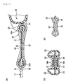
- a buckle device 10 for a seat belt includes an anchor plate 11 that can be attached to a vehicle body side, a buckle 20 to which a tongue 1 of the seat belt can be attached detachably, and a strip-form woven fabric 30 that connects the anchor plate 11 to the buckle 20.
- the anchor plate 11 is formed substantially in an L-shape and includes a planar portion 13 that is fastened by a bolt (not shown) to a floor surface on the vehicle body side by inserting the bolt into a fastening hole 12, and an upright portion 15 that is bent from the planar portion 13 and formed with a hole portion 14 in an end portion thereof.
- a tongue insertion portion 21 is provided on one end side of the buckle 20, and a hole portion 26 is formed on another end side by laying a metal plate portion 25 in a width direction across a recess portion 24 formed by a pair of resin covers 22, 23.
- the woven fabric 30 is passed through the hole portions 14, 26 formed respectively in the anchor plate 11 and buckle, folded back, and then sewn in a triply overlapped part using thread 40.
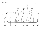
- the woven fabric 30 is formed from webbing having a constant width, which is cut into a predetermined length and chamfered on all four corners, and includes a tucked-in part 31 that is tucked into an inner side when the woven fabric 30 is overlapped, a lower side folded-back part 32 that is folded back at the hole portion 14 of the anchor plate 11, a front surface part 33 that forms a continuation of the tucked-in part 31 via the lower side folded-back part 32, an upper side folded-back part 34 that is folded back at the hole portion 26 of the buckle 20, and a rear surface part 35 that forms a continuation of the upper side folded-back part 34 and sandwiches the tucked-in part 31 together with the front surface part 33.
- the woven fabric 30 has a substantially uniform width from the tucked-in part 31 to
- respective width direction edge portions 32a, 34a of the lower side and upper side folded-back parts 32, 34 positioned respectively in the hole portions 14, 26 of the anchor plate 11 and the buckle 20 are doubled back on the inner side toward a width direction intermediate portion in order to increase a section modulus of these parts 32, 34.
- the triply overlapped tucked-in part 31, front surface part 33 and rear surface part 35 are chamfered on both lengthwise direction sides so as to have a greater width than the lower side and upper folded-back parts 32, 34, and by sewing a substantially intermediate overlapping part in the lengthwise direction as shown in Fig. 1(a) , the anchor plate 11 and the buckle 20 are connected.
- a tip end portion 31a of the tucked-in part 31 tucked into the inner side has a substantially identical width to the front surface and rear surface parts 33, 35 in an identical lengthwise direction position, and contacts the opposing metal plate portion 25 of the buckle 20.
- a predetermined rigidity is maintained in the buckle device 10 by the woven fabric 30, and as a result, a self-standing property of the buckle 20 and the seating comfort of an occupant can be improved.
- the woven fabric 30 includes the overlapping part that is folded back through the hole portions 14, 26 formed respectively in the anchor plate 11 and buckle 20 and sewn in the triply overlapped part, and the two width direction edge portions 32a, 34a are doubled back on the inner side toward the width direction intermediate portion in the respective hole portions 14, 26 of the anchor plate 11 and buckle 20.
- the woven fabric 30 is sewn in at least the triply overlapping part, and the sewn part is provided up to the vicinity of the width direction end portion of the woven fabric 30.
- the respective folded-back parts 32, 34, the front surface part 33 and one of the tucked-in part 31 and the rear surface part 35 of the woven fabric 30 are passed through the respective hole portions 14, 26 with both width direction edge portions thereof doubled back on the inner side toward the width direction intermediate portion while leaving the other of the tucked-in part 31 and the rear surface part 35 as is. Then, with the width direction edge portions 32a, 34a of the respective folded-back parts 32, 34 remaining doubled back on the inner side toward the width direction intermediate portion, the folded-back front surface part 33 and one of the tucked-in part 31 and the rear surface part 35 are unfolded, whereupon the at least triply overlapped part 31, 33, 35 is sewn.
- the respective folded-back parts 32, 34, the tucked-in part 31 and the rear surface part 35 of the woven fabric 30 are passed through the respective hole portions 14, 26 with both width direction edge portions thereof doubled back on the inner side toward the width direction intermediate portion while leaving the front surface part 33 as is. Then, with the width direction edge portions 32a, 34a of the respective folded-back parts 32, 34 remaining doubled back on the inner side toward the width direction intermediate portion, the tucked-in part 31 and the rear surface part 35 are unfolded, whereupon the at least triply overlapped part 31, 33, 35 is sewn.
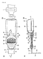
- a buckle device 10a for a seat belt according to a second embodiment shown in Figs. 4 and 5 differs from that of the first embodiment in that tacking is performed on the woven fabric 30.
- the part in which the tucked-in part 31 tucked into the inner side and the front surface part 33 that passes through the hole portion 14 in the anchor plate 11 as a continuation of the tucked-in part 31 overlap is tacked further toward the anchor plate side than the thread 40 using thread 41.
- this buckle device 10a as shown in Fig. 5 , first the tucked-in part 31 of the woven fabric 30 is passed through the hole portion 14 in the anchor plate 11 and folded back at the lower side folded-back part 32, whereupon a part in which the tucked-in part 31 and the front surface part 33 doubly overlap is tacked.
- the rear surface part 35 is then passed through the hole portion 26 in the buckle 20 such that the tip end portion 31a of the overlapping woven fabric 30 comes into contact with the metal plate portion 25 of the buckle 20 and folded back at the upper side folded-back part 34, whereupon the triply overlapped part is sewn.
- the triply overlapped part can be prevented from shifting during sewing by tacking the anchor plate side in cases where it is difficult to sew the overlapping part at one time, such as a case where the overall length of the woven fabric 30 is short, and as a result, the workability of the sewing operation can be improved. Further, the tip end portion 31a of the woven fabric 30, which is tucked into the inner side, can be brought reliably into contact with the buckle 20, and as a result, the rigidity of the woven fabric 30 can be improved.
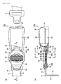
- a buckle device 10b for a seat belt according to a third embodiment shown in Figs. 6 and 7 differs from that of the first embodiment in that resin sheets 50, 51 are interposed from the folded back parts to the overlapping part of the woven fabric 30.
- the resin sheets 50, 51 are constituted by polypropylene or the like having a thickness of approximately 0. 8mm, and are disposed respectively on the anchor plate side and the buckle side of the part that is sewn by the thread 40.
- the anchor plate side sheet 50 is sandwiched between doubled-back parts in which the two width direction edge portions 32a of the lower side folded-back part 32 are doubled back, and extends to the part in which the tucked-in part 31 and the front surface part 33 overlap.
- the buckle side sheet 51 is sandwiched between doubled-back parts in which the two width direction edge portions 34a of the upper side folded-back part 34 are doubled back, and extends to the part in which the tucked-in part 31 and the front surface part 33 overlap.
- the rigidity of a part between the sewn part and the anchor plate 11 or a part between the sewn part and the buckle 20 can be improved. Furthermore, since the sheets 50, 51 are interposed in the woven fabric 30, the sheets 50, 51 do not become dislodged. Moreover, the sheets 50, 51 are hidden from view, and therefore a pleasing outer form can be maintained.
- the sewn part in which the woven fabric 30 is sewn may be divided in the width direction, and a resin sheet 52 may be passed through an intermediate width direction position removed from the sewn part and extended to the vicinity of the respective hole portions 14, 26 in the anchor plate 11 and buckle 20. In so doing, similar effects to those described above can be obtained with the single resin sheet 52.
- a buckle device 10d for a seat belt according to a fourth embodiment shown in Fig. 9 differs from that of the second embodiment in the sewn part where the woven fabric is sewn.
- the woven fabric 30 is sewn in the triply overlapped part up to positions near the doubled-back parts.
- rigidity is secured by increasing the thickness of the woven fabric 30, and in the triply overlapped part between the doubled-back parts on either lengthwise direction side, the sewn part is extended in the lengthwise direction.
- a region of the woven fabric 30 having increased rigidity is enlarged, and the rigidity of the woven fabric 30 is increased over the entire lengthwise direction region.
- a buckle device 10e for a seat belt according to a fifth embodiment shown in Figs. 10 and 11 differs from that of the fourth embodiment in the shape of the part where the woven fabric is sewn.
- the woven fabric 30 is sewn in the triply overlapped part up to positions near the doubled-back parts.
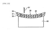
- the overlapping part is sewn such that an arch-shaped cross-section is formed, as shown in Fig. 11(c) .
- a section modulus of the overlapping part is increased, leading to an increase in rigidity.
- the overlapping part may be sewn into this sectional shape by placing the overlapping part on an arch-shaped cradle 60 of a sewing machine and sewing the overlapping part using a sewing needle 61, as shown in Fig. 12 .
- a buckle device 10f for a seat belt according to a sixth embodiment shown in Figs. 13 and 14 differs from that of the fifth embodiment in that a periphery of the woven fabric 30 is covered by a resin member.
- a tube 70 serving as the resin member is introduced from the anchor plate 11 side and attached to the periphery of the woven fabric 30 formed with an arch-shaped cross-section.
- the tube 70 is constituted by a resin material that stretches only slightly, formed such that an inner peripheral length thereof is shorter than a sectional circumference of the woven fabric 30, and adhered to the periphery of the woven fabric 30.
- the arch-shaped cross-section of the woven fabric 30 can be maintained by the tube 70, enabling an improvement in the rigidity of the woven fabric 30.
- resin tape may be wound around the periphery of the woven fabric 30 to maintain the arch-shaped cross-section of the woven fabric 30.
- a buckle device 10g for a seat belt according to a seventh embodiment shown in Figs. 15 to 17 differs from that of the first embodiment in that the woven fabric 30 is sewn when the front surface part 33 is doubled back.
- two width direction edge portions 33a of the front surface part 33 located in the overlapping part of the woven fabric 30 between the folded-back parts 32, 34 passing respectively through the hole portion 26 in the buckle 20 and the hole portion 14 in the anchor plate 11 are doubled back on the inner side toward a width direction intermediate portion.
- the front surface part 33 is passed through one of the hole portions 14, 26, unfolded, and then sewn.
- the front surface part 33 is sewn together with the tucked-in part 31 and the rear surface part 35 while doubled back as described above. Accordingly, as shown by dotted lines in Fig.
- the woven fabric 30 is sewn in a state where the two width direction edge portions 33a of the front surface part 33 are doubled back continuously from the two width direction edge portions 32a, 34a of the upper side and lower side folded-back parts 32, 34.
- a further improvement in the flexural rigidity of the woven fabric 30 can be achieved, and a self-standing property can be secured in the woven fabric 30.
- the woven fabric 30 is sewn in the triply overlapping part up to positions near the doubled back parts 32a, 34a.
- a buckle device 10h for a seat belt according to an eighth embodiment shown in Figs. 18 and 19 differs from that of the seventh embodiment in that an arch-shaped cross-section is formed by cross-stitching.
- the woven fabric 30 is sewn in a state where the two width direction edge portions of the front surface part 33 are doubled back on the inner side toward the width direction intermediate portion (see Fig. 19(a) ). Furthermore, in this embodiment, as shown in Fig. 19(b) , the overlapping part of the woven fabric 30 is placed on an arch-shaped cradle 60 of a sewing machine and cross-stitched using a sewing needle 62 up to positions near the folded-back parts 32, 34 so as to cross a bent part 33b of the front surface part 33 and so as to pass from the tucked-in part 31 back to the tucked-in part 31 via the front surface part 33 in the width direction.
- the doubled-back front surface part 33 is sewn more securely and the section modulus is increased by providing the overlapping part with an arch-shaped cross-section. As a result, a further increase in rigidity can be achieved.
- the part of the woven fabric 30 that passes through the hole portion 26 in the buckle 20 is formed as the tucked-in part 31, the tip end portion 31a of which contacts the anchor plate 11, and a part of the woven fabric 30 on the lower side of the drawings, which passes through the hole portion 14 in the anchor plate 11, is formed as the rear surface part 35. Further, the rear surface part 35 is extended to the vicinity of the hole portion 26 in the buckle 20, thereby improving the rigidity of the woven fabric 30.
- the rear surface part 35 includes a part located in a region extending from a lengthwise direction sewn part to the tip end portion 35a where threads on at least one surface 37 of an inside surface and an outside surface are fixed to each other by hot-melting.
- the tip end portion 35a forms a resin plate, enabling an improvement in the flexural rigidity thereof.
- the rear surface part 35 of the woven fabric 30 is more difficult to fold, and therefore the tucked-in part 31 is passed through the hole portion 14 in the anchor plate 11 and the hole portion 26 in the buckle 20 and then sewn.
- the woven fabric 30 is provided with a selvage for improving texture on a width direction outer side of a strength-receiving warp thread and a catch thread for preventing fraying of a weft thread.
- the part of the woven fabric 30 that passes through the hole portion 14 of the anchor plate 11 may be formed as the tucked-in part 31 that contacts the metal plate portion 25 of the buckle
- the part of the woven fabric 30 that passes through the hole portion 26 of the buckle 20 may be formed as the rear surface part 35
- the rear surface part 35 may be extended to the vicinity of the hole portion 14 in the anchor plate 11.
- the present invention is not limited to the embodiments described above, and may be modified, improved, and so on appropriately. Further, the respective embodiments may be applied in combinations within a feasible scope, and the object of the present invention may be achieved individually by the features of the respective embodiments.
- the second to ninth embodiments preferably include the featured constitution of the first embodiment whereby the tip end portion 31a of the woven fabric 30 that is tucked in on the inner side contacts the buckle 20, but the object of the present invention can be achieved by the features of the second to ninth embodiments regardless of whether or not this feature of the first embodiment is employed.
- the tip end portion 31a of the woven fabric 30 that is tucked in on the inner side contacts the buckle 20, but identical effects can be achieved when the tip end portion 31a contacts the anchor plate 11.
Description
- The present invention relates to a buckle device for a seat belt installed in a side portion of a vehicle seat.
- A three-point seat belt device employing webbing is used as a typical seat belt device for holding a vehicle occupant or the like safely in a seat. In this type of seat belt device, one end portion of the webbing is latched to a retractor and another end portion is latched to a lap anchor fixed to a vehicle body via a through anchor. By engaging a through tongue disposed in an intermediate portion of the webbing between the lap anchor and the through anchor with a buckle device fixed to a vehicle body inner side, the occupant is restrained in the seat.
- The buckle device is normally constituted by an anchor plate that can be attached to the vehicle body side, a buckle to which the tongue of the seat belt can be attached detachably, and a connecting member that connects the anchor plate to the buckle (see
Patent Document 1, for example).
Patent Document 1: Japanese Utility Model Application Publication No.H1-117963 - Incidentally, when a buckle device is used in a rear seat of an automobile, the buckle device preferably possesses a predetermined rigidity that enables the buckle to self-stand relative to the anchor plate but does not cause an obstruction to a boarding/alighting occupant.
- From the
GB 2 391 002 A claim 1. - The present invention has been designed in consideration of the circumstances described above, and an object thereof is to provide a buckle device for a seat belt constituted such that a predetermined rigidity is maintained by a woven fabric that connects a buckle to an anchor plate so that the buckle can be made self-standing, the buckle, despite being self-standing, does not cause an obstruction when an occupant sits down, and an improvement in the seating comfort of the occupant can be achieved.
- The present invention achieves the object described above by means of the following constitutions.
- (1) A buckle device for a seat belt, including:
- an anchor plate that can be attached to a vehicle body side;
- a buckle to which a tongue of the seat belt can be attached detachably; and
- a woven fabric that is passed through hole portions formed respectively in the anchor plate and the buckle and then folded back so as to overlap at least triply,
- wherein the overlapping part includes a tucked-in part that is tucked into an inner side, a front surface part that is folded back from the tucked-in part and forms a continuation at the folded-back part, and a rear surface part that is folded back from said front surface part and forms a continuation at the folded-back part,
- wherein respective edge portions of respective folded-back parts formed by passing the woven fabric through said hole portions formed respectively in the anchor plate and said buckle and then folding said woven fabric back are doubled back on said inner side toward an intermediate portion of a width direction in order to increase a section modulus,
- said woven fabric is sewn in said at least triply overlapped part, and
- obtaining a sufficient rigidity for securing a self-standing property of the buckle,
- wherein a tip end portion of the tucked-in part contacts the opposing buckle or anchor plate.
- (2) The buckle device for a seat belt according to (1) , wherein the tip end portion of the tucked-in part contacts a metal plate portion for forming the hole portion of the buckle.
- (3) The buckle device for a seat belt according to any of (1) or (2), wherein the woven fabric is tacked in a part where the tucked-in part and the front surface part overlap.
- (4) The buckle device for a seat belt according to any of (1) to (3), wherein a resin sheet is interposed from the folded-back parts to the overlapping part.
- (5) The buckle device for a seat belt according to (4), wherein the sewn part is divided in the width direction of the woven fabric, and the resin sheet passes a position that deviates from the sewn part in which the woven fabric is sewn and continues to the vicinity of the respective hole portions of the anchor plate and the buckle.
- (6) The buckle device for a seat belt according to any of (1) to (5), wherein the woven fabric is sewn in the triply overlapped part up to positions near the parts where the respective width direction edge portions are doubled back on the inner side toward the width direction intermediate portion.
- (7) The buckle device for a seat belt according to any of (1) to (6), wherein the overlapping part of the woven fabric is formed with an arch-shaped cross-section.
- (8) The buckle device for a seat belt according to any of (1) to (7), wherein a periphery of the overlapping part of the woven fabric is covered by a resin member.
- (9) The buckle device for a seat belt according to any of (1) to (8), wherein, in the overlapping part, the front surface part between the folded-back parts that pass through the respective hole portions of the buckle and the anchor plate is sewn in a state where the respective width direction edge portions are doubled back on the inner side toward the width direction intermediate portion.
- (10) The buckle device for a seat belt according to (9), wherein the woven fabric is cross-stitched in the width direction so as to cross the tucked-in part from the tucked-in part over the front surface part, and the overlapping part has an arch-shaped cross-section.
- (11) The buckle device for a seat belt according to any of (1) to (10), wherein the rear surface part extends to the vicinity of the hole portion of one of the buckle and the anchor plate.
- (12) The buckle device for a seat belt according to (11), wherein a lengthwise direction tip end portion of the rear surface part is formed by heat cutting into a piping shape having a dimension that is equal to or greater than a thickness of the woven fabric.
- (13) The buckle device for a seat belt according to (11) or (12), wherein the rear surface part includes a part located in a region extending from a lengthwise direction sewn part to the tip end portion where threads on at least one of an inside surface and an outside surface are fixed to each other by hot-melting.
- (14) The buckle device for a seat belt according to any of (11) to (13), wherein threads on an ear portion of the woven fabric are fixed to each other by hot-melting.
- With the buckle device for a seat belt according to the present invention, the woven fabric is passed through the hole portions formed respectively in the anchor plate and the buckle, folded back so as to overlap at least triply, and sewn in the overlapping part. Further, the respective width direction edge portions of the respective folded-back parts folded back by passing the woven fabric through the hole portions formed respectively in the anchor plate and the buckle are doubled back on the inner side toward the width direction intermediate portion. Therefore, a predetermined rigidity can be maintained in the woven fabric over the overlapping part and the folded-back parts, and as a result, a self-standing property can be secured, enabling an improvement in the seating comfort of an occupant.
- Further, the tip end portion of the woven fabric tucked into the inner side is caused to contact the opposing buckle or anchor plate, and therefore a further improvement in rigidity can be achieved by the woven fabric, enabling a further improvement in the seating comfort of the occupant.
- Furthermore, the doubly overlapped part is tacked after passing the woven fabric through one of the hole portions in the anchor plate and the buckle and folding the woven fabric back, the tip end portion of the overlapped woven fabric is caused to contact the other of the anchor plate and the buckle, and in this state, the woven fabric is passed through the other hole portion formed in the anchor plate or the buckle and folded back to form the triply overlapped part, whereupon the triply overlapped part is sewn. Thus, the overlapping part can be prevented from shifting during sewing and the tip end portion of the woven fabric tucked into the inner side can be brought into contact with the anchor plate or the buckle reliably, leading to improvements in the workability of the sewing operation and the rigidity of the woven fabric.
- Moreover, in the overlapping part, the front surface part between the two hole portions, which is formed by passing the woven fabric through one of the hole portions in the buckle and the anchor plate, is sewn in a state where the respective width direction edge portions thereof are doubled back on the inner side toward the width direction intermediate portion, and therefore the flexural rigidity of the woven fabric can be improved. As a result, the self-standing property of the woven fabric can be secured.
-
-
Fig. 1 shows a buckle device for a seat belt according to a first embodiment of the present invention, whereinFig. 1(a) is a front view andFig. 1(b) is a side view; -
Fig. 2(a) is a sectional view taken along a II-II line inFig. 1 (a) ,Fig. 2 (b) is a sectional view taken along a II' -II' line inFig. 1 (b) , andFig. 2 (c) is a sectional view taken along a II"-II" line inFig. 1(b) ; -
Fig. 3 is an expanded view of a woven fabric shown inFig. 1 ; -
Fig. 4 shows a buckle device for a seat belt according to a second embodiment of the present invention, whereinFig. 4(a) is a front view andFig. 4(b) is a side view; -
Fig. 5 shows a process for tacking the buckle device ofFig. 4 , whereinFig. 5(a) is a principal front view andFig. 5(b) is a principal side view; -
Fig. 6 shows a buckle device for a seat belt according to a third embodiment of the present invention, whereinFig. 6(a) is a front view andFig. 6(b) is a side view; -
Fig. 7 (a) is a sectional view taken along a VII-VII line inFig. 6(a) ,Fig. 7(b) is a sectional view taken along a VII'-VII' line inFig. 6(b) , andFig. 7(c) is a sectional view taken along a VII" -VII" line inFig. 6(b) ; -
Fig. 8 shows a buckle device for a seat belt according to a modified example of the third embodiment of the present invention, whereinFig. 8(a) is a front view andFig. 8(b) is a sectional view taken along an VIII-VIII line inFig. 8(a) ; -
Fig. 9 shows a buckle device for a seat belt according to a modified example of a fourth embodiment of the present invention, whereinFig. 9(a) is a front view andFig. 9(b) is a sectional view taken along a IX-IX line inFig. 9(a) ; -
Fig. 10 shows a buckle device for a seat belt according to a fifth embodiment of the present invention, whereinFig. 10(a) is a front view andFig. 10(b) is a sectional view taken along a X-X line inFig. 10(a) ; -
Fig. 11(a) is a sectional view taken along an XI-XI line inFig. 10(b) ,Fig. 11(b) is a sectional view taken along an XI'-XI' line inFig. 10(b) , andFig. 11(c) is a sectional view taken along an XI"-XI" line inFig. 10(b) ; -
Fig. 12 is a view showing a woven fabric ofFig. 10 in a sewn state; -
Fig. 13 shows a buckle device for a seat belt according to a sixth embodiment of the present invention, whereinFig. 13 (a) is a front view andFig. 13 (b) is a sectional view taken along a XIII-XIII line inFig. 13(a) ; -
Fig. 14 (a) is a sectional view taken along a XIV-XIV line inFig. 13(b) ,Fig. 14(b) is a sectional view taken along a XIV' -XIV' line inFig. 13 (b) , andFig. 14 (c) is a sectional view taken along a XIV"-XIV" line inFig. 13(b) ; -
Fig. 15 shows a buckle device for a seat belt according to a seventh embodiment of the present invention, whereinFig. 15 (a) is a front view andFig. 15 (b) is a sectional view taken along a XV-XV line inFig. 15(a) ; -
Fig. 16(a) is a sectional view taken along a XV-XV line inFig. 15(b) ,Fig. 16(b) is a sectional view taken along a XV'-XV' line inFig. 15(b) , andFig. 16(c) is a sectional view taken along a XV"-XV" line inFig. 15(b) ; -
Fig. 17 is an expanded view of a woven fabric shown inFig. 15 ; -
Fig. 18 shows a buckle device for a seat belt according to an eighth embodiment of the present invention, whereinFig. 18 (a) is a front view andFig. 18 (b) is a sectional view taken along an XVIII-XVIII line inFig. 18(a) ; -
Fig. 19(a) shows a state prior to cross-stitching of a woven fabric shown inFig. 18 , andFig. 19(b) is a view showing a state during cross-stitching; -
Fig. 20 shows a buckle device for a seat belt according to a ninth embodiment of the present invention, whereinFig. 20 (a) is a front view andFig. 20 (b) is a sectional view taken along a XX-XX line inFig. 20(a) ; -
Fig. 21 (a) is a sectional view taken along a XXI-XXI line inFig. 20(b) ,Fig. 21(b) is a sectional view taken along a XXI'-XXI' line inFig. 20(b) , andFig. 21(c) is a sectional view taken along a XXI"-XXI" line inFig. 20(b) ; and -
Fig. 22 is an expanded view of a woven fabric shown inFig. 20 . -
- 10
- buckle device
- 11
- anchor plate
- 14
- hole portion
- 20
- buckle
- 26
- hole portion
- 30
- woven fabric
- 31
- tucked-in part
- 33
- front surface part
- 35
- rear surface part
- 40
- thread
- Examples of a buckle device for a seat belt and a manufacturing method thereof according to embodiments of the present invention will be described in detail below with reference to the drawings.
- As shown in
Figs. 1 to 3 , abuckle device 10 for a seat belt according to a first embodiment of the present invention includes ananchor plate 11 that can be attached to a vehicle body side, abuckle 20 to which atongue 1 of the seat belt can be attached detachably, and a strip-form wovenfabric 30 that connects theanchor plate 11 to thebuckle 20. - The
anchor plate 11 is formed substantially in an L-shape and includes aplanar portion 13 that is fastened by a bolt (not shown) to a floor surface on the vehicle body side by inserting the bolt into afastening hole 12, and anupright portion 15 that is bent from theplanar portion 13 and formed with ahole portion 14 in an end portion thereof. - A
tongue insertion portion 21 is provided on one end side of thebuckle 20, and ahole portion 26 is formed on another end side by laying ametal plate portion 25 in a width direction across arecess portion 24 formed by a pair of resin covers 22, 23. - The woven
fabric 30 is passed through thehole portions anchor plate 11 and buckle, folded back, and then sewn in a triply overlappedpart using thread 40. As shown inFig. 3 , the wovenfabric 30 is formed from webbing having a constant width, which is cut into a predetermined length and chamfered on all four corners, and includes a tucked-inpart 31 that is tucked into an inner side when the wovenfabric 30 is overlapped, a lower side folded-back part 32 that is folded back at thehole portion 14 of theanchor plate 11, afront surface part 33 that forms a continuation of the tucked-inpart 31 via the lower side folded-back part 32, an upper side folded-back part 34 that is folded back at thehole portion 26 of thebuckle 20, and arear surface part 35 that forms a continuation of the upper side folded-back part 34 and sandwiches the tucked-inpart 31 together with thefront surface part 33. In other words, the wovenfabric 30 has a substantially uniform width from the tucked-inpart 31 to therear surface part 35, excluding the four corners. - As shown in
Figs. 2(a) and 2(b) , respective widthdirection edge portions back parts hole portions anchor plate 11 and thebuckle 20 are doubled back on the inner side toward a width direction intermediate portion in order to increase a section modulus of theseparts part 31,front surface part 33 andrear surface part 35 are chamfered on both lengthwise direction sides so as to have a greater width than the lower side and upper folded-back parts Fig. 1(a) , theanchor plate 11 and thebuckle 20 are connected. - As shown in
Fig. 2 (a) , in the wovenfabric 30 sewn in this manner, atip end portion 31a of the tucked-inpart 31 tucked into the inner side has a substantially identical width to the front surface andrear surface parts metal plate portion 25 of thebuckle 20. Thus, a predetermined rigidity is maintained in thebuckle device 10 by the wovenfabric 30, and as a result, a self-standing property of thebuckle 20 and the seating comfort of an occupant can be improved. - Further, the woven
fabric 30 includes the overlapping part that is folded back through thehole portions anchor plate 11 andbuckle 20 and sewn in the triply overlapped part, and the two widthdirection edge portions respective hole portions anchor plate 11 andbuckle 20. The wovenfabric 30 is sewn in at least the triply overlapping part, and the sewn part is provided up to the vicinity of the width direction end portion of the wovenfabric 30. With the two doubled-back end portions fabric 30, sufficient rigidity for securing a self-standing property in thebuckle 20 is obtained while preventing thebuckle 20 from causing an obstruction when the occupant sits down. - Note that mutually contacting surfaces of the woven
fabric 30, or more specifically theedge portions back parts end portion 35a of therear surface part 35 contacts the tucked-inpart 31, and so on are joined by adhesion or the like. - Further, during manufacture of the
buckle device 10, the respective folded-back parts front surface part 33 and one of the tucked-inpart 31 and therear surface part 35 of the wovenfabric 30 are passed through therespective hole portions part 31 and therear surface part 35 as is. Then, with the widthdirection edge portions back parts front surface part 33 and one of the tucked-inpart 31 and therear surface part 35 are unfolded, whereupon the at least triply overlappedpart - Alternatively, the respective folded-
back parts part 31 and therear surface part 35 of the wovenfabric 30 are passed through therespective hole portions front surface part 33 as is. Then, with the widthdirection edge portions back parts part 31 and therear surface part 35 are unfolded, whereupon the at least triply overlappedpart - A
buckle device 10a for a seat belt according to a second embodiment shown inFigs. 4 and5 differs from that of the first embodiment in that tacking is performed on the wovenfabric 30. - More specifically, in the woven
fabric 30, the part in which the tucked-inpart 31 tucked into the inner side and thefront surface part 33 that passes through thehole portion 14 in theanchor plate 11 as a continuation of the tucked-inpart 31 overlap is tacked further toward the anchor plate side than thethread 40 usingthread 41. - Hence, in this
buckle device 10a, as shown inFig. 5 , first the tucked-inpart 31 of the wovenfabric 30 is passed through thehole portion 14 in theanchor plate 11 and folded back at the lower side folded-back part 32, whereupon a part in which the tucked-inpart 31 and thefront surface part 33 doubly overlap is tacked. Therear surface part 35 is then passed through thehole portion 26 in thebuckle 20 such that thetip end portion 31a of the overlapping wovenfabric 30 comes into contact with themetal plate portion 25 of thebuckle 20 and folded back at the upper side folded-back part 34, whereupon the triply overlapped part is sewn. - When tacking is performed in this manner, the triply overlapped part can be prevented from shifting during sewing by tacking the anchor plate side in cases where it is difficult to sew the overlapping part at one time, such as a case where the overall length of the woven
fabric 30 is short, and as a result, the workability of the sewing operation can be improved. Further, thetip end portion 31a of the wovenfabric 30, which is tucked into the inner side, can be brought reliably into contact with thebuckle 20, and as a result, the rigidity of the wovenfabric 30 can be improved. - Note that all other constitutions and actions are identical to those of the first embodiment.
- A
buckle device 10b for a seat belt according to a third embodiment shown inFigs. 6 and7 differs from that of the first embodiment in thatresin sheets fabric 30. - More specifically, in this example the
resin sheets thread 40. The anchorplate side sheet 50 is sandwiched between doubled-back parts in which the two widthdirection edge portions 32a of the lower side folded-back part 32 are doubled back, and extends to the part in which the tucked-inpart 31 and thefront surface part 33 overlap. Likewise, thebuckle side sheet 51 is sandwiched between doubled-back parts in which the two widthdirection edge portions 34a of the upper side folded-back part 34 are doubled back, and extends to the part in which the tucked-inpart 31 and thefront surface part 33 overlap. By interposing theresin sheets fabric 30 in this manner, the rigidity of a part between the sewn part and theanchor plate 11 or a part between the sewn part and thebuckle 20 can be improved. Furthermore, since thesheets fabric 30, thesheets sheets - All other constitutions and actions are identical to those of the first embodiment.
- As illustrated by a
seat belt device 10c according to a modified example shown inFig. 8 , the sewn part in which the wovenfabric 30 is sewn may be divided in the width direction, and aresin sheet 52 may be passed through an intermediate width direction position removed from the sewn part and extended to the vicinity of therespective hole portions anchor plate 11 andbuckle 20. In so doing, similar effects to those described above can be obtained with thesingle resin sheet 52. - A
buckle device 10d for a seat belt according to a fourth embodiment shown inFig. 9 differs from that of the second embodiment in the sewn part where the woven fabric is sewn. - More specifically, the woven
fabric 30 is sewn in the triply overlapped part up to positions near the doubled-back parts. In the parts where the two widthdirection edge portions respective hole portions anchor plate 11 andbuckle 20, rigidity is secured by increasing the thickness of the wovenfabric 30, and in the triply overlapped part between the doubled-back parts on either lengthwise direction side, the sewn part is extended in the lengthwise direction. Hence, a region of the wovenfabric 30 having increased rigidity is enlarged, and the rigidity of the wovenfabric 30 is increased over the entire lengthwise direction region. - Note that all other constitutions and actions are identical to those of the second embodiment.
- A
buckle device 10e for a seat belt according to a fifth embodiment shown inFigs. 10 and11 differs from that of the fourth embodiment in the shape of the part where the woven fabric is sewn. - In this embodiment also, the woven
fabric 30 is sewn in the triply overlapped part up to positions near the doubled-back parts. However, the overlapping part is sewn such that an arch-shaped cross-section is formed, as shown inFig. 11(c) . With this sectional shape, a section modulus of the overlapping part is increased, leading to an increase in rigidity. The overlapping part may be sewn into this sectional shape by placing the overlapping part on an arch-shapedcradle 60 of a sewing machine and sewing the overlapping part using asewing needle 61, as shown inFig. 12 . - All other constitutions and actions are identical to those of the fourth embodiment.
- A
buckle device 10f for a seat belt according to a sixth embodiment shown inFigs. 13 and14 differs from that of the fifth embodiment in that a periphery of the wovenfabric 30 is covered by a resin member. - More specifically, in this embodiment, a
tube 70 serving as the resin member is introduced from theanchor plate 11 side and attached to the periphery of the wovenfabric 30 formed with an arch-shaped cross-section. Thetube 70 is constituted by a resin material that stretches only slightly, formed such that an inner peripheral length thereof is shorter than a sectional circumference of the wovenfabric 30, and adhered to the periphery of the wovenfabric 30. Thus, the arch-shaped cross-section of the wovenfabric 30 can be maintained by thetube 70, enabling an improvement in the rigidity of the wovenfabric 30. - All other constitutions and actions are identical to those of the fifth embodiment. Note that instead of using the
tube 70 as the resin member, resin tape may be wound around the periphery of the wovenfabric 30 to maintain the arch-shaped cross-section of the wovenfabric 30. - A
buckle device 10g for a seat belt according to a seventh embodiment shown inFigs. 15 to 17 differs from that of the first embodiment in that the wovenfabric 30 is sewn when thefront surface part 33 is doubled back. - More specifically, in the embodiments described above, including this embodiment, two width
direction edge portions 33a of thefront surface part 33 located in the overlapping part of the wovenfabric 30 between the folded-back parts hole portion 26 in thebuckle 20 and thehole portion 14 in theanchor plate 11 are doubled back on the inner side toward a width direction intermediate portion. In the embodiments described above, thefront surface part 33 is passed through one of thehole portions front surface part 33 is sewn together with the tucked-inpart 31 and therear surface part 35 while doubled back as described above. Accordingly, as shown by dotted lines inFig. 17 , the wovenfabric 30 is sewn in a state where the two widthdirection edge portions 33a of thefront surface part 33 are doubled back continuously from the two widthdirection edge portions back parts fabric 30 can be achieved, and a self-standing property can be secured in the wovenfabric 30. Note that in this embodiment, similarly to the fourth embodiment, the wovenfabric 30 is sewn in the triply overlapping part up to positions near the doubled backparts - All other constitutions and actions are identical to those of the first embodiment.
- A
buckle device 10h for a seat belt according to an eighth embodiment shown inFigs. 18 and19 differs from that of the seventh embodiment in that an arch-shaped cross-section is formed by cross-stitching. - More specifically, similarly to the seventh embodiment, the woven
fabric 30 is sewn in a state where the two width direction edge portions of thefront surface part 33 are doubled back on the inner side toward the width direction intermediate portion (seeFig. 19(a) ). Furthermore, in this embodiment, as shown inFig. 19(b) , the overlapping part of the wovenfabric 30 is placed on an arch-shapedcradle 60 of a sewing machine and cross-stitched using a sewing needle 62 up to positions near the folded-back parts bent part 33b of thefront surface part 33 and so as to pass from the tucked-inpart 31 back to the tucked-inpart 31 via thefront surface part 33 in the width direction. Hence, in this embodiment, the doubled-backfront surface part 33 is sewn more securely and the section modulus is increased by providing the overlapping part with an arch-shaped cross-section. As a result, a further increase in rigidity can be achieved. - All other constitutions and actions are identical to those of the seventh embodiment.
- In a
buckle device 10i for a seat belt according to a ninth embodiment shown inFigs. 20 to 22 , the part of the wovenfabric 30 that passes through thehole portion 26 in thebuckle 20 is formed as the tucked-inpart 31, thetip end portion 31a of which contacts theanchor plate 11, and a part of the wovenfabric 30 on the lower side of the drawings, which passes through thehole portion 14 in theanchor plate 11, is formed as therear surface part 35. Further, therear surface part 35 is extended to the vicinity of thehole portion 26 in thebuckle 20, thereby improving the rigidity of the wovenfabric 30. - Further, a lengthwise direction
tip end portion 35a of therear surface part 35 of the wovenfabric 30, which is constituted by a pair of inclined portions 35a1 and an intermediate portion 35a2 located between the inclined portions 35al, is melted slightly excessively during heat cutting so as to be formed into a piping shape having a dimension that is equal to or greater than the thickness of the wovenfabric 30, and as a result, the rigidity of a tip end portion 36 is increased. Furthermore, therear surface part 35 includes a part located in a region extending from a lengthwise direction sewn part to thetip end portion 35a where threads on at least onesurface 37 of an inside surface and an outside surface are fixed to each other by hot-melting. As a result, thetip end portion 35a forms a resin plate, enabling an improvement in the flexural rigidity thereof. In this case, therear surface part 35 of the wovenfabric 30 is more difficult to fold, and therefore the tucked-inpart 31 is passed through thehole portion 14 in theanchor plate 11 and thehole portion 26 in thebuckle 20 and then sewn. - Further, the woven
fabric 30 is provided with a selvage for improving texture on a width direction outer side of a strength-receiving warp thread and a catch thread for preventing fraying of a weft thread. By fixing the threads on anear portion 38 of the wovenfabric 30 through hot-melting, an overall improvement in rigidity can be achieved without affecting the strength and fraying prevention property. - All other constitutions and actions are identical to those of the seventh embodiment. Note that similarly to the embodiments described above, the part of the woven
fabric 30 that passes through thehole portion 14 of theanchor plate 11 may be formed as the tucked-inpart 31 that contacts themetal plate portion 25 of the buckle, the part of the wovenfabric 30 that passes through thehole portion 26 of thebuckle 20 may be formed as therear surface part 35, and therear surface part 35 may be extended to the vicinity of thehole portion 14 in theanchor plate 11. - The present invention is not limited to the embodiments described above, and may be modified, improved, and so on appropriately. Further, the respective embodiments may be applied in combinations within a feasible scope, and the object of the present invention may be achieved individually by the features of the respective embodiments.
- For example, the second to ninth embodiments preferably include the featured constitution of the first embodiment whereby the
tip end portion 31a of the wovenfabric 30 that is tucked in on the inner side contacts thebuckle 20, but the object of the present invention can be achieved by the features of the second to ninth embodiments regardless of whether or not this feature of the first embodiment is employed. - Furthermore, in the embodiments described above, the
tip end portion 31a of the wovenfabric 30 that is tucked in on the inner side contacts thebuckle 20, but identical effects can be achieved when thetip end portion 31a contacts theanchor plate 11.
Claims (14)
- A buckle device (10) for a seat belt, comprising:an anchor plate (11) that can be attached to a vehicle body side;a buckle (20) to which a tongue of said seat belt can be attached detachably; anda woven fabric (30) that is passed through hole portions (14,26) formed respectively in said anchor plate (11) and said buckle (20) and then folded back in folded-back parts (32, 34) so as to overlap at least triply,wherein said overlapping part includes a tucked-in part (31) that is tucked into an inner side, a front surface part (33) that is folded back from said tucked-in part (31) and forms a continuation at the folded-back part (32), and a rear surface part (35) that is folded back from said front surface part (33) and forms a continuation at the folded-back part (34),wherein respective edge portions (32a, 34a) of respective folded-back parts (32, 34) formed by passing said woven fabric through said hole portions formed respectively in said anchor plate and said buckle and then folding said woven fabric back are doubled back on said inner side toward an intermediate portion of a width direction in order to increase a section modulus,said woven fabric (30) is sewn in said at least triply overlapped part, andobtaining a sufficient rigidity for securing a self-standing property of the buckle,characterized in thata tip end portion (31a) of said tucked-in part (31) contacts said opposing buckle (20) or anchor plate (11).
- The buckle device for a seat belt according to claim 1, characterized in that said tip end portion (31a) of said tucked-in part (31) contacts a metal plate portion for forming said hole portion (26) of said buckle (20).
- The buckle device for a seat belt according to any of claims 1 or 2, characterized in that said woven fabric (30) is tacked in a part where said tucked-in part (31) and said front surface part (33) overlap.
- The buckle device for a seat belt according to any of claims 1 to 3, characterized in that a resin sheet (50,51,52) is interposed from said folded-back parts (32,34) to said overlapping part.
- The buckle device for a seat belt according to claim 4, characterized in that said sewn part is divided in said width direction of said woven fabric (30), and said resin sheet (52) passes a position that deviates from said sewn part in which said woven fabric (30) is sewn and continues to the vicinity of said respective hole portions (14,26) of said anchor plate (11) and said buckle (20).
- The buckle device for a seat belt according to any of claims 1 to 5, characterized in that said woven fabric (30) is sewn in said triply overlapped part up to positions near said parts where said respective edge portions (32a, 34a) are doubled back on said inner side toward said width direction intermediate portion.
- The buckle device for a seat belt according to any of claims 1 to 6, characterized in that said overlapping part of said woven fabric (30) is formed with an arch-shaped cross-section.
- The buckle device for a seat belt according to any of claims 1 to 7, characterized in that a periphery of said overlapping part of said woven fabric (30) is covered by a resin member.
- The buckle device for a seat belt according to any of claims 1 to 8, characterized in that in said overlapping part, said front surface part (33) between said folded-back parts (32, 34) that pass through said respective hole portions (14, 26) 2 of said buckle (20) and said anchor plate (11) is sewn in a state where said respective edge portions (32a, 34a) are doubled back on said inner side toward said width direction intermediate portion.
- The buckle device for a seat belt according to claim 9, characterized in that said woven fabric (30) is cross-stitched in said width direction so as to cross said tucked-in part (31) from said tucked-in part (31) over said front surface part (33), and said overlapping part has an arch-shaped cross-section.
- The buckle device for a seat belt according to any of claims 1 to 10, characterized in that said rear surface part (35) extends to the vicinity of said hole portion (14,26) of one of said buckle (20) and said anchor plate (11).
- The buckle device for a seat belt according to claim 11, characterized in that a lengthwise direction tip end portion (35a) of said rear surface part (35) is formed by heat cutting into a piping shape having a dimension that is equal to or greater than a thickness of said woven fabric (30).
- The buckle device for a seat belt according to claim 11 or 12, characterized in that said rear surface part (35) includes a part located in a region extending from a lengthwise direction sewn part to said tip end portion (35a) where threads on at least one of an inside surface and an outside surface are fixed to each other by hot-melting.
- The buckle device for a seat belt according to any of claims 11 to 13, characterized in that threads on an ear portion (38) of said woven fabric (30) are fixed to each other by hot-melting.
Priority Applications (2)
| Application Number | Priority Date | Filing Date | Title |
|---|---|---|---|
| EP12171137.8A EP2511142B1 (en) | 2007-09-11 | 2008-09-11 | Buckle device for seat belt |
| EP12171148.5A EP2505437B1 (en) | 2007-09-11 | 2008-09-11 | Buckle device for seat belt |
Applications Claiming Priority (2)
| Application Number | Priority Date | Filing Date | Title |
|---|---|---|---|
| JP2007235456 | 2007-09-11 | ||
| PCT/JP2008/066388 WO2009035022A1 (en) | 2007-09-11 | 2008-09-11 | Buckle device for seatbelt and method of manufacturing the same |
Related Child Applications (4)
| Application Number | Title | Priority Date | Filing Date |
|---|---|---|---|
| EP12171148.5A Division EP2505437B1 (en) | 2007-09-11 | 2008-09-11 | Buckle device for seat belt |
| EP12171148.5A Division-Into EP2505437B1 (en) | 2007-09-11 | 2008-09-11 | Buckle device for seat belt |
| EP12171137.8A Division EP2511142B1 (en) | 2007-09-11 | 2008-09-11 | Buckle device for seat belt |
| EP12171137.8A Division-Into EP2511142B1 (en) | 2007-09-11 | 2008-09-11 | Buckle device for seat belt |
Publications (3)
| Publication Number | Publication Date |
|---|---|
| EP2199159A1 EP2199159A1 (en) | 2010-06-23 |
| EP2199159A4 EP2199159A4 (en) | 2011-11-30 |
| EP2199159B1 true EP2199159B1 (en) | 2014-07-16 |
Family
ID=40452029
Family Applications (3)
| Application Number | Title | Priority Date | Filing Date |
|---|---|---|---|
| EP08830977.8A Active EP2199159B1 (en) | 2007-09-11 | 2008-09-11 | Buckle device for seatbelt and method of manufacturing the same |
| EP12171137.8A Active EP2511142B1 (en) | 2007-09-11 | 2008-09-11 | Buckle device for seat belt |
| EP12171148.5A Active EP2505437B1 (en) | 2007-09-11 | 2008-09-11 | Buckle device for seat belt |
Family Applications After (2)
| Application Number | Title | Priority Date | Filing Date |
|---|---|---|---|
| EP12171137.8A Active EP2511142B1 (en) | 2007-09-11 | 2008-09-11 | Buckle device for seat belt |
| EP12171148.5A Active EP2505437B1 (en) | 2007-09-11 | 2008-09-11 | Buckle device for seat belt |
Country Status (5)
| Country | Link |
|---|---|
| US (1) | US8650721B2 (en) |
| EP (3) | EP2199159B1 (en) |
| JP (1) | JP5233036B2 (en) |
| CN (4) | CN102632859B (en) |
| WO (1) | WO2009035022A1 (en) |
Families Citing this family (13)
| Publication number | Priority date | Publication date | Assignee | Title |
|---|---|---|---|---|
| WO2009035022A1 (en) | 2007-09-11 | 2009-03-19 | Autoliv Development Ab | Buckle device for seatbelt and method of manufacturing the same |
| GB2471090A (en) * | 2009-06-16 | 2010-12-22 | Autoliv Dev | A connector arrangement |
| DE102012000202B4 (en) * | 2012-01-09 | 2022-08-18 | Zf Automotive Germany Gmbh | Device for anchoring a belt buckle and device arrangement with at least two such devices |
| CN103111836B (en) * | 2013-03-07 | 2016-02-17 | 上海天合汽车安全系统有限公司 | A kind of spring leaf assembly system |
| US9586558B2 (en) * | 2013-10-30 | 2017-03-07 | GM Global Technology Operations LLC | Buckle assembly for a vehicle |
| WO2016040600A1 (en) * | 2014-09-10 | 2016-03-17 | Zodiac Seats Us Llc | Seat belt twist link |
| US20160311396A1 (en) * | 2015-04-24 | 2016-10-27 | GM Global Technology Operations LLC | Belt buckle anchor for thin seats |
| CN106555279B (en) * | 2015-09-25 | 2022-05-31 | 东莞市春藤实业有限公司 | Automatic fastener assembling line turning equipment |
| CN105533964B (en) * | 2016-02-06 | 2017-07-11 | 芊茂(浙江)拉链有限公司 | The case and bag suture processing method of two-way correspondence bond-allocating open end zipper and the case and bag structure for configuring dual-end slide fastener |
| TWI616152B (en) * | 2016-02-18 | 2018-03-01 | Gnmo Zipper Corp | Case stitching processing method for two-way corresponding positioning configuration open zipper and luggage structure for configuring double-end open zipper |
| DE102017118756A1 (en) * | 2017-08-17 | 2019-02-21 | Trw Automotive Gmbh | Belt retractor and method for manufacturing a belt retractor |
| US11285911B2 (en) * | 2020-02-25 | 2022-03-29 | Volvo Car Corporation | Vehicle seat belt assembly |
| CN111546643B (en) * | 2020-03-27 | 2022-02-01 | 平湖尚珠体育用品有限公司 | Full-automatic ultrasonic welding machine |
Citations (1)
| Publication number | Priority date | Publication date | Assignee | Title |
|---|---|---|---|---|
| GB2391002A (en) * | 2002-07-19 | 2004-01-28 | Autoliv Dev | Seat belt buckle assembly |
Family Cites Families (25)
| Publication number | Priority date | Publication date | Assignee | Title |
|---|---|---|---|---|
| US4103933A (en) * | 1976-01-12 | 1978-08-01 | Robert C. Fisher | Floor anchor for seat belt |
| JPS5621412Y2 (en) * | 1976-06-08 | 1981-05-20 | ||
| JPS5820661U (en) * | 1981-07-31 | 1983-02-08 | 松岡 喜一郎 | Cleaner using liquid-vapor mixing nozzle |
| JPS59127652U (en) * | 1983-02-14 | 1984-08-28 | 本田技研工業株式会社 | Seatbelt holding boots for seatbelt attachment aids |
| JPS6185551U (en) * | 1984-11-12 | 1986-06-05 | ||
| JPS61121742U (en) * | 1985-01-18 | 1986-07-31 | ||
| JPH056210Y2 (en) * | 1985-07-06 | 1993-02-17 | ||
| JPS6211055A (en) | 1985-07-09 | 1987-01-20 | Nikko Seiki Kk | Production apparatus of folded confectionery |
| JPS6325669A (en) | 1986-07-18 | 1988-02-03 | Canon Inc | Developing device |
| JPS6325669U (en) * | 1986-08-05 | 1988-02-19 | ||
| JPS6328056U (en) * | 1986-08-07 | 1988-02-24 | ||
| JPH01117963A (en) | 1987-10-30 | 1989-05-10 | Mazda Motor Corp | Idling engine speed controller for engine |
| JPH01117963U (en) | 1988-02-04 | 1989-08-09 | ||
| DE68908199T2 (en) * | 1988-02-08 | 1994-03-17 | Nippon Seiko Kk | Web for fastening a seat belt buckle. |
| JP2949724B2 (en) | 1989-07-11 | 1999-09-20 | 日本電気株式会社 | Semiconductor substrate storage container |
| JPH0735800Y2 (en) * | 1989-08-03 | 1995-08-16 | 日本精工株式会社 | Buckle stokes for seat belts |
| JPH0732284Y2 (en) * | 1989-09-08 | 1995-07-26 | 本田技研工業株式会社 | Seat belt end self-supporting mechanism |
| DE19530445C2 (en) * | 1995-08-18 | 1998-02-26 | Mc Micro Compact Car Ag | Belt buckle holder made of stiffened webbing for a seat belt in a motor vehicle |
| EP1546668A4 (en) * | 2002-07-10 | 2008-01-02 | Automotive Systems Lab | Method of attaching a seat belt to a seat belt tension sensor |
| EP1557327A1 (en) * | 2004-01-21 | 2005-07-27 | Key Safety Systems, Inc. | Buckle assembly |
| WO2006076541A2 (en) * | 2005-01-13 | 2006-07-20 | Takata Seat Belts, Inc. | Buckle support assembly and manufacturing method and system |
| JP4381997B2 (en) * | 2005-02-04 | 2009-12-09 | 株式会社東海理化電機製作所 | Buckle device |
| US7383620B2 (en) * | 2005-05-11 | 2008-06-10 | Takata Seat Belts, Inc. | Buckle support assembly |
| JP4987322B2 (en) | 2006-02-28 | 2012-07-25 | 株式会社東芝 | Moving picture decoding apparatus and moving picture decoding method |
| WO2009035022A1 (en) | 2007-09-11 | 2009-03-19 | Autoliv Development Ab | Buckle device for seatbelt and method of manufacturing the same |
-
2008
- 2008-09-11 WO PCT/JP2008/066388 patent/WO2009035022A1/en active Application Filing
- 2008-09-11 EP EP08830977.8A patent/EP2199159B1/en active Active
- 2008-09-11 CN CN201210083113.3A patent/CN102632859B/en active Active
- 2008-09-11 CN CN201210083114.8A patent/CN102632860B/en active Active
- 2008-09-11 EP EP12171137.8A patent/EP2511142B1/en active Active
- 2008-09-11 JP JP2009532208A patent/JP5233036B2/en active Active
- 2008-09-11 CN CN2008801062351A patent/CN101801738B/en active Active
- 2008-09-11 CN CN201210083115.2A patent/CN102632861B/en active Active
- 2008-09-11 EP EP12171148.5A patent/EP2505437B1/en active Active
- 2008-09-11 US US12/676,800 patent/US8650721B2/en active Active
Patent Citations (1)
| Publication number | Priority date | Publication date | Assignee | Title |
|---|---|---|---|---|
| GB2391002A (en) * | 2002-07-19 | 2004-01-28 | Autoliv Dev | Seat belt buckle assembly |
Also Published As
| Publication number | Publication date |
|---|---|
| US8650721B2 (en) | 2014-02-18 |
| CN102632861B (en) | 2015-02-04 |
| CN102632860A (en) | 2012-08-15 |
| WO2009035022A1 (en) | 2009-03-19 |
| CN102632861A (en) | 2012-08-15 |
| EP2505437B1 (en) | 2015-04-15 |
| JPWO2009035022A1 (en) | 2010-12-24 |
| CN101801738A (en) | 2010-08-11 |
| CN102632859B (en) | 2014-09-03 |
| CN102632859A (en) | 2012-08-15 |
| EP2199159A4 (en) | 2011-11-30 |
| CN101801738B (en) | 2012-06-13 |
| EP2511142A3 (en) | 2012-11-21 |
| CN102632860B (en) | 2015-02-04 |
| EP2199159A1 (en) | 2010-06-23 |
| EP2505437A2 (en) | 2012-10-03 |
| US20100257708A1 (en) | 2010-10-14 |
| EP2511142A2 (en) | 2012-10-17 |
| EP2511142B1 (en) | 2014-04-30 |
| EP2505437A3 (en) | 2012-11-21 |
| JP5233036B2 (en) | 2013-07-10 |
Similar Documents
| Publication | Publication Date | Title |
|---|---|---|
| EP2199159B1 (en) | Buckle device for seatbelt and method of manufacturing the same | |
| US6224089B1 (en) | Connecting structure between an airbag and an inflator | |
| US6439597B1 (en) | Seat provided with side air bag system | |
| US6357789B1 (en) | Seat provided with side air bag system | |
| US7845734B2 (en) | Vehicle seatbelt | |
| US4588208A (en) | Safety belt | |
| US7882605B2 (en) | Fastening element for end areas of garments to be fastened to one another | |
| EP0933263A2 (en) | Air belt device | |
| TWI546024B (en) | Zipper-attached items and zipper-attached articles, and chain and zipper | |
| US20020038950A1 (en) | Method of forming airbag with gas preventing joining portion | |
| JP3188227B2 (en) | Vehicle seat safety belt | |
| WO1999015375A1 (en) | Seat mounted airbag with deployment force concentrator | |
| JP5446657B2 (en) | Air belt and air belt device | |
| US20010002765A1 (en) | Seat belt storing structure | |
| US20080061620A1 (en) | Seatbelt assembly for improved belt safety and comfort | |
| JP4432383B2 (en) | Seat cover structure | |
| JP3723341B2 (en) | Vehicle seat cover mounting structure | |
| CN218172053U (en) | Self-locking type safety belt protection pad | |
| US11535191B2 (en) | Seatbelt assembly with enhanced shoulder belt positioning | |
| JP7130576B2 (en) | Trim covers and vehicle interior parts | |
| JP4068823B2 (en) | Attachment part structure between buckle body and lower attachment and manufacturing method thereof | |
| JP2024027474A (en) | Occupant protection device | |
| JPH05229393A (en) | Air bag body of air bag device | |
| JP3174295B2 (en) | belt | |
| JPH057885Y2 (en) |
Legal Events
| Date | Code | Title | Description |
|---|---|---|---|
| PUAI | Public reference made under article 153(3) epc to a published international application that has entered the european phase |
Free format text: ORIGINAL CODE: 0009012 |
|
| 17P | Request for examination filed |
Effective date: 20100408 |
|
| AK | Designated contracting states |
Kind code of ref document: A1 Designated state(s): AT BE BG CH CY CZ DE DK EE ES FI FR GB GR HR HU IE IS IT LI LT LU LV MC MT NL NO PL PT RO SE SI SK TR |
|
| AX | Request for extension of the european patent |
Extension state: AL BA MK RS |
|
| DAX | Request for extension of the european patent (deleted) | ||
| A4 | Supplementary search report drawn up and despatched |
Effective date: 20111027 |
|
| RIC1 | Information provided on ipc code assigned before grant |
Ipc: B60R 22/22 20060101AFI20111021BHEP |
|
| 17Q | First examination report despatched |
Effective date: 20120224 |
|
| RAP1 | Party data changed (applicant data changed or rights of an application transferred) |
Owner name: AUTOLIV DEVELOPMENT AB |
|
| GRAP | Despatch of communication of intention to grant a patent |
Free format text: ORIGINAL CODE: EPIDOSNIGR1 |
|
| INTG | Intention to grant announced |
Effective date: 20140212 |
|
| GRAS | Grant fee paid |
Free format text: ORIGINAL CODE: EPIDOSNIGR3 |
|
| GRAA | (expected) grant |
Free format text: ORIGINAL CODE: 0009210 |
|
| AK | Designated contracting states |
Kind code of ref document: B1 Designated state(s): AT BE BG CH CY CZ DE DK EE ES FI FR GB GR HR HU IE IS IT LI LT LU LV MC MT NL NO PL PT RO SE SI SK TR |
|
| REG | Reference to a national code |
Ref country code: GB Ref legal event code: FG4D |
|
| REG | Reference to a national code |
Ref country code: CH Ref legal event code: EP |
|
| REG | Reference to a national code |
Ref country code: IE Ref legal event code: FG4D |
|
| REG | Reference to a national code |
Ref country code: AT Ref legal event code: REF Ref document number: 677411 Country of ref document: AT Kind code of ref document: T Effective date: 20140815 |
|
| REG | Reference to a national code |
Ref country code: DE Ref legal event code: R096 Ref document number: 602008033362 Country of ref document: DE Effective date: 20140828 |
|
| REG | Reference to a national code |
Ref country code: NL Ref legal event code: VDEP Effective date: 20140716 |
|
| REG | Reference to a national code |
Ref country code: AT Ref legal event code: MK05 Ref document number: 677411 Country of ref document: AT Kind code of ref document: T Effective date: 20140716 |
|
| REG | Reference to a national code |
Ref country code: LT Ref legal event code: MG4D |
|
| PG25 | Lapsed in a contracting state [announced via postgrant information from national office to epo] |
Ref country code: GR Free format text: LAPSE BECAUSE OF FAILURE TO SUBMIT A TRANSLATION OF THE DESCRIPTION OR TO PAY THE FEE WITHIN THE PRESCRIBED TIME-LIMIT Effective date: 20141017 Ref country code: ES Free format text: LAPSE BECAUSE OF FAILURE TO SUBMIT A TRANSLATION OF THE DESCRIPTION OR TO PAY THE FEE WITHIN THE PRESCRIBED TIME-LIMIT Effective date: 20140716 Ref country code: NO Free format text: LAPSE BECAUSE OF FAILURE TO SUBMIT A TRANSLATION OF THE DESCRIPTION OR TO PAY THE FEE WITHIN THE PRESCRIBED TIME-LIMIT Effective date: 20141016 Ref country code: LT Free format text: LAPSE BECAUSE OF FAILURE TO SUBMIT A TRANSLATION OF THE DESCRIPTION OR TO PAY THE FEE WITHIN THE PRESCRIBED TIME-LIMIT Effective date: 20140716 Ref country code: PT Free format text: LAPSE BECAUSE OF FAILURE TO SUBMIT A TRANSLATION OF THE DESCRIPTION OR TO PAY THE FEE WITHIN THE PRESCRIBED TIME-LIMIT Effective date: 20141117 Ref country code: SE Free format text: LAPSE BECAUSE OF FAILURE TO SUBMIT A TRANSLATION OF THE DESCRIPTION OR TO PAY THE FEE WITHIN THE PRESCRIBED TIME-LIMIT Effective date: 20140716 Ref country code: BG Free format text: LAPSE BECAUSE OF FAILURE TO SUBMIT A TRANSLATION OF THE DESCRIPTION OR TO PAY THE FEE WITHIN THE PRESCRIBED TIME-LIMIT Effective date: 20141016 Ref country code: FI Free format text: LAPSE BECAUSE OF FAILURE TO SUBMIT A TRANSLATION OF THE DESCRIPTION OR TO PAY THE FEE WITHIN THE PRESCRIBED TIME-LIMIT Effective date: 20140716 |
|
| PG25 | Lapsed in a contracting state [announced via postgrant information from national office to epo] |
Ref country code: AT Free format text: LAPSE BECAUSE OF FAILURE TO SUBMIT A TRANSLATION OF THE DESCRIPTION OR TO PAY THE FEE WITHIN THE PRESCRIBED TIME-LIMIT Effective date: 20140716 Ref country code: CY Free format text: LAPSE BECAUSE OF FAILURE TO SUBMIT A TRANSLATION OF THE DESCRIPTION OR TO PAY THE FEE WITHIN THE PRESCRIBED TIME-LIMIT Effective date: 20140716 Ref country code: NL Free format text: LAPSE BECAUSE OF FAILURE TO SUBMIT A TRANSLATION OF THE DESCRIPTION OR TO PAY THE FEE WITHIN THE PRESCRIBED TIME-LIMIT Effective date: 20140716 Ref country code: PL Free format text: LAPSE BECAUSE OF FAILURE TO SUBMIT A TRANSLATION OF THE DESCRIPTION OR TO PAY THE FEE WITHIN THE PRESCRIBED TIME-LIMIT Effective date: 20140716 Ref country code: IS Free format text: LAPSE BECAUSE OF FAILURE TO SUBMIT A TRANSLATION OF THE DESCRIPTION OR TO PAY THE FEE WITHIN THE PRESCRIBED TIME-LIMIT Effective date: 20141116 Ref country code: LV Free format text: LAPSE BECAUSE OF FAILURE TO SUBMIT A TRANSLATION OF THE DESCRIPTION OR TO PAY THE FEE WITHIN THE PRESCRIBED TIME-LIMIT Effective date: 20140716 |
|
| REG | Reference to a national code |
Ref country code: DE Ref legal event code: R097 Ref document number: 602008033362 Country of ref document: DE |
|
| PG25 | Lapsed in a contracting state [announced via postgrant information from national office to epo] |
Ref country code: EE Free format text: LAPSE BECAUSE OF FAILURE TO SUBMIT A TRANSLATION OF THE DESCRIPTION OR TO PAY THE FEE WITHIN THE PRESCRIBED TIME-LIMIT Effective date: 20140716 Ref country code: LU Free format text: LAPSE BECAUSE OF FAILURE TO SUBMIT A TRANSLATION OF THE DESCRIPTION OR TO PAY THE FEE WITHIN THE PRESCRIBED TIME-LIMIT Effective date: 20140911 Ref country code: SK Free format text: LAPSE BECAUSE OF FAILURE TO SUBMIT A TRANSLATION OF THE DESCRIPTION OR TO PAY THE FEE WITHIN THE PRESCRIBED TIME-LIMIT Effective date: 20140716 Ref country code: CZ Free format text: LAPSE BECAUSE OF FAILURE TO SUBMIT A TRANSLATION OF THE DESCRIPTION OR TO PAY THE FEE WITHIN THE PRESCRIBED TIME-LIMIT Effective date: 20140716 Ref country code: RO Free format text: LAPSE BECAUSE OF FAILURE TO SUBMIT A TRANSLATION OF THE DESCRIPTION OR TO PAY THE FEE WITHIN THE PRESCRIBED TIME-LIMIT Effective date: 20140716 Ref country code: DK Free format text: LAPSE BECAUSE OF FAILURE TO SUBMIT A TRANSLATION OF THE DESCRIPTION OR TO PAY THE FEE WITHIN THE PRESCRIBED TIME-LIMIT Effective date: 20140716 Ref country code: IT Free format text: LAPSE BECAUSE OF FAILURE TO SUBMIT A TRANSLATION OF THE DESCRIPTION OR TO PAY THE FEE WITHIN THE PRESCRIBED TIME-LIMIT Effective date: 20140716 |
|
| REG | Reference to a national code |
Ref country code: CH Ref legal event code: PL |
|
| PLBE | No opposition filed within time limit |
Free format text: ORIGINAL CODE: 0009261 |
|
| STAA | Information on the status of an ep patent application or granted ep patent |
Free format text: STATUS: NO OPPOSITION FILED WITHIN TIME LIMIT |
|
| REG | Reference to a national code |
Ref country code: IE Ref legal event code: MM4A |
|
| 26N | No opposition filed |
Effective date: 20150417 |
|
| PG25 | Lapsed in a contracting state [announced via postgrant information from national office to epo] |
Ref country code: BE Free format text: LAPSE BECAUSE OF NON-PAYMENT OF DUE FEES Effective date: 20140930 |
|
| PG25 | Lapsed in a contracting state [announced via postgrant information from national office to epo] |
Ref country code: CH Free format text: LAPSE BECAUSE OF NON-PAYMENT OF DUE FEES Effective date: 20140930 Ref country code: LI Free format text: LAPSE BECAUSE OF NON-PAYMENT OF DUE FEES Effective date: 20140930 |
|
| PG25 | Lapsed in a contracting state [announced via postgrant information from national office to epo] |
Ref country code: IE Free format text: LAPSE BECAUSE OF NON-PAYMENT OF DUE FEES Effective date: 20140911 |
|
| PG25 | Lapsed in a contracting state [announced via postgrant information from national office to epo] |
Ref country code: SI Free format text: LAPSE BECAUSE OF FAILURE TO SUBMIT A TRANSLATION OF THE DESCRIPTION OR TO PAY THE FEE WITHIN THE PRESCRIBED TIME-LIMIT Effective date: 20140716 |
|
| PG25 | Lapsed in a contracting state [announced via postgrant information from national office to epo] |
Ref country code: MC Free format text: LAPSE BECAUSE OF NON-PAYMENT OF DUE FEES Effective date: 20140716 Ref country code: MT Free format text: LAPSE BECAUSE OF FAILURE TO SUBMIT A TRANSLATION OF THE DESCRIPTION OR TO PAY THE FEE WITHIN THE PRESCRIBED TIME-LIMIT Effective date: 20140716 |
|
| PG25 | Lapsed in a contracting state [announced via postgrant information from national office to epo] |
Ref country code: BE Free format text: LAPSE BECAUSE OF FAILURE TO SUBMIT A TRANSLATION OF THE DESCRIPTION OR TO PAY THE FEE WITHIN THE PRESCRIBED TIME-LIMIT Effective date: 20140716 Ref country code: TR Free format text: LAPSE BECAUSE OF FAILURE TO SUBMIT A TRANSLATION OF THE DESCRIPTION OR TO PAY THE FEE WITHIN THE PRESCRIBED TIME-LIMIT Effective date: 20140716 Ref country code: HU Free format text: LAPSE BECAUSE OF FAILURE TO SUBMIT A TRANSLATION OF THE DESCRIPTION OR TO PAY THE FEE WITHIN THE PRESCRIBED TIME-LIMIT; INVALID AB INITIO Effective date: 20080911 Ref country code: HR Free format text: LAPSE BECAUSE OF FAILURE TO SUBMIT A TRANSLATION OF THE DESCRIPTION OR TO PAY THE FEE WITHIN THE PRESCRIBED TIME-LIMIT Effective date: 20140716 |
|
| REG | Reference to a national code |
Ref country code: FR Ref legal event code: PLFP Year of fee payment: 9 |
|
| REG | Reference to a national code |
Ref country code: FR Ref legal event code: PLFP Year of fee payment: 10 |
|
| REG | Reference to a national code |
Ref country code: FR Ref legal event code: PLFP Year of fee payment: 11 |
|
| PGFP | Annual fee paid to national office [announced via postgrant information from national office to epo] |
Ref country code: GB Payment date: 20220927 Year of fee payment: 15 |
|
| PGFP | Annual fee paid to national office [announced via postgrant information from national office to epo] |
Ref country code: FR Payment date: 20220921 Year of fee payment: 15 |
|
| PGFP | Annual fee paid to national office [announced via postgrant information from national office to epo] |
Ref country code: DE Payment date: 20230928 Year of fee payment: 16 |