JP5225788B2 - Parallel control tube - Google Patents
Parallel control tube Download PDFInfo
- Publication number
- JP5225788B2 JP5225788B2 JP2008215826A JP2008215826A JP5225788B2 JP 5225788 B2 JP5225788 B2 JP 5225788B2 JP 2008215826 A JP2008215826 A JP 2008215826A JP 2008215826 A JP2008215826 A JP 2008215826A JP 5225788 B2 JP5225788 B2 JP 5225788B2
- Authority
- JP
- Japan
- Prior art keywords
- protective cover
- tube
- inner core
- control tube
- covering protective
- Prior art date
- Legal status (The legal status is an assumption and is not a legal conclusion. Google has not performed a legal analysis and makes no representation as to the accuracy of the status listed.)
- Expired - Fee Related
Links
- 230000001681 protective effect Effects 0.000 claims description 66
- 239000003063 flame retardant Substances 0.000 claims description 33
- RNFJDJUURJAICM-UHFFFAOYSA-N 2,2,4,4,6,6-hexaphenoxy-1,3,5-triaza-2$l^{5},4$l^{5},6$l^{5}-triphosphacyclohexa-1,3,5-triene Chemical compound N=1P(OC=2C=CC=CC=2)(OC=2C=CC=CC=2)=NP(OC=2C=CC=CC=2)(OC=2C=CC=CC=2)=NP=1(OC=1C=CC=CC=1)OC1=CC=CC=C1 RNFJDJUURJAICM-UHFFFAOYSA-N 0.000 claims description 32
- 229920001971 elastomer Polymers 0.000 claims description 29
- 239000000806 elastomer Substances 0.000 claims description 28
- 229920005989 resin Polymers 0.000 claims description 28
- 239000011347 resin Substances 0.000 claims description 28
- -1 polypropylene Polymers 0.000 claims description 26
- 239000004743 Polypropylene Substances 0.000 claims description 22
- 229910052736 halogen Inorganic materials 0.000 claims description 22
- 229920001155 polypropylene Polymers 0.000 claims description 22
- 238000004519 manufacturing process Methods 0.000 claims description 21
- 150000002367 halogens Chemical class 0.000 claims description 19
- 239000011342 resin composition Substances 0.000 claims description 19
- OAICVXFJPJFONN-UHFFFAOYSA-N Phosphorus Chemical compound [P] OAICVXFJPJFONN-UHFFFAOYSA-N 0.000 claims description 15
- 229910052698 phosphorus Inorganic materials 0.000 claims description 15
- 239000011574 phosphorus Substances 0.000 claims description 15
- 229920001296 polysiloxane Polymers 0.000 claims description 12
- 239000004611 light stabiliser Substances 0.000 claims description 11
- VTHJTEIRLNZDEV-UHFFFAOYSA-L magnesium dihydroxide Chemical compound [OH-].[OH-].[Mg+2] VTHJTEIRLNZDEV-UHFFFAOYSA-L 0.000 claims description 11
- 239000000347 magnesium hydroxide Substances 0.000 claims description 11
- 229910001862 magnesium hydroxide Inorganic materials 0.000 claims description 11
- 239000005038 ethylene vinyl acetate Substances 0.000 claims description 9
- 229920001200 poly(ethylene-vinyl acetate) Polymers 0.000 claims description 9
- 239000011256 inorganic filler Substances 0.000 claims description 8
- 229910003475 inorganic filler Inorganic materials 0.000 claims description 8
- 238000001125 extrusion Methods 0.000 claims description 7
- 229930195733 hydrocarbon Natural products 0.000 claims description 5
- 150000002430 hydrocarbons Chemical class 0.000 claims description 5
- 150000001244 carboxylic acid anhydrides Chemical class 0.000 claims 1
- 239000000463 material Substances 0.000 description 23
- 150000003440 styrenes Chemical class 0.000 description 14
- 238000000034 method Methods 0.000 description 13
- 238000003825 pressing Methods 0.000 description 12
- MWUXSHHQAYIFBG-UHFFFAOYSA-N nitrogen oxide Inorganic materials O=[N] MWUXSHHQAYIFBG-UHFFFAOYSA-N 0.000 description 11
- 230000004224 protection Effects 0.000 description 9
- 238000003466 welding Methods 0.000 description 9
- 238000002156 mixing Methods 0.000 description 7
- 239000004014 plasticizer Substances 0.000 description 7
- 239000000126 substance Substances 0.000 description 7
- 150000001412 amines Chemical class 0.000 description 6
- 229920001577 copolymer Polymers 0.000 description 6
- LELOWRISYMNNSU-UHFFFAOYSA-N hydrogen cyanide Chemical compound N#C LELOWRISYMNNSU-UHFFFAOYSA-N 0.000 description 6
- 229920000642 polymer Polymers 0.000 description 6
- 230000007613 environmental effect Effects 0.000 description 5
- 238000002844 melting Methods 0.000 description 5
- 230000008018 melting Effects 0.000 description 5
- 238000000465 moulding Methods 0.000 description 5
- 229920002545 silicone oil Polymers 0.000 description 5
- QGZKDVFQNNGYKY-UHFFFAOYSA-N Ammonia Chemical compound N QGZKDVFQNNGYKY-UHFFFAOYSA-N 0.000 description 4
- IJGRMHOSHXDMSA-UHFFFAOYSA-N Atomic nitrogen Chemical compound N#N IJGRMHOSHXDMSA-UHFFFAOYSA-N 0.000 description 4
- 239000004677 Nylon Substances 0.000 description 4
- 150000001875 compounds Chemical class 0.000 description 4
- 230000007423 decrease Effects 0.000 description 4
- 230000000694 effects Effects 0.000 description 4
- 239000007789 gas Substances 0.000 description 4
- 239000002440 industrial waste Substances 0.000 description 4
- 239000000203 mixture Substances 0.000 description 4
- 229910052757 nitrogen Inorganic materials 0.000 description 4
- QJGQUHMNIGDVPM-UHFFFAOYSA-N nitrogen group Chemical group [N] QJGQUHMNIGDVPM-UHFFFAOYSA-N 0.000 description 4
- 229920001778 nylon Polymers 0.000 description 4
- 239000000049 pigment Substances 0.000 description 4
- 229920001195 polyisoprene Polymers 0.000 description 4
- 229920002635 polyurethane Polymers 0.000 description 4
- 239000004814 polyurethane Substances 0.000 description 4
- 229920002379 silicone rubber Polymers 0.000 description 4
- 239000004945 silicone rubber Substances 0.000 description 4
- 239000004711 α-olefin Substances 0.000 description 4
- KZBUYRJDOAKODT-UHFFFAOYSA-N Chlorine Chemical compound ClCl KZBUYRJDOAKODT-UHFFFAOYSA-N 0.000 description 3
- ZAMOUSCENKQFHK-UHFFFAOYSA-N Chlorine atom Chemical compound [Cl] ZAMOUSCENKQFHK-UHFFFAOYSA-N 0.000 description 3
- 239000004793 Polystyrene Substances 0.000 description 3
- 230000006750 UV protection Effects 0.000 description 3
- 239000000853 adhesive Substances 0.000 description 3
- 230000001070 adhesive effect Effects 0.000 description 3
- 239000003963 antioxidant agent Substances 0.000 description 3
- 230000003078 antioxidant effect Effects 0.000 description 3
- 239000012298 atmosphere Substances 0.000 description 3
- 239000000460 chlorine Substances 0.000 description 3
- 229910052801 chlorine Inorganic materials 0.000 description 3
- 239000011248 coating agent Substances 0.000 description 3
- 238000000576 coating method Methods 0.000 description 3
- 239000000498 cooling water Substances 0.000 description 3
- 239000012530 fluid Substances 0.000 description 3
- 230000009931 harmful effect Effects 0.000 description 3
- 239000000383 hazardous chemical Substances 0.000 description 3
- 238000010438 heat treatment Methods 0.000 description 3
- 239000005556 hormone Substances 0.000 description 3
- 229940088597 hormone Drugs 0.000 description 3
- 239000001257 hydrogen Substances 0.000 description 3
- 229910052739 hydrogen Inorganic materials 0.000 description 3
- 238000003780 insertion Methods 0.000 description 3
- 230000037431 insertion Effects 0.000 description 3
- 239000003607 modifier Substances 0.000 description 3
- 229920005672 polyolefin resin Polymers 0.000 description 3
- 229920002223 polystyrene Polymers 0.000 description 3
- 239000004800 polyvinyl chloride Substances 0.000 description 3
- 229920000915 polyvinyl chloride Polymers 0.000 description 3
- 229920000428 triblock copolymer Polymers 0.000 description 3
- 229920002554 vinyl polymer Polymers 0.000 description 3
- XLYOFNOQVPJJNP-UHFFFAOYSA-N water Substances O XLYOFNOQVPJJNP-UHFFFAOYSA-N 0.000 description 3
- AFVDZBIIBXWASR-UHFFFAOYSA-N (e)-1,3,5-hexatriene Chemical class C=CC=CC=C AFVDZBIIBXWASR-UHFFFAOYSA-N 0.000 description 2
- VXNZUUAINFGPBY-UHFFFAOYSA-N 1-Butene Chemical compound CCC=C VXNZUUAINFGPBY-UHFFFAOYSA-N 0.000 description 2
- PPWGXYXJMQAWSX-UHFFFAOYSA-N 2-methylhexa-1,3,5-triene Chemical class CC(=C)C=CC=C PPWGXYXJMQAWSX-UHFFFAOYSA-N 0.000 description 2
- CURLTUGMZLYLDI-UHFFFAOYSA-N Carbon dioxide Chemical compound O=C=O CURLTUGMZLYLDI-UHFFFAOYSA-N 0.000 description 2
- VGGSQFUCUMXWEO-UHFFFAOYSA-N Ethene Chemical compound C=C VGGSQFUCUMXWEO-UHFFFAOYSA-N 0.000 description 2
- 239000005977 Ethylene Substances 0.000 description 2
- 239000005062 Polybutadiene Substances 0.000 description 2
- VYPSYNLAJGMNEJ-UHFFFAOYSA-N Silicium dioxide Chemical compound O=[Si]=O VYPSYNLAJGMNEJ-UHFFFAOYSA-N 0.000 description 2
- XUIMIQQOPSSXEZ-UHFFFAOYSA-N Silicon Chemical group [Si] XUIMIQQOPSSXEZ-UHFFFAOYSA-N 0.000 description 2
- 229910021529 ammonia Inorganic materials 0.000 description 2
- QVGXLLKOCUKJST-UHFFFAOYSA-N atomic oxygen Chemical compound [O] QVGXLLKOCUKJST-UHFFFAOYSA-N 0.000 description 2
- 230000015556 catabolic process Effects 0.000 description 2
- 239000003795 chemical substances by application Substances 0.000 description 2
- 239000000470 constituent Substances 0.000 description 2
- 239000003431 cross linking reagent Substances 0.000 description 2
- 238000006731 degradation reaction Methods 0.000 description 2
- 229920006244 ethylene-ethyl acrylate Polymers 0.000 description 2
- 239000012760 heat stabilizer Substances 0.000 description 2
- BHEPBYXIRTUNPN-UHFFFAOYSA-N hydridophosphorus(.) (triplet) Chemical compound [PH] BHEPBYXIRTUNPN-UHFFFAOYSA-N 0.000 description 2
- 125000002496 methyl group Chemical group [H]C([H])([H])* 0.000 description 2
- LAQFLZHBVPULPL-UHFFFAOYSA-N methyl(phenyl)silicon Chemical compound C[Si]C1=CC=CC=C1 LAQFLZHBVPULPL-UHFFFAOYSA-N 0.000 description 2
- 150000002894 organic compounds Chemical group 0.000 description 2
- 239000001301 oxygen Substances 0.000 description 2
- 229910052760 oxygen Inorganic materials 0.000 description 2
- XNGIFLGASWRNHJ-UHFFFAOYSA-N phthalic acid Chemical compound OC(=O)C1=CC=CC=C1C(O)=O XNGIFLGASWRNHJ-UHFFFAOYSA-N 0.000 description 2
- 229920002857 polybutadiene Polymers 0.000 description 2
- QQONPFPTGQHPMA-UHFFFAOYSA-N propylene Natural products CC=C QQONPFPTGQHPMA-UHFFFAOYSA-N 0.000 description 2
- 125000004805 propylene group Chemical group [H]C([H])([H])C([H])([*:1])C([H])([H])[*:2] 0.000 description 2
- 239000002994 raw material Substances 0.000 description 2
- 229910052710 silicon Inorganic materials 0.000 description 2
- 229920002050 silicone resin Polymers 0.000 description 2
- 239000006097 ultraviolet radiation absorber Substances 0.000 description 2
- 125000000391 vinyl group Chemical group [H]C([*])=C([H])[H] 0.000 description 2
- BNEMLSQAJOPTGK-UHFFFAOYSA-N zinc;dioxido(oxo)tin Chemical compound [Zn+2].[O-][Sn]([O-])=O BNEMLSQAJOPTGK-UHFFFAOYSA-N 0.000 description 2
- KVGZZAHHUNAVKZ-UHFFFAOYSA-N 1,4-Dioxin Chemical compound O1C=COC=C1 KVGZZAHHUNAVKZ-UHFFFAOYSA-N 0.000 description 1
- LIKMAJRDDDTEIG-UHFFFAOYSA-N 1-hexene Chemical compound CCCCC=C LIKMAJRDDDTEIG-UHFFFAOYSA-N 0.000 description 1
- STEYNUVPFMIUOY-UHFFFAOYSA-N 4-Hydroxy-1-(2-hydroxyethyl)-2,2,6,6-tetramethylpiperidine Chemical compound CC1(C)CC(O)CC(C)(C)N1CCO STEYNUVPFMIUOY-UHFFFAOYSA-N 0.000 description 1
- OKTJSMMVPCPJKN-UHFFFAOYSA-N Carbon Chemical compound [C] OKTJSMMVPCPJKN-UHFFFAOYSA-N 0.000 description 1
- 239000004215 Carbon black (E152) Substances 0.000 description 1
- UGFAIRIUMAVXCW-UHFFFAOYSA-N Carbon monoxide Chemical compound [O+]#[C-] UGFAIRIUMAVXCW-UHFFFAOYSA-N 0.000 description 1
- 229920000089 Cyclic olefin copolymer Polymers 0.000 description 1
- MUXOBHXGJLMRAB-UHFFFAOYSA-N Dimethyl succinate Chemical compound COC(=O)CCC(=O)OC MUXOBHXGJLMRAB-UHFFFAOYSA-N 0.000 description 1
- 229920002943 EPDM rubber Polymers 0.000 description 1
- 229920000181 Ethylene propylene rubber Polymers 0.000 description 1
- UFHFLCQGNIYNRP-UHFFFAOYSA-N Hydrogen Chemical compound [H][H] UFHFLCQGNIYNRP-UHFFFAOYSA-N 0.000 description 1
- 241001465754 Metazoa Species 0.000 description 1
- ZOKXTWBITQBERF-UHFFFAOYSA-N Molybdenum Chemical compound [Mo] ZOKXTWBITQBERF-UHFFFAOYSA-N 0.000 description 1
- 229920000571 Nylon 11 Polymers 0.000 description 1
- 229920000299 Nylon 12 Polymers 0.000 description 1
- 239000004698 Polyethylene Substances 0.000 description 1
- 238000005299 abrasion Methods 0.000 description 1
- 239000002253 acid Substances 0.000 description 1
- NIXOWILDQLNWCW-UHFFFAOYSA-M acrylate group Chemical group C(C=C)(=O)[O-] NIXOWILDQLNWCW-UHFFFAOYSA-M 0.000 description 1
- 229910052787 antimony Inorganic materials 0.000 description 1
- WATWJIUSRGPENY-UHFFFAOYSA-N antimony atom Chemical compound [Sb] WATWJIUSRGPENY-UHFFFAOYSA-N 0.000 description 1
- 230000033228 biological regulation Effects 0.000 description 1
- 230000015572 biosynthetic process Effects 0.000 description 1
- XITRBUPOXXBIJN-UHFFFAOYSA-N bis(2,2,6,6-tetramethylpiperidin-4-yl) decanedioate Chemical compound C1C(C)(C)NC(C)(C)CC1OC(=O)CCCCCCCCC(=O)OC1CC(C)(C)NC(C)(C)C1 XITRBUPOXXBIJN-UHFFFAOYSA-N 0.000 description 1
- 229920001400 block copolymer Polymers 0.000 description 1
- MTAZNLWOLGHBHU-UHFFFAOYSA-N butadiene-styrene rubber Chemical class C=CC=C.C=CC1=CC=CC=C1 MTAZNLWOLGHBHU-UHFFFAOYSA-N 0.000 description 1
- 229920005549 butyl rubber Polymers 0.000 description 1
- 229910052799 carbon Inorganic materials 0.000 description 1
- 125000004432 carbon atom Chemical group C* 0.000 description 1
- 239000001569 carbon dioxide Substances 0.000 description 1
- 229910002092 carbon dioxide Inorganic materials 0.000 description 1
- 150000004649 carbonic acid derivatives Chemical class 0.000 description 1
- 125000003178 carboxy group Chemical group [H]OC(*)=O 0.000 description 1
- 239000003086 colorant Substances 0.000 description 1
- 125000000118 dimethyl group Chemical group [H]C([H])([H])* 0.000 description 1
- 231100000507 endocrine disrupting Toxicity 0.000 description 1
- 125000003700 epoxy group Chemical group 0.000 description 1
- 230000007717 exclusion Effects 0.000 description 1
- 239000003546 flue gas Substances 0.000 description 1
- 239000000446 fuel Substances 0.000 description 1
- 125000000524 functional group Chemical group 0.000 description 1
- 239000011521 glass Substances 0.000 description 1
- 125000003055 glycidyl group Chemical group C(C1CO1)* 0.000 description 1
- 150000002366 halogen compounds Chemical class 0.000 description 1
- 150000002431 hydrogen Chemical class 0.000 description 1
- 229910052809 inorganic oxide Inorganic materials 0.000 description 1
- ZLNQQNXFFQJAID-UHFFFAOYSA-L magnesium carbonate Chemical compound [Mg+2].[O-]C([O-])=O ZLNQQNXFFQJAID-UHFFFAOYSA-L 0.000 description 1
- 239000001095 magnesium carbonate Substances 0.000 description 1
- 229910000021 magnesium carbonate Inorganic materials 0.000 description 1
- CERQOIWHTDAKMF-UHFFFAOYSA-M methacrylate group Chemical group C(C(=C)C)(=O)[O-] CERQOIWHTDAKMF-UHFFFAOYSA-M 0.000 description 1
- 230000000051 modifying effect Effects 0.000 description 1
- 229910052750 molybdenum Inorganic materials 0.000 description 1
- 239000011733 molybdenum Substances 0.000 description 1
- FDAKZQLBIFPGSV-UHFFFAOYSA-N n-butyl-2,2,6,6-tetramethylpiperidin-4-amine Chemical compound CCCCNC1CC(C)(C)NC(C)(C)C1 FDAKZQLBIFPGSV-UHFFFAOYSA-N 0.000 description 1
- YWAKXRMUMFPDSH-UHFFFAOYSA-N pentene Chemical compound CCCC=C YWAKXRMUMFPDSH-UHFFFAOYSA-N 0.000 description 1
- 125000001997 phenyl group Chemical group [H]C1=C([H])C([H])=C(*)C([H])=C1[H] 0.000 description 1
- XNGIFLGASWRNHJ-UHFFFAOYSA-L phthalate(2-) Chemical compound [O-]C(=O)C1=CC=CC=C1C([O-])=O XNGIFLGASWRNHJ-UHFFFAOYSA-L 0.000 description 1
- 229920001084 poly(chloroprene) Polymers 0.000 description 1
- 229920003216 poly(methylphenylsiloxane) Polymers 0.000 description 1
- 229920000573 polyethylene Polymers 0.000 description 1
- 229920000098 polyolefin Polymers 0.000 description 1
- 229920005629 polypropylene homopolymer Polymers 0.000 description 1
- 210000002345 respiratory system Anatomy 0.000 description 1
- 239000005060 rubber Substances 0.000 description 1
- 150000003839 salts Chemical class 0.000 description 1
- 238000006748 scratching Methods 0.000 description 1
- 230000002393 scratching effect Effects 0.000 description 1
- 239000000377 silicon dioxide Substances 0.000 description 1
- 125000003808 silyl group Chemical group [H][Si]([H])([H])[*] 0.000 description 1
- APSBXTVYXVQYAB-UHFFFAOYSA-M sodium docusate Chemical group [Na+].CCCCC(CC)COC(=O)CC(S([O-])(=O)=O)C(=O)OCC(CC)CCCC APSBXTVYXVQYAB-UHFFFAOYSA-M 0.000 description 1
- 229920003048 styrene butadiene rubber Polymers 0.000 description 1
- 229920002725 thermoplastic elastomer Polymers 0.000 description 1
- 231100000331 toxic Toxicity 0.000 description 1
- 230000002588 toxic effect Effects 0.000 description 1
- 239000002341 toxic gas Substances 0.000 description 1
Images


Landscapes
- Laminated Bodies (AREA)
- Rigid Pipes And Flexible Pipes (AREA)
Description
本発明は、コントロールチューブに関する。 The present invention relates to a control tube.
コントロールチューブは耐スパッターチューブ、スパッター用チューブ、カバーホース等の名称でも呼ばれている製品であり、内芯チューブと被覆保護カバー(被覆外層)の2層構造で構成されている。実際に空気や水等の流体を流す内芯チューブ自体が、外部からの紫外線や火気、熱源(溶接スパッター等)、衝撃及び擦過等からの影響を受けないように保護する目的で被覆保護カバーはカバー掛けされている。また、実際の配管にあたっては、継手と本2層構造チューブの接続時は、継手に挿入されるのは内芯チューブのみであるため、継手挿入部の被覆保護カバーは、カッター等で容易に切り裂くことができ、手で簡単に剥離できなければならない。 The control tube is a product that is also referred to as a spatter-resistant tube, a sputter tube, a cover hose, or the like, and has a two-layer structure of an inner core tube and a covering protective cover (covering outer layer). In order to protect the inner tube itself that actually flows fluids such as air and water from being affected by external UV rays, fire, heat sources (welding spatter, etc.), impact and abrasion, Covered. In actual piping, when connecting the joint and this two-layer tube, only the inner tube is inserted into the joint, so the covering protective cover of the joint insertion part can be easily cut with a cutter or the like. It must be possible and easily peeled off by hand.
従って、実際のチューブとしてのパフォーマンスが必要なのは、内芯チューブであり、被覆保護カバーはあくまで内芯チューブの保護材として供され、不要な部分は簡単に剥がせることが必要なため、内芯チューブと被覆保護カバーは異種材質原料(異なった樹脂原料)が用いられる。以下に、実際に製作されている製品について紹介する。 Therefore, it is the inner core tube that requires performance as an actual tube, and the covering protective cover is only used as a protective material for the inner core tube, and it is necessary to easily peel off unnecessary parts. For the covering protective cover, different material materials (different resin materials) are used. The following are the products that are actually manufactured.
内芯のチューブ材料は機械特性や柔軟性等の性能が重視されるため、主にナイロン(ナイロン11或いは12)チューブやポリウレタンチューブが用いられ、被覆保護カバーには、ポリ塩化ビニル樹脂やクロロプレンゴム及び塩素化ポリオレフィン樹脂が使用されている。前記被覆保護カバーに使用されている材料は、黒色配合することにより飛躍的に耐紫外線性が向上するため、特に屋外配管用のチューブとして有効となる。また、前記被覆原料には全て塩素分が含まれているハロゲン系化合物が使用されているが、保護材として用いられる理由は、溶接スパッター等が飛散、付着しても燃えにくい難燃性が必要であるからである。更に、その難燃性の向上を目的として、臭素系難燃剤等のハロゲン系物質や、アンチモン系物質等の環境負荷物質が加えられることも実例として多々ある。また、前記保護材には、内芯チューブの柔軟性を阻害しないような硬度の低い柔軟なものが求められるため、所謂可塑剤が配合されており、その可塑剤はフタル酸エステル系(フタル酸ジオクチル(DOP)等)のものが多用されている。DOPは近年所謂環境ホルモン(内分泌攪乱物質)の問題で、各種規制が行われている物質の代表的なものではある。DOP等の可塑剤を添加しなければいけない理由の一つとしては、柔軟性の他、前記の説明の如く、本製品の通常の使用に際しては、継手への配管時、被覆保護カバーの部分をカッター等で切り裂き、手で剥離し、内芯部分を露出させて継手に挿入する必要性があることからきている。 Since the core tube material is important for performance such as mechanical properties and flexibility, nylon (nylon 11 or 12) tube and polyurethane tube are mainly used. Polyvinyl chloride resin and chloroprene rubber are used for the covering protective cover. And chlorinated polyolefin resins are used. The material used for the covering protective cover is particularly effective as a tube for outdoor piping because the ultraviolet resistance is drastically improved by adding black. In addition, halogen-based compounds containing chlorine are used for all the coating materials, but the reason for using them as a protective material is that they must be flame-retardant so that they are difficult to burn even if welding spatter scatters or adheres. Because. Furthermore, for the purpose of improving the flame retardancy, there are many cases where halogen substances such as brominated flame retardants and environmentally hazardous substances such as antimony substances are added. Further, since the protective material is required to be soft and low in hardness so as not to inhibit the flexibility of the inner tube, a so-called plasticizer is blended, and the plasticizer is a phthalate ester (phthalic acid). Dioctyl (DOP) and the like are frequently used. In recent years, DOP is a problem of so-called environmental hormones (endocrine disrupting substances), and is a representative substance that is subject to various regulations. As one of the reasons why a plasticizer such as DOP must be added, as described above, in the normal use of this product, in addition to flexibility, the part of the covering protective cover is not used when piping to the joint. This is because it is necessary to rip with a cutter or the like, peel off by hand, and expose the inner core portion to be inserted into the joint.
そのため、内芯チューブと被覆保護カバーは剥離し易くなければならず、内芯と被覆保護カバーは異材質で接着することがなく、被覆保護カバーは柔らかく切り裂き易いことが必要とされるため、可塑剤等が配合された前記材質の柔軟性があり、裂け易く、剥離し易いものが用いられてきた。 For this reason, the inner core tube and the covering protective cover must be easily peeled off, the inner core and the covering protective cover must be made of different materials, and the covering protective cover must be soft and easy to tear. The above-mentioned material containing an agent or the like has flexibility, and has been used that is easy to tear and peel.
内芯に使用されているナイロンチューブやポリウレタンチューブは、従来から空気配管や水配管に数多く使用されている実績の高いチューブであり、そのチューブの成形や配管使用時における環境への影響因子は殆どなく、人体や環境に対し安全な製品であるといえる。 Nylon tubes and polyurethane tubes used for the inner core have long been used for air piping and water piping, and there are almost no factors affecting the environment when forming and using the tubes. It can be said that the product is safe for the human body and the environment.
しかしながら、ナイロンやポリウレタンは含窒素ポリマーであることから、生産時や配管時の廃材や使用済み製品の廃棄時には焼却処理は不可能であり、リサイクルも難しい樹脂であるため、産業廃棄物として扱わざるを得ない。 However, since nylon and polyurethane are nitrogen-containing polymers, they must be treated as industrial waste because they cannot be incinerated and are difficult to recycle at the time of disposal of discarded materials and used products during production and piping. I do not get.
すなわち、ナイロンもポリウレタンも含窒素ポリマーであり、一般的な焼却炉(焼却温度750℃位)で燃焼させた場合には、構成元素の窒素と大気中の酸素が反応して窒素酸化物(NOx)、他の構成元素である炭素や水素と窒素が反応してシアン化水素(HCN)やアンモニア類(NHx)等の有毒ガスが発生する。含窒素ポリマーを完全燃焼させるためには、1000℃以上で燃やせる能力のある特別な焼却炉が必要となる。この高温焼却可能な焼却炉を用いることにより、シアン化水素やアンモニア類の発生はごく微量に留まり、環境に対する許容濃度以下とすることができる。しかしながら、前記の大気中の酸素と反応して発生する窒素酸化物の発生は減少せず、環境に排出させないための特別な除外設備(排煙脱硝設備等)が必要となってくる。但し、実際にはそのような高価な設備を備えているところは限られてくるため、産業廃棄物として処理せざるを得なくなる。窒素酸化物の有害性については、人や動物の呼吸器系への影響や光化学スモッグ発生の要因等、周知の事実である。 That is, both nylon and polyurethane are nitrogen-containing polymers, and when they are burned in a general incinerator (incineration temperature of about 750 ° C.), the constituent element nitrogen reacts with oxygen in the atmosphere to react with nitrogen oxides (NOx). ), Other constituent elements such as carbon and hydrogen react with nitrogen to generate toxic gases such as hydrogen cyanide (HCN) and ammonia (NHx). In order to completely burn the nitrogen-containing polymer, a special incinerator capable of burning at 1000 ° C. or higher is required. By using this incinerator capable of high-temperature incineration, the generation of hydrogen cyanide and ammonia remains in a very small amount and can be reduced to an allowable concentration or less for the environment. However, the generation of nitrogen oxides generated by reacting with oxygen in the atmosphere does not decrease, and special exclusion equipment (such as flue gas denitration equipment) is required to prevent discharge to the environment. However, since there are only a limited number of places where such expensive equipment is actually provided, it must be treated as industrial waste. The harmful effects of nitrogen oxides are well-known facts such as the effects on the respiratory system of humans and animals and the factors that cause photochemical smog.
更に、前述したように、内芯チューブと被覆保護カバーは異材質であり、産業廃棄物として処理する際も分別する必要があり、一体となっている製品を別々に分けなければならない。具体的には、被覆保護カバーをカッター等で切り込みをいれながら剥離させ、内芯チューブと被覆保護カバーを別々に集約して、産業廃棄物処理業者に委託する義務がある。 Furthermore, as described above, the inner core tube and the covering protective cover are made of different materials and need to be separated when they are treated as industrial waste, and the integrated products must be separated separately. Specifically, the covering protective cover is peeled off while being cut with a cutter or the like, and the inner core tube and the covering protective cover are separately gathered and are obligated to be entrusted to an industrial waste disposal contractor.
また、被覆保護カバーに使用されている塩素系の化合物は、焼却処理をすると、前記含窒素ポリマーよりも有毒な塩素ガスを発生させ、所謂ダイオキシン等の有害ガスの発生に繋がる危険性があり、焼却処理は当然ながら全く不可能である。 In addition, the chlorine-based compound used in the covering protective cover, when incinerated, generates a toxic chlorine gas than the nitrogen-containing polymer, there is a risk of leading to the generation of so-called dioxin and other harmful gases, Of course, incineration is absolutely impossible.
更に、被覆保護カバーについては、前述したようにポリ塩化ビニル樹脂(PVC)等の塩素系化合物が使用されており、チューブ成形時には、溶融による塩素ガスが発生し、作業環境を悪化させるばかりでなく、製品使用時も外部の火気や熱を受けた場合には、同じく塩素ガスの発生による環境悪化を引き起こす。更に、前述した可塑剤として多く用いられているフタル酸エステル系(DOP等)の化合物は、近年環境ホルモンの問題等で削減物質の対象(化学物質管理促進法(PRTR法)対象物質)となってきている。 Furthermore, as described above, a chlorine-based compound such as polyvinyl chloride resin (PVC) is used for the covering protective cover. When the tube is formed, chlorine gas is generated by melting, which not only deteriorates the working environment. If the product is exposed to external fire or heat, it will also cause environmental degradation due to the generation of chlorine gas. In addition, phthalate-based compounds (DOP, etc.), which are often used as plasticizers as described above, are subject to reduction substances (substances subject to chemical substance management promotion law (PRTR law)) in recent years due to environmental hormone problems. It is coming.
前記従来のコントロールチューブの問題点を解決するものとして、本発明者は、先に、被覆保護カバー材料として水酸化マグネシウム及びシリコーン系難燃剤を含有するノンハロゲン・ノンリン難燃性樹脂組成物を用いたコントロールチューブを特許文献1に開示している。 In order to solve the problems of the conventional control tube, the present inventors previously used a non-halogen / non-phosphorus flame retardant resin composition containing magnesium hydroxide and a silicone flame retardant as a covering protective cover material. A control tube is disclosed in Patent Document 1.
特許文献1に開示されているコントロールチューブは、優れた難燃性能を有するが、耐低温衝撃性が十分とはいえず、更なる改善が望まれる。 Although the control tube disclosed in Patent Document 1 has excellent flame retardancy, it cannot be said that the low temperature impact resistance is sufficient, and further improvement is desired.
また、特許文献1は、2本以上の内芯チューブ及び被覆保護カバーからなるコントロールチューブを開示するが、これらは複数の内芯チューブをまとめて被覆保護カバーで被覆したものであり、各内芯チューブの間には被覆保護カバーが存在しない。これらのコントロールチューブの断面の形状は、通常、内芯チューブ2本の場合はトラック形、内芯チューブ3本の場合は三角形、内芯チューブ7本の場合は六角形である。これらのコントロールチューブは、継手との接続時に継手挿入部の被覆保護カバーをカッター等で切り裂くが、その際に内芯チューブが露出する部分が生じるため、保護カバーのない内芯が露出した部分は、外部からの紫外線や火気、熱源(溶接スパッター等)、衝撃及び擦過等を受ける可能性があるため、露出した内芯部分には、別途保護材が必要となる場合も発生する。 Patent Document 1 discloses a control tube composed of two or more inner core tubes and a covering protective cover, which are a plurality of inner core tubes collectively covered with a covering protective cover. There is no protective covering between the tubes. The cross-sectional shape of these control tubes is usually a track shape for two inner core tubes, a triangle for three inner core tubes, and a hexagon for seven inner core tubes. When these control tubes are connected to the joint, the covering protective cover of the joint insertion part is torn off with a cutter, etc., but there is a part where the inner tube is exposed at that time, so the part where the inner core without the protective cover is exposed In addition, since there is a possibility of being exposed to external ultraviolet rays, fire, heat sources (welding spatter, etc.), impact, scratching, and the like, the exposed inner core portion may require a separate protective material.
本発明は、前記従来のコントロールチューブの問題点を解決し、生産、使用及び廃棄に到る全てのプロセスに亘り、製品の取り扱いに関わる人や環境に対する影響を軽減或いは解消するとともに、使用可能領域を拡大することを目的とする。 The present invention solves the problems of the conventional control tube, reduces or eliminates the influence on people and the environment related to the handling of products, and can be used in all processes leading to production, use and disposal. The purpose is to expand.
本発明の要旨は、以下のとおりである。
(1)2本以上の内芯チューブ及び被覆保護カバーからなるコントロールチューブであって、各内芯チューブの表面が被覆保護カバーで被覆されており、かつ、各内芯チューブが、主に、炭化水素から構成されるエラストマーからなり、該エラストマーが、主にブロックポリプロピレン及び水素添加スチレン系エラストマーから構成される層を含み、被覆保護カバーが水酸化マグネシウム及びシリコーン系難燃剤を含有するノンハロゲン・ノンリン難燃性樹脂組成物からなることを特徴とするコントロールチューブ。
(2)コントロールチューブの端部を分割することにより各内芯チューブに継手を装着できる前記(1)に記載のコントロールチューブ。
(3)内芯チューブを構成するエラストマーが光安定剤を含有する前記(1)又は(2)に記載のコントロールチューブ。
(4)被覆保護カバーを構成するノンハロゲン・ノンリン難燃性樹脂組成物のベース樹脂がエチレン−酢酸ビニル共重合体を主体とする前記(1)〜(3)のいずれかに記載のコントロールチューブ。
(5)被覆保護カバーが無機充填剤を含有する前記(1)〜(4)のいずれかに記載のコントロールチューブ。
(6)前記2本以上の内芯チューブの外側に、押出成形により、前記ノンハロゲン・ノンリン難燃性樹脂組成物からなる被覆保護カバーを設けることにより製造される前記(1)〜(5)のいずれかに記載のコントロールチューブ。
(7)少なくとも、主にブロックポリプロピレン及び水素添加スチレン系エラストマーから構成される層を含む2本以上の内芯チューブの外側に、押出成形により、水酸化マグネシウム及びシリコーン系難燃剤を含有するノンハロゲン・ノンリン難燃性樹脂組成物からなる被覆保護カバーを設けることを特徴とする前記(1)〜(6)のいずれかに記載のコントロールチューブの製造法。
The gist of the present invention is as follows.
(1) A control tube comprising two or more inner core tubes and a covering protective cover, wherein the surface of each inner core tube is covered with a covering protective cover, and each inner core tube is mainly carbonized. Non-halogen / non-phosphorous flame retardant composed of an elastomer composed of hydrogen, the elastomer comprising a layer composed mainly of block polypropylene and a hydrogenated styrene elastomer, and the covering protective cover containing magnesium hydroxide and a silicone flame retardant A control tube comprising a flammable resin composition.
(2) The control tube according to (1), wherein a joint can be attached to each inner tube by dividing the end of the control tube.
(3) The control tube according to (1) or (2), wherein the elastomer constituting the inner core tube contains a light stabilizer.
(4) The control tube according to any one of (1) to (3), wherein the base resin of the non-halogen / non-phosphorus flame retardant resin composition constituting the covering protective cover is mainly composed of an ethylene-vinyl acetate copolymer.
(5) The control tube according to any one of (1) to (4), wherein the covering protective cover contains an inorganic filler.
(6) The manufacturing method of (1) to (5), which is manufactured by providing a covering protective cover made of the non-halogen / non-phosphorus flame retardant resin composition by extrusion molding on the outside of the two or more inner core tubes. A control tube according to any one of the above.
(7) Non-halogen-containing magnesium hydroxide and silicone flame retardant by extrusion molding on the outside of at least two inner core tubes including a layer mainly composed of block polypropylene and hydrogenated styrene elastomer. The method for producing a control tube according to any one of (1) to (6), wherein a covering protective cover made of a non-phosphorous flame retardant resin composition is provided.
本発明によれば、生産、使用及び廃棄に到る全てのプロセスに亘り、製品の取り扱いに関わる人や環境に対する影響を軽減或いは解消させることができる。更に、本発明のコントロールチューブは、耐低温衝撃性に優れ、被覆保護カバーを容易に剥離でき、かつ、2本以上の内芯チューブを有しながら、継手との接続時に内芯チューブが露出する部分が生じるのを防止できる。 According to the present invention, it is possible to reduce or eliminate the influence on people and the environment related to the handling of products throughout all processes from production, use and disposal. Furthermore, the control tube of the present invention is excellent in low-temperature impact resistance, can easily peel off the covering protective cover, and has two or more inner core tubes, but the inner core tube is exposed when connected to the joint. It can prevent that a part arises.
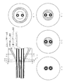
本発明のコントロールチューブは、2本以上の内芯チューブと、これらの内芯チューブの外側及び間を覆う被覆保護カバーから構成される。内芯チューブの本数は、2本以上であれば特に制限はないが、通常2〜10本、好ましくは2〜4本である。本発明のコントロールチューブの外径は、内芯チューブの本数、外径等により異なるが、通常5〜16mm×内芯チューブの本数である。内芯チューブの外径及び内径は、通常3.5〜13mm×2〜9.5mmである。本発明のコントロールチューブの断面の形状は、通常、1本の内芯チューブの外側を被覆保護カバーが覆ってなる円形断面が2つ以上メガネ形に一列に連なった形状である。内芯チューブ2本、内芯チューブの外径及び内径8mm×6mm、コントロールチューブの外径10mm×2本並列タイプのコントロールチューブの正面図及び断面図を図1に示す。 The control tube of the present invention is composed of two or more inner core tubes and a covering protective cover that covers the outside and between these inner core tubes. Although the number of inner core tubes is not particularly limited as long as it is 2 or more, it is usually 2 to 10, preferably 2 to 4. The outer diameter of the control tube of the present invention varies depending on the number of inner core tubes, outer diameter, and the like, but is usually 5 to 16 mm × the number of inner core tubes. The outer diameter and inner diameter of the inner tube are usually 3.5 to 13 mm × 2 to 9.5 mm. The cross-sectional shape of the control tube of the present invention is usually a shape in which two or more circular cross-sections in which a covering protective cover covers the outer side of one inner core tube are arranged in a row in the shape of glasses. FIG. 1 shows a front view and a cross-sectional view of a control tube having two inner core tubes, an outer diameter and an inner diameter of 8 mm × 6 mm of the inner core tube, and an outer diameter of 10 mm × 2 of the control tube in parallel.
本発明においては、焼却処理を可能とし、廃棄時の負担を軽減するため、前記内芯チューブは主に、炭化水素から構成されるエラストマーからなる。更に、耐低温衝撃性を向上させ、被覆保護カバーのカバー材料押出成形時の加熱を受けても溶け難い高融点(160℃以上)であることから、内芯と保護カバーが溶け合わず、被覆保護カバーの剥離時の容易性を維持させるために、前記エラストマーは、主にブロックポリプロピレン及び水素添加スチレン系エラストマーから構成される層を含む。前記の効果の点から、内芯チューブの少なくとも外層側(被覆保護カバーに接する側)が前記の「主にブロックポリプロピレン及び水素添加スチレン系エラストマーから構成される層」であることが好ましい。 In the present invention, in order to enable incineration and reduce the burden at the time of disposal, the inner core tube is mainly made of an elastomer composed of hydrocarbon. Furthermore, it has low-temperature impact resistance and has a high melting point (160 ° C or higher) that does not melt even when heated during the extrusion of the cover material of the cover protection cover. In order to maintain the ease of peeling off the protective cover, the elastomer includes a layer mainly composed of block polypropylene and a hydrogenated styrene elastomer. From the viewpoint of the above effects, it is preferable that at least the outer layer side (side contacting the covering protective cover) of the inner tube is the above-mentioned “layer mainly composed of block polypropylene and hydrogenated styrene elastomer”.
前記の「主にブロックポリプロピレン及び水素添加スチレン系エラストマーから構成される層」に用いられるブロックポリプロピレンは、プロピレンと他のα−オレフィンとのブロック共重合体である。前記共重合体における他のα−オレフィンとしては、炭素数2〜8のもの、例えばエチレン、ブテン−1、ペンテン−1、ヘキセン−1、ヘプテン−1、オクテン−1などが挙げられるが、これらに限定されない。好ましくはエチレンである。また、該共重合体中における、前記他のα−オレフィン単位の含量は、特に制限されないが、通常40重量%以下、好ましくは30重量%以下、更に好ましくは20重量%以下である。また、ブロックポリプロピレンは、エチレンプロピレンゴム等のゴムなどの重合体を混合物又は共重合成分として、通常30重量%以下含有してもよい。 The block polypropylene used for the “layer mainly composed of block polypropylene and hydrogenated styrene elastomer” is a block copolymer of propylene and another α-olefin. Other α-olefins in the copolymer include those having 2 to 8 carbon atoms, such as ethylene, butene-1, pentene-1, hexene-1, heptene-1, octene-1, and the like. It is not limited to. Ethylene is preferable. The content of the other α-olefin units in the copolymer is not particularly limited, but is usually 40% by weight or less, preferably 30% by weight or less, and more preferably 20% by weight or less. The block polypropylene may contain a polymer such as rubber such as ethylene propylene rubber as a mixture or copolymer component, usually 30% by weight or less.
前記の「主にブロックポリプロピレン及び水素添加スチレン系エラストマーから構成される層」に用いられる水素添加スチレン系エラストマーは、ポリスチレンブロックと、水素添加されたビニル−イソプレンブロックが結合したトリブロック共重合体や、同じく水素添加されたビニル−ブタジエンブロックが結合したトリブロック共重合体、及び水素添加されたスチレンブタジエンゴムが結合したトリブロック共重合体等で構成されている。また、前記水素添加されたビニル−イソプレンブロックとビニル−ブタジエンブロック両者が結合した共重合体であってもよく、内芯チューブの要求特性に合わせて選択することができる。尚、何れの共重合体も所謂可塑剤を使用せずに柔軟性が得られるため、環境負荷物質のないクリーンな製品の生産が可能となる。 The hydrogenated styrene elastomer used in the above-mentioned “layer mainly composed of block polypropylene and hydrogenated styrene elastomer” is a triblock copolymer in which a polystyrene block and a hydrogenated vinyl-isoprene block are bonded. And a triblock copolymer bonded with a hydrogenated vinyl-butadiene block, a triblock copolymer bonded with a hydrogenated styrene butadiene rubber, and the like. Further, it may be a copolymer in which both the hydrogenated vinyl-isoprene block and the vinyl-butadiene block are bonded, and can be selected according to the required characteristics of the inner tube. In addition, since any copolymer can provide flexibility without using a so-called plasticizer, it is possible to produce a clean product free from environmentally hazardous substances.
前記層に用いられるブロックポリプロピレンと水素添加スチレン系エラストマーとの配合割合は、重量比で、好ましくは85:15〜30:70、更に好ましくは80:20〜40:60である。 The blending ratio of the block polypropylene and the hydrogenated styrene elastomer used in the layer is preferably 85:15 to 30:70, more preferably 80:20 to 40:60, by weight.
本発明において、内芯チューブは、主にブロックポリプロピレン及び水素添加スチレン系エラストマーから構成される層が外層に配されるものであれば特に制限はなく、当該層の単層構造でも、また他の炭化水素から構成されるエラストマーからなる層が内層側に配される多層構造でもよい。 In the present invention, the inner tube is not particularly limited as long as a layer mainly composed of block polypropylene and a hydrogenated styrene-based elastomer is arranged in the outer layer. A multilayer structure in which an elastomer layer composed of hydrocarbons is arranged on the inner layer side may be used.
これらの他の炭化水素から構成されるエラストマーとしては、炭化水素から構成される熱可塑性エラストマーであれば特に制限はないが、例えば、ポリスチレン(硬質相)とポリブタジエン、ポリイソプレン、ビニル−ポリイソプレン、水素添加ポリブタジエン、水素添加ポリイソプレン又は水素添加ビニル−ポリイソプレン(軟質相)とから構成されるポリスチレン系エラストマー;ポリオレフィン樹脂(例えば、ポリエチレン、ポリプロピレン)(硬質相)とエチレン−α−オレフィン共重合体、エチレン−α−オレフィン−非共役ポリエン共重合体(例えば、EPDM)又はブチルゴム(軟質相)とから構成されるポリオレフィン系エラストマーが挙げられる。前記ポリスチレン系エラストマーには、必要に応じてポリプロピレン等のポリオレフィン樹脂を配合してもよい。 The elastomer composed of these other hydrocarbons is not particularly limited as long as it is a thermoplastic elastomer composed of hydrocarbons. For example, polystyrene (hard phase) and polybutadiene, polyisoprene, vinyl-polyisoprene, Polystyrene elastomer composed of hydrogenated polybutadiene, hydrogenated polyisoprene or hydrogenated vinyl-polyisoprene (soft phase); polyolefin resin (for example, polyethylene, polypropylene) (hard phase) and ethylene-α-olefin copolymer And a polyolefin-based elastomer composed of an ethylene-α-olefin-non-conjugated polyene copolymer (for example, EPDM) or butyl rubber (soft phase). You may mix | blend polyolefin resin, such as a polypropylene, with the said polystyrene-type elastomer as needed.
内芯チューブの材料には、必要に応じて、前記の成分以外に、光安定剤、酸化防止剤、熱安定剤や、耐候性を向上させるための紫外線吸収剤等を配合することができる。前記光安定剤としては、内芯チューブのベース樹脂との相溶性がよく、耐紫外線効果に優れ、ベース樹脂の特性も低下させない点で、ヒンダードアミン系光安定剤が好ましい。ヒンダードアミン系光安定剤としては、例えばジブチルアミン−1,3,5−トリアジン−N,N’−ビス(2,2,6,6−テトラメチル−4−ピペリジル−1,6−ヘキサメチレンジアミンとN−(2,2,6,6−テトラメチル−4−ピペリジル)ブチルアミンとの重縮合物、コハク酸ジメチルと4−ヒドロキシ−2,2,6,6−テトラメチル−1−ピペリジンエタノールとの重合物、ビス(2,2,6,6−テトラメチル−4−ピペリジル)セバケート等が挙げられる。これらの各種ヒンダードアミン系光安定剤は、それぞれ単独で用いてもよいし、2種以上のものを併用してもよい。ヒンダードアミン系光安定剤を配合する場合の配合割合は、ベース樹脂100重量部に対して、通常0.3〜1重量部であり、耐紫外線効果が優れ、ベース樹脂特性及び成形バランスに影響を及ぼさない点から、0.5〜0.8重量部が好ましい。内芯チューブの材料に光安定剤、好ましくはヒンダードアミン系光安定剤を配合することにより、継手挿入用に被覆保護カバーが剥離された内心チューブ部分の紫外線劣化を防止することができる。 If necessary, the material of the inner core tube may contain a light stabilizer, an antioxidant, a heat stabilizer, an ultraviolet absorber for improving weather resistance, and the like in addition to the above components. As the light stabilizer, a hindered amine light stabilizer is preferable in that it has good compatibility with the base resin of the inner tube, is excellent in ultraviolet resistance, and does not deteriorate the characteristics of the base resin. As the hindered amine light stabilizer, for example, dibutylamine-1,3,5-triazine-N, N′-bis (2,2,6,6-tetramethyl-4-piperidyl-1,6-hexamethylenediamine and Polycondensate with N- (2,2,6,6-tetramethyl-4-piperidyl) butylamine, dimethyl succinate and 4-hydroxy-2,2,6,6-tetramethyl-1-piperidineethanol Polymers, bis (2,2,6,6-tetramethyl-4-piperidyl) sebacate, etc. These various hindered amine light stabilizers may be used alone or in combination of two or more. When the hindered amine-based light stabilizer is blended, the blending ratio is usually 0.3 to 1 part by weight with respect to 100 parts by weight of the base resin, and the UV resistance effect is excellent. From the point of not affecting the base resin properties and the molding balance, 0.5 to 0.8 parts by weight is preferable.By blending a light stabilizer, preferably a hindered amine light stabilizer, into the material of the inner tube, It is possible to prevent UV degradation of the inner tube portion from which the covering protective cover is peeled for inserting the joint.
前記被覆保護カバーは水酸化マグネシウム及びシリコーン系難燃剤を含有するノンハロゲン・ノンリン難燃性樹脂組成物からなる。 The covering protective cover is made of a non-halogen / non-phosphorus flame retardant resin composition containing magnesium hydroxide and a silicone flame retardant.
前記ノンハロゲン・ノンリン難燃性樹脂組成物のベース樹脂としては、ノンハロゲン樹脂であれば特に制限はないが、例えば、エチレン−酢酸ビニル共重合体、エチレン−アクリル酸エチル共重合体等のノンハロゲンビニル樹脂;ノンハロゲンオレフィン系樹脂が挙げられ、可塑剤を使用せずに柔軟性が得られる点で、エチレン−酢酸ビニル共重合体、エチレン−アクリル酸エチル共重合体が好ましく、エチレン−酢酸ビニル共重合体を主体とするものが更に好ましい。本明細書において、「エチレン−酢酸ビニル共重合体を主体とする」とは、当該ベース樹脂を構成する成分中、エチレン−酢酸ビニル共重合体が最も多いことを意味し、当該ベース樹脂を構成する成分中、エチレン−酢酸ビニル共重合体が80重量%以上であることが好ましい。前記ノンハロゲン・ノンリン難燃性樹脂組成物におけるベース樹脂の配合割合は、通常20〜50重量%、好ましくは25〜50重量%、更に好ましくは30〜50重量%、最も好ましくは40〜45重量%である。 The base resin of the non-halogen / non-phosphorus flame retardant resin composition is not particularly limited as long as it is a non-halogen resin. For example, non-halogen vinyl resins such as ethylene-vinyl acetate copolymer and ethylene-ethyl acrylate copolymer An ethylene-vinyl acetate copolymer and an ethylene-ethyl acrylate copolymer are preferable, and an ethylene-vinyl acetate copolymer is preferable in that flexibility is obtained without using a plasticizer. The main component is more preferable. In this specification, “mainly composed of an ethylene-vinyl acetate copolymer” means that the ethylene-vinyl acetate copolymer is the largest among the components constituting the base resin, and the base resin is constituted. Among the components to be used, the ethylene-vinyl acetate copolymer is preferably 80% by weight or more. The blending ratio of the base resin in the non-halogen / non-phosphorus flame retardant resin composition is usually 20 to 50% by weight, preferably 25 to 50% by weight, more preferably 30 to 50% by weight, and most preferably 40 to 45% by weight. It is.
また、内芯チューブ及び被覆保護カバーのベース樹脂をいずれもビニル樹脂とすることにより、チューブの生産から使用、及び使用済み後の廃棄の全てのプロセスにおいて、両者とも同様に取り扱うことができ、しかも、廃棄時は焼却処理を行っても、完全燃焼させれば発生ガスは水蒸気及び炭酸ガスのみで、有害ガスの発生は皆無で、人や環境に対し負荷を与えることはない。当然ながら、燃料として使用することも可能であり、焼却時もエネルギーとしての貢献を果たすことが可能である。 Also, by using vinyl resin as the base resin for the inner tube and the covering protective cover, both can be handled in the same way in all processes from tube production to use and disposal after use. Even if an incineration process is performed at the time of disposal, if it is completely burned, the generated gas is only water vapor and carbon dioxide gas, no harmful gas is generated, and there is no burden on people and the environment. Of course, it can also be used as fuel, and can contribute to energy during incineration.
本発明においては、ハロゲン系化合物等の環境負荷物質を使用せずに、難燃性とするために、被覆保護カバー材料であるノンハロゲン・ノンリン難燃性樹脂組成物中に水酸化マグネシウムを配合させる。水酸化マグネシウムは、難燃性が良好であり、ベース樹脂であるノンハロゲン樹脂との相溶性及び分散性に優れ機械特性を低下させない。水酸化マグネシウムの配合割合は、ノンハロゲン・ノンリン難燃性樹脂組成物中、通常40〜60重量%、好ましくは48〜53重量%であり、ベース樹脂100重量部に対して、通常100〜150重量部、好ましくは110〜130重量部である。 In the present invention, magnesium hydroxide is added to the non-halogen / non-phosphorus flame retardant resin composition, which is a coating protective cover material, in order to make it flame retardant without using environmentally hazardous substances such as halogen compounds. . Magnesium hydroxide has good flame retardancy and is excellent in compatibility and dispersibility with a non-halogen resin as a base resin, and does not deteriorate mechanical properties. The blending ratio of magnesium hydroxide is usually 40 to 60% by weight, preferably 48 to 53% by weight in the halogen-free and phosphorus-free flame retardant resin composition, and is usually 100 to 150% by weight with respect to 100 parts by weight of the base resin. Parts, preferably 110 to 130 parts by weight.
また、本発明においては、被覆保護カバーの引き裂き易さ及び剥離性の点で、被覆保護カバー材料であるノンハロゲン・ノンリン難燃性樹脂組成物中に、シリコーン系難燃剤を配合することが必要であり、更に無機充填剤を配合することが好ましい。 In the present invention, it is necessary to add a silicone flame retardant to the non-halogen / non-phosphorus flame retardant resin composition, which is a coating protective cover material, in terms of ease of tearing and peelability of the protective cover. In addition, it is preferable to blend an inorganic filler.
前記シリコーン系難燃剤としては、ケイ素原子を含有する有機化合物であれば特に制限はなく、例えばシリコーンオイル、シリコーンゴム、シリコーン樹脂が挙げられる。前記シリコーンオイルとしては、例えばジメチルシリコーンオイル、メチルフェニルシリコーンオイル、メチルハイドロジエンシリコーンオイル、ポリエーテル変性シリコーンオイルが挙げられる。前記シリコーンゴムとしては、例えばメチルシリコーンゴム、メチルフェニルシリコーンゴムが挙げられる。前記シリコーン樹脂としては、例えばメチルシリコーン、メチルフェニルシリコーン、フェニルシリコーンが挙げられる。また前記ケイ素原子を含有する有機化合物は、−OH、−NH2、−NCO、−COOH、−CHO、−SH、メチロール基、アクリレート基、メタクリレート基、シリル基、グリシジル基又はエポキシ基等の官能基を有していてもよい。 The silicone flame retardant is not particularly limited as long as it is an organic compound containing a silicon atom, and examples thereof include silicone oil, silicone rubber, and silicone resin. Examples of the silicone oil include dimethyl silicone oil, methylphenyl silicone oil, methyl hydrogen silicone oil, and polyether-modified silicone oil. Examples of the silicone rubber include methyl silicone rubber and methylphenyl silicone rubber. Examples of the silicone resin include methyl silicone, methyl phenyl silicone, and phenyl silicone. The organic compound containing a silicon atom is a functional group such as —OH, —NH 2 , —NCO, —COOH, —CHO, —SH, methylol group, acrylate group, methacrylate group, silyl group, glycidyl group or epoxy group. It may have a group.
前記シリコーン系難燃剤の配合割合は、ノンハロゲン・ノンリン難燃性樹脂組成物中、通常1.0〜2.0重量%、好ましくは1.2〜1.3重量%であり、ベース樹脂100重量部に対して、通常2.3〜4.7重量部、好ましくは2.8〜3.0重量部である。 The blending ratio of the silicone flame retardant is usually 1.0 to 2.0% by weight, preferably 1.2 to 1.3% by weight, and 100% by weight of the base resin in the non-halogen / non-phosphorus flame retardant resin composition. The amount is usually 2.3 to 4.7 parts by weight, preferably 2.8 to 3.0 parts by weight with respect to parts.
前記無機充填剤としては、難燃性樹脂組成物に配合することができる、水酸化マグネシウム以外の無機充填剤であれば特に制限はなく、例えばスズ酸亜鉛に代表される無機酸化物類、ケイ酸塩類、炭酸塩類、モリブデン類等が挙げられ、好ましくはスズ酸亜鉛、炭酸マグネシウム等の剥離性改善効果等の改質効果を有する無機充填剤が挙げられる。 The inorganic filler is not particularly limited as long as it is an inorganic filler other than magnesium hydroxide that can be blended in the flame retardant resin composition. For example, inorganic oxides represented by zinc stannate, silica Examples include acid salts, carbonates, molybdenum, and the like, and preferred examples include inorganic fillers having a modifying effect such as a peelability improving effect such as zinc stannate and magnesium carbonate.
前記無機充填剤の配合割合は、ノンハロゲン・ノンリン難燃性樹脂組成物中、通常2.0〜10.0重量%、好ましくは3.0〜5.0重量%であり、ベース樹脂100重量部に対して、通常4.6〜23.2重量部、好ましくは7.1〜11.6重量部である。 The blending ratio of the inorganic filler is usually 2.0 to 10.0% by weight, preferably 3.0 to 5.0% by weight, and 100 parts by weight of the base resin in the non-halogen / non-phosphorus flame retardant resin composition. Is usually 4.6 to 23.2 parts by weight, preferably 7.1 to 11.6 parts by weight.
前記ノンハロゲン・ノンリン難燃性樹脂組成物には、必要に応じて、前記の成分以外に、加工性改良剤、酸化防止剤、改質剤、架橋剤、顔料、紫外線吸収剤、熱安定剤等を配合することができる。 In the non-halogen / non-phosphorus flame retardant resin composition, a processability improver, an antioxidant, a modifier, a crosslinking agent, a pigment, an ultraviolet absorber, a heat stabilizer, etc., in addition to the above components, as necessary Can be blended.
また、内芯チューブ及び被覆保護カバーの材料には、環境ホルモン等の環境影響性の点で、DOP等の可塑剤は配合しないことが好ましい。 Moreover, it is preferable not to mix | blend plasticizers, such as DOP, with the material of an inner core tube and a covering protective cover from the point of environmental influences, such as an environmental hormone.
本発明のコントロールチューブは、例えば、次のようにして製造することができる。
先ず、内芯チューブ用のブロックポリプロピレンと水素添加スチレン系エラストマーからなるチューブを、予め、押出成形機を用いて生産する。
The control tube of the present invention can be manufactured, for example, as follows.
First, a tube made of block polypropylene for an inner core tube and a hydrogenated styrene elastomer is produced in advance using an extruder.
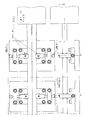
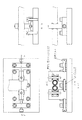
次いで、大気中で十分に冷却安定するまで保管された前記内芯チューブを、目的とするコントロールチューブの形状に応じて、例えば、2連タイプ(内芯チューブ2本使用)では図2〜4に示すチューブ製造用治具、4連タイプ(内芯チューブ4本使用)では図5〜7に示すチューブ製造用治具の金型内に導き入れ、押出機により、ノンハロゲン・ノンリン難燃樹脂組成物からなる樹脂原料を用いて被覆保護カバー掛け成形を行う。 Next, according to the shape of the target control tube, the inner tube stored until the air is sufficiently cooled and stabilized in the atmosphere, for example, in a double type (using two inner core tubes) is shown in FIGS. In the tube manufacturing jig shown, the four-line type (using four inner core tubes) is introduced into the mold of the tube manufacturing jig shown in FIGS. Using a resin raw material consisting of
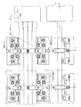
前記2段階の生産方式による2連タイプ(内芯チューブ2本)の製造ラインの一例を図8に示す。
図8の内芯チューブ用ドラムに予め巻かれていた2本の内芯チューブは、引取り機により引き出され、押出機のクロスヘッド金型内に導かれ、図2の2連タイプ用マンドレル金型内を通過する。この時、同時に押出機により押し出された被覆保護カバー材料は、2連タイプ用ダイ金型を通り、2本の内芯チューブの外周に均一に被せられる。被覆された保護カバー2連はダイを通過した時点ではまだ接着(溶着)されてはいないが、押し出された直後で高温状態にあるため、図3及び図4の押付け用ローラーガイドにより押付けられることにより、ローラーガイドの反対部分が互いに接着(溶着)し合い、図1の形状が得られる。また、図3及び図4の押付け用ローラーガイドは冷却水槽内にも設けられているため、安定した接着(溶着)強度が得られる。
An example of a production line of the double type (two inner core tubes) by the two-stage production method is shown in FIG.
The two inner tube tubes previously wound around the inner tube drum shown in FIG. 8 are drawn out by a take-out machine and guided into the crosshead mold of the extruder, and the mandrel die for the double type shown in FIG. Pass through the mold. At this time, the covering protective cover material extruded by the extruder at the same time passes uniformly through the outer periphery of the two inner core tubes through the double die mold. The two coated protective covers are not yet bonded (welded) at the time of passing through the die, but they are in a high temperature state immediately after being pushed out, so that they are pressed by the pressing roller guide of FIGS. 3 and 4. As a result, the opposite portions of the roller guide are bonded (welded) to each other, and the shape shown in FIG. 1 is obtained. In addition, since the pressing roller guide of FIGS. 3 and 4 is also provided in the cooling water tank, stable adhesion (welding) strength can be obtained.
但し、本工程を用いる場合、被覆保護カバー材料が高温のままの状態で押付け用ローラーガイドにより押付けられるため、被覆保護カバーの熱が内芯チューブに伝わり、ローラーガイド側の被覆保護カバーと内芯チューブ自体が接着(溶着)してしまい、被覆保護カバーの剥離性に問題が生じる可能性がある。従って、被覆保護カバーと内芯チューブを接着(溶着)させない対策として、前記のように、高融点(160℃以上)の「主にブロックポリプロピレン及び水素添加スチレン系エラストマーから構成される層」が内芯チューブの少なくとも外層側に配される必要性がある。 However, when this process is used, the cover protection cover material is pressed by the pressing roller guide while the temperature is still high, so the heat of the cover protection cover is transferred to the inner tube, and the cover protection cover and inner core on the roller guide side are transferred. The tube itself may be bonded (welded), which may cause a problem in the peelability of the covering protective cover. Therefore, as a measure to prevent the covering protective cover and the inner core tube from being bonded (welded), as described above, a “layer mainly composed of block polypropylene and hydrogenated styrene elastomer” having a high melting point (160 ° C. or higher) is used. There is a need to be disposed at least on the outer layer side of the core tube.
尚、図8の押出成形機及びクロスヘッド金型に向き合う形でもう1台の押出成形機及びクロスヘッド金型を設置することにより、2連タイプの被覆保護カバーに2色の着色が可能となり、内部流体仕様(冷却水のIN・OUTやバルブやシリンダーの方向性等)の識別等が外部から可能となる。 By installing another extruder and crosshead mold so as to face the extrusion machine and crosshead mold shown in FIG. 8, two colors can be colored on the double-type covering protective cover. In addition, identification of internal fluid specifications (IN / OUT of cooling water, directionality of valves and cylinders, etc.) is possible from the outside.
また、図5、図6及び図7は、2連タイプのダイ金型や、マンドレル金型、及び押付け用ローラーガイドを4連タイプに展開したものであり、基本的な成形方法は2連タイプの図8に準ずるが、4連であるため、製品並列時の上下への凹凸を防止するため、図7に示すように、整列用ローラーガイドが設けられている。 FIGS. 5, 6 and 7 show a double-type die mold, a mandrel mold, and a pressing roller guide developed into a quadruple type. The basic molding method is a double-type. However, as shown in FIG. 7, an alignment roller guide is provided in order to prevent unevenness in the vertical direction when the products are arranged in parallel.
前記2段階の生産方式によらずに、例えば、2層同時押出成形方式を用いると、内芯チューブ用樹脂と、被覆保護カバー樹脂が、互いに溶融し合い、本発明の目的である、「被覆保護カバー」の剥離自体が全く不可能となる。 If, for example, a two-layer coextrusion molding method is used instead of the two-stage production method, the resin for the inner core tube and the covering protective cover resin melt together, which is the object of the present invention. It is impossible to remove the protective cover.
また、前記2段階の生産方式を用いても、2連タイプや4連タイプのように同時に被覆保護カバー成形をせず、1本毎にコントロールチューブを生産し、2本のコントロールチューブを後工程で加熱して溶着加工する方法や、接着剤を用いて接着加工する方法もあるが、1本毎の成形のため、成形時間も倍となり、後工程の溶着や接着加工工程も増加するため、コストアップとなり経済的にデメリットとなる。しかも、後工程による加熱による溶着加工や、接着剤を用いる接着加工は、加熱温度調節や接着剤の塗布量等不安定要素が増加し、接着(溶着)強度の安定性等において、品質的問題が発生し易くなる。 Even if the above two-stage production method is used, the control tube is produced for each one without forming the protective cover at the same time as in the case of the double type or the quadruple type. There is also a method of welding processing by heating with, and a method of bonding processing using an adhesive, but because of the molding of each one, the molding time is doubled, and the welding and bonding processing steps in the subsequent process increase, This increases costs and is economically disadvantageous. In addition, the welding process by heating in the subsequent process and the bonding process using an adhesive increase the unstable factors such as the adjustment of the heating temperature and the amount of the adhesive applied, and there is a quality problem in the stability of the bonding (welding) strength. Is likely to occur.
前記2段階の生産方式を用いても、内芯チューブ及び被覆保護カバーのベース樹脂をともにビニル樹脂にすると、相溶性があるため、内芯チューブと被覆保護カバーが溶け合い接着状態となり、剥離しにくくなる。本発明では、少なくとも内芯チューブの外層側(被覆保護カバーに接する側)を前記の「主にブロックポリプロピレン及び水素添加スチレン系エラストマーから構成される層」にすることにより、高融点(160℃以上)のために、被覆保護カバーのカバー掛け成形時、特に押付け用ローラーガイドにより押付けられても、内芯チューブと被覆保護カバーの溶着は発生せず、被覆保護カバーの剥離は容易となり、更にブロックプロピレンの特徴である耐低温衝撃性も向上する。前記ブロックポリプロピレンの替わりにランダムポリプロピレンを用いると、融点が低いために、カバー掛け成形時、特に押付け用ローラーガイドに押付けられる際に、被覆保護カバーと内芯チューブの溶着部分が発生し、被覆保護カバーの剥離が困難になり、耐低温衝撃性も低下する。また、前記ブロックポリプロピレンの替わりにホモポリプロピレンを用いると、耐衝撃性が著しく低下する。ブロックポリプロピレンを用いると低下する特性として透明性(内部流体の視認性)の低下があげられるが、本コントロールチューブのように被覆保護カバー付の製品の際は、透明である必要は全くない。 Even if the above two-stage production method is used, if the base resin of the inner core tube and the covering protective cover are both made of vinyl resin, they are compatible. Become. In the present invention, at least the outer layer side of the inner core tube (the side in contact with the covering protective cover) is the above-mentioned “layer mainly composed of block polypropylene and hydrogenated styrene elastomer”, thereby achieving a high melting point (160 ° C. or higher). For this reason, when the cover protection cover is molded, especially when it is pressed by the pressing roller guide, the inner tube and the cover protection cover do not weld, making it easy to peel off the cover protection cover and block. The low temperature impact resistance characteristic of propylene is also improved. When random polypropylene is used in place of the block polypropylene, the melting point is low, so when the cover is molded, especially when it is pressed against the roller guide for pressing, a welded part of the cover protection cover and the inner core tube is generated, covering protection The cover becomes difficult to peel off, and the low-temperature impact resistance also decreases. Further, when homopolypropylene is used instead of the block polypropylene, impact resistance is remarkably lowered. A characteristic that decreases when block polypropylene is used is a decrease in transparency (visibility of internal fluid). However, in the case of a product with a protective covering cover such as the present control tube, it does not have to be transparent at all.
本発明のコントロールチューブは、各内芯チューブを被覆保護カバーで被覆した状態で分割することができるので、各内芯チューブに継手を装着できる。使用に際しては、端部を分割し、継手挿入部のサイズに合わせて被覆保護カバーをカッター等で切り裂いて継手に挿入すれば、内芯チューブが露出する部分が生じるのを防止することができる(図9参照)。 Since the control tube of the present invention can be divided in a state where each inner core tube is covered with a covering protective cover, a joint can be attached to each inner core tube. In use, if the end portion is divided, and the covering protective cover is cut with a cutter or the like according to the size of the joint insertion portion and inserted into the joint, it is possible to prevent the exposed portion of the inner core tube from being formed ( (See FIG. 9).
以下、実施例をあげて本発明を更に具体的に説明するが、本発明の範囲はこれらに限定されるものではない。
(実施例1)
(1)内芯チューブの製造
次のようにして、外径8mm、内径6mmの内芯チューブを、黒色顔料を配合した黒色内芯チューブと黒色顔料を配合しない半透明内芯チューブのそれぞれ1本製造した。
通常のストレート型押出成形機により、主成分がブロックポリプロピレンと水素添加スチレン系エラストマーからなる原料樹脂(ブロックポリプロピレンと水素添加スチレン系エラストマーとの重量比:80:20;ヒンダードアミン系光安定剤0.6重量%添加)を用いて、予め、内芯用チューブの製造を行った。
Hereinafter, the present invention will be described more specifically with reference to examples. However, the scope of the present invention is not limited to these examples.
Example 1
(1) Manufacture of inner core tube In the following manner, an inner core tube having an outer diameter of 8 mm and an inner diameter of 6 mm, one each of a black inner tube containing a black pigment and a translucent inner tube not containing a black pigment. Manufactured.
Raw material resin consisting mainly of block polypropylene and hydrogenated styrene elastomer (weight ratio of block polypropylene to hydrogenated styrene elastomer: 80:20; hindered amine light stabilizer 0.6) The tube for the inner core was manufactured in advance using (weight% addition).
(2)被覆保護カバーの形成
図8に示すコントロールチューブ製造ラインに設けた図2の2連タイプ用マンドレル金型内に、前記(1)で製造した黒色及び半透明の内芯チューブ各1本を導き入れ、エチレン−酢酸ビニル共重合体43重量%、水酸化マグネシウム51重量%、シリコーン系難燃剤(難燃助剤及び剥離性改善剤)1.3重量%、無機充填剤(剥離性改善等改質剤)4.3重量%、その他(加工性改良剤、酸化防止剤、改質剤、架橋剤、顔料)からなる樹脂組成物を、押出成形機により押し出し、2連タイプ用ダイ金型を使用して、2本の内芯チューブの外側及び間に被覆保護カバーを形成させた後、金型出口及び冷却水槽内の押付け用ローラーガイドにより相互を押付け溶着させて図1に示すコントロールチューブを製造した。
(2) Formation of covering protective cover One black and semi-transparent inner core tube manufactured in (1) above in the double-type mandrel mold of FIG. 2 provided in the control tube manufacturing line shown in FIG. , 43% by weight of ethylene-vinyl acetate copolymer, 51% by weight of magnesium hydroxide, 1.3% by weight of silicone-based flame retardant (flame retardant aid and peelability improving agent), inorganic filler (improvement of peelability) Equal modifier) 4.3% by weight and other (processability improver, antioxidant, modifier, cross-linking agent, pigment) are extruded by an extruder and die for double type The cover shown in FIG. 1 is formed by forming a covering protective cover between and outside the two inner core tubes using a mold, and then pressing and welding each other with a pressing roller guide in the mold outlet and the cooling water tank. Manufactured tube .
Claims (7)
Priority Applications (1)
| Application Number | Priority Date | Filing Date | Title |
|---|---|---|---|
| JP2008215826A JP5225788B2 (en) | 2008-08-25 | 2008-08-25 | Parallel control tube |
Applications Claiming Priority (1)
| Application Number | Priority Date | Filing Date | Title |
|---|---|---|---|
| JP2008215826A JP5225788B2 (en) | 2008-08-25 | 2008-08-25 | Parallel control tube |
Publications (2)
| Publication Number | Publication Date |
|---|---|
| JP2010046999A JP2010046999A (en) | 2010-03-04 |
| JP5225788B2 true JP5225788B2 (en) | 2013-07-03 |
Family
ID=42064494
Family Applications (1)
| Application Number | Title | Priority Date | Filing Date |
|---|---|---|---|
| JP2008215826A Expired - Fee Related JP5225788B2 (en) | 2008-08-25 | 2008-08-25 | Parallel control tube |
Country Status (1)
| Country | Link |
|---|---|
| JP (1) | JP5225788B2 (en) |
Family Cites Families (8)
| Publication number | Priority date | Publication date | Assignee | Title |
|---|---|---|---|---|
| JPS604054A (en) * | 1983-06-23 | 1985-01-10 | 新日本製鐵株式会社 | Polypropylene coated steel pipe |
| JP4364315B2 (en) * | 1996-08-22 | 2009-11-18 | Jfeスチール株式会社 | Polypropylene-coated steel pipe excellent in heat-resistant oxidative degradation and weather resistance and method for producing the same |
| JP2001219500A (en) * | 2000-02-07 | 2001-08-14 | Hitachi Cable Ltd | Resin-coated flexible steel pipe and its resin composition |
| JP2001271968A (en) * | 2000-03-24 | 2001-10-05 | Tokai Rubber Ind Ltd | Multiple resin hose with binding protector and method of manufacturing the same |
| JP3944634B2 (en) * | 2002-02-07 | 2007-07-11 | 住友電装株式会社 | Flame retardant resin composition, non-halogen insulated wire and wire harness using the same |
| JP2004044733A (en) * | 2002-07-12 | 2004-02-12 | Furukawa Electric Co Ltd:The | Composite pipe and method of manufacturing the same |
| JP2006083323A (en) * | 2004-09-17 | 2006-03-30 | Riken Technos Corp | Thermoplastic elastomer composition for injection molding |
| JP4852259B2 (en) * | 2005-05-13 | 2012-01-11 | 株式会社アオイ | Control tube |
-
2008
- 2008-08-25 JP JP2008215826A patent/JP5225788B2/en not_active Expired - Fee Related
Also Published As
| Publication number | Publication date |
|---|---|
| JP2010046999A (en) | 2010-03-04 |
Similar Documents
| Publication | Publication Date | Title |
|---|---|---|
| US7255134B2 (en) | Carbon black-containing crosslinked polyethylene pipe having resistance to chlorine and hypochlorous acid | |
| JP4894262B2 (en) | Non-halogen flame retardant cable | |
| JP2009255578A (en) | Crosslinked polyethylene pipe having high density polyethylene lining layer | |
| TW200832450A (en) | Flexible flat cable | |
| JP4890385B2 (en) | Control tube | |
| JP5225788B2 (en) | Parallel control tube | |
| JP5367248B2 (en) | Multi-layer insulated wire | |
| JP4852259B2 (en) | Control tube | |
| CN103259241B (en) | A kind of Memorability exempts from the processing technology of the seal closure dismantling power pipeline junction and special extruder head | |
| KR102280366B1 (en) | laminate | |
| JP2001219500A (en) | Resin-coated flexible steel pipe and its resin composition | |
| JP4525387B2 (en) | Optical fiber cord | |
| EP0646623B1 (en) | Polymeric composition based on very low density polyethylenes and their use for lining tunnels | |
| JP4277680B2 (en) | Flame retardant resin composition and optical fiber cord using the same | |
| CN105602212A (en) | Extruded plastic part based on an adhesive fire-resistant coating on a plastic substrate and method for its production | |
| JP2001139829A (en) | Thermoplastic elastomer composition and hose using the same | |
| JP2001110251A (en) | Insulated wire/cable | |
| KR101863319B1 (en) | Multi-layer Polyethylene film for replaying soft-melting PVC film in use of the protecting tape | |
| KR20110003882A (en) | Automobile light protection film and manufacturing method thereof | |
| BR112019020251B1 (en) | LAMINATE, HOSE AND METHOD FOR PRODUCING A LAMINATE | |
| JPH079639A (en) | Water stop sheet for civil engineering | |
| JP2007277942A (en) | Connection device in enclosure |
Legal Events
| Date | Code | Title | Description |
|---|---|---|---|
| A621 | Written request for application examination |
Free format text: JAPANESE INTERMEDIATE CODE: A621 Effective date: 20110411 |
|
| A977 | Report on retrieval |
Free format text: JAPANESE INTERMEDIATE CODE: A971007 Effective date: 20120601 |
|
| A131 | Notification of reasons for refusal |
Free format text: JAPANESE INTERMEDIATE CODE: A131 Effective date: 20120612 |
|
| A521 | Request for written amendment filed |
Free format text: JAPANESE INTERMEDIATE CODE: A523 Effective date: 20120719 |
|
| TRDD | Decision of grant or rejection written | ||
| A01 | Written decision to grant a patent or to grant a registration (utility model) |
Free format text: JAPANESE INTERMEDIATE CODE: A01 Effective date: 20130305 |
|
| A61 | First payment of annual fees (during grant procedure) |
Free format text: JAPANESE INTERMEDIATE CODE: A61 Effective date: 20130313 |
|
| R150 | Certificate of patent or registration of utility model |
Ref document number: 5225788 Country of ref document: JP Free format text: JAPANESE INTERMEDIATE CODE: R150 Free format text: JAPANESE INTERMEDIATE CODE: R150 |
|
| FPAY | Renewal fee payment (event date is renewal date of database) |
Free format text: PAYMENT UNTIL: 20190322 Year of fee payment: 6 |
|
| R250 | Receipt of annual fees |
Free format text: JAPANESE INTERMEDIATE CODE: R250 |
|
| R250 | Receipt of annual fees |
Free format text: JAPANESE INTERMEDIATE CODE: R250 |
|
| R250 | Receipt of annual fees |
Free format text: JAPANESE INTERMEDIATE CODE: R250 |
|
| R250 | Receipt of annual fees |
Free format text: JAPANESE INTERMEDIATE CODE: R250 |
|
| R250 | Receipt of annual fees |
Free format text: JAPANESE INTERMEDIATE CODE: R250 |
|
| LAPS | Cancellation because of no payment of annual fees |