JP5218924B2 - Plug-in fitting - Google Patents
Plug-in fitting Download PDFInfo
- Publication number
- JP5218924B2 JP5218924B2 JP2011142772A JP2011142772A JP5218924B2 JP 5218924 B2 JP5218924 B2 JP 5218924B2 JP 2011142772 A JP2011142772 A JP 2011142772A JP 2011142772 A JP2011142772 A JP 2011142772A JP 5218924 B2 JP5218924 B2 JP 5218924B2
- Authority
- JP
- Japan
- Prior art keywords
- joint
- protective cap
- cylindrical portion
- ring
- peripheral surface
- Prior art date
- Legal status (The legal status is an assumption and is not a legal conclusion. Google has not performed a legal analysis and makes no representation as to the accuracy of the status listed.)
- Active
Links
Images
Landscapes
- Joints With Sleeves (AREA)
Description
本発明は、給水用、給湯用などの樹脂管の内周面を抜止部材により係止する形式の差込み型継手、また樹脂管の挿入方向に移動する加圧部材で樹脂管を保護する形式の差込み型継手、さらにこのとき樹脂管の挿入確認の出来る差込型継手に関する。 The present invention is a plug-in type joint in which the inner peripheral surface of a resin pipe for water supply or hot water supply is locked by a retaining member, or a type in which the resin pipe is protected by a pressure member that moves in the resin tube insertion direction. The present invention relates to a plug-in type joint, and further to a plug-in type joint capable of confirming the insertion of a resin pipe.
従来、ガス管、水道管等の流体輸送管として使用されている、ポリエチレン(PE)、ポリブテン(PB)、ポリプロピレン(PP)等のポリオレフィン系樹脂で形成された樹脂管は種々の方法で接合されるが、接合手段としては、一般的には、継手本体にナットを螺合し、継手本体とナット内に装着したパッキンや食い込みリングを圧縮することで接続するメカニカル方式の管継手が使用されている。このメカニカル方式の管継手によれば、管端部外面に食い込みリングを組付け次いでレンチにより継手本体にナットを締め付けることにより接続が行われる。しかし、上記のメカニカル式管継手は、管の挿入が確実に行われたか否かの管挿入確認が施工完了後に出来ないという欠点があり、さらにナットの締め付け程度についても確認が困難であり、管接続部の性能にバラツキが生じ易かった。従って、管の挿入不足や、ナットの締め付け不足あるいは食い込みリングの装着ミスが発生しても、施工直後に行う短期の漏れテストだけでは、これらの不具合を検出することができず、長期間の使用時に接続管の抜けや、流体の漏れを発生することがある。 Conventionally, resin pipes made of polyolefin resins such as polyethylene (PE), polybutene (PB), and polypropylene (PP), which are used as fluid transport pipes such as gas pipes and water pipes, are joined by various methods. However, as a joining means, generally, a mechanical type pipe joint is used in which a nut is screwed into the joint body, and the joint body and the packing or biting ring mounted in the nut are compressed and connected. Yes. According to this mechanical-type pipe joint, the biting ring is assembled on the outer surface of the pipe end, and then the nut is fastened to the joint main body with a wrench to make the connection. However, the mechanical pipe joints described above have the drawback that the pipe insertion confirmation as to whether or not the pipe has been securely inserted cannot be performed after the completion of the construction, and it is difficult to confirm the tightening degree of the nut. It was easy for variations in the performance of the connecting part to occur. Therefore, even if there is insufficient pipe insertion, nut tightening or a biting ring installation error, these shortcomings cannot be detected by a short-term leak test performed immediately after construction, and long-term use is not possible. Occasionally, disconnection of the connecting pipe or fluid leakage may occur.
これらの問題点を解消する従来例として、樹脂製パイプの端部に挿入される挿入筒部を有し、その外周にシール部材が装着されている継手本体と、挿入筒部に外嵌されたパイプの端部を弾発的な締め付け力で締め付けるためのスリット付きの締付環体と、締付環体の弾発力に抗して締付環体を拡径するようにスリットの端部に離脱可能に挟持されて、パイプの先端部に当接して離脱する拡径片とを備えた差込み型継手が提案されている(特許文献1参照)。この差込み型継手は、その主要部が継手本体と締付環体と拡径片で構成されているので、従来の多数の部品を組み合わせた継手構造に比べて製造コストが低減され、かつ、小型の工具で接続作業が簡単に行え、接続強度のバラつきがなく、施工後の接続確認も容易であり、管の接続作業時の部品組付け作業や拡管作業などの面倒な作業が解消されるという多数の利点を有する。 As a conventional example for solving these problems, a joint body having an insertion cylinder portion inserted into an end portion of a resin pipe and having a seal member mounted on the outer periphery thereof, and the fitting body is externally fitted to the insertion cylinder portion. A tightening ring with a slit to tighten the end of the pipe with a resilient tightening force, and an end of the slit to expand the diameter of the tightening ring against the elastic force of the tightening ring There has been proposed a plug-in joint provided with a diameter-expanding piece that is detachably sandwiched between and abutted against the tip of a pipe (see Patent Document 1). The main part of this plug-in type joint is composed of a joint body, a tightening ring, and a diameter-expanding piece. Therefore, the manufacturing cost is reduced compared to a conventional joint structure in which a large number of parts are combined. With this tool, connection work can be performed easily, connection strength does not vary, connection confirmation after construction is easy, and troublesome work such as parts assembly work and pipe expansion work during pipe connection work is eliminated. Has a number of advantages.
また、上記締付環体をカバーで覆い、その外周面に形成された雄ネジに袋ナットを螺合することにより、着脱自在に締め付け固定することが提案されている(特許文献2参照)。この差込み型継手によれば、締付環体をそのスリットに拡径片を挟持した状態で継手本体に装着し、継手本体にパイプを挿入することにより、圧入状態の拡径片に対して回転モーメントが作用して、拡径片がスリットから離脱し、挿入筒部に外嵌されたパイプの端部が締付けられるように構成される。 In addition, it has been proposed to detachably fasten the cover by covering the tightening ring with a cover and screwing a cap nut onto a male screw formed on the outer peripheral surface thereof (see Patent Document 2). According to this plug-in type joint, the clamping ring is attached to the joint body with the diameter-enlarged piece held between the slits, and the pipe is inserted into the joint body, so that it can rotate with respect to the press-fit state diameter-enlarged piece. When the moment acts, the diameter-expanding piece is detached from the slit, and the end portion of the pipe externally fitted to the insertion cylinder portion is tightened.
また、上記問題点を解消する他の従来例として、外周に形成されたシールリング溝に弾性シールリングが嵌め込まれた内筒体を有する継手本体と、継手本体に一端部がねじ込まれた外筒体と、外筒体の外周に螺合されたナットと、外筒体の端面に当接する鍔部と外筒体の内周面に挿入されかつ内周に食込み歯を有するロックリングが先端に形成された中空軸とからなるコレットと、内周面の前端部から後方に向かって漸次窄まる前方拡がり状のテーパが形成されかつ後端部の外周に中空軸内の段差部に係合する複数の弾性係合爪が径方向外方へ切り起こす形で列設されたテーパ付リングを備えた差込み型継手が提案されている(特許文献3参照)。この差込み型継手は、樹脂管の一端部をコレットの中空軸に挿入し、管の切断端面でテーパ付リングが差込み間隙の内奥方向へ押し込まれ、テーパが弾性シールリングを圧縮しながらそこを通過するので、樹脂管の切断端面が面取りされていなくてもスムーズに挿入される。また、テーパ付リングのテーパはこのリングの内周面の前端部から後端部までの全長にわたって形成できるので、非常に撓み易くなり、ある程度斜めに切断された管であっても挿入することができる。 As another conventional example for solving the above problems, a joint body having an inner cylinder body in which an elastic seal ring is fitted in a seal ring groove formed on the outer periphery, and an outer cylinder having one end screwed into the joint body Body, a nut screwed to the outer periphery of the outer cylinder, a collar contacting the end surface of the outer cylinder, and a lock ring inserted into the inner peripheral surface of the outer cylinder and having a biting tooth on the inner periphery A collet composed of the formed hollow shaft and a forward-expanding taper that gradually narrows backward from the front end portion of the inner peripheral surface and is engaged with a stepped portion in the hollow shaft on the outer periphery of the rear end portion. There has been proposed a plug-in type joint including a tapered ring in which a plurality of elastic engagement claws are arranged in a form of cutting out radially outward (see Patent Document 3). In this plug-in type joint, one end of a resin tube is inserted into the hollow shaft of the collet, the tapered ring is pushed into the insertion gap in the cut end surface of the tube, and the taper compresses the elastic seal ring while compressing it. Since it passes, even if the cut end surface of the resin tube is not chamfered, it is smoothly inserted. In addition, the taper of the tapered ring can be formed over the entire length from the front end portion to the rear end portion of the inner peripheral surface of the ring, so that it is very easy to bend, and even a tube cut to a certain degree can be inserted. it can.
また、上記問題点を解消する更に他の従来例として、継手本体の外周に形成した雄ねじ部の内側に接続管を外嵌する円筒状の案内部を設け、この案内部に外周面に溝孔を形成し、この溝孔に樹脂管の内周面に密着するシール部材を装着し、さらに前記雄ねじ部に螺着する袋ナットと案内部の間にリングを介在させる差込み型継手が提案されている。また、ストッパーに当たるまで挿入されているかを外部のいずれの方向からでも目視できるように、確認孔を周面に同一間隔で複数個穿設することが開示されている(特許文献4参照)。この例によれば、樹脂管を袋ナットの開口部から挿入し、リングが樹脂管の外周面を押圧することで継手本体に接続可能としており、このとき接続管の先端面が傾斜状に切断されていたり、樹脂管が傾いていても、ガイド環がシール部材の外周面を均一に押圧し、シール部材がめくれたりよじれることがなく、スムーズに挿入ができる。 Further, as yet another conventional example for solving the above problems, a cylindrical guide part for fitting a connecting pipe is provided inside a male thread part formed on the outer periphery of the joint body, and a groove hole is formed in the outer peripheral surface of the guide part. A plug-in joint has been proposed in which a seal member that is in close contact with the inner peripheral surface of the resin pipe is attached to the groove hole, and a ring is interposed between a cap nut screwed into the male screw portion and a guide portion. Yes. Further, it is disclosed that a plurality of confirmation holes are formed at the same interval on the peripheral surface so that it can be visually observed from any external direction whether the stopper is inserted or not (see Patent Document 4). According to this example, the resin tube is inserted from the opening of the cap nut, and the ring can be connected to the joint body by pressing the outer peripheral surface of the resin tube. At this time, the tip surface of the connection tube is cut in an inclined shape. Even if the resin tube is tilted or the resin tube is inclined, the guide ring uniformly presses the outer peripheral surface of the seal member, and the seal member is not turned up and twisted, and can be inserted smoothly.
特許文献1、特許文献2の差込み型継手は、メカニカル方式の管継手よりも部品点数を少なくできるが、それでも継手本体、シール部材、抜け止めリング、締付環体、拡径片、カバー及び袋ナットといった多数(7点)の部品で構成されているので、さらなる組立工数の低減及び製造コストの低減が要求されている。
The plug-in joints of
特許文献3に記載された差込み型継手は、ある程度斜めに切断された管であっても挿入することができるなどの利点を有するが、弾性シールリングを十分に圧縮することができないという欠点がある。これは、テーパ付リングは断面が略三角形状に形成されており、その端面(三角形の底辺)が管の端面に押されて挿入されるので、弾性シールリングを押え付ける時に、その復元力により、上向きに撓み(跳ね上げられ)、弾性シールリングの圧縮代が小さくなることによるものと考えられる。このように弾性シールリングの圧縮代が小さく(例えば10%未満)なると、樹脂管の押出成形時に、樹脂管の内周面に微小な欠陥(縦筋)が形成された場合には、シール性が低下して、流体漏れが発生するという問題がある。また、樹脂管の切断時にその端面が扁平形状になり、内径側に部分的に変形する、あるいは管の端面にバリやかえりが生じることがあり、このような樹脂管が継手に挿入されると、弾性シールリングが傷つけられる、及び弾性シールリングが溝から押出されて挿入ができなくなる等の問題が生ずる場合がある。
The plug-in joint described in
特許文献4に記載された差込み型継手は、樹脂管の先端面が傾斜状に切断されていたり、樹脂管が傾いても、ガイド環がシール部材の外周面を均一に押圧し、シール部材がめくれたりよじれることがなく、スムーズに挿入することができるなどの利点を有するが、樹脂管の先端面が傾斜状に切断されていたり、樹脂管が傾いている場合、確認孔の目視による樹脂管の挿入確認が十分にできなくなる等の問題が生じる場合がある。
In the plug-in joint described in
従って、本発明の目的は、上記の課題を解消して、従来よりも部品点数が少なく、しかも接続管と継手とを速やかに接合することができる差込み型継手を提供することである。 Accordingly, an object of the present invention is to solve the above-described problems and to provide a plug-in joint that can have a smaller number of parts than conventional ones and can quickly join a connecting pipe and a joint.
また、本発明の目的は、上記の課題を解消して、従来よりもシール性が向上し、しかも接続管の挿入を容易に行うことができる差込み型継手を提供することである。 Another object of the present invention is to provide a plug-in joint that solves the above-described problems, improves the sealing performance as compared with the prior art, and can easily insert the connecting pipe.
また、本発明の目的は、上記の課題を解消して、従来よりも樹脂管の差込み確認を確実に行うことができ、更にはシール性を損なうことなくシール部材の簡略化、装着作業の工数低減を図ることができる差込み型継手を提供することである。 In addition, the object of the present invention is to eliminate the above-mentioned problems, and more reliably confirm the insertion of the resin pipe than before, and further simplify the sealing member without impairing the sealing performance, and man-hours for the mounting work An object of the present invention is to provide a plug-in joint that can be reduced.
本発明の差込み型継手は、接続管が外装される円筒部を有する継手本体と、前記接続管に食い込む略C字形状の抜止リングと、前記円筒部の外周に装着される弾性変形可能なシール部材と、前記円筒部の外側であって継手本体に固着される保護キャップと、前記保護キャップと前記円筒部との間に介装される弾性体からなる加圧リングとを備え、前記加圧リングは、前記接続管の端面に当接する第1加圧部とその内径側から延出し前記接続管の端部内周面に挿入される第2加圧部とからなり、前記円筒部には、少なくとも前記加圧リングの第2加圧部が保持される保持溝を有し、かつその底面は前記シール部材に向かって上り勾配に形成されているものである。 The plug-in joint according to the present invention includes a joint body having a cylindrical portion on which a connecting pipe is sheathed, a substantially C-shaped retaining ring that bites into the connecting pipe, and an elastically deformable seal that is attached to the outer periphery of the cylindrical portion. A pressure cap comprising a member, a protective cap that is external to the cylindrical portion and fixed to the joint body, and a pressure ring made of an elastic body interposed between the protective cap and the cylindrical portion. The ring includes a first pressurizing part that contacts the end surface of the connection pipe and a second pressurization part that extends from the inner diameter side and is inserted into the inner peripheral surface of the end of the connection pipe. It has a holding groove for holding at least the second pressure part of the pressure ring, and its bottom surface is formed in an upward slope toward the seal member.
この差込み型継手によれば、接続管の端面が加圧リングに当接することにより、加圧リングがシール部材に向かって押し込まれ、第1加圧部でシール部材が圧縮される。ここで第1加圧部に連なる第2加圧部が接続管の内周面に回り込むように形成されているので、第1加圧部の跳ね上がりが大幅に抑制され、シール部材の略全体が保持溝内に押し込まれる。よって、接続管とシール部材の密着性が大幅に向上し、接続管に縦筋が存在した場合でもそこからの流体漏れを確実に防止することができる。
また、樹脂管挿入前の加圧リングの前後移動が阻止されると共にシール部材を乗り越えやすくなり挿入がスムーズとなる。また、斜めに切断された接続管や扁平した接続管であっても加圧リングを介して前進するので上記した効果を確実に得られる。
According to this plug-in type joint, when the end surface of the connecting pipe comes into contact with the pressure ring, the pressure ring is pushed toward the seal member, and the seal member is compressed by the first pressure portion. Here, since the second pressurizing part connected to the first pressurizing part is formed so as to wrap around the inner peripheral surface of the connecting pipe, the jumping of the first pressurizing part is greatly suppressed, and substantially the entire seal member is formed. It is pushed into the holding groove. Therefore, the adhesion between the connecting pipe and the seal member is greatly improved, and even when the connecting pipe has vertical bars, it is possible to reliably prevent fluid leakage therefrom.
Further, the pressure ring before and after the resin tube is inserted is prevented from moving back and forth, and the seal member is easily moved over, so that the insertion is smooth. Further, even if the connecting pipe is cut obliquely or flattened, it advances through the pressure ring, so that the above-described effects can be obtained with certainty.
この差込み型継手において、抜止リング及び/又はシール部材は各々前記円筒部の外周溝に複数個装着することができる。これにより係止力及び気密シール性の信頼性が高くなる。 In this plug-in type joint, a plurality of retaining rings and / or seal members can be attached to the outer peripheral grooves of the cylindrical portion. This increases the reliability of the locking force and the hermetic seal.
また、この差込み型継手において、前記シール部材は複数の山部を有す形状にすることができる。これにより複数個のシール部材を一体成形する等によりシール性を損なうことなく構造は簡略化され組立作業性は向上する。 In this plug-in joint, the seal member can have a shape having a plurality of peaks. Thus, the structure is simplified and the assembly workability is improved without impairing the sealing performance by integrally molding a plurality of sealing members.
また上記差込み型継手において、前記保護キャップは、透明又は半透明の樹脂製であり、前記保護キャップの外周面又は内周面に目盛りを設けることができる。これにより樹脂管に面取りやマーキングをすることなく挿入状況を目視により確認することができる。 In the plug-in joint, the protective cap is made of a transparent or translucent resin, and a scale can be provided on the outer peripheral surface or the inner peripheral surface of the protective cap. Thereby, the insertion state can be visually confirmed without chamfering or marking the resin tube.
また上記差込み型継手において、前記保護キャップの目盛りは円環状で底面又は上面が凹部又は凸部あるいは透明部と着色又は表面を荒らした不透明部の境界線で形成することができる。 Further, in the plug-in joint, the scale of the protective cap can be formed by an annular boundary line between the bottom surface or the top surface of the concave portion or the convex portion or the transparent portion and the colored portion or the opaque portion whose surface is roughened.
本発明の差込み型継手によれば、継手本体と抜止リングとシール部材と加圧リングと保護キャップといった少ない部品(5点)で構成されるので、より小型となり組立工数及び製造コストが低減される。しかも保護キャップと円筒部との隙間に接続管を差込むだけの操作で、接続管とシール部材の密着性が大幅に向上し高いシール性を持って接続管と継手とを速やかに接合することができる。 According to the plug-in type joint of the present invention, it is composed of a small number of parts (five points) such as a joint body, a retaining ring, a seal member, a pressure ring, and a protective cap. . In addition, by simply inserting the connecting pipe into the gap between the protective cap and the cylindrical part, the adhesion between the connecting pipe and the seal member is greatly improved, and the connecting pipe and the joint can be quickly joined with high sealing performance. Can do.
(第1の実施形態)
以下、本発明の実施の形態を図面に基づいて説明する。
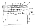
図1は本発明の第1の実施の形態に係わる差込み型継手の半断面図で、接続管を継手内部に挿入する前の状態を示す図であり、図2(a)は抜止リングの斜視図、図2(b)は同左側面図(b)、図2(c)は同正面図である。
(First embodiment)
Hereinafter, embodiments of the present invention will be described with reference to the drawings.
FIG. 1 is a half sectional view of a plug-in type joint according to a first embodiment of the present invention, showing a state before a connecting pipe is inserted into the joint, and FIG. 2 (a) is a perspective view of a retaining ring. FIG. 2B is a left side view of the same, and FIG. 2C is a front view of the same.
図1に示すように、差込み型継手(以下、単に継手ということがある。以下同様)1は、環状の仕切部21とその両側に形成された円筒部22を有する継手本体2と、円筒部22の外周側に差込まれる樹脂管10により押圧される抜止リング3a、3b及びOリング4a、4bを備えている。この継手1は、仕切部21を挟んで対称の構造を有するもので、各部の詳細は一方の側についてのみ説明し、他方の側(図1の反対側)の説明は省略する。
As shown in FIG. 1, a plug-in type joint (hereinafter simply referred to as a joint; hereinafter the same) 1 includes a
継手本体2の円筒部22の仕切部21側には段部があり、図1に示すように、その外周面に端部に向かって、外周がエッジ状に形成された係止部221と、1条の円周溝222aと2条の円周溝223a、223bが形成されている。また、手前の挿入口の内径側は外側に広がるテーパ状となっている。円周溝222aの幅は、ここでは抜止リング3a、3bが並んで装着可能な寸法に設定される。2条の円周溝223a、223bには、弾性体(例えばEPDM等のオレフィン系ゴム)からなるOリング4a、4bが嵌装されている。抜止リング3a、3bとOリング4a、4bの外径は下記する接続管の内径より大きいものである。また、継手本体2には、係止部221の外径より小さな内径を有する保護キャップ5がここでは締りバメによって嵌着固定されている。更に、係止部221は、複数のエッジ状部が外周面に端部に向かって形成(不図示)されていても良く、このような構成にすることで固着強度を高めることができる。例えば継手本体を樹脂で形成した場合には特に有効である。
There is a stepped portion on the
図2に示すように、抜止リング3a(3b)は、例えば耐食性を有する金属材料(SUS304等のオーステナイト系ステンレス鋼など)で形成され、縮径可能とするために、円周方向の途中に切り溝34が設けられ、一端側から他端側に向かって連続的に拡径された略C字状の部材である。抜止リング3a(3b)には、複数(図2の例では8個)の凸部31と複数(図2の例では7個)の凹部が円周方向に沿って交互に並ぶように形成されている。各凸部31は外周縁にエッジ部311を有するとともに、各凸部31の一方の端部は斜めに折曲げられて折曲部312a、312b、312c、312dが形成されている。
As shown in FIG. 2, the retaining
上記の各部品を用いて、次の手順で継手1が組立てられる。予め、継手本体2の円筒部22に形成された円周溝222aに抜止リング3a、3bが嵌装されるとともに、円周溝223a、223bにOリング4a、4bが嵌装される。次いで、円筒部22の外周に隙間を介して保護キャップ5が被せられ、その内周面が係止部221に圧入されることにより固着して、継手1が組立てられる。尚、保護キャップ5の固着手段としては、本例のような圧入の他にねじを用いた螺合、接着剤を用いた接着、溶接や摩擦圧着等による融着などを用いることが出来る。本発明ではこれらの手段を含めて固着と呼んでいる。このことは以下の実施態様でも同様である。
The joint 1 is assembled by the following procedure using each of the above components. The retaining rings 3a and 3b are fitted in the
図1に示す継手1によれば、保護キャップ5と円筒部22との隙間に樹脂管10を差込むだけの操作で、樹脂管10同士を接続することができる。詳述すると、樹脂管10が矢印X方向に奥まで差込まれ、その先端が係止部221の端面に当接することにより、配管接続が完了する。樹脂管10が差込まれる過程で、樹脂管10の内周面に押圧されてOリング4a、4bが圧縮されることにより、樹脂管10と継手本体2とが確実にシールされる。さらに樹脂管10の内周面が抜止リング3a、3bを押え付けることにより、抜止リング3a、3bが縮径して、その外周に形成されたエッジ部311が樹脂管10の内周面に食い込み、樹脂管10が継手本体2に強固に固着される。しかも、抜止リング3aの折曲部312a〜312dが継手本体1の円周溝222aの内壁部222bに引掛り(係止される)、かつ、抜止リング3bの折曲部312a〜312dが抜止リング3aに引掛る(係止される)ことにより、接続管10が継手本体1に差込まれた時に抜止リング3a及び3bが継手本体1の奥側にずれ込むことが防止される。また、上記と同様の手順で、仕切部21の他方の側に形成された円筒部(不図示)にも樹脂管を接続することができる。このように本実施の形態によれば、少ない部品点数(4点)で、継手に接続管を速やかに、かつシール性を保って強固に接続することが可能となる。特に手前側の2つのOリング4a、4bによりシール性が保証され、奥側の2つの抜止リング3a、3bにより引抜き阻止力の高い接続が保証される。
According to the joint 1 shown in FIG. 1, the
(第2の実施の形態)
図3は本発明の第2の実施の形態に係わる継手の一方の端部を示す半断面図であり、図1と同一機能部分は同一の参照符号で示す。
(Second Embodiment)
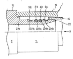
FIG. 3 is a half sectional view showing one end portion of the joint according to the second embodiment of the present invention, and the same functional parts as those in FIG. 1 are denoted by the same reference numerals.
図3に示す差込み型継手1は、環状の仕切部21と円筒部22を有する継手本体2と、円筒部22の外周側に差込まれる樹脂管10により押圧される抜止リング3a、3b及びOリング4a、4b、これらを取り囲む保護キャップ5を備えている点では、図1の継手と同様である。但し、図3の継手1は、継手本体2の円筒部22には、4条の円周溝222a、222c、223a、223bが形成されるとともに、円周溝222a、222cの幅は、抜止リング3a(3b)が装着可能な寸法に設定されている。即ち、この実施態様では抜止リング3a、3bがOリング4a、4bを挟むようにして装着されている点で、図1に示す継手本体と異なる。
A plug-in type joint 1 shown in FIG. 3 includes a
上記の継手1は、図1の場合と同様の手順で組立てられる。すなわち、継手本体2の円筒部22に形成された円周溝222a、222cに抜止リング3a、3bが嵌装されるとともに、円周溝223a、223bにOリング4a、4bが嵌装される。次いで、円筒部22の外周に隙間を介して保護キャップ5が被せられ、その内周面が係止部221に圧入されることにより固着され、継手1が組立てられる。
The joint 1 is assembled in the same procedure as in FIG. That is, the retaining rings 3a and 3b are fitted in the
図3に示す継手1によれば、図1の場合と同様に保護キャップ5と円筒部22との隙間に樹脂管10を差込むだけの操作で、樹脂管10同士を接続することができる。詳述すると樹脂管10が矢印X方向に奥まで差込まれ、その先端が係止部221の端面に当接することにより、配管接続が完了する。樹脂管10が差込まれる過程で、抜止リング3bを押え付けることにより、抜止リング3bが縮径して、その外周に形成されたエッジ部311が樹脂管10の内周面に食い込み、次いで樹脂管10の内周面がOリング4a、4bが縮径されることにより、樹脂管10と継手本体2とが確実にシールされ、さらに樹脂管10の内周面が抜止リング3aを押え付けることにより、抜止リング3aが縮径して、その外周に形成されたエッジ部311が樹脂管10の内周面に食い込み、樹脂管10が継手本体2に強固に固着される。また、上記と同様の手順で、仕切部21の他方の側に形成された円筒部(不図示)にも樹脂管を接続することができる。このように本実施の形態によれば、少ない部品点数(4点)で、継手に接続管を速やかにかつ強固に接続することが可能となる。特に抜止リング3aが接続管の奥側に食い込み、抜止リング3bが接続管の手前側に食い込むので前後に引抜き阻止力が働きより強固な接続が得られる。また、抜止リング3a、3bがOリング4a、4bを挟むようにして装着したことにより、樹脂管10に引抜き外力が加わった時、食い込み部を分散し樹脂管10の食いちぎりを防止し、引抜き阻止力の向上を図ることができる。
According to the joint 1 shown in FIG. 3, the
(第3の実施の形態)
図4は本発明の他の実施の形態に係わる継手の一方の端部を示す半断面図であり、図1と同一機能部分は同一の参照符号で示す。図5は抜止リングを示す図で、(a)は抜止リングの斜視図、(b)は同左側面図、(c)は同正面図である。
(Third embodiment)
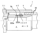
FIG. 4 is a half sectional view showing one end of a joint according to another embodiment of the present invention, and the same functional parts as those in FIG. 1 are denoted by the same reference numerals. 5A and 5B are views showing the retaining ring, wherein FIG. 5A is a perspective view of the retaining ring, FIG. 5B is a left side view thereof, and FIG. 5C is a front view thereof.
図4に示す差込み型継手1は、環状の仕切部21とその両側に形成された円筒部22を有する継手本体2と、円筒部22の外周側に差込まれる樹脂管10により押圧される抜止リング3c及びOリング4a、4bを備えている。但し図4に示す継手1は、継手本体2の円筒部22には、3条の円周溝222a、223a、223bが形成されるとともに、円周溝222aの一端側に、それより深くかつ狭幅の円周溝222dが形成されている点で、図1に示す継手と異なる。
The plug-in joint 1 shown in FIG. 4 is a retaining body pressed by a
図5に示すように、抜止リング3cは、弾性変形(縮径)を可能とするために、円周方向の途中に切り溝34が設けられ、一端側から他端側に向かって連続的に拡径された略C字状の部材である。抜止リング3a(3b)には、円周方向に沿って交互に、外周にエッジ部311を有する凸部31と凹部32が形成されるとともに、抜止リング3cの内径側は半径方向に折曲げられてフランジ部33が形成されている。
As shown in FIG. 5, the retaining ring 3 c is provided with a
上記の継手1の組立て手順は、図1の場合と同様である。まず、継手本体2の円筒部22に形成された円周溝222aに抜止リング3cが嵌装されるとともに、円周溝222dに抜止リング3aのフランジ部33が挿入されることにより、抜止リング3cが継手本体2に装着される。また円周溝223a、223bにOリング4a、4bが嵌装される。次いで、円筒部22の外周に隙間を介して保護キャップ5が被せられ、その内周面が係止部221に圧入されることにより固着され、継手1が組立てられる。
The procedure for assembling the joint 1 is the same as in FIG. First, the retaining ring 3c is fitted into the
図4に示す継手1によれば、保護キャップ5と円筒部22との隙間に樹脂管10を差込むだけの操作で、樹脂管10同士が接続される。すなわち樹脂管10が矢印X方向に奥まで差込まれ、その先端が仕切部21の端面に当接することにより、配管接続が完了する。樹脂管10が差込まれる過程で、樹脂管10の内周面がOリング4a、4bが縮径されることにより、樹脂管10と継手本体2とが確実にシールされ、さらに樹脂管10の内周面が抜止リング3cを押え付けることにより、抜止リング3cが縮径して、その外周に形成されたエッジ部311が樹脂管10の内周面に食い込み、樹脂管10が継手本体2に強固に固着される。また、抜止リング3cのフランジ部3cが継手本体1の円周溝222dに係止されることにより、接続管10が継手本体1に差込まれた時に抜止リング3cが継手本体1の奥側にずれ込むことが防止される。このように本実施の形態によれば、少ない部品点数(4点)で、継手に接続管を速やかにかつ強固に接続することが可能となる。尚、フランジ部3cは内径方向に突出するように形成しているが、これを水平方向延びるエッジ状に設けて円周溝222dを設けることなく、円周溝222aの手前側の端面にエッジ部を食い込ませるように係止させて抜止リング3cの移動を阻止する構造をとることも出来る。
According to the joint 1 shown in FIG. 4, the
(第4の実施の形態)
図6は本発明の他の実施の形態に係わる継手の一方の端部を示す半断面図であり、上記した例と同一機能部分は同一の参照符号で示す。図7、図8、図9及び図10はシール部材の断面を示す断面図である。
(Fourth embodiment)
FIG. 6 is a half sectional view showing one end of a joint according to another embodiment of the present invention, and the same functional parts as those in the above-described example are indicated by the same reference numerals. 7, 8, 9 and 10 are cross-sectional views showing a cross section of the seal member.
図6に示す差込み型継手1は、環状の仕切部21とその両端に形成された円筒部22を有する継手本体2と、円筒部22の外周側に差込まれる例えばPB(ポリブテン)で形成された樹脂管10により押圧される抜止リング3cと円筒部22の外側で隙間を介して固着される保護キャップ5を備えている。抜止リング3cはフランジ部付きで円周溝222aとそれより深い円周溝222dに装入されている。この継手1では、円筒部22に円周溝223cが形成され、ここに装着されるシール部材4cが上述の例とは異なる。
この継手1の組立て手順は上記の例と同様である。まず、継手本体2の円筒部22に形成された段付き円周溝222a、222dに抜止リング3cとフランジ部が嵌装されるとともに、例えば2条のシール部材4cを嵌装できる幅広の円周溝223cにシール部材4c(4d、4e、4f)が嵌装される。次いで、円筒部22に隙間を介して保護キャップ5が被せられ、その内周面が係止部221に圧入固着されて継手1が組立てられる。
The plug-in joint 1 shown in FIG. 6 is formed of a
The assembly procedure of the joint 1 is the same as the above example. First, the retaining ring 3c and the flange portion are fitted in the stepped
本例のシール部材は、図6、図7に示すように上述の例のOリング4a、4bを一体化したものと考えられ、形状も類似している。しかし図7に示すようにシール部材4cの断面形状は、樹脂管の内周面をシールする外側は比較的鋭角な山が2個連なった形状となし樹脂管の挿入がし易く且つOリング2個分のシールが働くようになしている。これに対し、円周溝223c内に装着される内側はOリング状の曲面を残し、据わりが良く管挿入時には円周溝内を埋めて密着し易い形状としている。
As shown in FIGS. 6 and 7, the seal member of this example is considered that the O-
また、図8〜図10はシール部材の変形例を示し、図8に示すシール部材4dは3個のOリングを一体化したものに類似しており、外側は3山が連なった形状となし内側は平坦に形成している。図9のシール部材4eは外側と内側の両方とも2山が連なった凸形状をなしている。図10のシール部材4fの外側は3山が連なった形状となし、内側は3つの円弧状の凸部を連ねた形状となしたものである。
このように本発明においてシール部材は、通常のOリングを単数あるいは複数個用いても良いし、また上記のようにシール機能はOリング複数個分を残しながら一体化して部品点数を減らすこともできる。シール部材による接続管内周面のシール機能は複数個所に備えていることが望ましいが、接続管の挿入方向に沿って手前側に抜止リングを設けた場合は、その後にOリング等のシール部材を複数個設けることが良い。そして、挿入方向の奥側には抜止リングを少なくとも1つ装着した構成とする。
8 to 10 show modified examples of the seal member. The seal member 4d shown in FIG. 8 is similar to an integrated three O-rings, and the outside has a shape in which three peaks are connected. The inside is formed flat. The seal member 4e in FIG. 9 has a convex shape in which two ridges are continuous on both the outer side and the inner side. The outer side of the seal member 4f in FIG. 10 has a shape in which three peaks are connected, and the inner side has a shape in which three arc-shaped convex portions are connected.
As described above, in the present invention, the sealing member may use one or a plurality of ordinary O-rings, and as described above, the sealing function may be integrated while leaving a plurality of O-rings to reduce the number of parts. it can. It is desirable that the sealing member has a sealing function for the inner peripheral surface of the connection pipe at a plurality of locations. However, when a retaining ring is provided on the near side along the insertion direction of the connection pipe, a sealing member such as an O-ring is provided thereafter. It is preferable to provide a plurality. And it is set as the structure which attached at least 1 retaining ring in the back | inner side of the insertion direction.
(第5の実施の形態)
図11は本発明の実施の形態に係わる差込み型継手の半断面図で、樹脂管を継手内部に挿入する前の状態を示す図であり、図12は加圧リングの斜視図、図13は図11の一部を拡大した断面図、図14は本発明の実施の形態に係わる継手に奥まで樹脂管が挿入された状態を示す半断面図である。
(Fifth embodiment)
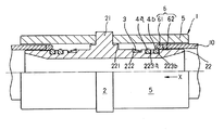
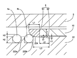
FIG. 11 is a half sectional view of the plug-in joint according to the embodiment of the present invention, showing a state before the resin pipe is inserted into the joint, FIG. 12 is a perspective view of the pressure ring, and FIG. 11 is an enlarged cross-sectional view of a part of FIG. 11, and FIG. 14 is a half cross-sectional view showing a state where the resin pipe is inserted into the joint according to the embodiment of the present invention.
図11に示すように、この実施の形態の差込み型継手1は、環状の仕切部21とその両側に形成された円筒部22を有する継手本体2と、円筒部22の外周側に差込まれる、例えばPE(ポリエチレン)で形成された樹脂管10により押圧される抜止リング3及びOリング4a、4bと、円筒部22に隙間を介して固着される保護キャップ5と、保護キャップ5と円筒部22との間に配設される加圧リング6を備えている。この継手1は、仕切部21を挟んで対称の構造を有するもので、各部の詳細は一方の側についてのみ説明し、他方の側(仕切部21の左側)の説明は省略する。
As shown in FIG. 11, the plug-in joint 1 of this embodiment is inserted into a
継手本体2の円筒部22には、図11に示すように、その外周面に端部に向かって、外周がエッジ状に形成された係止部221と、1条の円周溝222と2条の円周溝223a、223bが形成されている。円周溝222の幅は、抜止リング3が装着可能な寸法に設定される。また、2条の円周溝223a、223bには、弾性体(例えばEPDM等のオレフィン系ゴム)からなるOリング4a、4bが嵌装されている。さらに接続管10の挿入方向に向かって円周溝223bの手前に、上り勾配となる保持溝224(図13参照)が形成されている。
As shown in FIG. 11, the
抜止リング3は、上記第1の実施態様で用いた図2に示した抜止リングと同じものを用いれば良い。例えば耐食性を有する金属材料(SUS304等のオーステナイト系ステンレス鋼など)で形成され、縮径可能とするために、円周方向の途中に切り溝34が設けられ、一端側から他端側に向かって連続的に拡径された略C字状の部材である。抜止リング3には、複数の凸部31と複数の凹部が円周方向に沿って交互に並ぶように形成されている。各凸部31は外周縁にエッジ部311を有するとともに、各凸部31の一方の端部は斜めに折曲げられて折曲部312a、312b、312c、312dが形成されている。あるいは上述した図4、図5に示したフランジ付きの抜止リング3cを用いてもよい。
The retaining
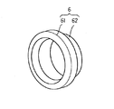
次に、図12及び図13に示すように、加圧リング6は、弾性体(例えばポリエチレン等の軟質樹脂)で形成され、樹脂管10(図11参照)の端面に当接し、先端側が断面円弧状に形成され、かつ樹脂管10と同等の外径を有する第1加圧部61と、その内径側から延出し樹脂管10の端部内周面に入り込むことができる薄肉リング状の第2加圧部62からなる。加圧リング6は、第1加圧部61がOリング4a(4b)を押え付けた時にその復元力により上向きに撓もうとするが、第2加圧部62が形成されているので、跳ね上がりを大幅に抑制することができる。この場合、第2加圧部62の厚さt1は、厚すぎると第1加圧部61の弾性変形が少なくなり、薄すぎると第1加圧部61が大きく撓むので、樹脂管10の厚さtの0.1〜0.25倍の範囲にあることが好ましい。
Next, as shown in FIGS. 12 and 13, the
継手本体2の円筒部22には、円周溝223bの手前に上記の加圧リング6が嵌装される保持溝224が形成されている(図13参照)。保持溝224の底面は、円周溝223bに向かって上り勾配になるようなテーパ形状を有することが好ましい。この形状であると、加圧リング6を円筒部22の所定位置に支持することが容易となり、また樹脂管10の端面で押し込まれた加圧リング6がOリング4a、4bを容易に乗り越えることができる。この場合、保持溝224の根元部における深さh1は、樹脂管10が保護キャップ5と円筒部22との隙間に挿入される過程でその先端が第2加圧部62の端部に引掛かるのを防止するために、第2加圧部62の厚さt1より大きな値に設定されることが好ましい。段差部224の長さL3は、加圧部61の長さL1と環状部62の長さL2の和よりもやや短くなるように設定することが好ましい。なお、加圧リング6のスライドを容易にするために、第2加圧部62には、円周方向の1箇所以上に切込みを設けることができる。
The
樹脂管10と継手本体2の円筒部22との間を確実にシールするために、シール溝223a、223bの溝深さh2は、Oリング4a、4bの一部がシール溝からはみ出すような寸法に設定される。Oリング4a、4bの突出高さh3は、通常円周溝223a、223bの深さh2の10〜30%の範囲に設定される。
In order to securely seal between the
上記の継手1は、次の手順で組立てられる。まず、継手本体2の円筒部22に形成された円周溝222に抜止リング3が嵌装されるとともに、円周溝223a、223bにOリング4a、4bが嵌装される。また円筒部22の外周面に形成された保持溝224(図13参照)に加圧リング6が嵌装される。次いで、円筒部22に隙間を介して保護キャップ5が被せられ、その内周面が係止部221に圧入されることにより固着して、継手1が組立てられる。
The joint 1 is assembled by the following procedure. First, the retaining
図11に示す継手1によれば、保護キャップ5と円筒部22との隙間に樹脂管10を差込むだけの操作で、樹脂管10同士を接続することができる。すなわち、樹脂管10が矢印X方向に差込まれ、その先端が係止部221の端面に当接することにより、配管接続が完了する(図14参照)。詳述すると、樹脂管10が差込まれることにより、加圧リング6の第2加圧部62が接続管10に内接する状態となり(図13参照)、次いで加圧リング6がOリング4a、4bに乗り上げ、Oリング4a、4bは第1加圧部61で圧縮され、引き続いて第2加圧部62で押え込まれる。これによりOリング4a、4bはその全体がシール溝223a、223bに収容されて、樹脂管10と継手本体2とが確実にシールされる。さらに樹脂管10の内周面が抜止リング3を押え付けることにより、抜止リング3が縮径して、その外周に形成されたエッジ部311が樹脂管10の内周面に食い込み、樹脂管10が継手本体2に強固に接続される。また上記と同様の手順で、仕切部21の他方の側に形成された円筒部(不図示)にも樹脂管を接続することができる。
According to the joint 1 shown in FIG. 11, the
上記のように本実施の形態によれば、少ない部品点数(5点)で、継手に接続管を速やかにかつ強固に接続することが可能となる。この場合、Oリング4a、4bは、その外径が10〜30%程度減少し、従来の1.5〜3倍程度の圧縮代が得られることが確認された。したがって、Oリング4a、4bはその全体がシール溝内に収容されるため、樹脂管10の内周に例えば20〜50μmの高さの縦筋が存在しても、流体の漏れを確実に防止することができる。
As described above, according to the present embodiment, the connecting pipe can be quickly and firmly connected to the joint with a small number of parts (5 points). In this case, it was confirmed that the outer diameters of the O-
また本実施の形態によれば、加圧リング6は容易に弾性変形するので、樹脂管10がかなり斜めに切断されていても、Oリング4a、4bの損傷を伴わずに継手本体2に挿入することができる。さらに樹脂管の切断時に管の端面が扁平形状になり、内径側に部分的に変形する、あるいは管の端面にバリやかえりが生じた場合でも、Oリング4a、4bの損傷を伴わずに樹脂管10を継手本体2に挿入することができる。
尚、本実施の形態で用いた加圧リングを上述した実施の形態で用いて良いことは無論である。同様に以下の実施の形態で用いても良い。これらの実施の形態を適宜複合的に用いることにより効果も複合的に得られるので望ましい。
Further, according to the present embodiment, since the
Of course, the pressure ring used in the present embodiment may be used in the above-described embodiment. Similarly, it may be used in the following embodiments. It is desirable to use these embodiments in an appropriate composite because the effects can be obtained in a composite manner.
(第6の実施の形態)
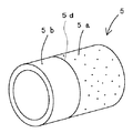
図15は本発明の実施の形態に係わり保護キャップを透明にした差込み型継手の半断面図で、保護キャップ5の外周面に凹状の差込み確認用の目盛70を形成した状態を示す図である。図16は同じく本発明の実施の形態に係わる継手の半断面図で、保護キャップの外周面に凸状の差込み確認用の目盛71を形成した状態を示す図である。図17は同じく保護キャップ5の外周面に凹状の目盛72を形成し、前記凹部72の拡大図も示し、また、前記凹部を不透明にするために微細な凹凸を形成した状態を示す。図18は半透明部5aと透明部5bの境界部を有す保護キャップ5の斜視図である。
(Sixth embodiment)
FIG. 15 is a half cross-sectional view of a plug-in joint with a protective cap made transparent according to the embodiment of the present invention, and shows a state in which a concave
図15に示すように、この実施の形態の差込み型継手1は、環状の仕切部21とその両端に形成された円筒部22を有する継手本体2と、円筒部22の外周側に差込まれ、例えば、PB(ポリブテン)で形成された樹脂管10により押圧される抜止リング3a及びOリング4a、4bと、円筒部22の端部外周に隙間を介して固着される保護キャップ5を備えている。この継手1は、仕切部21を挟んで対称の構造を有するもので、各部の詳細は一方の側についてのみ説明し、他方の側(仕切部21の左側)の説明は省略する。
As shown in FIG. 15, the plug-in joint 1 of this embodiment is inserted into a
この継手1も上記した実施例と同様に、継手本体2の円筒部22の端部には段差があり、その外周面に端部に向かって、外周がエッジ状に形成された係止部221と、溝222aと222dで形成される1条の段付き円周溝とOリングを嵌装する2条の円周溝223a、223bが形成されている。円周溝222aと222dの幅は、抜止リング3aが装着可能な寸法に形成される。第3の実施形態の図4と同様にフランジ部を有する抜止リング3aのフランジ33は2段の円周溝の下段側222dに設置され、樹脂管10の挿入時に抜止リング3aの樹脂管挿入方向へのはずれ込み防止に効果がある。また、2条の円周溝223a、223bは、弾性体(例えばEPDM等のオレフィン系ゴム)からなるOリング4a、4bが嵌装されている。
上記の継手1は、次の手順で組立てられる。まず、継手本体2の内筒部22に形成された段付き円周溝222a、222dに抜止リング3aが嵌装されるとともに、円周溝223a、223bにOリング4a、4bが嵌装される。次いで、円筒部22に隙間を介して保護キャップ5が被せられ、その円周面が係止部221に圧入されることにより固着され、継手1が組立てられる。
Similarly to the above-described embodiment, the joint 1 also has a step at the end of the
The joint 1 is assembled by the following procedure. First, the retaining
ここで、本例では図15に示す保護キャップ5は、透明又は半透明の樹脂製であり、この保護キャップ5は、外周面に凹状目盛70が形成されている。この目盛70は透明又は不透明な樹脂等で形成することが好ましく、また、射出成形等で形成される場合、凹状の差込み確認用目盛70の底部は平坦であることが好ましい。
Here, in this example, the
また別の実施例として図16に示すように、透明又は半透明の樹脂製の保護キャップ5の外周面に凸状目盛71を形成し、この目盛71は着色又は不透明な樹脂等で形成することが好ましい。また、凸状又は凹状溝の目盛70,71は、保護キャップ5の内周面に形成されていてもよい(不図示)。
これらの目盛70、71は、2条に形成されることが好ましい(不図示)。こうした場合、樹脂管10の先端が2条の目盛例えば70(71でも可)の間に挿着されていれば、樹脂管10の挿着(施工)は正常に完了していることが、継手の外部から目視で確認し易いからである。
As another example, as shown in FIG. 16, a convex scale 71 is formed on the outer peripheral surface of a
These
また別の実施例として図17に示すように、保護キャップ5の外周面の凹状目盛72は、切削加工等で凹凸状に形成されていてもよい。前記凹部に溝加工後の凹凸が形成されている状態を示す。また、前記の切削加工等の方法であれば前記保護キャップ5の内周面に凹状目盛72を形成し易いので都合がよい。
As another example, as shown in FIG. 17, the concave scale 72 on the outer peripheral surface of the
また別の実施例として図18に示すように、保護キャップ5について不透明な部分5aと透明な部分5bを形成し、この不透明な部分5aと透明な部分5bの境界線5dを目盛の代わりとしてもよい。例えば図18の不透明な部分5aと透明な部分5bを有する保護キャップ5の透明側5bを図17の係止部221に固着し、樹脂管10を継手21のX方向から挿入した場合、樹脂管10の姿が透明側5bに現れると、挿着(施工)が正常に完了していることが、目視により継手外部から確認できる。
また、上述の第6の実施形態で用いた加圧リングを目立つ色に着色しておけば目視確認がより容易になる。
As another embodiment, as shown in FIG. 18, the
Further, if the pressure ring used in the above-described sixth embodiment is colored in a conspicuous color, the visual confirmation becomes easier.
(第7の実施の形態)
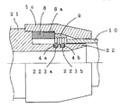
この実施の形態の差込み型継手は、図19に示すように環状の仕切部21とその両端に形成された円筒部22を有する継手本体2と、円筒部22の外周側の2条の凹溝223a、223bに嵌装したOリング4a、4bと、環状の仕切部21に固着した保護キャップを有しており、この例では継手本体に螺合する透明ナット5cとしている。そして、この透明ナット5cは目盛8a付きスリーブ8と、抜止部材9を内装しており、目盛8a付きスリーブ8は透明部であり一部を不透明部8aとしている。この目盛付きスリーブ8は継手本体21と当接し、さらに抜止部材9は目盛付きスリーブ8に当接している。すなわち、継手1奥側から樹脂管挿入口に向かって仕切部21、目盛付きスリーブ8、抜止部材9の順に構成されている。
上記の継手1は、次の手順で組立てられる。まず、継手本体2の内筒部22に形成された2条の円周溝223a、223bにOリング4a、4bが嵌装される。次いで、円筒部22に目盛付きスリーブ8、抜止部材9を嵌め込み透明ナット5cを仕切部21に仮締め(例えば手締め)で螺合することにより、継手1が組立てられる。
(Seventh embodiment)
As shown in FIG. 19, the plug-in joint of this embodiment includes a
The joint 1 is assembled by the following procedure. First, O-
この継手1に接続管を挿入すると、前記スリーブ8の透明部と不透明部8aの直線状の境界線を目盛の代わりとしてもよい、スリーブ8の不透明部8aは樹脂管10挿入側に設置されているから、樹脂管10を継手1に施工後、継手1の外部から樹脂管10の先端が目視等で確認できれば、樹脂管10の挿入は正常に行われ、施工が正常に行われたことが施工完了後に確認できる。また、その後透明スリーブ5cをレンチ等で仕切部21に螺合すると透明スリーブ5cの内周テーパ面に押され、抜止部材9は縮径し、樹脂管10の外周面に食い込み係止される。
When a connecting pipe is inserted into the joint 1, the linear boundary line between the transparent portion and the opaque portion 8 a of the
以上の説明では、継手本体の両側に樹脂管が差込まれる形式の継手について述べたが、本発明はこれに限らず、継手本体の一方に樹脂管を差込み、継手本体の他方にネジ部を設け、このネジ部を相手側部材に螺合する構造を有する継手あるいは電気融着継手も考えられ、形状についてもT型、エルボ型等の形状等、継手本体の材質については、青銅等の金属又はエンプラ、ポリブテン、ポリエチレン等の樹脂等種々考えられることはもちろんである。 In the above description, the type of joint in which the resin pipe is inserted on both sides of the joint main body has been described. However, the present invention is not limited to this, and the resin pipe is inserted into one side of the joint main body and the screw portion is provided on the other side of the joint main body. A joint or an electrofusion joint having a structure in which the threaded portion is screwed to the mating member is also conceivable. The shape of the joint body, such as a T shape or an elbow shape, and the material of the joint body is a metal such as bronze. Of course, various resins such as engineering plastics, polybutene, and polyethylene are conceivable.
1:継手、2:継手本体、21:仕切部、22:円筒部、221:円周突起、222、222a、222c、222d、222e、223a、223b:円周溝、222b:内壁部、224:保持溝、3、3a、3b、3c:抜止リング、31:凸部、311:エッジ部、312、312a、312b、312c、312d:折曲部、32:凹部、33:フランジ部、34:切り溝、4a、4b:シール部材(Oリング)、4c、4d、4e、4f:シール部材、5:保護キャップ、5a:不透明保護キャップ、5b:透明保護キャップ、5c:透明ナット、5d:境界線、6:加圧リング、61:第1加圧部、62:第2加圧部、70:凹状目盛、71:凸状目盛、72:凹凸状目盛、8:透明スリーブ、8a:スリーブの目盛、9:抜止部材、10:樹脂管
1: Joint, 2: Joint body, 21: Partition part, 22: Cylindrical part, 221: Circumferential protrusion, 222, 222a, 222c, 222d, 222e, 223a, 223b: Circumferential groove, 222b: Inner wall part, 224:
Claims (5)
前記円筒部には、少なくとも前記加圧リングの第2加圧部が保持される保持溝を有し、かつその底面は前記シール部材に向かって上り勾配に形成されていることを特徴とする差込み型継手。 A joint body having a cylindrical portion on which the connecting pipe is sheathed, a substantially C-shaped retaining ring that bites into the connecting pipe, an elastically deformable seal member mounted on the outer periphery of the cylindrical portion, and an outer side of the cylindrical portion A protective cap fixed to the joint body, and a pressure ring made of an elastic body interposed between the protective cap and the cylindrical portion, and the pressure ring is an end surface of the connection pipe A first pressurizing part that abuts on the inner diameter side and a second pressurizing part that extends from the inner diameter side and is inserted into the inner peripheral surface of the end of the connecting pipe,
The cylindrical portion has a holding groove for holding at least the second pressure portion of the pressure ring, and a bottom surface thereof is formed in an upward slope toward the seal member. Mold joint.
5. The insertion type according to claim 4, wherein the scale of the protective cap has an annular shape, and a bottom surface or an upper surface is formed by a boundary line between a concave portion or a convex portion or a transparent portion and a colored portion or an opaque portion whose surface is roughened. Fittings.
Priority Applications (1)
| Application Number | Priority Date | Filing Date | Title |
|---|---|---|---|
| JP2011142772A JP5218924B2 (en) | 2004-09-21 | 2011-06-28 | Plug-in fitting |
Applications Claiming Priority (5)
| Application Number | Priority Date | Filing Date | Title |
|---|---|---|---|
| JP2004273798 | 2004-09-21 | ||
| JP2004273798 | 2004-09-21 | ||
| JP2004273800 | 2004-09-21 | ||
| JP2004273800 | 2004-09-21 | ||
| JP2011142772A JP5218924B2 (en) | 2004-09-21 | 2011-06-28 | Plug-in fitting |
Related Parent Applications (1)
| Application Number | Title | Priority Date | Filing Date |
|---|---|---|---|
| JP2005271547A Division JP2006118704A (en) | 2004-09-21 | 2005-09-20 | Insertion type joint |
Publications (2)
| Publication Number | Publication Date |
|---|---|
| JP2011185443A JP2011185443A (en) | 2011-09-22 |
| JP5218924B2 true JP5218924B2 (en) | 2013-06-26 |
Family
ID=44791958
Family Applications (1)
| Application Number | Title | Priority Date | Filing Date |
|---|---|---|---|
| JP2011142772A Active JP5218924B2 (en) | 2004-09-21 | 2011-06-28 | Plug-in fitting |
Country Status (1)
| Country | Link |
|---|---|
| JP (1) | JP5218924B2 (en) |
Families Citing this family (2)
| Publication number | Priority date | Publication date | Assignee | Title |
|---|---|---|---|---|
| JP2020094664A (en) * | 2018-12-14 | 2020-06-18 | 株式会社ブリヂストン | Pipe joint |
| CN114673840B (en) * | 2022-02-25 | 2023-09-19 | 安徽宝立华机械设备有限公司 | High-pressure sealing joint and connecting method thereof |
Family Cites Families (6)
| Publication number | Priority date | Publication date | Assignee | Title |
|---|---|---|---|---|
| JPS5220018Y2 (en) * | 1972-05-22 | 1977-05-09 | ||
| JP3672657B2 (en) * | 1996-02-29 | 2005-07-20 | 株式会社リケン | Plug-in fitting |
| JP4114894B2 (en) * | 1998-04-30 | 2008-07-09 | シーケー金属株式会社 | Resin coated joint |
| JP4474043B2 (en) * | 2000-06-30 | 2010-06-02 | Jfe継手株式会社 | Plug-in type fittings and methods for inserting pipes into plug-in type fittings |
| DE10158208B4 (en) * | 2001-11-28 | 2006-03-09 | Friatec Ag | plug-in coupling |
| JP4460838B2 (en) * | 2003-01-29 | 2010-05-12 | Jfe継手株式会社 | Plug-in fittings |
-
2011
- 2011-06-28 JP JP2011142772A patent/JP5218924B2/en active Active
Also Published As
| Publication number | Publication date |
|---|---|
| JP2011185443A (en) | 2011-09-22 |
Similar Documents
| Publication | Publication Date | Title |
|---|---|---|
| JP2006118704A (en) | Insertion type joint | |
| US5484174A (en) | Pipe coupling and method of joining materials | |
| US6860523B2 (en) | Tube coupling | |
| US6595559B1 (en) | Pipe coupling | |
| TWI557353B (en) | Pipe fittings | |
| KR101254862B1 (en) | Pipe joint for plastic resin pipe | |
| JP2007198585A (en) | Easy release joint for resin tube | |
| JP4939826B2 (en) | How to assemble pipe fittings | |
| JP3156933U (en) | Structure of pipe for fluid flow path | |
| JP5218924B2 (en) | Plug-in fitting | |
| KR101267647B1 (en) | Pipe joint for a plastic resin pipe | |
| JP2011127647A (en) | Quick disconnection coupling for resin pipe | |
| JP4962849B2 (en) | Pipe fitting | |
| JP4416091B2 (en) | Structure of pipe for fluid flow path | |
| KR101344183B1 (en) | Transition fitting and connecting method therewith for gas pipes | |
| JP4597889B2 (en) | Pipe fitting | |
| JP5515495B2 (en) | Fitting | |
| JP2008232330A (en) | Fluid pipe joint | |
| GB2451628A (en) | Fluid pressure activated pipe coupling comprising folded sleeve secured by clamping rings | |
| JP5466999B2 (en) | Pipe fitting | |
| JP3959666B2 (en) | Sleeve type fitting | |
| JP2007170658A (en) | Pipe joint | |
| JP3859125B2 (en) | Sleeve type fitting | |
| JPH09152068A (en) | Attachment for thin wall stainless steel pipe and pipe joint | |
| JP2011202790A (en) | Method of connecting resin pipe to resin pipe joint, and the resin pipe joint |
Legal Events
| Date | Code | Title | Description |
|---|---|---|---|
| A621 | Written request for application examination |
Free format text: JAPANESE INTERMEDIATE CODE: A621 Effective date: 20110707 |
|
| A977 | Report on retrieval |
Free format text: JAPANESE INTERMEDIATE CODE: A971007 Effective date: 20130108 |
|
| TRDD | Decision of grant or rejection written | ||
| A01 | Written decision to grant a patent or to grant a registration (utility model) |
Free format text: JAPANESE INTERMEDIATE CODE: A01 Effective date: 20130208 |
|
| A61 | First payment of annual fees (during grant procedure) |
Free format text: JAPANESE INTERMEDIATE CODE: A61 Effective date: 20130221 |
|
| FPAY | Renewal fee payment (event date is renewal date of database) |
Free format text: PAYMENT UNTIL: 20160315 Year of fee payment: 3 |
|
| R150 | Certificate of patent or registration of utility model |
Ref document number: 5218924 Country of ref document: JP Free format text: JAPANESE INTERMEDIATE CODE: R150 Free format text: JAPANESE INTERMEDIATE CODE: R150 |
|
| S531 | Written request for registration of change of domicile |
Free format text: JAPANESE INTERMEDIATE CODE: R313531 |
|
| S533 | Written request for registration of change of name |
Free format text: JAPANESE INTERMEDIATE CODE: R313533 |
|
| R350 | Written notification of registration of transfer |
Free format text: JAPANESE INTERMEDIATE CODE: R350 |
