JP5218478B2 - Paper processing apparatus and image forming system - Google Patents
Paper processing apparatus and image forming systemInfo
- Publication number
- JP5218478B2 JP5218478B2 JP2010131828A JP2010131828A JP5218478B2 JP 5218478 B2 JP5218478 B2 JP 5218478B2 JP 2010131828 A JP2010131828 A JP 2010131828A JP 2010131828 A JP2010131828 A JP 2010131828A JP 5218478 B2 JP5218478 B2 JP 5218478B2
- Authority
- JP
- Japan
- Prior art keywords
- bundle
- sheet
- sheets
- sheet bundle
- binding
- Prior art date
- Legal status (The legal status is an assumption and is not a legal conclusion. Google has not performed a legal analysis and makes no representation as to the accuracy of the status listed.)
- Expired - Fee Related
Links
Images


Classifications
-
- B—PERFORMING OPERATIONS; TRANSPORTING
- B65—CONVEYING; PACKING; STORING; HANDLING THIN OR FILAMENTARY MATERIAL
- B65H—HANDLING THIN OR FILAMENTARY MATERIAL, e.g. SHEETS, WEBS, CABLES
- B65H37/00—Article or web delivery apparatus incorporating devices for performing specified auxiliary operations
- B65H37/04—Article or web delivery apparatus incorporating devices for performing specified auxiliary operations for securing together articles or webs, e.g. by adhesive, stitching or stapling
-
- B—PERFORMING OPERATIONS; TRANSPORTING
- B42—BOOKBINDING; ALBUMS; FILES; SPECIAL PRINTED MATTER
- B42C—BOOKBINDING
- B42C1/00—Collating or gathering sheets combined with processes for permanently attaching together sheets or signatures or for interposing inserts
- B42C1/12—Machines for both collating or gathering and permanently attaching together the sheets or signatures
-
- B—PERFORMING OPERATIONS; TRANSPORTING
- B65—CONVEYING; PACKING; STORING; HANDLING THIN OR FILAMENTARY MATERIAL
- B65H—HANDLING THIN OR FILAMENTARY MATERIAL, e.g. SHEETS, WEBS, CABLES
- B65H31/00—Pile receivers
- B65H31/24—Pile receivers multiple or compartmented, e.d. for alternate, programmed, or selective filling
-
- B—PERFORMING OPERATIONS; TRANSPORTING
- B65—CONVEYING; PACKING; STORING; HANDLING THIN OR FILAMENTARY MATERIAL
- B65H—HANDLING THIN OR FILAMENTARY MATERIAL, e.g. SHEETS, WEBS, CABLES
- B65H31/00—Pile receivers
- B65H31/30—Arrangements for removing completed piles
- B65H31/3027—Arrangements for removing completed piles by the nip between moving belts or rollers
-
- G—PHYSICS
- G03—PHOTOGRAPHY; CINEMATOGRAPHY; ANALOGOUS TECHNIQUES USING WAVES OTHER THAN OPTICAL WAVES; ELECTROGRAPHY; HOLOGRAPHY
- G03G—ELECTROGRAPHY; ELECTROPHOTOGRAPHY; MAGNETOGRAPHY
- G03G15/00—Apparatus for electrographic processes using a charge pattern
- G03G15/65—Apparatus which relate to the handling of copy material
- G03G15/6538—Devices for collating sheet copy material, e.g. sorters, control, copies in staples form
- G03G15/6541—Binding sets of sheets, e.g. by stapling, glueing
-
- B—PERFORMING OPERATIONS; TRANSPORTING
- B42—BOOKBINDING; ALBUMS; FILES; SPECIAL PRINTED MATTER
- B42B—PERMANENTLY ATTACHING TOGETHER SHEETS, QUIRES OR SIGNATURES OR PERMANENTLY ATTACHING OBJECTS THERETO
- B42B4/00—Permanently attaching together sheets, quires or signatures by discontinuous stitching with filamentary material, e.g. wire
-
- B—PERFORMING OPERATIONS; TRANSPORTING
- B42—BOOKBINDING; ALBUMS; FILES; SPECIAL PRINTED MATTER
- B42B—PERMANENTLY ATTACHING TOGETHER SHEETS, QUIRES OR SIGNATURES OR PERMANENTLY ATTACHING OBJECTS THERETO
- B42B5/00—Permanently attaching together sheets, quires or signatures otherwise than by stitching
-
- B—PERFORMING OPERATIONS; TRANSPORTING
- B65—CONVEYING; PACKING; STORING; HANDLING THIN OR FILAMENTARY MATERIAL
- B65H—HANDLING THIN OR FILAMENTARY MATERIAL, e.g. SHEETS, WEBS, CABLES
- B65H2301/00—Handling processes for sheets or webs
- B65H2301/40—Type of handling process
- B65H2301/43—Gathering; Associating; Assembling
- B65H2301/438—Finishing
- B65H2301/4382—Binding or attaching processes
- B65H2301/43828—Binding or attaching processes involving simultaneous deformation of at least a part of the articles to be bound
-
- B—PERFORMING OPERATIONS; TRANSPORTING
- B65—CONVEYING; PACKING; STORING; HANDLING THIN OR FILAMENTARY MATERIAL
- B65H—HANDLING THIN OR FILAMENTARY MATERIAL, e.g. SHEETS, WEBS, CABLES
- B65H2511/00—Dimensions; Position; Numbers; Identification; Occurrences
- B65H2511/30—Numbers, e.g. of windings or rotations
-
- B—PERFORMING OPERATIONS; TRANSPORTING
- B65—CONVEYING; PACKING; STORING; HANDLING THIN OR FILAMENTARY MATERIAL
- B65H—HANDLING THIN OR FILAMENTARY MATERIAL, e.g. SHEETS, WEBS, CABLES
- B65H2511/00—Dimensions; Position; Numbers; Identification; Occurrences
- B65H2511/40—Identification
- B65H2511/414—Identification of mode of operation
-
- B—PERFORMING OPERATIONS; TRANSPORTING
- B65—CONVEYING; PACKING; STORING; HANDLING THIN OR FILAMENTARY MATERIAL
- B65H—HANDLING THIN OR FILAMENTARY MATERIAL, e.g. SHEETS, WEBS, CABLES
- B65H2701/00—Handled material; Storage means
- B65H2701/10—Handled articles or webs
- B65H2701/13—Parts concerned of the handled material
- B65H2701/131—Edges
-
- B—PERFORMING OPERATIONS; TRANSPORTING
- B65—CONVEYING; PACKING; STORING; HANDLING THIN OR FILAMENTARY MATERIAL
- B65H—HANDLING THIN OR FILAMENTARY MATERIAL, e.g. SHEETS, WEBS, CABLES
- B65H2801/00—Application field
- B65H2801/24—Post -processing devices
- B65H2801/27—Devices located downstream of office-type machines
-
- G—PHYSICS
- G03—PHOTOGRAPHY; CINEMATOGRAPHY; ANALOGOUS TECHNIQUES USING WAVES OTHER THAN OPTICAL WAVES; ELECTROGRAPHY; HOLOGRAPHY
- G03G—ELECTROGRAPHY; ELECTROPHOTOGRAPHY; MAGNETOGRAPHY
- G03G2215/00—Apparatus for electrophotographic processes
- G03G2215/00362—Apparatus for electrophotographic processes relating to the copy medium handling
- G03G2215/00789—Adding properties or qualities to the copy medium
- G03G2215/00822—Binder, e.g. glueing device
- G03G2215/00848—Details of binding device
Description
本発明は、用紙処理装置、および画像形成システムに関する。 The present invention relates to a sheet processing apparatus and an image forming system.
画像形成システムとして、シート束に綴じ処理を行う複数の綴じ手段、例えば接着剤塗布手段、半抜き綴じ手段、ステープル綴じ手段、仮綴じ手段等を備えるものが存在する(特許文献1参照)。
また、用紙後処理システムとして、綴じ合わせることの難易度に応じて、複数の綴じ手段から綴じ手段を選択するものが存在する(特許文献2参照)。
さらに、書類綴じ装置として、シート紙の紙舌片を形成し、この紙舌片を刻み穴に挿入することにより綴じ過程を行うものが存在する。
Some image forming systems include a plurality of binding units that perform binding processing on a sheet bundle, for example, an adhesive application unit, a half-cut binding unit, a staple binding unit, and a temporary binding unit (see Patent Document 1).
Also, there is a paper post-processing system that selects a binding means from a plurality of binding means according to the difficulty of binding (see Patent Document 2).
Further, there is a document binding apparatus that forms a paper tongue piece of sheet paper and performs a binding process by inserting the paper tongue piece into a notch hole.
本発明は、複数の綴じ処理によって用紙束を綴じ得る用紙処理装置において、用紙束が搬送される際に用紙束の綴じられた部分が受ける損傷を抑制することを目的とする。 An object of the present invention is to suppress damage to a bound portion of a sheet bundle when the sheet bundle is conveyed in a sheet processing apparatus capable of binding the sheet bundle by a plurality of binding processes.
請求項1記載の発明は、用紙を揃えた状態で重ね合わせた用紙束として積載する積載手段と、積載手段上の用紙束を夫々第1綴処理により第1用紙束として綴じる第1綴手段及び、第2綴処理により第2用紙束として綴じる第2綴じ手段と、第1用紙束を搬送する際には前記積載手段から第1経路に向けて搬送し、第2用紙束を搬送する際には当該積載手段から当該第1経路とは逆方向の第2経路に向けて搬送する搬送手段とを備えたことを特徴とする用紙処理装置である。
請求項2記載の発明は、用紙を揃えた状態で重ね合わせた用紙束として積載する積載手段と、前記積載手段に積載された前記用紙束を第1の綴じ処理により第1の用紙束として綴じる第1の綴じ手段と、前記積載手段に積載された前記用紙束を第2の綴じ処理により第2の用紙束として綴じる第2の綴じ手段と、前記第1の用紙束を搬送する際には前記積載手段から第1経路に向けて搬送し、かつ前記第2の用紙束を搬送する際には当該積載手段から当該第1経路とは逆方向の第2経路に向けて搬送する搬送手段と、前記第2経路に配置され、前記第2の用紙束の上面側と下面側とを反転させて搬送する反転搬送手段と、前記第1経路に配置され、前記搬送手段によって搬送された前記第1の用紙束を配置させる第1の搬送束積載手段と、前記第2経路に配置され、前記反転搬送手段によって反転搬送された前記第2の用紙束を配置させる第2の搬送束積載手段とを備えたことを特徴とする用紙処理装置である。
請求項3記載の発明は、前記第2の用紙束が前記積載手段から前記第2経路へ搬送されることを妨げ、かつ前記第2の用紙束の搬送方向先端側となる端部と接して配置され当該端部を揃える端部揃え部を備え、前記端部揃え部が、前記第2の用紙束を前記積載手段から前記第2経路に搬送する際に、当該第2の用紙束が搬送されることを妨げない位置に移動することを特徴とする請求項2記載の用紙処理装置である。
請求項4記載の発明は、前記第2の綴じ手段は、前記用紙束の一部を変形させ、当該用紙束の各用紙における変形された箇所どうしが掛かり合うことによって、当該用紙束を綴じることを特徴とする請求項2または3記載の用紙処理装置である。
According to the first aspect of the present invention, a stacking unit that stacks a stack of sheets with the sheets aligned, a first binding unit that binds the sheet bundle on the stacking unit as a first sheet bundle by a first binding process, and A second binding unit that binds as a second sheet bundle by the second binding process; and when the first sheet bundle is conveyed, the second sheet bundle is conveyed from the stacking unit toward the first path, and the second sheet bundle is conveyed. Is a sheet processing apparatus comprising transport means for transporting from the stacking means toward a second path opposite to the first path.
According to a second aspect of the present invention, a stacking unit that stacks sheets stacked in a state where the sheets are aligned, and the sheet stack stacked on the stacking unit is bound as a first sheet bundle by a first binding process. A first binding unit, a second binding unit that binds the bundle of sheets stacked on the stacking unit as a second bundle of sheets by a second binding process, and when transporting the first bundle of sheets. A transporting means for transporting from the stacking means toward the first path and transporting the second sheet bundle from the stacking means toward a second path in a direction opposite to the first path; , A reversing conveying means arranged in the second path and conveying the second sheet bundle by reversing the upper surface side and the lower surface side thereof, and the first conveying means arranged in the first path and conveyed by the conveying means. First conveying bundle stacking means for arranging one sheet bundle, and the front Disposed in the second path, a sheet processing apparatus characterized by comprising a second conveying bundle stacking means for placing said inverted conveyed second sheet bundle by the reversal conveyance means.
According to a third aspect of the present invention, the second sheet bundle is prevented from being conveyed from the stacking means to the second path, and is in contact with an end portion on the leading end side in the conveyance direction of the second sheet bundle. An end aligning section that is arranged and aligns the end, and the second sheet bundle is conveyed when the end aligning section conveys the second sheet bundle from the stacking means to the second path. The sheet processing apparatus according to
According to a fourth aspect of the present invention, the second binding means binds the sheet bundle by deforming a part of the sheet bundle and engaging the deformed portions of the sheets in the sheets. a sheet processing apparatus according to
請求項5記載の発明は、前記第2の搬送束積載手段に配置された前記第2の用紙束は、前記変形された箇所である突出部が当該第2の用紙束の下面側となることを特徴とする請求項4記載の用紙処理装置である。
請求項6記載の発明は、前記第2の綴じ手段は、前記用紙束に切り込みを形成する切込部と、前記用紙束の一部を特定の形に切ることにより、一方の端部が当該用紙束と連続する部分を残す舌部を当該用紙束に形成する舌部形成部と、前記舌部を折り当該舌部の他方の端部を前記切り込みに挿入する切込挿入部とを有することを特徴とする請求項2乃至5のいずれか1項記載の用紙処理装置である。
請求項7記載の発明は、前記第2の搬送束積載手段に配置された前記第2の用紙束は、前記切り込みに挿入された前記他方の端部が当該第2の用紙束の下面側となることを特徴とする請求項6記載の用紙処理装置である。
請求項8記載の発明は、前記第1の綴じ手段は、ステープル針を用いて前記用紙束を綴じることを特徴とする請求項2乃至7のいずれか1項記載の用紙処理装置である。
請求項9記載の発明は、請求項1乃至8のいずれか1項記載の用紙処理装置と、用紙に画像を形成して前記用紙処理装置に向けて供給する画像形成装置とを含むことを特徴とする画像形成システムである。
According to a fifth aspect of the present invention, in the second sheet bundle disposed on the second transport bundle stacking unit, the protruding portion which is the deformed portion is on the lower surface side of the second sheet bundle. The sheet processing apparatus according to claim 4 .
According to a sixth aspect of the present invention, the second binding means includes: a notch portion that forms a cut in the sheet bundle; and a part of the sheet bundle is cut into a specific shape so that one end portion is A tongue forming portion for forming a tongue portion on the sheet bundle to leave a portion continuous with the sheet bundle, and a notch insertion portion for folding the tongue and inserting the other end of the tongue into the notch. a sheet processing apparatus according to any one of
According to a seventh aspect of the present invention, in the second sheet bundle disposed in the second transport bundle stacking unit, the other end inserted into the notch is on the lower surface side of the second sheet bundle. The sheet processing apparatus according to claim 6 .
The invention according to claim 8 is the sheet processing apparatus according to any one of
The invention according to claim 9 includes the sheet processing apparatus according to any one of
請求項1記載の発明によれば、本構成を有しない場合に比較して、複数の綴じ処理によって用紙束を綴じ得る用紙処理装置において、用紙束が搬送される際に用紙束の綴じられた部分が受ける損傷を抑制することができる。
請求項2記載の発明によれば、本構成を有しない場合に比較して、複数の綴じ処理によって用紙束を綴じ得る用紙処理装置において、用紙束が搬送される際に用紙束の綴じられた部分が受ける損傷を抑制することができる。
請求項3記載の発明によれば、本構成を有しない場合に比較して、用紙の端部をより確実に揃えることができる。
請求項4記載の発明によれば、本構成を有しない場合に比較して、用紙以外の部材を用いることなく用紙束に綴じ処理を施すことができる。
請求項5記載の発明によれば、本構成を有しない場合に比較して、用紙束が搬送される際に用紙束の綴じられた部分が受ける損傷をより抑制することができる。
請求項6記載の発明によれば、本構成を有しない場合に比較して、用紙以外の部材を用いることなく用紙の積載方向に圧力が加えられた際にも、用紙以外の部材を用いることなく綴じ力を維持することができる。
請求項7記載の発明によれば、本構成を有しない場合に比較して、用紙束が搬送される際に用紙束の綴じられた部分が受ける損傷をより抑制することができる。
請求項8記載の発明によれば、本構成を有しない場合に比較して、より強い綴じ力で綴じを施すことができる。
請求項9記載の発明によれば、本構成を有しない場合に比較して、複数の綴じ処理によって用紙束を綴じ得る画像形成システムにおいて、用紙束が搬送される際に用紙束の綴じられた部分が受ける損傷を抑制することができる。
According to the first aspect of the present invention, the sheet bundle is bound when the sheet bundle is conveyed in the sheet processing apparatus capable of binding the sheet bundle by a plurality of binding processes as compared with the case where the present configuration is not provided. Damage to the part can be suppressed.
According to the second aspect of the invention, as compared with the case not having the present structure, the sheet processing apparatus capable of binding a sheet bundle by a plurality of binding processing, the bound of the sheet bundle when the sheet bundle is conveyed Damage to the part can be suppressed.
According to the third aspect of the present invention, the end portions of the paper can be more reliably aligned as compared with the case where this configuration is not provided.
According to the invention described in claim 4, it is possible to perform the binding process on the sheet bundle without using a member other than the sheet as compared with the case where the present configuration is not provided.
According to the fifth aspect of the present invention, it is possible to further suppress damage to the bound portion of the sheet bundle when the sheet bundle is conveyed as compared with the case where the present configuration is not provided.
According to the sixth aspect of the present invention, the member other than the paper is used even when pressure is applied in the paper stacking direction without using a member other than the paper, as compared with the case where the present configuration is not provided. It is possible to maintain the binding force.
According to the seventh aspect of the present invention, as compared with a case where the present configuration is not provided, it is possible to further suppress damage to the bound portion of the sheet bundle when the sheet bundle is conveyed.
According to the eighth aspect of the present invention, binding can be performed with a stronger binding force than in the case where the present configuration is not provided.
According to the ninth aspect of the present invention, the sheet bundle is bound when the sheet bundle is conveyed in the image forming system capable of binding the sheet bundle by a plurality of binding processes as compared with the case without this configuration. Damage to the part can be suppressed.
以下、添付図面を参照して、本発明の実施の形態について詳細に説明する。
ここで、本実施の形態においては、複数の綴じ処理によって用紙束を綴じ得る用紙処理装置において、用紙束が搬送される際に用紙束の綴じられた部分が受ける損傷を抑制する手段として次の二つの構成について説明する。すなわち、用紙束に施された綴じ処理によって搬送路を分ける構成と、綴じ処理が施された部分をずらして排出する構成とに分けて説明する。
<画像形成システム1>
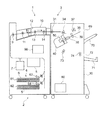
図1は、本実施の形態が適用される画像形成システム1を示す概略構成図である。図1に示す画像形成システム1は、例えば、電子写真方式によって画像を形成するプリンタや複写機等の画像形成装置2と、画像形成装置2によって例えばトナー像が形成された用紙Sに後処理を施す用紙処理装置3とを備えている。
Embodiments of the present invention will be described below in detail with reference to the accompanying drawings.
Here, in the present embodiment, in a sheet processing apparatus capable of binding a sheet bundle by a plurality of binding processes, the following means is used as a means for suppressing damage to the bound portion of the sheet bundle when the sheet bundle is conveyed. Two configurations will be described. That is, a description will be given separately for a configuration in which a conveyance path is divided by a binding process performed on a sheet bundle and a configuration in which a portion subjected to the binding process is shifted and discharged.
<
FIG. 1 is a schematic configuration diagram illustrating an
<画像形成装置2>
画像形成装置2は、画像が形成される用紙Sを供給する用紙供給部6と、用紙供給部6から供給された用紙Sに画像を形成する画像形成部5とを備える。また、画像形成装置2は、この画像形成部5で画像が形成された用紙Sの面を反転させる用紙反転装置7と、画像が形成された用紙Sを排出する排出ロール9とを備える。さらに、画像形成装置2は、ユーザから綴じ処理に関する情報を受け付けるユーザ・インターフェイス90を備えている。
用紙供給部6は、用紙Sを内部に積載しその用紙Sを画像形成部5に供給する第1の用紙供給用積載部61、および第2の用紙供給用積載部62を有する。また、用紙供給部6は、第1の用紙供給用積載部61の内部に備えられた用紙Sの有無について検知する第1の用紙供給用センサ63と、第2の用紙供給用積載部62の内部に備えられた用紙Sの有無を検知する第2の用紙供給用センサ64とを有する。
<
The
The sheet supply unit 6 includes a first sheet
<用紙処理装置3>
用紙処理装置3は、画像形成装置2から出力された用紙Sを更に下流側に搬送する搬送装置10と、例えば用紙Sを集めて束ねるコンパイル用積載部35や用紙Sの端部を綴じるステープラ40などを含む後処理装置30とを備えている。また、用紙処理装置3は、画像形成システム1全体を制御する制御部80を備えている。
用紙処理装置3の搬送装置10は、画像形成装置2の排出ロール9を介して出力される用紙Sを受け取る一対のロールである入口ロール11と、この入口ロール11にて受け取られた用紙Sに必要に応じて穴あけを施すパンチャ12とを備えている。また、搬送装置10は、パンチャ12のさらに下流側に、用紙Sを下流側へと搬送する一対のロールである第1搬送ロール13と、後処理装置30に向けて用紙Sを搬送する一対のロールである第2搬送ロール14とを有する。
<
The
The
用紙処理装置3の後処理装置30は、搬送装置10から用紙Sを受け取る一対のロールである受け取りロール31を備えている。また、後処理装置30は、受け取りロール31の下流側に設けられ用紙Sを複数枚集めて収容するコンパイル用積載部35と、コンパイル用積載部35に向けて用紙Sを排出する一対のロールであるエグジットロール34とを備えている。
また、後処理装置30は、用紙Sをコンパイル用積載部35のエンドガイド35b(後述)に向けて押し込むよう回転するパドル37を備えている。さらに、後処理装置30は、用紙Sの端部を揃えるためのタンパ38を備えている。さらにまた、後処理装置30は、コンパイル用積載部35にて集積された用紙Sを押さえ、かつ順方向あるいは逆方向に回転することにより、綴じられた用紙Sの束を下流側へ搬送するイジェクト(eject)ロール39を備えている。さらに、イジェクトロール39から搬送された用紙Sの束を、イジェクトロール39によって搬送された方向とは異なる方向に搬送する反転搬送ロール73と、反転搬送ロール73から搬送された用紙Sの束を排出するよう搬送する反転イジェクトロール74とを有する。
さらに、後処理装置30は、コンパイル用積載部35に集積された用紙Sの束の端部を、ステープル針41(後述)を用いて綴じるステープラ40と、ステープル針41を用いることなく用紙Sの束の端部を綴じる針無綴じ装置50とを備える。
さらにまた、後処理装置30は、用紙Sの束をイジェクトロール39によって後処理装置30の外側へ排出するための第1開口部69を備える。そして、第1開口部69から排出された用紙Sの束をユーザが取りやすいようにして積み重ねる第1スタッカ70を備える。さらにまた、後処理装置30は、第1開口部69の下方に、用紙Sの束を反転イジェクトロール74によって後処理装置30の外側へ排出するための第2開口部72を備える。そして、第1スタッカ70の下方に、第2開口部72から排出された用紙Sの束をユーザが取りやすいようにして積み重ねる第2スタッカ71を備える。
The
Further, the
Further, the
Furthermore, the
<綴じ手段周辺の構造>
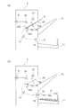
次に、図2及び図3を用いて、コンパイル用積載部35、およびその周囲に設けられるステープラ40および針無綴じ装置50等を説明する。ここで、図2は、コンパイル用積載部35周辺を示す概略構成図であり、図3は、図2の矢印III方向から見たコンパイル用積載部35周辺の概略構成図である。なお、図3における下側は、画像形成システム1のユーザ側を示し、図1および図2における紙面手前側を示す。また図3において、簡略化のためイジェクトロール39など一部の部材は図示されていない。
<Structure around the binding means>
Next, the
まず、積載手段の一例であるコンパイル用積載部35は、用紙Sを積載する上面を有する底部35aと、この底部35aの周囲に設けられるエンドガイド35bとを含む。
なお、詳しくは後述するが、コンパイル用積載部35周辺における用紙Sの動きは、まずコンパイル用積載部35に向けて供給され(図2の第1の進行方向S1参照)、次に進行方向を反転させてコンパイル用積載部35の底部35aに沿って落下する(図2の第2の進行方向S2参照)。その後、各用紙Sの端部が揃えられ、用紙Sの束を形成する。そして、この用紙Sの束は、コンパイル用積載部35の底部35aに沿ってさらに落下する方向に進行するか、あるいは進行方向を反転させてコンパイル用積載部35の底部35aに沿って上昇する(図2の第3の進行方向S3参照)。
First, the
As will be described in detail later, the movement of the sheet S around the compile stacking
さて、端部揃え部の一例であるエンドガイド35bは、底部35aに沿って落下する用紙Sの進行方向先端側の端部を揃えるよう構成される。このエンドガイド35bは、用紙Sの端部を揃える揃え部35b1と、一方の端部が揃え部35b1と接続される腕部35b2と、この腕部35b2の他方の端部に備えられ揃え部35b1及び腕部35b2が回転する際の回転の中心となる回転軸35cとを備える。つまり、エンドガイド35bは、回転軸35cを中心に回転可能に固定される。ここで、回転軸35cは、底部35aの下部で用紙Sの進行方向先端側の端部と略平行に延伸する。なお、本明細書において、略平行、略直交、および略長方形とは、それぞれ平行、直交および長方形を含む。
エンドガイド35bは、底部35aに沿って落下する用紙Sの進行方向先端側の端部を揃える際には、図2に示すように、底部35aの上面に沿って用紙Sが落下するのを妨げるように配置される。具体的には、揃え部35b1が、底部35aの上面に沿って落下する用紙Sの進行方向先端側(図2の第2の進行方向S2の下流側)で底部35aと略直交する面を有するように配置される。
一方、エンドガイド35bは、第2の排出用搬送経路(後述)を経て用紙Sの束が排出される際には、用紙Sが底部35aの上面に沿って落下するのを妨げないように配置される。具体的には、回転軸35cを中心に回転することにより、揃え部35b1が第2の排出用搬送経路と交差しないように配置され、本実施の形態においては、揃え部35b1が回転軸35cよりも下方となるよう配置される。
Now, the
As shown in FIG. 2, the
On the other hand, the
パドル37は、コンパイル用積載部35の上方であって、かつエグジットロール34に対して、用紙Sの第1の進行方向S1の下流側に設けられる。また、パドル37は、図示しないモータ等の駆動を受けてコンパイル用積載部35の底部35aとの距離が変化するように備えられている。具体的には、パドル37は、図2の矢印U1およびU2の方向に移動可能に備えられており、矢印U1方向に移動してコンパイル用積載部35の底部35aに接近し(実線で描かれた位置Pb)、矢印U2方向に移動することでコンパイル用積載部35の底部35aから離間する(破線で描かれた位置Pa)。そして、パドル37は、図2の矢印R方向に回転することで、図2の第1の進行方向S1方向に沿って搬送された用紙Sを、コンパイル用積載部35上にて第2の進行方向S2に押し込むよう構成されている。
The
タンパ38は、コンパイル用積載部35を挟んで対向する第1タンパ38a及び第2タンパ38bとからなり、具体的には第1タンパ38a及び第2タンパ38bは、第2の進行方向S2と交差する方向(図3における上下方向)で互いに対向するよう配置される。図3においては、第1タンパ38aがコンパイル用積載部35よりも下側、第2タンパ38bがコンパイル用積載部35よりも上側にそれぞれ設けられている。そして、第1タンパ38a及び第2タンパ38bは、図示しないモータ等の駆動を受けて第1タンパ38a及び第2タンパ38bの互いの距離が変化するように備えられている。
ここで、このタンパ38は、底部35aに沿って落下する用紙Sの進行方向に沿う端部を揃えるよう構成される。詳細に説明すると、第1タンパ38aは、コンパイル用積載部35に接近する位置(実線で描かれた位置Pax)とコンパイル用積載部35から離間する位置(破線で描かれた位置Pay)との間を移動する(矢印C1及びC2)よう配置されている。一方、第2タンパ38bは、コンパイル用積載部35に接近する位置(実線で描かれた位置Pbx)とコンパイル用積載部35から離間する位置(破線で描かれた位置Pby)との間を移動する(矢印C3及びC4)よう配置されている。
なお、本実施の形態における第1タンパ38a及び第2タンパ38bのそれぞれの位置Pax、Pay、Pbx、Pbyは、コンパイル用積載部35に供給される用紙Sの用紙サイズや向きに応じて、それぞれの位置を変化させることができる。
The
Here, the
Note that the positions Pax, Pay, Pbx, and Pby of the
搬送手段の一例であるイジェクトロール39は、第1イジェクトロール39aと第2イジェクトロール39bとからなり、第1イジェクトロール39aと第2イジェクトロール39bとがコンパイル用積載部35の底部35aを挟んでこの底部35aの上側と下側とで対向するように配置されている。
そして、第1イジェクトロール39aは、コンパイル用積載部35の底部35aであって、用紙Sが積載される面側に設けられている。さらに、第1イジェクトロール39aは、図示しないモータ等の駆動を受けて第2イジェクトロール39bに対して進退可能に備えられている。つまり、第1イジェクトロール39aとコンパイル用積載部35の底部35aに積載される用紙Sとの距離が変化するように構成されている。一方、第2イジェクトロール39bはコンパイル用積載部35の底部35aであって、用紙Sが積載される面の裏面側に配置されており、その位置は固定され、回転運動のみを行うよう備えられている。
具体的には、第1イジェクトロール39aが矢印Q1方向に移動し、第1イジェクトロール39aがコンパイル用積載部35の底部35aに接近する(破線で描かれた位置P2)。一方、第1イジェクトロール39aが矢印Q2方向に移動し、第1イジェクトロール39aがコンパイル用積載部35の底部35aから離間する(実線で描かれた位置P1)。
そして、第1イジェクトロール39aは、用紙Sに接触した状態で図示しないモータ等の駆動を受けて、T1方向に回転することで用紙Sの束を上昇(第3の進行方向S3方向)させて搬送するか、あるいはT1の逆方向であるT2方向に回転することで、用紙Sの束を落下(第2の進行方向S2)させて搬送するように構成されている。
なお、第1イジェクトロール39aの位置P1、P2は、コンパイル用積載部35に供給される用紙Sの枚数や厚みに応じて変化させることができる。
An
The
Specifically, the
The
The positions P1 and P2 of the
ここで、図1をあわせて参照しながら説明をする。
第1開口部69は、第1イジェクトロール39aに対して、第3の進行方向S3方向の下流に設けられている。そして、綴じ処理が施された用紙Sの束が、通過することができるよう構成されている。
第1の搬送束積載手段の一例である第1スタッカ70は、第1開口部69から排出された用紙Sの束を積み重ねる面を有する。そして、第1スタッカ70は、用紙Sの束を積み重ねる面が傾斜して設けられている。具体的には、第1開口部69から離間する側の端部が、第1開口部69に近接する側の端部よりも高くなるよう設けられている。
Here, description will be made with reference to FIG.
The
The
次に、反転搬送手段の一例である反転搬送ロール73は、一対のロールからなり、第1イジェクトロール39aに対して、第2の進行方向S2方向の下流に設けられている。この反転搬送ロール73は、用紙Sの束の上面側と下面側とを反転搬送する経路である第2の排出用搬送経路(後述)に沿って、用紙Sの束を搬送させるよう配置させる。反転搬送ロール73は、いわばUターンする経路に沿って用紙Sの束を搬送するよう構成されている。
反転搬送ロール73は、第2の排出用搬送経路を挟んでそれぞれのロールが対向するよう配置される。そして、反転搬送ロール73に向けて搬送される用紙Sの束の向きと、反転搬送ロール73からさらに下流に向けて搬送される用紙Sの束の向きとは異なるように、反転搬送ロール73は配置されている。
なお、ここでは明瞭化のため反転搬送ロール73を一対のロールとして説明しているが、例えば反転搬送ロール73は複数のロール対であってもよい。この場合、複数のロール対が第2の排出用搬送経路(後述)の経路に沿って配置され、用紙Sの束が各ロール対を経過するに従い用紙Sの束の向きが変化するよう、各ロール対の向きが異なって配置される。
Next, the
The
In addition, although the
反転イジェクトロール74は、一対のロールからなり、反転搬送ロール73の用紙Sの束の搬送方向下流側に配置されている。反転搬送ロール73から搬送される用紙Sの束を、第2開口部72に向けて搬送するよう構成されている。
第2開口部72は、第1開口部69が設けられた用紙処理装置3の側面と同じ側面に設けられ、第1開口部69の下方に設けられる。そして、綴じ処理が施された用紙Sの束が、通過することができるよう構成されている。
第2の搬送束積載手段の一例である第2スタッカ71は、第2開口部72から排出された用紙Sの束を積み重ねる面を有する。そして、第2スタッカ71は、用紙Sの束を積み重ねる面が傾斜して設けられている。具体的には、第2開口部72から離間する側の端部が、第2開口部72に近接する側の端部よりも低くなるよう設けられている。つまり、第1スタッカ70とは異なる方向に傾斜して設けられている。
The reverse eject roll 74 includes a pair of rolls, and is disposed on the downstream side in the transport direction of the bundle of sheets S of the
The
The
<ステープラ40>
第1の綴じ手段の一例であるステープラ40は、ステープル針41(後述)を一つずつ用紙Sに押し込むことにより、コンパイル用積載部35に収容された用紙Sの束の端部を綴じるよう構成されている。ステープラ40は、コンパイル用積載部35の側方であって、第1タンパ38aが設けられている側(図3における下側)に設けられている。
さらに本実施の形態においては、ステープラ40は、第1タンパ38aが設けられている側でかつエンドガイド35bが設けられている側に設けられている。具体的には、コンパイル用積載部35における第1タンパ38aが設けられている側とエンドガイド35bが設けられている側とが交差する角部に設けられている。
尚、ステープラ40は、ユーザ側(図3における下側)に配置することにより、ステープル針41の補充等のステープラ40に対する作業を容易に行うことができる構成である。
<
The
Further, in the present embodiment, the
Note that the
さて、ステープラ40によって綴じ処理を行う動作は、次のようになる。すなわち、図示しないステープラモータが駆動され、ステープラ40が一つのステープル針41を用紙Sの束に押し込む。ステープル針41が用紙Sの束に押し込まれることによって、用紙Sの束における第1タンパ38aが設けられている側が綴じられる。
Now, the operation for performing the binding process by the
<針無綴じ装置50>
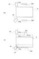
次に、図3及び図4を参照しながら、針無綴じ装置50の構成を説明する。ここで、図4は、針無綴じ装置50の構成及び針無綴じ処理が施された部分を説明するための図であり、図4(a)は針無綴じ装置50の構成を説明するための図であり、図4(b)は用紙Sに形成されるスリット521及び舌部522を説明するための図であり、図4(c)はスリット521へ舌部522を挿入する動作を説明するための図であり、図4(d)は針無綴じ装置50によって綴じ処理を施された部分を説明するための図である。
<
Next, the configuration of the stapleless
まず、第2の綴じ手段の一例である針無綴じ装置50は、ステープル針41を用いることなく、コンパイル用積載部35に収容された用紙Sの束の端部を綴じるよう構成されている(後述)。さらに、針無綴じ装置50は、コンパイル用積載部35の側方であって、第2タンパ38bが設けられている側(図3における上側)に設けられている。さらに本実施の形態においては、ステープラ40は、コンパイル用積載部35における第1タンパ38aが設けられている側でかつエンドガイド35bが設けられている側に近接する部分に設けられている。
ここで、本実施の形態では、ステープラ40をユーザ側(図3における下側)でありかつエンドガイド35b側(図3における左側)に配置し、かつ針無綴じ装置50をステープラ40と対向する側(図3における上側)でありかつエンドガイド35b側(図3における左側)に配置している。この理由は、作業性に関する点と装置の大きさに関する点とがある。
まず、作業性に関する点について説明する。ステープラ40と針無綴じ装置50とを比較すると、ステープラ40は、ある一定の期間経過後にステープル針41の補充が必要なのに対して、針無綴じ装置50は、上述のようにステープル針41を用いないため、ステープル針41の補充が必要ない。つまり、ステープラ40及び針無綴じ装置50に対する保守作業の頻度としては、ステープラ40に対する作業の頻度の方がより高い。よって、ステープラ40に対する作業をより容易に行うことが好ましい。
次に、装置の大きさに関する点について説明する。また、針無綴じ装置50とステープラ40とをコンパイル用積載部35に対して同一の側に配置すると、それぞれの装置自体の大きさのため互いに干渉せずに近接して配置することが難しい。
以上のことから、本実施の形態では、ステープラ40及びかつ針無綴じ装置50を上述のように配置している。
First, the stapleless
Here, in the present embodiment, the
First, the point regarding workability will be described. Comparing the
Next, the point regarding the size of the apparatus will be described. Further, when the stapleless
From the above, in the present embodiment, the
次に、図4を用いて針無綴じ装置50の構造をより詳細に説明する。
この針無綴じ装置50は、対向して配置された基台501と基部503とを有する。そして、図4(a)に示すように基台501に用紙Sの束を挟んだ状態で、基部503を基台501に近接(図中F1方向)することにより、用紙Sの束を綴じるよう構成されている。
Next, the structure of the stapleless
The stapleless
まず、基台501について説明する。基台501には、基台501との間に用紙Sを挟むことができるよう、基台501略平行となるよう配置されている底部材502が設けられている。また、基台501は、基部503に向けて延伸し、基台501と一体的に形成された突出部506を有する。
First, the
次に、基部503について説明する。この基部503は、用紙Sの束に切り込みを入れるブレード504と、用紙Sの束に舌部522(後述)を形成し折り曲げ、かつブレード504によって形成された切り込みに舌部522を挿入する打ち抜き部材505とを有する。
Next, the
この切込部の一例であるブレード504は、基台501と底部材502の間に挟まれた用紙Sの束に向けて延伸する略長方形の板状部材からなる。具体的には、ブレード504は、略長方形状の面に目穴504aを有し、さらに用紙Sに近接するに従いその幅が減少する先端部504bを有する。
The
次に、舌部形成部および切込挿入部の一例である打ち抜き部材505はL字状の屈曲部を有する部材である。そして、打ち抜き部材505の一方の端部は主部505aであり、他方の端部が副部505bである。
また、打ち抜き部材505は、L字状の屈曲部に設けられた主部回転軸505rを有する。そして、この打ち抜き部材505は、主部回転軸505rを中心に回転可能である。より詳細には、主部505aがブレード504側に傾斜可能である。なお、副部505bと基部503との間には、打ち抜き部材505が回転できるよう間隙を有する。
ここで、主部505aは基台501に向けて延伸する。さらに、主部505aは、主部回転軸505rが設けられた側とは反対側、すなわち基台501に対向する側に刃部505cを有する。この刃部505cは、舌部522の形状を打ち抜く刃からなる。なお、刃部505cは、ブレード504と対向する側には刃が形成されておらず、後述する一端部522aによって舌部522と用紙Sが連続するように構成されている。さらに、主部505aは、主部505aの側部、具体的にはブレード504と対向する側に、ブレード504へ向けて延伸する突起505dとを有する。
Next, the punching
The punching
Here, the
さて、針無綴じ装置50によって綴じ処理を行う動作は、次のようになる。
すなわち、図示しない針無綴じモータが駆動され、基部503が基台501に近接し、ブレード504の先端部504bと、打ち抜き部材505の刃部505cとが用紙Sの束を貫通する。そして、貫通された用紙Sの束には、図4(b)に示すように、用紙Sの束にスリット521と、一端部522aを残して用紙Sの束が打ち抜かれた舌部522とがそれぞれ形成される。
そして基部503を更に押下すると、打ち抜き部材505の副部505bが、基台501に一体に形成された突出部506に突き当たり、打ち抜き部材505が、主部回転軸505rを中心に、図4(a)において時計周りに回転する。これにより、主部505aがブレード504側に傾斜し、打ち抜き部材505の突起505dがブレード504に近接する。そして、打ち抜き部材505の突起505dが、図4(c)に示すように、舌部522を折り曲げ、ブレード504の目穴504aに向けて図中F2方向に押し込む。尚、図4(c)では打ち抜き部材505を図示していない。
この状態で、基部503が基台501から離隔させる。つまり、基部503を図中F3方向に上昇させると、舌部522がブレード504の目穴504aに引っ掛けたまま上昇する。そして図4(d)に示すように、スリット521に舌部522が挿入されることにより、用紙Sの束が綴じられる。このとき用紙Sの束には、舌部522が打ち抜かれた箇所に綴じ穴523が形成される。
Now, the operation of performing the binding process by the stapleless
That is, a needleless binding motor (not shown) is driven, the
When the
In this state, the
<画像形成システム1の動作>
次に、図1〜図5を参照して画像形成システム1の動作について説明する。なお、図5は、針無綴じ装置50により綴じられた用紙Sの束の動きを説明するための図である。詳細には、図5(a)は、用紙Sの束がコンパイル用積載部35から搬送される際の動きを説明するための図である。また、図5(b)は、用紙Sの束が第2スタッカ71へと排出される際の動きを説明するための図である。
なお、ここで説明する画像形成システム1は、一つの用紙Sの束に対して、ステープラ40あるいは針無綴じ装置50のいずれか一方のみを用いて綴じ処理を行う。
<Operation of
Next, the operation of the
Note that the
まず、画像形成装置2の画像形成部5によって1番目の用紙Sにトナー像が形成される前の状態は次のように各部材が配置される。すなわち、第1イジェクトロール39aは位置P1に、パドル37は位置Paに配置され、第1タンパ38aは位置Payに配置され、そして第2タンパ38bは位置Pbxに配置される。
First, in the state before the toner image is formed on the first sheet S by the
そして、画像形成装置2の画像形成部5によって1番目の用紙Sにトナー像が形成される。図1に示すように、トナー像が形成された1番目の用紙Sは、必要に応じて用紙反転装置7によって反転された後、排出ロール9を介して、1枚ごとに用紙処理装置3に供給される。
1番目の用紙Sが供給された用紙処理装置3の搬送装置10では、入口ロール11にて1番目の用紙Sを受け取り、この1番目の用紙Sについて、必要に応じてパンチャ12により穴あけ処理が施される。その後、第1搬送ロール13および第2搬送ロール14を介して、1番目の用紙Sが下流側の後処理装置30に向けて搬送される。
Then, a toner image is formed on the first sheet S by the
In the
後処理装置30では、受け取りロール31により1番目の用紙Sを受け取る。受け取りロール31を経た1番目の用紙Sは、エグジットロール34によって第1の進行方向S1に沿って搬送される。このとき、1番目の用紙Sはコンパイル用積載部35と第1イジェクトロール39aとの間、およびコンパイル用積載部35とパドル37との間をそれぞれ通過するように搬送される。
1番目の用紙Sの第1の進行方向S1の先端が、コンパイル用積載部35とパドル37との間を通過した後、パドル37が位置Paから下降(図2の矢印U1方向に移動)し位置Pbに配置される。このことによりパドル37は、1番目の用紙Sと接触する。そして、1番目の用紙Sは、図2に示すパドル37の矢印R方向の回転により、図2の第2の進行方向S2方向に押し込まれ、その1番目の用紙Sのエンドガイド35b側の端部がエンドガイド35bと接触する。その後、パドル37は上昇(図2の矢印U2方向に移動)し1番目の用紙S1から離れ、位置Paに再び配置される。
さらに、1番目の用紙Sがコンパイル用積載部35に受け入れられ、エンドガイド35b側の端部がエンドガイド35bに到達した後に、第1タンパ38aが、位置Payからコンパイル用積載部35に接近(図3の矢印C2方向に移動)して、位置Paxに配置される。このとき、第2タンパ38bは、位置Pbxに配置されたままである。このことにより、第1タンパ38aが1番目の用紙Sを押し、1番目の用紙Sが第2タンパ38bに接触する。その後、第1タンパ38aがコンパイル用積載部35から離間(図3の矢印C1方向に移動)することで1番目の用紙Sから離れ、位置Payに再び配置される。
In the
After the leading edge of the first sheet S in the first advancing direction S1 passes between the compiling stacking
Further, after the first sheet S is received by the
この1番目の用紙Sに続く、画像形成部5によってトナー像が形成された2番目以降の用紙Sが、それぞれ順に後処理装置30に供給された際も、上述の動作と同様に、パドル37およびタンパ38によって、用紙Sの端部が揃えられる。すなわち、1枚目の用紙Sが揃えられた状態で2枚目の用紙Sが供給され、1枚目の用紙Sに対して2枚目の用紙Sが揃えられる。このことは、3枚目の以降に用紙Sが供給される場合についても同様である。このようにすることで、予め設定された枚数の用紙Sをコンパイル用積載部35に収容し、各用紙Sの端部を揃えて、用紙Sの束を形成する。
そして、第1イジェクトロール39aは位置P1から下降(図2の矢印Q1方向に移動)し、位置P2に配置される。このことにより、揃えられた状態の用紙Sの束は、第1イジェクトロール39aと第2イジェクトロール39bとによって挟まれて固定される。
When the second and subsequent sheets S on which the toner image is formed by the
Then, the
次に、ステープラ40あるいは針無綴じ装置50のいずれか一方によって、コンパイル用積載部35に積載された用紙Sの束の端部を綴じる。
Next, the end of the bundle of sheets S stacked on the
ステープラ40あるいは針無綴じ装置50のいずれか一方によって綴じられた用紙Sの束は、第1イジェクトロール39aが順方向(図2の矢印T1)あるいは逆方向(図2の矢印T2)方向に回転することにより、コンパイル用積載部35から排出される。
ここで、用紙Sの束がこのコンパイル用積載部35から排出される排出用搬送経路には、第1の排出用搬送経路及び第2の排出用搬送経路がある。第1の排出用搬送経路においては、用紙Sの束は第1開口部69を通って、第1スタッカ70へと排出される。一方、第2の排出用搬送経路においては、用紙Sの束は反転搬送ロール73を経て、第2開口部72を通って、第2スタッカ71へと排出される。つまり、第1の排出用搬送経路及び第2の排出用搬送経路をそれぞれ搬送される用紙Sの束は、コンパイル用積載部35から排出される際には逆方向に進む。
そして、第1の排出用搬送経路はステープラ40によって綴じられた用紙Sの束が搬送される。一方、第2の排出用搬送経路は、針無綴じ装置50によって綴じられた用紙Sの束が搬送される。
In the bundle of sheets S bound by either the
Here, the discharge transport path from which the bundle of sheets S is discharged from the
Then, a bundle of sheets S bound by the
再び用紙Sの束がコンパイル用積載部35から排出される動作についての説明に戻る。ここではまず、第1の排出用搬送経路を経て用紙Sの束が排出される場合を説明した後に、第2の排出用搬送経路を経て用紙Sの束が排出される場合を説明する。
The description returns to the operation for discharging the bundle of sheets S from the
第1の排出用搬送経路を経て用紙Sの束が排出される場合、第1イジェクトロール39aが図2に示す矢印T1方向に回転することにより、用紙Sの束がコンパイル用積載部35から排出される(図2の第3の進行方向S3)。そして、排出された用紙Sの束は第1開口部69を通って、第1スタッカ70へと排出される。
When a bundle of sheets S is discharged through the first discharge conveyance path, the
一方、第2の排出用搬送経路を経て用紙Sの束が排出される場合、エンドガイド35bは回転軸35cを中心に回転する。これにより、エンドガイド35bは、第2の排出用搬送経路へ向かう方向(図2の第2の進行方向S2参照)へ用紙Sの束が移動するのを妨げない位置に移動する。
さらに、第1イジェクトロール39aが図2に示す矢印T2方向に回転することにより、用紙Sの束がコンパイル用積載部35から排出される(図2の第2の進行方向S2参照)。
そして、排出された用紙Sの束は、反転搬送ロール73によって上面側と下面側とを反転させて搬送する。反転搬送された用紙Sの束は、第2開口部72を通って、第2スタッカ71へと排出される。
On the other hand, when the bundle of sheets S is discharged through the second discharge conveyance path, the
Further, when the
Then, the bundle of discharged sheets S is transported by reversing the upper surface side and the lower surface side by the
上述のように、ステープラ40によって綴じられた用紙Sの束と針無綴じ装置50によって綴じられた用紙Sの束とが、それぞれ第1の排出用搬送経路あるいは第2の排出用搬送経路という異なる経路によって搬送されることにより、針無綴じ装置50によって綴じられた部分が受ける損傷を低減できるという利点がある。この利点について以下で詳細に説明する。
As described above, the bundle of sheets S bound by the
まず、針無綴じ装置50によって綴じられた部分は、用紙Sの束の厚み方向において用紙Sの面よりも突出する部分を有する。例えば、舌部522の端部は、用紙Sの面よりも突出する(図4(d)参照)。なお、例えば図4(d)では確認できないが、用紙Sの裏面側においても、舌部522の折り返された部分が、用紙Sの裏面側の面から突出する。
そして、用紙Sの面よりも突出した部分が存在する場合、連続して用紙Sの束が綴じられるときに、用紙Sの面よりも突出した部分は損傷を受けやすい。
First, the portion bound by the stapleless
If there is a portion protruding from the surface of the paper S, the portion protruding from the surface of the paper S is easily damaged when a bundle of the paper S is continuously bound.
ここで、突出した部分が受ける損傷について、説明する。ここでは、例として、第1開口部69から排出され第1スタッカ70に積載される用紙Sの束を基準とし、この用紙Sの束(以下、基準用紙束)と、この基準用紙束の直前に第1スタッカ70に積載された用紙Sの束(以下、先行用紙束)を考え、これらについて説明する。
まず、基準用紙束と先行用紙束を、それぞれ搬送して同一のスタッカに積載する場合、基準用紙束は先行用紙束と接触し、先行用紙束の面を滑りながら搬送される。そして、この基準用紙束と先行用紙束とが接触しながら搬送される際に、基準用紙束と先行用紙束とが対向する面に突出した部分があると、この突出した部分は損傷を受けやすい。損傷は、例えば基準用紙束の搬送方向先端側の端部が、先行用紙束の上面側に形成された突出した部分と、衝突あるいは引っかかることにより生じる。
Here, the damage which the protrusion part receives is demonstrated. Here, as an example, a bundle of sheets S discharged from the
First, when the reference sheet bundle and the preceding sheet bundle are respectively transported and stacked on the same stacker, the reference sheet bundle comes into contact with the preceding sheet bundle and is conveyed while sliding on the surface of the preceding sheet bundle. When the reference sheet bundle and the preceding sheet bundle are conveyed while being in contact with each other, if there is a protruding part on the surface where the reference sheet bundle and the preceding sheet bundle face each other, the protruding part is easily damaged. . The damage occurs, for example, when the end of the reference sheet bundle in the conveyance direction on the leading end side collides with or gets caught by a protruding portion formed on the upper surface side of the preceding sheet bundle.
次に、針無綴じ装置50は、用紙Sの一部を加工して綴じ処理を施すことから、例えば2枚乃至10枚程度の枚数の用紙Sの束を綴じる。一方のステープラ40は、金属製のステープラを用いて綴じ処理を施すことから、例えば100枚程度の枚数の用紙Sの束を綴じることも可能である。したがって、ステープラ40によって綴じられた用紙Sの束は、針無綴じ装置50によって綴じられた用紙Sの束よりも重量が非常に大きい場合がある。
したがって、特に先行用紙束が針無綴じ装置50によって綴じられ、基準用紙束がステープラ40によって綴じられる場合、基準用紙束の重さのために、先行用紙束の突出した部分はより損傷を受けやすい
Next, since the stapleless
Therefore, particularly when the preceding sheet bundle is bound by the stapleless
そこで、用紙Sの面よりも突出した部分が損傷を受けることを回避するには、この用紙Sの面よりも突出した部分すなわち、針無綴じ装置50によって綴じ処理が施された部分が通過する領域が、ステープラ40によって綴じられた用紙Sの束が通過する領域とは異なることが好ましい。
そして、上述のようにステープラ40及び針無綴じ装置50それぞれによって綴じられた用紙Sの束が異なる経路によって搬送されると、針無綴じ装置50によって綴じ処理が施された部分は、ステープラ40によって綴じられた用紙Sの束とは異なる領域を通過する。従って、針無綴じ装置50によって綴じられた部分が受ける損傷を抑制できる。
Therefore, in order to avoid damage to the portion protruding from the surface of the sheet S, the portion protruding from the surface of the sheet S, that is, the portion subjected to the binding process by the stapleless
When the bundle of sheets S bound by the
なお、上述のように基準用紙束の搬送方向先端側の端部が、先行用紙束の上面側に形成された突出した部分と、衝突あるいは引っかかることにより、損傷が生じることがある。従って、例えば、第2スタッカ71へと積載される際に、用紙Sの面よりも突出した部分が用紙Sの束の下面側となるように排出されることが好ましい。このことにより、先行用紙束の突出した部分が、基準用紙束の搬送方向先端側の端部によって損傷を受けることが回避できる。
As described above, the end of the reference sheet bundle in the conveyance direction may collide with or protrude from the protruding portion formed on the upper surface side of the preceding sheet bundle, and damage may occur. Therefore, for example, when being stacked on the
<他の実施の形態>
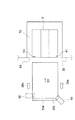
次に、図6乃至図8を参照しながら、綴じ処理が施された部分をずらして排出する構成を用いた他の実施の形態における動作について説明する。
ここで、図6は、針無綴じ装置50により綴じ処理が施される用紙Sの動きを説明するための図である。同図は、図2におけるIII方向から見たコンパイル用積載部35周辺を示す。なお、図6においては、コンパイル用積載部35は省略している。図6を詳細に説明すると、図6(a)は、針無綴じ装置50によって綴じ処理を施す際に供給された用紙Sとタンパ38との位置関係を示す図である。そして図6(b)は、針無綴じ装置50によって綴じ処理が施された用紙Sの位置を示す図である。
また、図7は、ステープラ40により綴じ処理が施される用紙Sの動きを説明するための図である。詳細に説明すると、図7(a)は、ステープラ40によって綴じ処理を施す際に供給された用紙Sとタンパ38との位置関係を示す図である。そして図7(b)は、ステープラ40によって綴じ処理が施された用紙Sの位置を示す図である。
さらに、図8は、ステープラ40および針無綴じ装置50それぞれによって綴じ処理が施された用紙Sの束が第1開口部69を通って、第1スタッカ70へと排出された際の位置を説明するための図である。
<Other embodiments>
Next, with reference to FIGS. 6 to 8, an operation in another embodiment using a configuration in which a portion subjected to the binding process is shifted and discharged will be described.
Here, FIG. 6 is a diagram for explaining the movement of the sheet S on which the binding process is performed by the stapleless
FIG. 7 is a diagram for explaining the movement of the sheet S on which the binding process is performed by the
Further, FIG. 8 illustrates a position when the bundle of sheets S subjected to the binding process by the
ここで、上述の図3に示す実施の形態と、図6乃至図8に示す実施の形態との違いは、次のようになる。
まず、図3に示す実施形態においては、針無綴じ装置50によって綴じ処理が施される場合及びステープラ40によって綴じ処理が施される場合のいずれであっても、綴じ処理がなされる用紙Sの束は同一の位置に配置される。つまり、コンパイル用積載部35の底部35aにおける同じ位置で、用紙Sの束に綴じ処理が施される。
Here, the difference between the embodiment shown in FIG. 3 and the embodiment shown in FIGS. 6 to 8 is as follows.
First, in the embodiment shown in FIG. 3, the sheet S to which the binding process is performed is performed regardless of whether the binding process is performed by the stapleless
これに対して、図6等に示す実施形態においては、針無綴じ装置50によって綴じ処理が施される場合と、ステープラ40によって綴じ処理が施される場合とで、コンパイル用積載部35の底部35aにおける用紙Sの束の位置が異なる。具体的には、排出用搬送経路と交差する方向(図8の上下方向)における位置が異なる。より具体的には、ステープラ40によって綴じられた用紙Sの束よりも、針無綴じ装置50によって綴じられた用紙Sの束の方が図8における上側(より第2タンパ38bに近い側)に配置される。
なお、予め定めた箇所に綴じ処理を施すことが可能とするため、図6乃至図8におけるステープラ40と針無綴じ装置50との間隔は、図3におけるステープラ40と針無綴じ装置50との間隔よりも長い。また、図6乃至図8におけるステープラ40と針無綴じ装置50との間隔は、綴じられる用紙Sの長さ(図8の上下方向の長さ)よりも長くなるよう配置されている。
On the other hand, in the embodiment shown in FIG. 6 and the like, the bottom portion of the compile stacking
In addition, in order to perform a binding process to a predetermined location, the interval between the
また、上述の実施の形態においては、排出用搬送経路には、ステープラ40によって綴じられた用紙Sの束は第1の排出用搬送経路へ搬送され、針無綴じ装置50によって綴じられた用紙Sの束は第2の排出用搬送経路へ搬送された。
しかしながら、図6に示す実施形態においては、ステープラ40及び針無綴じ装置50によって綴じられた用紙Sの束はいずれも同一の排出用搬送経路へ搬送される。ここでは、用紙Sの束は第1の排出用搬送経路へ搬送される。
In the above-described embodiment, the bundle of sheets S bound by the
However, in the embodiment shown in FIG. 6, all the bundles of sheets S bound by the
以下で、図6乃至図8を参照しながら、用紙Sの束の位置が異なる点について詳細に説明する。
まず、図6を用いて針無綴じ装置50によって綴じ処理を施す際のタンパ38と用紙Sの配置を説明する。図6(a)に示すように、用紙Sがコンパイル用積載部35に供給されるとき、第1タンパ38a及び第2タンパ38bは、それぞれコンパイル用積載部35の底部35a(図3参照)から離隔された側に配置されている。具体的には、第1タンパ38a及び第2タンパ38bは、それぞれ位置Pay、Pbyに配置されている。そして、コンパイル用積載部35の底部35aから離隔された側に配置されている第1タンパ38a及び第2タンパ38bの間に、用紙Sが供給される。
そして、図6(b)に示すように、第1タンパ38aと第2タンパ38bとの間に、用紙Sが存在する状態(図6(b)の破線で示された用紙S参照)で、第1タンパ38aが第2タンパ38bに接近する(図6(b)の矢印C2参照)。具体的には、第1タンパ38aは、位置Payから位置Paxに移動する。この第1タンパ38aの移動により、用紙Sは第2タンパ38b側に移動し、位置Pbyに配置された第2タンパ38bに接するよう配置される(図6(b)の実線で示された用紙S参照)。
Hereinafter, the difference in the position of the bundle of sheets S will be described in detail with reference to FIGS. 6 to 8.
First, the arrangement of the
Then, as shown in FIG. 6B, in a state where the sheet S exists between the
この用紙Sに続く、2番目以降の用紙Sが、それぞれ順に後処理装置30に供給された際も、上述の動作と同様に、タンパ38によって位置Pbyに配置された第2タンパ38bに接するよう配置され、用紙Sの端部が揃えられる。
そして、用紙Sは、第2タンパ38bに接する位置において、針無綴じ装置50により綴じ処理が施される。本実施の形態においては、針無綴じ装置50によって綴じ処理が施された部分である針無綴じ部分51は、図6における用紙Sの上側端部(第2タンパ38bに近い側の端部)に配置される。綴じ処理が施された用紙Sの束は、イジェクトロール39によって、第1の排出用搬送経路(図6における右側)へと排出され、第1スタッカ70に配置される。
When the second and subsequent sheets S following this sheet S are sequentially supplied to the
The sheet S is subjected to a binding process by the stapleless
次に、図7を用いてステープラ40によって綴じ処理を施す際のタンパ38と用紙Sの配置を説明する。図7(a)に示すように、用紙Sがコンパイル用積載部35に供給されるとき、上述の図6(a)の状態と同様の配置となる。すなわち、第1タンパ38a及び第2タンパ38bは、それぞれコンパイル用積載部35の底部35a(図3参照)から離隔された側である位置Pay、Pbyに配置されている。そして、コンパイル用積載部35の底部35a(図3参照)から離隔された側に配置されている第1タンパ38a及び第2タンパ38bの間に、用紙Sが供給される。
次の図7(b)に示す動きは、上述の図6(a)に示す動きと異なる。すなわち、図7(b)に示すように、第1タンパ38aと第2タンパ38bとの間に、用紙Sが存在する状態(図7(b)の破線で示された用紙S参照)で、第2タンパ38bが、第1タンパ38aに近接する(図7(b)の矢印C3参照)。具体的には、第2タンパ38bは、位置Pbyから位置Pbxに移動する。この第2タンパ38bの移動により、用紙Sは第1タンパ38a側に移動し、位置Payに配置された第1タンパ38aに接するよう配置される(図7(b)の実線で示された用紙S参照)。
Next, the arrangement of the
The movement shown in FIG. 7B is different from the movement shown in FIG. That is, as shown in FIG. 7B, in a state where the paper S exists between the
この用紙Sに続く、2番目以降の用紙Sが、それぞれ順に後処理装置30に供給された際も、上述の動作と同様に、タンパ38によって位置Payに配置された第1タンパ38aに接するよう配置され、用紙Sの端部が揃えられる。
そして、用紙Sは、第1タンパ38aに接する位置において、ステープラ40により綴じ処理が施される。本実施の形態においては、ステープラ40によって綴じ処理が施された部分であるステープル針41は、図6における用紙Sの下側端部(第1タンパ38aに近い側)に配置される。綴じ処理が施された用紙Sの束は、イジェクトロール39によって、第1の排出用搬送経路(図7における右側)へと排出され第1スタッカ70に配置される。
When the second and subsequent sheets S following this sheet S are sequentially supplied to the
The sheet S is then subjected to a binding process by the
以上のことより、本実施の形態においては、針無綴じ装置50によって綴じ処理が施される場合と、ステープラ40によって綴じ処理が施される場合とで、コンパイル用積載部35の底部35aにおける用紙Sの束の位置が異なる。具体的には、用紙Sの束が搬送される方向(図8の矢印S3参照)と交差する方向において、互いに異なる位置にそれぞれの用紙Sの束が配置される。
そして、ステープル針41と針無綴じ部分51とは、搬送の過程においても用紙Sの束の搬送方向と交差する方向において異なる位置を維持し、ステープル針41が通る領域と針無綴じ部分51が通る領域とは重複しない。
さらに、図8に示すように、第1スタッカ70上に用紙Sの束が配置された状態においても、用紙Sの束を綴じたステープル針41の位置と、用紙Sの束を綴じた針無綴じ部分51の位置とは互いに重複しない。
従って、針無綴じ装置50によって綴じられた部分である針無綴じ部分51が搬送にともなって受ける損傷を低減できる。
As described above, in the present embodiment, the sheet in the
The
Further, as shown in FIG. 8, even when the bundle of sheets S is arranged on the
Therefore, it is possible to reduce the damage that the
なお、ここでは用紙Sが一枚供給されるごとにタンパ38を動かし、それぞれの位置において綴じ処理を施すことを説明したが、これに限定されない。例えば、用紙Sがコンパイル用積載部35に供給された位置から用紙Sを動かすことなく、用紙Sの束を形成する。そして、用紙Sが供給された位置において、針無綴じ装置50あるいはステープラ40によって綴じ処理が施され綴じ処理を施した後、それぞれの位置に移動させる構成であってもよい。つまり、用紙Sを一枚ずつではなく、用紙Sの束に綴じ処理を施した後に、用紙Sの束が搬送される方向(図2の矢印S3参照)と交差する方向において、互いに異なる位置にそれぞれの用紙Sの束が配置されてもよい。
Here, it has been described that the
また、ここでは用紙Sの束を揃えるタンパ38が、針無綴じ装置50によって綴じられる用紙Sの束あるいはステープラ40によって綴じられる用紙Sの束の位置を異ならせることを説明したが、これに限定されない。例えば、タンパ38とは別部材により、用紙Sの束を移動させる構成であってもよい。
さらに、ここではコンパイル用積載部35上で用紙Sの束の位置を異ならせることを説明したが、これに限定されない。例えば、第1開口部69から第1スタッカ70上に排出される際に、配置機構が用紙Sの束を移動させる構成であってもよい。この配置機構は、例えば第1開口部69に設けられる。そして、配置機構は、用紙Sの束が第1開口部69を通過する際に、針無綴じ装置50あるいはステープラ40のいずれによって綴じられたかに応じて、用紙Sの束が搬送される方向(図8の矢印S3参照)と交差する方向に用紙Sの束を移動させる。
Further, here, it has been described that the
Further, here, it has been described that the position of the bundle of sheets S on the
さて、上述の実施形態においては、針無綴じ装置50が舌部522及びスリット521によって綴じる構成を説明したが、これに限定されない。
ここで、図9を参照しながら針無綴じ装置50は別の形態であってもよいことを説明する。なお、図9は、他の実施の形態により針無綴じ処理が施された用紙の束を説明するための図であり、図9(a)は、矢印形の形状の切り込みを作成することにより綴じ処理を行う例を示し、図9(b)は、エンボス跡を作成することにより綴じ処理を行う例を示す。
まず、図9(a)に示す綴じの態様では、用紙Sの束の一部に矢印形511を形成する。この矢印形511は、柄側の端部が用紙Sと連続するよう残して打ち抜かれている。そして、この矢印形511を立ち上げ、立ち上げた矢印形511と抜き穴との摩擦によって用紙Sの束を保持するものである。
一方、図9(b)に示す綴じの態様では、用紙Sの束の一部に、エンボス跡512を形成することによって用紙S束を綴じる。すなわち図9(b)に示す用紙Sの束における図中上側の面から、この用紙Sの束の反対側の面に向けてエンボス跡512を形成する部材を押し当てることにより、図9(b)に示す用紙Sの束の観察できる側の面に凹部を形成する(反対側の面には凸部が形成される)ことにより、綴じ処置を施す。
In the above-described embodiment, the configuration in which the stapleless
Here, it will be described with reference to FIG. 9 that the needleless
First, in the binding mode shown in FIG. 9A, an
On the other hand, in the binding mode illustrated in FIG. 9B, the sheet S bundle is bound by forming an
なお、図9(a)及び(b)いずれに示す綴じの態様であっても、原則として、少なくとも一方の側には用紙Sの面よりも突出した部分を有する。従って、上述の実施の形態と同様に、連続して用紙Sの束が綴じられるときに、用紙Sの面よりも突出した部分は損傷を受けやすい。 9A and 9B, in principle, at least one side has a portion protruding from the surface of the sheet S, regardless of the binding mode shown in FIGS. Therefore, similarly to the above-described embodiment, when a bundle of sheets S is continuously bound, a portion protruding from the surface of the sheet S is easily damaged.
また、上述の実施の形態においては、ステープラ40及び針無綴じ装置50の位置を移動させないものとして説明したが、これに限定されない。たとえば、ステープラ40及び針無綴じ装置50をそれぞれコンパイル用積載部35の周囲に設けられたレール上に備えることなどによって移動可能に設けてもよい。テープラ40及び針無綴じ装置50のそれぞれを移動可能とすることにより、用紙Sにおける綴じ処理を施す位置や、用紙Sの用紙サイズや向きに応じて綴じ処理を施す位置を変化させることができる。
In the above-described embodiment, the positions of the
さらに、上述の通り、画像形成システム1は、一つの用紙Sの束に対して、ステープラ40あるいは針無綴じ装置50のいずれか一方のみを用いて綴じ処理を行うが、ステープラ40あるいは針無綴じ装置50のいずれを用いるかは、任意に選択可能である。
一方で、用紙Sの束における用紙Sの枚数、用紙Sの種類(厚紙、薄紙、コーティング紙等)、及び用紙Sの束の厚さに応じて、制御部80がステープラ40あるいは針無綴じ装置50のいずれかを選択するようにしてもよい。例えば、あらかじめ定められた枚数以下の枚数を綴じる場合には、針無綴じ装置50を用いて綴じ処理を行い、あらかじめ定められた枚数よりも多い枚数を綴じる場合には、ステープラ40を用いて綴じ処理を行う。
また、一方の綴じ手段によって綴じるよう、制御部80が指示を受けた場合であっても、その指示において選択された綴じ手段によって綴じることが適切でない場合は、制御部80が他方の綴じ手段によって綴じるよう切り替えるか、あるいはユーザ・インターフェイス90を介して適切な指示でないことを報知してもよい。例えば、用紙Sの種類(厚紙、薄紙、コーティング紙等)、及び用紙Sの束の厚さが、指示において選択された綴じ手段によって綴じることが適切か否かを制御部80が判断してもよい。
Further, as described above, the
On the other hand, according to the number of sheets S in the bundle of sheets S, the type of sheets S (thick paper, thin paper, coated paper, etc.), and the thickness of the bundle of sheets S, the
Further, even when the
1…画像形成システム、2…画像形成装置、3…用紙処理装置、10…搬送装置、30…後処理装置、34…エグジットロール、35…コンパイル用積載部、37…パドル、38…タンパ、39…イジェクトロール、40…ステープラ、50…針無綴じ装置、69…第1開口部、70…第1スタッカ、71…第2スタッカ、72…第2開口部、80…制御部
DESCRIPTION OF
Claims (9)
積載手段上の用紙束を夫々第1綴処理により第1用紙束として綴じる第1綴手段及び、第2綴処理により第2用紙束として綴じる第2綴じ手段と、A first binding unit that binds the sheet bundle on the stacking unit as a first sheet bundle by the first binding process; and a second binding unit that binds as a second sheet bundle by the second binding process;
第1用紙束を搬送する際には前記積載手段から第1経路に向けて搬送し、第2用紙束を搬送する際には当該積載手段から当該第1経路とは逆方向の第2経路に向けて搬送する搬送手段とを備えたことを特徴とする用紙処理装置。When transporting the first sheet bundle, it is transported from the stacking means toward the first path, and when transporting the second sheet bundle, the stacking means travels from the stacking means to the second path in the direction opposite to the first path. A sheet processing apparatus comprising a conveying unit that conveys the sheet toward the sheet.
前記積載手段に積載された前記用紙束を第1の綴じ処理により第1の用紙束として綴じる第1の綴じ手段と、
前記積載手段に積載された前記用紙束を第2の綴じ処理により第2の用紙束として綴じる第2の綴じ手段と、
前記第1の用紙束を搬送する際には前記積載手段から第1経路に向けて搬送し、かつ前記第2の用紙束を搬送する際には当該積載手段から当該第1経路とは逆方向の第2経路に向けて搬送する搬送手段と、
前記第2経路に配置され、前記第2の用紙束の上面側と下面側とを反転させて搬送する反転搬送手段と、
前記第1経路に配置され、前記搬送手段によって搬送された前記第1の用紙束を配置させる第1の搬送束積載手段と、
前記第2経路に配置され、前記反転搬送手段によって反転搬送された前記第2の用紙束を配置させる第2の搬送束積載手段と
を備えたことを特徴とする用紙処理装置。 A stacking means for stacking a stack of sheets with the sheets aligned;
A first binding unit that binds the bundle of sheets stacked on the stacking unit as a first bundle of sheets by a first binding process;
A second binding means for binding the sheet bundle loaded on the stacking means as a second sheet bundle by a second binding process;
When transporting the first sheet bundle, it is transported from the stacking means toward the first path, and when transporting the second sheet bundle, the direction opposite to the first path is from the stacking means. Conveying means for conveying toward the second path of
A reversing and conveying means arranged in the second path for conveying the second sheet bundle by reversing the upper surface side and the lower surface side;
A first transport bundle stacking unit disposed on the first path and configured to dispose the first sheet bundle transported by the transport unit;
A sheet processing apparatus, comprising: a second transport bundle stacking unit disposed on the second path and configured to dispose the second sheet bundle reversed and conveyed by the reverse conveyance unit.
前記端部揃え部が、前記第2の用紙束を前記積載手段から前記第2経路に搬送する際に、当該第2の用紙束が搬送されることを妨げない位置に移動することを特徴とする請求項2記載の用紙処理装置。 An edge that prevents the second sheet bundle from being transported from the stacking unit to the second path and is arranged in contact with an end that is the leading end side in the transport direction of the second sheet bundle and aligns the end. It has a part alignment part,
When the second sheet bundle is conveyed from the stacking unit to the second path, the edge aligning unit moves to a position that does not prevent the second sheet bundle from being conveyed. The sheet processing apparatus according to claim 2 .
前記用紙束に切り込みを形成する切込部と、
前記用紙束の一部を特定の形に切ることにより、一方の端部が当該用紙束と連続する部分を残す舌部を当該用紙束に形成する舌部形成部と、
前記舌部を折り当該舌部の他方の端部を前記切り込みに挿入する切込挿入部と
を有することを特徴とする請求項2乃至5のいずれか1項記載の用紙処理装置。 The second binding means includes
A notch for forming a notch in the sheet bundle;
A tongue forming portion for forming a tongue on the sheet bundle, in which a portion of one end portion is continuous with the sheet bundle by cutting a part of the sheet bundle into a specific shape;
Sheet processing apparatus according to any one of claims 2 to 5, characterized in that it has a cutout insertion portion for inserting the other end of the tongue folding the tongues cut the.
用紙に画像を形成して前記用紙処理装置に向けて供給する画像形成装置と
を含むことを特徴とする画像形成システム。 A sheet processing apparatus according to any one of claims 1 to 8 ,
An image forming system comprising: an image forming apparatus that forms an image on a sheet and supplies the image to the sheet processing apparatus.
Priority Applications (3)
| Application Number | Priority Date | Filing Date | Title |
|---|---|---|---|
| JP2010131828A JP5218478B2 (en) | 2010-06-09 | 2010-06-09 | Paper processing apparatus and image forming system |
| US13/035,224 US8444133B2 (en) | 2010-06-09 | 2011-02-25 | Sheet processing apparatus, image forming system, and sheet processing method |
| CN201110086426.XA CN102275763B (en) | 2010-06-09 | 2011-04-07 | Paper processing device, image formation system and paper object processing method |
Applications Claiming Priority (1)
| Application Number | Priority Date | Filing Date | Title |
|---|---|---|---|
| JP2010131828A JP5218478B2 (en) | 2010-06-09 | 2010-06-09 | Paper processing apparatus and image forming system |
Publications (3)
| Publication Number | Publication Date |
|---|---|
| JP2011256009A JP2011256009A (en) | 2011-12-22 |
| JP2011256009A5 JP2011256009A5 (en) | 2012-11-29 |
| JP5218478B2 true JP5218478B2 (en) | 2013-06-26 |
Family
ID=45095603
Family Applications (1)
| Application Number | Title | Priority Date | Filing Date |
|---|---|---|---|
| JP2010131828A Expired - Fee Related JP5218478B2 (en) | 2010-06-09 | 2010-06-09 | Paper processing apparatus and image forming system |
Country Status (3)
| Country | Link |
|---|---|
| US (1) | US8444133B2 (en) |
| JP (1) | JP5218478B2 (en) |
| CN (1) | CN102275763B (en) |
Families Citing this family (43)
| Publication number | Priority date | Publication date | Assignee | Title |
|---|---|---|---|---|
| JP3242760B2 (en) * | 1993-07-22 | 2001-12-25 | 富士写真フイルム株式会社 | Rod for coating equipment |
| JP5533442B2 (en) * | 2010-08-26 | 2014-06-25 | 富士ゼロックス株式会社 | Image forming apparatus |
| JP5896779B2 (en) * | 2012-02-22 | 2016-03-30 | キヤノン株式会社 | Printing apparatus, binding apparatus, control method thereof, and program |
| JP6232704B2 (en) * | 2012-04-16 | 2017-11-22 | 株式会社リコー | Sheet processing apparatus and image forming system |
| JP5904888B2 (en) * | 2012-06-28 | 2016-04-20 | キヤノン株式会社 | Image processing apparatus, information processing apparatus, control method, and program |
| JP6075838B2 (en) * | 2012-09-20 | 2017-02-08 | キヤノン株式会社 | Sheet processing apparatus and image forming apparatus |
| JP6537585B2 (en) * | 2012-09-20 | 2019-07-03 | キヤノン株式会社 | Sheet processing apparatus and image forming apparatus |
| JP6261233B2 (en) * | 2012-09-20 | 2018-01-17 | キヤノン株式会社 | Sheet processing apparatus and image forming apparatus |
| JP6102218B2 (en) * | 2012-11-27 | 2017-03-29 | 株式会社リコー | Image forming system |
| JP6403449B2 (en) | 2013-07-01 | 2018-10-10 | キヤノン株式会社 | Sheet processing apparatus and image forming apparatus |
| JP6198490B2 (en) * | 2013-07-05 | 2017-09-20 | キヤノン株式会社 | Sheet processing apparatus and image forming apparatus |
| JP6360284B2 (en) * | 2013-07-11 | 2018-07-18 | キヤノンファインテックニスカ株式会社 | Sheet processing apparatus and image forming system provided with the same |
| JP6141128B2 (en) * | 2013-07-11 | 2017-06-07 | キヤノンファインテック株式会社 | Sheet bundle binding processing apparatus and image forming system using the same |
| JP6334860B2 (en) * | 2013-07-11 | 2018-05-30 | キヤノンファインテックニスカ株式会社 | Sheet bundle binding processing apparatus and image forming system provided with the same |
| JP6360285B2 (en) * | 2013-07-12 | 2018-07-18 | キヤノンファインテックニスカ株式会社 | Sheet processing apparatus and image forming system provided with the same |
| JP6164960B2 (en) * | 2013-07-16 | 2017-07-19 | キヤノン株式会社 | Sheet processing apparatus and image forming apparatus |
| JP6282416B2 (en) * | 2013-07-17 | 2018-02-21 | キヤノンファインテックニスカ株式会社 | Sheet processing device |
| US9394136B2 (en) * | 2013-07-17 | 2016-07-19 | Canon Finetech Inc. | Sheet bundle binding processing apparatus and image forming system having the same |
| JP6274768B2 (en) * | 2013-07-18 | 2018-02-07 | キヤノンファインテックニスカ株式会社 | Sheet bundle binding processing apparatus and image forming system provided with the same |
| JP6238614B2 (en) | 2013-07-22 | 2017-11-29 | キヤノン株式会社 | Sheet processing apparatus and image forming apparatus |
| JP6032556B2 (en) * | 2013-08-02 | 2016-11-30 | 株式会社リコー | Paper processing apparatus and image forming system |
| JP6235900B2 (en) * | 2013-12-27 | 2017-11-22 | キヤノンファインテックニスカ株式会社 | Sheet binding processing apparatus and image forming system using the same |
| JP6582541B2 (en) * | 2014-06-16 | 2019-10-02 | 株式会社リコー | Sheet processing apparatus and image forming system |
| JP2016003118A (en) * | 2014-06-18 | 2016-01-12 | ニスカ株式会社 | Sheet binding processing apparatus and post-processing apparatus including the same |
| KR20160026255A (en) | 2014-08-29 | 2016-03-09 | 삼성전자주식회사 | Finishing apparatus and image forming apparatus having same |
| JP6425536B2 (en) | 2014-12-25 | 2018-11-21 | キヤノン株式会社 | Image forming apparatus, control method of image forming apparatus, and program |
| JP6465649B2 (en) * | 2014-12-25 | 2019-02-06 | キヤノン株式会社 | Image forming apparatus, image forming apparatus control method and program |
| JP6391472B2 (en) * | 2015-01-07 | 2018-09-19 | キヤノン株式会社 | Image processing apparatus, image processing apparatus control method, and program |
| JP6455972B2 (en) * | 2015-02-16 | 2019-01-23 | 株式会社デュプロ | Paper binding device |
| US9713933B2 (en) * | 2015-04-15 | 2017-07-25 | Kabushiki Kaisha Toshiba | Sheet post-processing apparatus |
| US10012939B2 (en) * | 2015-11-06 | 2018-07-03 | Ricoh Company, Ltd. | Image forming apparatus and program product used in the image forming apparatus |
| US20170285550A1 (en) * | 2016-03-29 | 2017-10-05 | Fuji Xerox Co., Ltd. | Image forming system |
| JP6142939B1 (en) * | 2016-03-29 | 2017-06-07 | 富士ゼロックス株式会社 | Image forming system |
| JP6415644B2 (en) * | 2017-06-19 | 2018-10-31 | キヤノン株式会社 | Sheet processing apparatus and image forming apparatus |
| JP6412628B2 (en) * | 2017-10-27 | 2018-10-24 | キヤノンファインテックニスカ株式会社 | Sheet processing apparatus and image forming system using the same |
| US11084244B2 (en) * | 2018-02-15 | 2021-08-10 | Marmon Foodservice Technologies, Inc. | Systems and methods of food packaging closure |
| US10987964B2 (en) * | 2018-03-22 | 2021-04-27 | Fuji Xerox Co., Ltd. | Post-processing apparatus |
| JP6638047B2 (en) * | 2018-09-28 | 2020-01-29 | キヤノンファインテックニスカ株式会社 | Sheet processing apparatus and image forming system using the same |
| JP7283062B2 (en) * | 2018-11-30 | 2023-05-30 | セイコーエプソン株式会社 | Saddle stitching device |
| JP6746677B2 (en) * | 2018-12-25 | 2020-08-26 | キヤノン株式会社 | Image forming apparatus, image forming apparatus control method, and program |
| JP6788053B2 (en) * | 2019-02-28 | 2020-11-18 | キヤノンファインテックニスカ株式会社 | Sheet processing equipment and image forming system |
| JP7451960B2 (en) * | 2019-11-22 | 2024-03-19 | 京セラドキュメントソリューションズ株式会社 | Sheet binding device, image forming device |
| JP2020181220A (en) * | 2020-08-03 | 2020-11-05 | キヤノン株式会社 | Image formation device |
Family Cites Families (12)
| Publication number | Priority date | Publication date | Assignee | Title |
|---|---|---|---|---|
| JPS495960B1 (en) * | 1968-03-29 | 1974-02-09 | ||
| ATE137176T1 (en) * | 1991-01-25 | 1996-05-15 | Andyval Inc | DEVICE FOR BINDING SHEETS |
| JPH0672060A (en) * | 1991-10-30 | 1994-03-15 | Fuji Xerox Co Ltd | Document filing device of image forming apparatus |
| DE4491655C2 (en) * | 1993-03-17 | 2000-06-29 | Ricoh Kk | Image recording device |
| JPH07187479A (en) * | 1993-12-28 | 1995-07-25 | Fuji Xerox Co Ltd | Sheet processing device |
| CN1062214C (en) * | 1994-04-27 | 2001-02-21 | 梅托迪亚B及B公司 | Device for mechanically binding documents |
| JP2000072320A (en) * | 1998-09-02 | 2000-03-07 | Konica Corp | Sheet aftertreatment device and image forming device |
| JP3885410B2 (en) * | 1999-05-13 | 2007-02-21 | コニカミノルタホールディングス株式会社 | Image forming system, post-processing method, and post-processing apparatus |
| EP1568637B1 (en) * | 2001-09-25 | 2008-05-28 | Ricoh Co., Ltd. | Sheet finisher and image forming system using the same |
| JP4044416B2 (en) | 2002-09-10 | 2008-02-06 | シャープ株式会社 | Paper post-processing apparatus and image forming system |
| JP2005074858A (en) * | 2003-09-02 | 2005-03-24 | Ricoh Co Ltd | Apparatus for post processing of sheet and image forming apparatus |
| US7862022B2 (en) * | 2006-04-28 | 2011-01-04 | Canon Finetech Inc. | Sheet processing apparatus and image forming apparatus |
-
2010
- 2010-06-09 JP JP2010131828A patent/JP5218478B2/en not_active Expired - Fee Related
-
2011
- 2011-02-25 US US13/035,224 patent/US8444133B2/en not_active Expired - Fee Related
- 2011-04-07 CN CN201110086426.XA patent/CN102275763B/en active Active
Also Published As
| Publication number | Publication date |
|---|---|
| CN102275763A (en) | 2011-12-14 |
| JP2011256009A (en) | 2011-12-22 |
| US8444133B2 (en) | 2013-05-21 |
| US20110304090A1 (en) | 2011-12-15 |
| CN102275763B (en) | 2015-12-09 |
Similar Documents
| Publication | Publication Date | Title |
|---|---|---|
| JP5218478B2 (en) | Paper processing apparatus and image forming system | |
| JP5348077B2 (en) | Paper processing apparatus and image forming system | |
| JP5056918B2 (en) | Paper processing apparatus and image forming apparatus | |
| JP2012027118A (en) | Image forming device | |
| JP5282755B2 (en) | Sheet processing apparatus and sheet processing system | |
| US8262075B2 (en) | Image forming system | |
| US8235375B2 (en) | Image forming system with two binding units and recording material processing device including an image forming system with two binding units | |
| JP2013040043A (en) | Post-processing device, and image forming apparatus | |
| JP2011207562A (en) | Sheet processing apparatus and image forming system | |
| JP5987452B2 (en) | Post-processing apparatus and image forming apparatus | |
| JP5987451B2 (en) | Post-processing apparatus and image forming apparatus | |
| JP5692274B2 (en) | Sheet processing apparatus and image forming system | |
| JP5577908B2 (en) | Image forming apparatus | |
| JP5282756B2 (en) | Sheet processing apparatus and image forming system | |
| JP6079010B2 (en) | Paper binding device | |
| JP5880322B2 (en) | Post-processing apparatus and image forming system | |
| JP6254931B2 (en) | Image forming apparatus | |
| JP5880324B2 (en) | Post-processing apparatus and image forming system | |
| US11034180B2 (en) | Stapling apparatus and method of controlling stapling apparatus | |
| JP5891978B2 (en) | Post-processing device, paper binding device, and image forming system | |
| JP4819630B2 (en) | Paper processing device | |
| JP2007314332A (en) | Post-processing device | |
| JP2014172234A (en) | Form post-processing device, form bundle binding method, and image formation system | |
| JP2014015271A (en) | Post-processing device, and image forming system |
Legal Events
| Date | Code | Title | Description |
|---|---|---|---|
| A521 | Request for written amendment filed |
Free format text: JAPANESE INTERMEDIATE CODE: A523 Effective date: 20121010 |
|
| A621 | Written request for application examination |
Free format text: JAPANESE INTERMEDIATE CODE: A621 Effective date: 20121010 |
|
| A871 | Explanation of circumstances concerning accelerated examination |
Free format text: JAPANESE INTERMEDIATE CODE: A871 Effective date: 20121010 |
|
| A975 | Report on accelerated examination |
Free format text: JAPANESE INTERMEDIATE CODE: A971005 Effective date: 20121024 |
|
| A977 | Report on retrieval |
Free format text: JAPANESE INTERMEDIATE CODE: A971007 Effective date: 20130125 |
|
| TRDD | Decision of grant or rejection written | ||
| A01 | Written decision to grant a patent or to grant a registration (utility model) |
Free format text: JAPANESE INTERMEDIATE CODE: A01 Effective date: 20130205 |
|
| A61 | First payment of annual fees (during grant procedure) |
Free format text: JAPANESE INTERMEDIATE CODE: A61 Effective date: 20130218 |
|
| FPAY | Renewal fee payment (event date is renewal date of database) |
Free format text: PAYMENT UNTIL: 20160315 Year of fee payment: 3 |
|
| R150 | Certificate of patent or registration of utility model |
Ref document number: 5218478 Country of ref document: JP Free format text: JAPANESE INTERMEDIATE CODE: R150 Free format text: JAPANESE INTERMEDIATE CODE: R150 |
|
| S533 | Written request for registration of change of name |
Free format text: JAPANESE INTERMEDIATE CODE: R313533 |
|
| R350 | Written notification of registration of transfer |
Free format text: JAPANESE INTERMEDIATE CODE: R350 |
|
| LAPS | Cancellation because of no payment of annual fees |