JP5216396B2 - Tillage work machine - Google Patents
Tillage work machine Download PDFInfo
- Publication number
- JP5216396B2 JP5216396B2 JP2008105565A JP2008105565A JP5216396B2 JP 5216396 B2 JP5216396 B2 JP 5216396B2 JP 2008105565 A JP2008105565 A JP 2008105565A JP 2008105565 A JP2008105565 A JP 2008105565A JP 5216396 B2 JP5216396 B2 JP 5216396B2
- Authority
- JP
- Japan
- Prior art keywords
- cover
- support member
- upper cover
- cover body
- elastic support
- Prior art date
- Legal status (The legal status is an assumption and is not a legal conclusion. Google has not performed a legal analysis and makes no representation as to the accuracy of the status listed.)
- Active
Links
- 238000003971 tillage Methods 0.000 title claims description 17
- 239000002689 soil Substances 0.000 description 43
- 230000005540 biological transmission Effects 0.000 description 9
- 210000000078 claw Anatomy 0.000 description 6
- 239000000463 material Substances 0.000 description 3
- 239000000853 adhesive Substances 0.000 description 2
- 230000001070 adhesive effect Effects 0.000 description 2
- 210000001015 abdomen Anatomy 0.000 description 1
- 239000013013 elastic material Substances 0.000 description 1
- 229920005989 resin Polymers 0.000 description 1
- 239000011347 resin Substances 0.000 description 1
- 229920003002 synthetic resin Polymers 0.000 description 1
- 239000000057 synthetic resin Substances 0.000 description 1
Images


Description
本発明は、回転自在に支持されたロータリ作業体の上方を覆う上部カバーと、ロータリ作業体の背面側を覆い上部カバーの後端部に上下回動自在に支持された後部カバーを備えた耕耘作業機に関し、特に、これらのカバーの内面への土の付着を防止可能な耕耘作業機に関するものである。 The present invention includes a top cover that covers an upper portion of a rotary working body that is rotatably supported, and a tiller that includes a rear cover that covers the back side of the rotary working body and is supported by a rear end portion of the upper cover so as to be rotatable up and down. More particularly, the present invention relates to a tilling work machine capable of preventing soil from adhering to the inner surfaces of these covers.
このような耕耘作業機は、耕耘作業時に、ロータリ作業体から放てきされた土がロータリ作業体を覆う上部カバーの裏面や後部カバーの裏面に付着するのを防止するために、これらのカバーの裏面にカバー体を設けて構成されているものが従来から知られている。 Such a tillage work machine is used to prevent the soil released from the rotary work body from adhering to the back surface of the upper cover and the back surface of the rear cover during the tilling work. Conventionally, a cover is provided on the back surface.
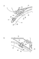
例えば、従来のカバー体には、図7(a)(一部断面側面図)に示すように、ロータリ作業体11の上方を覆うようにしてロータリ作業体11の前側から後側までを覆うゴム、合成樹脂等で形成された可撓板60と、この可撓板60の後端縁に取り付けられた横架部材に上下方向に回動自在に取り付けられた後部カバー61の内側に撓みを持たせて設けた可撓板62とを有して構成されたものや(特許文献1参照)、図7(b)(断面図)に示すように、ロータリ作業体11の上方を覆う上部カバー65の後端に前後方向に揺動自在に連結された後部カバー66と上部カバー65の途中部位に設けた係止部67間に亘って弾性樹脂材料で形成された案内プレート68を設けて構成されたものがある(特許文献2参照)。
For example, as shown in FIG. 7A (partial cross-sectional side view), the conventional cover body has rubber covering the
このような従来の耕耘作業機のうち特許文献1に記載のカバー体のうち後部カバー内側に設けられた可撓板は、その前後両端部が後部カバーに固定されているので、この可撓板の中間部に放てきされた土が衝突すると可撓板が撓んで可撓板への土付着の防止を図ることができるが、可撓板が固定された可撓板の端部は、撓むことができないので、土が僅かでも付着すると、作業の進行に伴って付着した土が次第に大きくなり、最終的には、ロータリ作業体に設けられた耕耘爪の先端が移動する回転軌跡の近くまで付着する。このため、耕耘爪が付着した土を掻き取り、所用動力が増大し、耕耘爪の摩耗速度が速くなって寿命が短くなるという問題が発生する。
Among such conventional tillage working machines, the flexible plate provided inside the rear cover of the cover body described in
また特許文献2に記載のカバー体を構成する案内プレートの後側端部も、特許文献1に記載の場合と同様に、後部カバーに着脱可能に固定されているので、案内プレートの固定された部分に土が付着すると、作業の進行に伴って付着した土が次第に大きくなって、耕耘爪の先端の回転軌跡の近くまで付着する。このため、耕耘爪が付着した土を掻き取って耕耘爪の摩耗が速くなって寿命が短くなり、所用動力が増大するという問題が発生する。
Moreover, since the rear side edge part of the guide plate which comprises the cover body of patent document 2 is also detachably fixed to the rear cover similarly to the case of
本発明は、このような問題に鑑みてなされたものであり、一番土が付着し易いカバー体の固定部分を少なくし、カバー体への土の付着が防止可能な耕耘作業機を提供することを目的とする。 The present invention has been made in view of such a problem, and provides a tilling work machine capable of reducing the fixing portion of the cover body to which the soil is most likely to adhere, and preventing the soil from adhering to the cover body. For the purpose.
このような課題を解決するため、本発明は、以下の特徴を有する。特徴の一つは、機体に回転自在に設けられたロータリ作業体と、該ロータリ作業体の上方を覆う上部カバーと、ロータリ作業体の背面側を覆い上部カバーの後端部に上下方向に回動自在に支持された後部カバーを備えた耕耘作業機において、上部カバー及び後部カバーの内面側に該上部カバーの前端から後部カバーの前側に亘って延設され、可撓性を有するカバー体と、カバー体の表面と後部カバーの内面との間に上部カバーから後部カバーの内面に沿って配設される弾性支持部材とを有し、カバー体は、その後端において、弾性支持部材に連結されて、後部カバーの内面に対して直接又は間接に接離自在であり、カバー体の前後方向中間部が弾性支持部材の前側端部とともに上部カバーに接続され、該上部カバーに接続された部分よりも後方側のカバー体の部分が腹になるように振動可能であることを特徴とする。 In order to solve such a problem, the present invention has the following features. One of the features is that the rotary work body is provided rotatably on the machine body, an upper cover that covers the upper part of the rotary work body, and a rear end portion of the upper cover that covers the back side of the rotary work body. In a tilling work machine having a rear cover that is movably supported, a flexible cover body that extends from the front end of the upper cover to the front side of the rear cover on the inner surface side of the upper cover and the rear cover. And an elastic support member disposed along the inner surface of the rear cover from the upper cover between the surface of the cover body and the inner surface of the rear cover, and the cover body is coupled to the elastic support member at the rear end. Te, Ri separable freely der directly or indirectly against the inner surface of the rear cover, the front-rear direction intermediate portion of the cover body is connected to the upper cover with the front end portion of the elastic support member, which is connected to the upper cover portion After Cover body portion side is characterized in that it is vibrating so that the belly.
この特徴によれば、上部カバー及び後部カバーの内面側に上部カバーの前端から後部カバーの前側に亘って延設されて可撓性を有するカバー体を設け、カバー体の表面と後部カバーの内面との間に上部カバーから後部カバーの内面に沿って配置される弾性支持部材を設け、カバー体は、その後端において、弾性支持部材に連結されて、後部カバーの内面に対して直接又は間接に接離自在であることにより、ロータリ作業体から放てきされた土がカバー体に衝突すると、カバー体は弾性支持部材とともに後部カバー側に撓み、弾性変形した弾性支持部材が元の位置に戻るに伴い、カバー体も元の位置に戻る。このため、ロータリ作業体から放てきされた土がカバー体に連続的に衝突すると、カバー体を振動させることができる。このときカバー体は振動の腹になり、振動の振幅は大きくなる。よって、ロータリ作業体から放てきされた土がカバー体に不着しようとしても、この振動によって、放てきされた土を弾き飛ばしたり付着力を弱めたりすることができる。このため、ロータリ作業体から放てきされた土がカバー体に不着するのを防止すてきされた土がカバー体に不着するのを防止することができる。 According to this feature, a flexible cover body extending from the front end of the upper cover to the front side of the rear cover is provided on the inner surface side of the upper cover and the rear cover, and the surface of the cover body and the inner surface of the rear cover are provided. An elastic support member disposed along the inner surface of the rear cover from the upper cover, and the cover body is connected to the elastic support member at the rear end thereof, directly or indirectly with respect to the inner surface of the rear cover When the soil released from the rotary work body collides with the cover body, the cover body bends to the rear cover side together with the elastic support member, and the elastically deformed elastic support member returns to the original position. Accordingly, the cover body also returns to the original position. For this reason, when the soil discharged from the rotary working body continuously collides with the cover body, the cover body can be vibrated. At this time, the cover body becomes an antinode of vibration, and the amplitude of vibration increases. Therefore, even if the soil released from the rotary working body is not attached to the cover body, this vibration can blow off the released soil or weaken the adhesive force. For this reason, it is possible to prevent the soil released from the rotary working body from being attached to the cover body.
またカバー体は、弾性支持部材によって支持されており、カバー体の支持機構は極めて簡単である。このため、カバー体を後部カバーに対して接離自在に支持する構造の部品数を少なくすることができ、耕耘作業機のコストアップを抑えることができる。 The cover body is supported by an elastic support member, and the support mechanism of the cover body is extremely simple. For this reason, it is possible to reduce the number of parts having a structure that supports the cover body so as to be able to contact and separate from the rear cover, and it is possible to suppress an increase in the cost of the tillage working machine.
また特徴の一つは、上部カバーに、その前側の端部から張り出し、可撓性を有する支持部材が固定され、この支持部材の先端部にカバー体が支持されていることを特徴とする。 Further, one of the features is that a flexible support member is fixed to the upper cover from its front end, and the cover body is supported at the tip of the support member.
この特徴によれば、上部カバーに、その前側の端部から張り出して可撓性を有する支持部材を固定し、この支持部材の先端部にカバー体を支持することにより、ロータリ作業体から放てきされた土がカバー体の前端部分に衝突すると、カバー体の前側は支持部材とともに上部カバー側に撓んで変形し、変形した支持部材及びカバー体は元の位置に戻る。このため、カバー体の前側にロータリ作業体から放てきされた土が連続的に衝突すると、カバー体の前側を振動させることができる。そして、カバー体は振動の腹になるので、振動の振幅が大きくなる。よって、ロータリ作業体から放てきされた土がカバー体に不着するのを防止することができる。 According to this feature, a flexible support member that protrudes from the front end of the upper cover is fixed to the upper cover, and the cover body is supported by the tip of the support member, so that it can be released from the rotary work body. When the soil thus made collides with the front end portion of the cover body, the front side of the cover body is bent and deformed together with the support member toward the upper cover side, and the deformed support member and the cover body are returned to their original positions. For this reason, when the soil discharged from the rotary working body continuously collides with the front side of the cover body, the front side of the cover body can be vibrated. And since a cover body becomes a vibration antinode, the amplitude of vibration becomes large. Therefore, it is possible to prevent the soil released from the rotary working body from adhering to the cover body.
また特徴の一つは、弾性支持部材の後部カバー側の表面に、緩衝部材が設けられていることを特徴とする。 One of the features is that a buffer member is provided on the surface of the elastic support member on the rear cover side.
この特徴によれば、弾性支持部材の後部カバー側の表面に緩衝部材を設けることにより、作業機の旋回時等において作業機自体を持ち上げるに伴って後部カバーがロータリ作業体側へ回動するに伴い、緩衝部材を後部カバーの内面に当接させて、緩衝部材が後部カバーに当接したときに発生する音を小さくすることができる。 According to this feature, by providing a cushioning member on the surface of the elastic support member on the rear cover side, as the work implement itself is lifted when the work implement is turned, the rear cover is rotated toward the rotary work body. The sound generated when the buffer member comes into contact with the rear cover can be reduced by bringing the buffer member into contact with the inner surface of the rear cover.
また特徴の一つは、弾性支持部材は、緩衝部材を該後部カバーの内面に接触させていることを特徴とする。 One of the characteristics is that the elastic support member makes the buffer member contact the inner surface of the rear cover.
この特徴によれば、弾性支持部材は、緩衝部材を該後部カバーの内面に接触させていることにより、耕耘作業時に圃場から後部カバーに伝わる振動を、緩衝部材を介してカバー体に伝達することができる。このため、耕耘作業時にカバー体を常に振動させることができ、ロータリ作業体から放てきされた土がカバー体に衝突することで発生するカバー体の振動と相まって、土の不着をより効果的に抑えることができる。また作業機の旋回時等において作業機自体を持ち上げるに伴って後部カバーがロータリ作業体側へ回動すると、弾性支持部材の後端が緩衝部材を介してロータリ作業体側へ押されて、弾性支持部材はロータリ作業体側へ撓む。これと同時に、カバー体はロータリ作業体側へ凸状に弯曲する。このため、カバー体の凸状に弯曲した外側の面は延びるように変形して、この外面に不着している土を落とすことができる。また弯曲したカバー体がロータリ作業体に設けられた爪と接触してカバー体に不着している土を落とすことができる。このため、カバー体に不着した土を効果的に落とすことができる。 According to this feature, the elastic support member makes the buffer member contact the inner surface of the rear cover, thereby transmitting the vibration transmitted from the farm field to the rear cover during the tilling work to the cover body via the buffer member. Can do. For this reason, the cover body can be vibrated at the time of tillage work, coupled with the vibration of the cover body that occurs when the soil released from the rotary work body collides with the cover body, and the soil non-sticking is more effectively performed. Can be suppressed. Further, when the rear cover rotates to the rotary work body side as the work machine is lifted up when the work machine is turned, the rear end of the elastic support member is pushed to the rotary work body side via the buffer member, and the elastic support member Bends toward the rotary work body. At the same time, the cover body is bent in a convex shape toward the rotary working body. For this reason, the outer surface bent in a convex shape of the cover body is deformed so as to extend, and the soil not attached to the outer surface can be dropped. Further, the bent cover body comes into contact with the claws provided on the rotary working body, and the soil not attached to the cover body can be removed. For this reason, the soil which did not adhere to the cover body can be effectively dropped.
本発明に係わる耕耘作業機によれば、上記特徴を有することにより、一番土が付着し易いカバー体の固定部分を少なくし、カバー体への土の付着の防止が可能な耕耘作業機を提供することができる。 According to the tillage working machine according to the present invention, the tilling work machine having the above-described features can reduce the fixed portion of the cover body to which the soil is most likely to adhere and prevent the soil from adhering to the cover body. Can be provided.
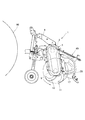
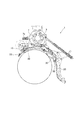
以下、本発明の好ましい実施の形態を図1〜図6に基づいて説明する。耕耘作業機1は、図1(作業機側方説明図)及び図2(側面図)に示すように、幅方向(左右方向)に延びる主フレーム3を有した機体5の前部に、走行機体90の後部に設けられた図示しない3点リンク連結機構に連結されるトップマスト6とロアーリンク連結部を設けて、走行機体90の後部に対して昇降可能に装着される。主フレーム3の左右方向の中央部には前方へ突出する入力軸7aを備えたギアボックス7が設けられ、走行機体90のPTO軸からユニバーサルジョイント等の動力伝達手段を介して動力が入力軸7aに伝達されるようになっている。
Hereinafter, a preferred embodiment of the present invention will be described with reference to FIGS. As shown in FIG. 1 (side view of the working machine) and FIG. 2 (side view), the
主フレーム3の一方側(左側)の端部には、チェーン伝動ケース9が垂設され、主フレーム3の他方側(右側)の端部には側部フレームがチェーン伝動ケース9と対向して垂設されている。チェーン伝動ケース9に接続された主フレーム3の左側の部分及びチェーン伝動ケース9内には伝動機構が設けられ、チェーン伝動ケース9と側部フレームの下端部間に多数の耕耘爪12を取り付けたロータリ作業体11が回転自在に設けられている。そして、入力軸7aに伝達された動力は、ギアボックス7を介して主フレーム3及びチェーン伝動ケース9内の伝動機構に伝達されて、ロータリ作業体11をダウンカット方向(反時計方向)に回転させる。
A chain transmission case 9 is suspended from one end (left side) of the
ロータリ作業体11の上側は、上部カバー15によって覆われ、この上部カバー15の左右方向両端部には側部カバー17が設けられている。上部カバー15は、ロータリ作業体11の前側から後方側に延び、上部カバー15の後端部には、後部カバー20が上下方向に回動自在に取り付けられている。
The upper side of the
後部カバー20は後端側が上部カバー15の後端から斜め下方へ延び、後部カバー20の後端部20aによって耕土表面を平らに整地する。機体5の幅方向内側には、後部カバー20の背面と主フレーム3との間に取り付けられて後部カバー20の傾き角度を調節する角度調節装置40が設けられている。
The rear end of the
後部カバー20の前側の内面はロータリ作業体11の背面側を覆う位置に配置されてロータリ作業体11から放てきされた土の飛散を防止する。
The inner surface on the front side of the
上部カバー15とこれに繋がる後部カバー20の内面よりも内側であって、ロータリ作業体11に設けられた耕耘爪12の先端の回転軌跡よりも外側の空間部には、上部カバー15の前端から後部カバー20の前側に亘って延びるカバー体30が設けられている。カバー体30は、ゴム材料製であって可撓性を有して板状に形成されたものであり、その前端部は、図3(a)(部分拡大断面図)に示すように、上部カバー15の前端部から張り出した支持部材23により支持されている。
From the front end of the
支持部材23は、ゴム材料製であって可撓性を有して板状に形成されたものであり、その後端部はボルト24・ナット25を介して上部カバー15の前端部に締結されて固定されている。支持部材23を上部カバー15に固定する際に、ボルト24による支持部材23への締結領域を拡大するために、ボルト頭部と接触する側が拡開したカラー26を介して支持部材23が上部カバー15に固定されている。
The
カバー体30の前端部は、これと支持部材23の前端部に挿通されたボルト24'にナット25'を螺合して支持部材23の前端部に固定されている。カバー体30を支持部材23に固定する際に、ボルト24'による支持部材23への締結範囲を拡大するために、ボルト頭部と接触する側が拡開したカラー26'と、ナット25'よりも大きな径を有したワッシャ27とを用いてカバー体30の前端部分が支持部材23に固定されている。
The front end portion of the
このように、カバー体30の前端部を、上部カバー15の前端部から張り出して可撓性を有する支持部材23の前端部に固定することで、カバー体30の前側を上下方向に移動可能に支持することができる。なお、カバー体30の前端部は、上部カバー15の前端部から張り出して可撓性を有するものであれば前述した支持部材23に限るものではなく、板ばねによって支持されてもよい。
In this manner, the front end portion of the
前後方向に延びるカバー体30の中間部のうち上部カバー15の後端部に対向する部分には、図3(b)(部分拡大断面図)に示すように、カバー体30の厚さよりも長く上部カバー15の後側の内面とカバー体30の表面との間に隙間31を形成可能なカラー32が挿通されている。このカラー32は、頭部が皿状のボルト34の軸部を通す筒状部32aと筒状部32aの基端側に繋がって外側に拡開するフランジ部32bを有して構成されている。ボルト34の軸部は、フランジ部32bから挿入されて筒状部32a及び上部カバー15を挿通し、上部カバー15に配設したナット25''に螺合して、カラー32を上部カバー15に固定するとともに、カバー体30の中間部を上部カバー15の後端部に対して接離自在にしている。
A portion of the intermediate portion of the
カバー体30の後側と上部カバー15の内面との間には、板ばねにより形成された弾性支持部材43が設けられている。この弾性支持部材43は、その前端側がカラー32と上部カバー15との間に挟持された状態で固定され、弾性支持部材43の後端側は、図1に示すように、後部カバー20の内面に沿って延びている。つまり、弾性支持部材43は上部カバー側の端部が固定され後部カバー側が自由な状態に支持されている。弾性支持部材43の後部カバー側の端部には、上方へ突出する緩衝部材50が設けられている。なお、緩衝部材50は、弾性支持部材43の後部カバー側の端部よりも上部カバー側に設けられてもよい。
An
弾性支持部材43は、耕耘作業時に作業姿勢にある後部カバー20の内面に緩衝部材50が接触した状態に維持されるように、弾性支持部材43の後部カバー側は後部カバー20の内面に向かって直線的又は僅かに下方へ撓んだ状態で延びるように取り付けられている。なお、後部カバー20は、作業姿勢にあるときは、上部カバー15に対して後方側へ回動して傾斜角度θの小さい斜め下方へ延びた状態になる。
The
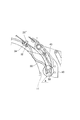
上部カバー15の後端部に取り付けられたカバー体30の後側は、弾性支持部材43の裏面側に沿って延びて、弾性支持部材43の先端部に取り付けられている。カバー体30の後側は、後部カバー20の作業姿勢時において弾性支持部材43よりも大きな撓みを有するように取り付けられている。このため、作業機の旋回時等において作業機自体を持ち上げるに伴って後部カバー20がロータリ作業体11側へ回動するに伴い、カバー体30の後側は大きくロータリ作業体11側に突出するように弯曲して図4に示す状態になる。即ち、カバー体30は、ロータリ作業体11側に撓むと、大きく弯曲した部分がロータリ作業体11の耕耘爪12の先端の回転軌跡の近傍まで移動する。
The rear side of the
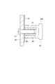
図5は、緩衝部材50が取り付けられたカバー体30の後端部分の断面図を示したものであり、同図に示すように、カバー体30の後端部分は、これと弾性支持部材43の後端部とを挿通するボルト51の先端部に緩衝部材50を螺合して弾性支持部材43の後端部に固定されている。
FIG. 5 shows a cross-sectional view of the rear end portion of the
緩衝部材50は、ゴム等の弾性を有した材料で形成され、キャップ状本体部52と、キャップ状本体部52の内部に挿着されてボルト51と螺合するナット部53とを備えて構成されている。キャップ状本体部52は内部にナット部53を挿着可能な穴部52aが設けられ、キャップ状本体部52の先端部には外側へ突出して円板状に形成された当接部52bが設けられている。緩衝部材50は、作業機の旋回時等において作業機自体が持ち上げられるに伴って図4に示す後部カバー20がロータリ作業体11側へ回動するに伴い、弾性支持部材43の先端部分が後部カバー20の内面に当接して大きな音を発生させない機能と、作業機の耕耘作業時において後部カバー20が圃場から受ける振動をカバー体30に伝達する機能を有している。
The
このように構成された耕耘作業機1によれば、図1に示すように、カバー体30の前端部は支持部材23を介して移動可能に支持され、カバー体30の中間部はカラー32を介して上部カバー15に対して移動可能に支持され、カバー体30の後端部は弾性支持部材43に連結されているので、カバー体30をカバーに固定する部分を殆ど無くすことができる。また、耕耘作業機1は、耕耘作業時において、ロータリ作業体11から放てきされた圃場の土が後部カバー20側へ延びるカバー体30に連続的に衝突すると、カバー体30の後側は弾性支持部材43とともに後部カバー20側に撓む。そして、弾性変形した弾性支持部材43が元の位置に戻るに伴い、カバー体30の後側も元の位置に戻り、この一連の動作が連続的に行われる。よって、カバー体30を振動させることができる。このときカバー体は振動の腹になり、振動の振幅は大きくなる。よって、ロータリ作業体から放てきされた土がカバー体に不着しようとしても、この振動によって、放てきされた土を弾き飛ばしたり付着力を弱めたりすることができる。このため、ロータリ作業体11から放てきされた土がカバー体30に不着するのを防止することができる。
According to the tilling
また耕耘作業時において、圃場の表面上を移動する後部カバー20は、圃場の表面を移動する際に振動を受ける。この振動は後部カバー20、緩衝部材50を介してカバー体30に伝達される。このため、カバー体30は、ロータリ作業体11から放てきされた土の衝突による振動と後部カバー20から伝達される振動によって、カバー体30への土の不着をより効果的に防止することができる。
Further, during the plowing operation, the
また耕耘作業時において、ロータリ作業体11から放てきされた圃場の土が上部カバー15の内側に延びるカバー体30に連続的に衝突すると、上部カバー15に対して接離自在に支持されたカバー体30が上部カバー15側に撓み、放てきされた土のエネルギを減少させて、土のカバー体30への不着を防止することができる。また、ロータリ作業体11から放てきされた圃場の土が上部カバー15の前端部分から張り出したカバー体30に連続的に衝突すると、このカバー体30が支持部材23とともに上方へ撓んで、放てきされた土のエネルギを減少させて、土のカバー体30への不着を防止することができる。
Further, when the soil in the field released from the
なお、作業機の旋回時等において作業機自体が持ち上げられるに伴って後部カバー20がロータリ作業体11側へ回動すると、図6に示すように、緩衝部材50を介して弾性支持部材43の先端側がロータリ作業体11側に押されて弾性支持部材43がロータリ作業体11側に撓むとともに、カバー体30はロータリ作業体11側に凸状に弯曲する。このため、カバー体30の凸状に弯曲した外側の面は延びるように変形し、この外面に不着している土を落とすことができる。また弯曲したカバー体30がロータリ作業体11に設けられた図2に示す耕耘爪12と接触してカバー体30に不着している土を落とすことができる。このため、カバー体30に不着した土を効果的に落とすことができる。
When the
また、カバー部30の前端部は、上部カバー15に対して、図3(a)に示す支持部材23、カラー26'、ボルト24'、ナット25'を介して接続され、カバー部30の中間部は、図3(b)に示すカラー32、ボルト34、ナット25''を介して接続され、カバー部30の後端部は図5に示すボルト51、弾性支持部材43、緩衝部材50を介して支持されており、いずれの部品も簡単な構造であり、汎用品も含まれている。このため、耕耘作業機1にカバー部30を設けてもコストの増大を抑制することができる。
Further, the front end portion of the
1 耕耘作業機
5 機体
11 ロータリ作業体
15 上部カバー
20 後部カバー
23 支持部材
30 カバー体
43 弾性支持部材
50 緩衝部材
DESCRIPTION OF
Claims (4)
前記上部カバー及び前記後部カバーの内面側に該上部カバーの前端から前記後部カバーの前側に亘って延設され、可撓性を有するカバー体と、
前記カバー体の表面と前記後部カバーの内面との間に前記上部カバーから前記後部カバーの内面に沿って配設される弾性支持部材とを有し、
前記カバー体は、その後端において、前記弾性支持部材に連結されて、前記後部カバーの内面に対して直接又は間接に接離自在であり、
前記カバー体の前後方向中間部が前記弾性支持部材の前側端部とともに前記上部カバーに接続され、該上部カバーに接続された部分よりも後方側の前記カバー体の部分が腹になるように振動可能である
ことを特徴とする耕耘作業機。 A rotary work body rotatably provided on the machine body, an upper cover that covers the upper side of the rotary work body, covers the back side of the rotary work body, and is supported by the rear end portion of the upper cover so as to be vertically rotatable. In the tilling machine with the rear cover made,
A flexible cover body extending from the front end of the upper cover to the front side of the rear cover on the inner surface side of the upper cover and the rear cover;
An elastic support member disposed along the inner surface of the rear cover from the upper cover between the surface of the cover body and the inner surface of the rear cover;
The cover member has at its rear end, said coupled to the elastic support member, Ri separable freely der directly or indirectly to the inner surface of said rear cover,
An intermediate portion in the front-rear direction of the cover body is connected to the upper cover together with a front end portion of the elastic support member, and vibrates so that a portion of the cover body on the rear side of the portion connected to the upper cover becomes an antinode. Is possible
Tillage work machine characterized by that.
Priority Applications (1)
| Application Number | Priority Date | Filing Date | Title |
|---|---|---|---|
| JP2008105565A JP5216396B2 (en) | 2008-04-15 | 2008-04-15 | Tillage work machine |
Applications Claiming Priority (1)
| Application Number | Priority Date | Filing Date | Title |
|---|---|---|---|
| JP2008105565A JP5216396B2 (en) | 2008-04-15 | 2008-04-15 | Tillage work machine |
Publications (2)
| Publication Number | Publication Date |
|---|---|
| JP2009254257A JP2009254257A (en) | 2009-11-05 |
| JP5216396B2 true JP5216396B2 (en) | 2013-06-19 |
Family
ID=41382520
Family Applications (1)
| Application Number | Title | Priority Date | Filing Date |
|---|---|---|---|
| JP2008105565A Active JP5216396B2 (en) | 2008-04-15 | 2008-04-15 | Tillage work machine |
Country Status (1)
| Country | Link |
|---|---|
| JP (1) | JP5216396B2 (en) |
Families Citing this family (2)
| Publication number | Priority date | Publication date | Assignee | Title |
|---|---|---|---|---|
| JP6914561B2 (en) * | 2016-06-07 | 2021-08-04 | 小橋工業株式会社 | Ridge coating machine |
| JP6792280B2 (en) * | 2016-06-07 | 2020-11-25 | 小橋工業株式会社 | Ridge coating machine |
Family Cites Families (3)
| Publication number | Priority date | Publication date | Assignee | Title |
|---|---|---|---|---|
| JPS60164805U (en) * | 1984-04-13 | 1985-11-01 | 松山株式会社 | tillage equipment |
| JP2518039Y2 (en) * | 1991-08-06 | 1996-11-20 | 松山株式会社 | Tillage equipment |
| JPH07255205A (en) * | 1994-03-16 | 1995-10-09 | Matsuyama Plow Mfg Co Ltd | Method for fluorescent labeling of sugar and rotary tiller |
-
2008
- 2008-04-15 JP JP2008105565A patent/JP5216396B2/en active Active
Also Published As
| Publication number | Publication date |
|---|---|
| JP2009254257A (en) | 2009-11-05 |
Similar Documents
| Publication | Publication Date | Title |
|---|---|---|
| JP5216396B2 (en) | Tillage work machine | |
| JP6483737B2 (en) | Rotary work machine | |
| JP6441578B2 (en) | Agricultural machine | |
| JP4208197B2 (en) | Soil adhesion prevention member for rotary cover | |
| US1041975A (en) | Cultivator-tooth. | |
| JP7351524B2 (en) | tillage equipment | |
| JP6061447B2 (en) | Rotary work machine | |
| JP4970393B2 (en) | Cover device for rotary tiller | |
| JP6721210B2 (en) | Rotary tiller | |
| JP4463184B2 (en) | Rotary tiller | |
| JP6968407B2 (en) | Agricultural work machine | |
| JP5746913B2 (en) | Rotary work machine | |
| JP6307555B2 (en) | Rotary work machine | |
| JP5936307B2 (en) | Apron material | |
| JP5996033B2 (en) | Rotary work machine | |
| JP5618906B2 (en) | Agricultural machine | |
| JP5021431B2 (en) | 畦 coating machine | |
| JP2006246746A (en) | Soil adhesion-preventing member for rear cover | |
| JP5936723B2 (en) | Apron material | |
| JP2017085979A (en) | Rotary tiller | |
| JPH119002A (en) | Fixation of elastic plate for preventing soil from sticking to rotary working machine | |
| JP2017051109A (en) | Agricultural implement | |
| JP2009183190A (en) | Skid of walking type tending machine | |
| JP3161389U (en) | Crushing claw with protrusions for tillers | |
| JPH04304801A (en) | Apparatus for covering rotary tiller |
Legal Events
| Date | Code | Title | Description |
|---|---|---|---|
| A621 | Written request for application examination |
Free format text: JAPANESE INTERMEDIATE CODE: A621 Effective date: 20110322 |
|
| A131 | Notification of reasons for refusal |
Free format text: JAPANESE INTERMEDIATE CODE: A131 Effective date: 20120417 |
|
| A977 | Report on retrieval |
Free format text: JAPANESE INTERMEDIATE CODE: A971007 Effective date: 20120418 |
|
| A521 | Request for written amendment filed |
Free format text: JAPANESE INTERMEDIATE CODE: A523 Effective date: 20120613 |
|
| TRDD | Decision of grant or rejection written | ||
| A01 | Written decision to grant a patent or to grant a registration (utility model) |
Free format text: JAPANESE INTERMEDIATE CODE: A01 Effective date: 20130205 |
|
| A61 | First payment of annual fees (during grant procedure) |
Free format text: JAPANESE INTERMEDIATE CODE: A61 Effective date: 20130304 |
|
| R150 | Certificate of patent or registration of utility model |
Ref document number: 5216396 Country of ref document: JP Free format text: JAPANESE INTERMEDIATE CODE: R150 Free format text: JAPANESE INTERMEDIATE CODE: R150 |
|
| FPAY | Renewal fee payment (event date is renewal date of database) |
Free format text: PAYMENT UNTIL: 20160308 Year of fee payment: 3 |
|
| RD03 | Notification of appointment of power of attorney |
Free format text: JAPANESE INTERMEDIATE CODE: R3D03 |
|
| R250 | Receipt of annual fees |
Free format text: JAPANESE INTERMEDIATE CODE: R250 |
|
| R250 | Receipt of annual fees |
Free format text: JAPANESE INTERMEDIATE CODE: R250 |
|
| R250 | Receipt of annual fees |
Free format text: JAPANESE INTERMEDIATE CODE: R250 |
|
| R250 | Receipt of annual fees |
Free format text: JAPANESE INTERMEDIATE CODE: R250 |
|
| R250 | Receipt of annual fees |
Free format text: JAPANESE INTERMEDIATE CODE: R250 |