JP5213249B2 - Pile head structure of precast concrete pile and pile head formation method - Google Patents
Pile head structure of precast concrete pile and pile head formation method Download PDFInfo
- Publication number
- JP5213249B2 JP5213249B2 JP2008321866A JP2008321866A JP5213249B2 JP 5213249 B2 JP5213249 B2 JP 5213249B2 JP 2008321866 A JP2008321866 A JP 2008321866A JP 2008321866 A JP2008321866 A JP 2008321866A JP 5213249 B2 JP5213249 B2 JP 5213249B2
- Authority
- JP
- Japan
- Prior art keywords
- sleeve
- pile
- screw
- end plate
- bolt
- Prior art date
- Legal status (The legal status is an assumption and is not a legal conclusion. Google has not performed a legal analysis and makes no representation as to the accuracy of the status listed.)
- Active
Links
- 239000011178 precast concrete Substances 0.000 title claims description 10
- 238000000034 method Methods 0.000 title claims description 7
- 230000015572 biosynthetic process Effects 0.000 title description 2
- 239000004567 concrete Substances 0.000 claims description 54
- 230000003014 reinforcing effect Effects 0.000 claims description 41
- 238000002788 crimping Methods 0.000 claims description 33
- 229910001294 Reinforcing steel Inorganic materials 0.000 claims description 13
- 238000009415 formwork Methods 0.000 claims description 2
- 229910000831 Steel Inorganic materials 0.000 description 29
- 239000010959 steel Substances 0.000 description 29
- 239000002131 composite material Substances 0.000 description 18
- 238000010276 construction Methods 0.000 description 6
- 230000008878 coupling Effects 0.000 description 6
- 238000010168 coupling process Methods 0.000 description 6
- 238000005859 coupling reaction Methods 0.000 description 6
- 230000002093 peripheral effect Effects 0.000 description 6
- 238000003466 welding Methods 0.000 description 4
- 230000002787 reinforcement Effects 0.000 description 3
- 238000005520 cutting process Methods 0.000 description 2
- 238000005304 joining Methods 0.000 description 2
- 238000004519 manufacturing process Methods 0.000 description 2
- 238000000465 moulding Methods 0.000 description 2
- 238000003825 pressing Methods 0.000 description 2
- 238000006073 displacement reaction Methods 0.000 description 1
- 239000002184 metal Substances 0.000 description 1
- 230000002265 prevention Effects 0.000 description 1
Images


Description
本発明は、既成コンクリート杭の杭頭部構造に関し、特に、フーチングとの結合用杭頭部を備えた既成コンクリート杭の杭頭部構造及び杭頭部形成方法に関する。 The present invention relates to a pile head structure of a precast concrete pile, and more particularly to a pile head structure of a precast concrete pile having a pile head for coupling with a footing and a pile head forming method.
例えば、鋼管を外殻とし、該鋼管内にコンクリートを打設して遠心力成形により一体化した鋼管コンクリート複合杭は建築及び土木の分野で広く用いられている。この鋼管コンクリート複合杭を基礎杭として使用した場合、杭とフーチングとを結合する関係上、杭の頭部近傍の鋼管をカットオフした後、コンクリート部分をハツリ取り、杭体内にあって前記鋼管の内側面に予め溶着したフーチング結合用の補強鉄筋を露出せしめるか、或いは鋼管の外周にフーチング結合用補強鉄筋を溶接すること(杭外周溶接鉄筋)で、杭とフーチングとを前記フーチング結合用補強鉄筋を介して結合している。。 For example, steel pipe-concrete composite piles, in which a steel pipe is used as an outer shell, concrete is cast in the steel pipe and integrated by centrifugal force forming, are widely used in the fields of construction and civil engineering. When this steel pipe-concrete composite pile is used as a foundation pile, the steel pipe near the head of the pile is cut off because of the connection between the pile and the footing. Expose the reinforcing reinforcing bar for the footing joint that has been welded to the inner surface in advance, or weld the reinforcing reinforcing element for the footing joint to the outer periphery of the steel pipe (pile outer peripheral welding reinforcing bar). Are connected through. .
一方、ネジ鉄筋をカプラーで固定する方法では、鋼管杭を対象とし、杭頭部外周に接続具(垂直ブランケット)を取付け、接続具の上面に螺旋状の節を形成した鉄筋を螺合する螺孔(雌ネジ付カプラー)を設け、フーチング結合用補強鉄筋下端部の雄ネジ部をネジ込む方式が知られている。その他、フーチング結合用補強鉄筋となる異形鋼棒端部に溶接し易い金物を摩擦圧接によって一体化し、施工後の外殻鋼管頭部外周に前記金物を溶接する方法や、杭頭端板に回転埋設用キャップに嵌合すると同時にフーチング結合用補強鉄筋をナット固定するボルト穴を設けたものが知られている。 On the other hand, in the method of fixing screw rebars with a coupler, a steel pipe pile is targeted, a connecting tool (vertical blanket) is attached to the outer periphery of the pile head, and a screw that forms a spiral node on the upper surface of the connecting tool is screwed together. There is known a system in which a hole (coupler with a female thread) is provided and a male thread portion at the lower end of a reinforcing bar for footing connection is screwed. In addition, it is possible to integrate metal parts that are easily welded to the ends of deformed steel rods that serve as reinforcing reinforcing bars for the footing connection by friction welding, and to weld the hardware to the outer periphery of the outer shell steel pipe head after construction. It is known that a bolt hole for fixing a reinforcing reinforcing bar for footing coupling is provided at the same time as fitting with a buried cap.
しかし、杭とフーチングとの結合作業時において、従来の鋼管コンクリート複合杭にあっては、カットオフ部位の鋼管を切断するための鋼管切断作業ならびにカットオフした鋼管の外周にフーチング結合用の補強鉄筋を溶着するための補強鉄筋溶接作業にそれぞれ多大な時間と労力を必要とするといった諸問題点がある。また、ネジ鉄筋をカプラーで固定する方法は、あくまで従来の杭外周溶接鉄筋の替わりを担うものであって、杭体内補強鉄筋や中詰め補強鉄筋とは異なり、公的審査を経る必要がある。 However, in the conventional steel pipe-concrete composite pile at the time of joining work between the pile and the footing, the steel pipe cutting work for cutting the steel pipe at the cut-off site and the reinforcing steel bar for joining the footing on the outer periphery of the cut-off steel pipe. There are various problems such as requiring a great amount of time and labor for the reinforcing bar welding work for welding the steel. In addition, the method of fixing the screw rebar with a coupler is merely a replacement of the conventional pile outer periphery welded rebar, and it is necessary to go through an official examination, unlike the reinforcing steel reinforcement in the pile and the filling reinforcing steel in the inside of the pile.
本発明は、従来の杭体内補強鉄筋の考え方を踏襲しつつ、かつハツリ作業がなく、継手手段として既に公的な評価を得た方法を採用するものとして、既成コンクリート杭の端板にスリーブ圧着ネジ継手を装着し、これに圧着された補強鉄筋をコンクリート部の一端に埋設した構成とし、施工後にスリーブ圧着ネジ継手のネジ部にフーチング結合用の補強鉄筋を容易に継ぎ足せるようにしたものである。 The present invention is based on the conventional concept of reinforcing steel bars in piles, and there is no chipping work, and a method that has already been officially evaluated as a joint means is adopted. A threaded joint is attached, and the reinforcing bar that is crimped to this is embedded in one end of the concrete part. After the construction, the reinforcing part for the footing connection can be easily added to the threaded part of the sleeve crimped threaded joint. is there.
上記の目的を達成するため、本願の請求項1に係る発明は、既成コンクリート杭の端板に取付孔を穿設するとゝもに、該取付孔の部分にコンクリート部に定着された杭体内補強鉄筋の一端を連結してなるスリーブ圧着ネジ継手を固定手段により固定してなり、前記固定手段が、鍔とその上下面から突出するボルト部からなる接続ボルトの一方のボルト部を、前記スリーブ圧着ネジ継手のスリーブネジ部の雌ねじに前記端板の取付孔を通して前記鍔までねじ込み、該鍔と前記スリーブ圧着ネジ継手のスリーブネジ部の端面とで前記端板を上下から挟持し前記端板に固定したことを特徴とする既成コンクリート杭の杭頭部構造である。 In order to achieve the above object, the invention according to claim 1 of the present application is to reinforce a pile body fixed to a concrete portion at a portion of the mounting hole when a mounting hole is drilled in an end plate of an existing concrete pile. A sleeve crimping screw joint formed by connecting one end of a reinforcing bar is fixed by a fixing means, and the fixing means fixes one bolt portion of a connection bolt composed of a flange and a bolt portion protruding from the upper and lower surfaces thereof to the sleeve crimping. Screw into the female thread of the sleeve thread part of the threaded joint through the mounting hole of the end plate to the flange, and clamp the end plate from above and below between the flange and the end surface of the sleeve threaded part of the sleeve crimped threaded joint and fix it to the end plate. It is a pile head structure of a prefabricated concrete pile characterized by the above.
また、本願の請求項2に係る発明は、既成コンクリート杭の端板に取付孔を穿設するとゝもに、該取付孔の部分にコンクリート部に定着された杭体内補強鉄筋の一端を連結してなるスリーブ圧着ネジ継手を固定手段により固定してなり、前記固定手段が、前記端板の取付孔に挿入した固定ボルトを前記スリーブ圧着ネジ継手のスリーブネジ部の雌ねじにねじ込み、前記固定ボルトの頭部と前記スリーブ圧着ネジ継手のスリーブネジ部の端面とで前記端板を上下から挟持し前記端板に固定したことを特徴とする既成コンクリート杭の杭頭部構造としたものである。
In the invention according to
そして、上記の目的を達成するため、本願の請求項3に係る発明は、前記端板の取付孔の部分に固定した前記スリーブ圧着ネジ継手のスリーブネジ部の雌ねじに、鍔部とその上下面から突出するボルト部からなる接続ボルトの一方のボルト部をねじ込んで連結するとゝもに、他方のボルト部を、フーチング部に埋め込まれる補強鉄筋の一端を固定した接続側のスリーブ圧着ネジ継手のスリーブネジ部の雌ねじにねじ込み、前記両スリーブ圧着ネジ継手を前記接続ボルトを介して前記両補強鉄筋を連結する構成としたことを特徴とする既成コンクリート杭の杭頭部構造である。
In order to achieve the above object, the invention according to
更に、本願の請求項4に係る発明は、既成コンクリート杭の端板に形成した取付孔内に、杭体内補強鉄筋の上端部を圧着により連結したスリーブ圧着ネジ継手のスリーブネジ部を挿通する工程、前記スリーブ圧着ネジ継手のスリーブネジ部の雌ねじ内に、鍔とその上下面から突出するボルト部からなる接続ボルトの下方のボルト部を前記鍔が前記端板の上面と当接するまでねじ込む工程、前記既成コンクリート杭の型枠内にコンクリートを打設する工程、前記コンクリートを固化せしめて前記杭体内補強鉄筋をコンクリート部に定着させる工程、以上の各工程を順次経ることを特徴とする既成コンクリート杭の杭頭部形成方法である。 Furthermore, in the invention according to claim 4 of the present application, the step of inserting the sleeve screw portion of the sleeve crimp screw joint in which the upper end portion of the reinforcing bar in the pile is connected by crimping into the mounting hole formed in the end plate of the precast concrete pile. Screwing the lower bolt portion of the connecting bolt composed of the flange and the bolt portion protruding from the upper and lower surfaces thereof into the female thread of the sleeve screw portion of the sleeve crimped screw joint until the flange contacts the upper surface of the end plate ; A step of placing concrete in a formwork of the prefabricated concrete pile, a step of solidifying the concrete and fixing the reinforcing bar in the pile to a concrete part, and the above steps are sequentially performed. It is a pile head formation method.
本願の発明は、上記のように、既成コンクリート杭の端板に形成した取付孔の部分に、コンクリート部に定着された杭体内補強鉄筋の一端を連結してなるスリーブ圧着ネジ継手を、請求項1又は2記載の固定手段により固定してなる構成であるから、既成コンクリート杭の成型時にその端板の取付孔の部分にスリーブ圧着ネジ継手を装着しておくだけの簡単な構造で済むとゝもに、既成コンクリート杭の施工後に、前記スリーブ圧着ネジ継手に接続ボルトを用い、該接続ボルトに、フーチング部に埋め込まれる補強鉄筋を備えた接続側のスリーブ圧着ネジ継手をねじ込むことで容易に接続することができる。 As described above, the invention of the present application claims a sleeve crimped screw joint formed by connecting one end of a reinforcing bar in a pile fixed to a concrete portion to a portion of an attachment hole formed in an end plate of an existing concrete pile. Since the structure is fixed by the fixing means described in 1 or 2, it is only necessary to have a simple structure in which a sleeve crimped screw joint is attached to the mounting hole portion of the end plate when molding an existing concrete pile. In addition, after the construction of the prefabricated concrete pile, a connection bolt is used for the sleeve crimping screw joint, and the connection side sleeve crimping screw joint with a reinforcing bar embedded in the footing part is screwed into the connection bolt for easy connection. can do.
また、前記スリーブ圧着ネジ継手が前記端板に又は端板を介して前記接続ボルトなどによって固定されている構造としていることから、前記スリーブ圧着ネジ継手を杭の成型時に簡単に設置することで形成できるとゝもに、フーチング部に埋め込まれる補強鉄筋を備えた接続側のスリーブ圧着ネジ継手を連結するための接続ボルトを埋込み側のスリーブ圧着ネジ継手にねじ込でおくことで、スリーブ圧着ネジ継手を杭頭端板に固定する機能と、杭の製造から施工までの間に雌ネジ穴を防ぐ機能と、かつ現場で接続継手を取付けることなく直ちにフーチング部に埋め込まれる異形鉄筋を接続できる。 In addition, since the sleeve crimped screw joint is fixed to the end plate or via the end plate by the connection bolt or the like, the sleeve crimped screw joint is formed by simply installing the pile when the pile is formed. If possible, connect the connection bolt to connect the sleeve crimp screw joint on the connection side with the reinforcing bar embedded in the footing part into the sleeve crimp screw joint on the embedding side. Can be connected to the pile head end plate, the function of preventing the female screw hole from the manufacturing to the construction of the pile, and the deformed reinforcing bar embedded in the footing part immediately without attaching the connecting joint on site.
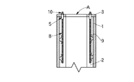
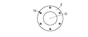
以下、本発明を図面に示す実施形態により詳細に説明する。図1乃至図3において、Aは外側を覆っている鋼管1とコンクリート部2からなる鋼管コンクリート複合杭で、該鋼管コンクリート複合杭Aの上端部端面にはドーナツ型の端板3が装着されている。4は前記端板3に形成した複数の取付孔で、図示の実施例では、複合杭Aの中心Oを中心とする中心角が60度の等間隔をおいて6個穿設されており、これらの各取付孔4の部分には後述するスリーブ圧着ネジ継手がそれぞれ固定されている。
Hereinafter, the present invention will be described in detail with reference to embodiments shown in the drawings. 1 to 3, A is a steel pipe concrete composite pile comprising a steel pipe 1 and a
5はスリーブ圧着ネジ継手で、図3に示す実施形態では、スリーブの内周面に雌ねじ6Aを形成した上方のスリーブねじ部6と、スリーブの内周面に凹凸を形成した下方のスリーブ圧着部7とから構成されている。そして更に、前記スリーブ圧着ネジ継手5の外周面には雄ねじ5Aが形成されており、該雄ねじ5Aを前記端板3の取付孔4に形成した雌ねじ4Aにねじ込むことで、前記スリーブ圧着ネジ継手5を前記端板3の取付孔4に直接固定した構造としている。
8は杭体内補強鉄筋で、図1に示すように、前記鋼管コンクリート複合杭Aの内部のコンクリート部2と定着しており、該杭体内補強鉄筋8にあって、前記スリーブ圧着ネジ継手5のスリーブ圧着部7内に挿入した前記杭体内補強鉄筋8の上端部8Aを前記スリーブ圧着部7の外周側から圧着することで、前記杭体内補強鉄筋8が前記スリーブ圧着ネジ継手5に固定され一体に連結されている。なお、図中9は鋼管コンクリート複合杭Aを成形する際に、前記杭体内補強鉄筋8を所定位置に固定するためのずれ止め治具であり、10は前記スリーブ圧着ネジ継手5のスリーブねじ部6の雌ねじ6Aにねじ込んだ接続ボルトである。
As shown in FIG. 1,
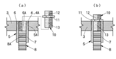
上記接続ボルト10は、ねじ棒の長手方向の中央部に鍔11を備え、該鍔11の中心部にあってその上下両面に上部ねじ12と下部ねじ13がそれぞれ上下に突設した構造のものであり、図3(a)(b)に示すように、前記接続ボルト10の下部ねじ13を、鍔11が端板3の上面と当接するまでスリーブ圧着ネジ継手5の前記雌ねじ6Aにねじ込んである。この接続ボルト10は、杭の製造から施工までの間に前記スリーブ圧着ネジ継手5の、前記端板3に形成した取付孔4の部分に開口する雌ねじ6Aの孔を塞ぐ機能と、接続する側のスリーブ圧着ネジ継手を杭頭の前記端板3に固定する機能をも果たしている。
The
図4は本発明に係る鋼管コンクリート複合杭Aの杭頭部の他の実施例で、前記図1乃至3に示す杭頭部と相違する点は、前記スリーブ圧着ネジ継手5の端板3への固定構造にある。すなわち、図4において、15はスリーブ圧着ネジ継手で、そのスリーブねじ部16を鋼管コンクリート複合杭Aの端板3に形成した取付孔14内に挿通しており、このスリーブねじ部16の雌ねじ16A内に前記接続ボルト10の下部ねじ13を鍔11が端板3の上面と当接するまでねじ込んである。
FIG. 4 shows another embodiment of the pile head of the steel pipe concrete composite pile A according to the present invention. The difference from the pile head shown in FIGS. 1 to 3 is that the
これにより、前記杭体内補強鉄筋8はスリーブ圧着ネジ継手15および接続ボルト10を介して前記端板3に図4に示す状態で設置されることになる。そして、この状態で前記鋼管コンクリート複合杭Aの図示しない成形用の型枠内にコンクリートを打設し、該コンクリートが固化することで前記杭体内補強鉄筋8はコンクリート部2に定着される。杭体内補強鉄筋8がコンクリート部2に定着された結果、該杭体内補強鉄筋8の上端部8Aで連結された前記スリーブ圧着ネジ継手15も同時に図4に示す状態で前記端板3に固定されることになる。
As a result, the reinforcing
図5は本発明に係る鋼管コンクリート複合杭の杭頭部の更に他の実施例で、前記図3および図4に示す杭頭部構造とは、前記スリーブ圧着ネジ継手5の端板3への固定構造において相違している。すなわち、図5において、25はスリーブ圧着ネジ継手で、そのスリーブねじ部26の上端面を鋼管コンクリート複合杭Aの端板3に形成した取付孔14の下面周囲と当接せしめるとゝもに、そのスリーブねじ部26の雌ねじ26Aに前記接続ボルト10の下部ねじ13を鍔11が端板3の上面と当接するまでねじ込んである。
FIG. 5 shows still another embodiment of the pile head of the steel pipe concrete composite pile according to the present invention. The pile head structure shown in FIG. 3 and FIG. There is a difference in the fixed structure. That is, in FIG. 5, 25 is a sleeve crimping screw joint, and when the upper end surface of the
これにより、前記接続ボルト10の鍔11の下面とスリーブ圧着ネジ継手25のスリーブねじ部26の端面とで前記端板3を上下から挟み付ける構造で設置され、スリーブ圧着ネジ継手25は端板5の取付孔14き部分に固定される。
Accordingly, the
そして又、図6は本発明に係る鋼管コンクリート複合杭の杭頭部の更なる他の実施例である。詳述すると、図6に示す実施形態のものは、前記図5に示す前記接続ボルト10に代えて固定ボルト35によりスリーブ圧着ネジ継手25を端板3に固定したものである。すなわち、スリーブ圧着ネジ継手25は、前記図5に示す実施形態の場合と同様に、スリーブねじ部26の端面を鋼管コンクリート複合杭Aの端板3に形成した取付孔14の下面周縁と当接せしめる。
FIG. 6 shows still another embodiment of the pile head of the steel pipe concrete composite pile according to the present invention. More specifically, in the embodiment shown in FIG. 6, the sleeve crimping screw joint 25 is fixed to the
そして、そのスリーブねじ部26の雌ねじ26Aに端板3側から取付孔14に固定ボルト35を挿入し、該固定ボルト35を締め付けることで、前記固定ボルト35の頭部35Aとスリーブ圧着ネジ継手25のスリーブねじ部26の端面とで前記端板3を上下から挟み付け、スリーブ圧着ネジ継手25を端板3に固定したものである。なお、前記固定ボルト35は、鋼管コンクリート複合杭の成型時に、前記杭体内補強鉄筋8が打設したコンクリートが固化しコンクリート部2に定着された時点で、これを前記スリーブねじ部26から取り外すことが可能となる。
Then, the fixing
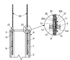
つぎに、上記のように、前記鋼管コンクリート複合杭Aの端板3に、例えばスリーブ圧着ネジ継手15を接続ボルト10を介して固定した図4に示す構造の杭頭部に、フーチングと結合するフーチング結合用の補強鉄筋36を連結する場合について、図7に示す実施形態により以下に説明すると、前記スリーブ圧着ネジ継手15のスリーブねじ部16(雌ねじ16A)に下部ねじ13をねじ結合によって取り付けた接続ボルト10の上部ねじ12に、前記フーチング結合用の補強鉄筋36の下端36Aを圧着して固定した前記スリーブ圧着ネジ継手15と同一構造の接続側のスリーブ圧着ネジ継手37を使用する。
Next, as described above, the footing is coupled to the pile head having the structure shown in FIG. 4 in which, for example, the sleeve crimping screw joint 15 is fixed to the
詳述すると、前記スリーブ圧着ネジ継手37のスリーブネジ部38の雌ねじ38Aを、前記接続ボルト10の上部ねじ12に、接続ボルト10の鍔11の上面と当接するまでねじ込む。これにより、フーチングと結合するフーチング結合用の補強鉄筋36は、図7に示すように、接続する側のスリーブ圧着ネジ継手37,接続ボルト10およびスリーブ圧着ネジ継手15を介して前記杭体内補強鉄筋8と一体に連結される。
More specifically, the
1 鋼管コンクリート複合杭
2 コンクリート部
3 端板
4,14, 取付孔
4A 雌ねじ
5・15・25 スリーブ圧着ネジ継手
5A 雄ねじ
6・16・26 スリーブねじ部
6A・16A・26A 雌ねじ
7 スリーブ圧着部
8・36 補強鉄筋
8A・38A 同上端部
10 接続ボルト
11 鍔
12 上部ねじ
13 下部ねじ
DESCRIPTION OF SYMBOLS 1 Steel pipe concrete
Claims (4)
Priority Applications (1)
| Application Number | Priority Date | Filing Date | Title |
|---|---|---|---|
| JP2008321866A JP5213249B2 (en) | 2008-12-18 | 2008-12-18 | Pile head structure of precast concrete pile and pile head formation method |
Applications Claiming Priority (1)
| Application Number | Priority Date | Filing Date | Title |
|---|---|---|---|
| JP2008321866A JP5213249B2 (en) | 2008-12-18 | 2008-12-18 | Pile head structure of precast concrete pile and pile head formation method |
Publications (2)
| Publication Number | Publication Date |
|---|---|
| JP2010144391A JP2010144391A (en) | 2010-07-01 |
| JP5213249B2 true JP5213249B2 (en) | 2013-06-19 |
Family
ID=42565096
Family Applications (1)
| Application Number | Title | Priority Date | Filing Date |
|---|---|---|---|
| JP2008321866A Active JP5213249B2 (en) | 2008-12-18 | 2008-12-18 | Pile head structure of precast concrete pile and pile head formation method |
Country Status (1)
| Country | Link |
|---|---|
| JP (1) | JP5213249B2 (en) |
Families Citing this family (6)
| Publication number | Priority date | Publication date | Assignee | Title |
|---|---|---|---|---|
| CN104695459A (en) * | 2013-12-10 | 2015-06-10 | 江苏建华管桩有限公司 | Connection method of concrete precast pile and pile foundation cap |
| JP6395464B2 (en) * | 2014-06-18 | 2018-09-26 | 大成建設株式会社 | Steel pipe concrete pile joint structure |
| CN107254873A (en) * | 2017-07-25 | 2017-10-17 | 连云港建筑设计研究院有限责任公司 | Mechanical connecting structure of cushion cap anchor rib and stake top and attaching method thereof |
| CN109629589B (en) * | 2018-12-29 | 2024-01-16 | 国网山东省电力公司烟台供电公司 | Inserted prefabricated pile foundation |
| CN110258608A (en) * | 2019-06-12 | 2019-09-20 | 南通大学 | A kind of new device that prestressed pile is connect with cushion cap or bottom plate |
| CN114718059B (en) * | 2022-05-05 | 2023-03-21 | 广州建筑股份有限公司 | Tubular pile connecting structure and pile splicing method thereof |
Family Cites Families (3)
| Publication number | Priority date | Publication date | Assignee | Title |
|---|---|---|---|---|
| JPH02161010A (en) * | 1988-12-12 | 1990-06-20 | Masayo Tanaka | Edge stracture of precast concrete pile using prestressed coupler nut |
| JPH05306527A (en) * | 1992-04-30 | 1993-11-19 | Nippon Concrete Ind Co Ltd | Concrete pile |
| JP4808320B2 (en) * | 2001-03-05 | 2011-11-02 | 岡部株式会社 | Adjustable coupling structure between steel pipe pile and anchoring reinforcement |
-
2008
- 2008-12-18 JP JP2008321866A patent/JP5213249B2/en active Active
Also Published As
| Publication number | Publication date |
|---|---|
| JP2010144391A (en) | 2010-07-01 |
Similar Documents
| Publication | Publication Date | Title |
|---|---|---|
| JP5213249B2 (en) | Pile head structure of precast concrete pile and pile head formation method | |
| KR20100037696A (en) | A embeded anchor | |
| JP6691880B2 (en) | Precast wall balustrade mounting structure and mounting method | |
| JP2010174474A (en) | Prestressed concrete pile, method of manufacturing the same, and connection structure between pile and footing | |
| JP5041796B2 (en) | Method and structure for joining precast reinforced concrete beam members | |
| JP5236152B2 (en) | Method of joining precast concrete column beams | |
| JP3649717B2 (en) | Joints and structures for joining steel pipe pile heads to concrete foundations | |
| JPH07292783A (en) | Connective structure of prestressed concrete members | |
| JP5553702B2 (en) | Connection method and connection structure of precast slab with loop joint | |
| KR20140058076A (en) | Construction method for connecting new and old concrete | |
| JP4447632B2 (en) | Beam and beam-column joint structure and method of joining the same | |
| KR100710583B1 (en) | Hybrid system of pc column and steel beam | |
| JP4452060B2 (en) | Steel pipe pile head joint structure and steel pipe pile head construction method | |
| JP2005200994A (en) | Joining structure of closed cross-sectional member | |
| JP2004285823A (en) | Floor slab bridge and floor slab unit | |
| JP2004162345A (en) | Joining method and joint structure for prefabricated pile and foundation | |
| JP2012246676A (en) | Mechanical reinforcement joint | |
| JP4578029B2 (en) | Pile head structure and pile head bracket | |
| JPH1121915A (en) | Connecting method of pile head | |
| JP4469058B2 (en) | Connection method of precast concrete members | |
| JP4455702B2 (en) | Fitting and its connection method | |
| KR20090006472U (en) | Apparatus for Reinforcing Head of Steel Tube Pile | |
| KR100509262B1 (en) | The apparatus of attaching between concrete and steel structural members and attaching method | |
| JP2006200270A (en) | Joining structure and joining method | |
| KR200245357Y1 (en) | Steel Couplers for Steel Pipe Piles |
Legal Events
| Date | Code | Title | Description |
|---|---|---|---|
| A621 | Written request for application examination |
Free format text: JAPANESE INTERMEDIATE CODE: A621 Effective date: 20111212 |
|
| A977 | Report on retrieval |
Free format text: JAPANESE INTERMEDIATE CODE: A971007 Effective date: 20121019 |
|
| A131 | Notification of reasons for refusal |
Free format text: JAPANESE INTERMEDIATE CODE: A131 Effective date: 20121030 |
|
| A521 | Request for written amendment filed |
Free format text: JAPANESE INTERMEDIATE CODE: A523 Effective date: 20121126 |
|
| TRDD | Decision of grant or rejection written | ||
| A01 | Written decision to grant a patent or to grant a registration (utility model) |
Free format text: JAPANESE INTERMEDIATE CODE: A01 Effective date: 20130129 |
|
| A61 | First payment of annual fees (during grant procedure) |
Free format text: JAPANESE INTERMEDIATE CODE: A61 Effective date: 20130225 |
|
| R150 | Certificate of patent or registration of utility model |
Ref document number: 5213249 Country of ref document: JP Free format text: JAPANESE INTERMEDIATE CODE: R150 Free format text: JAPANESE INTERMEDIATE CODE: R150 |
|
| FPAY | Renewal fee payment (event date is renewal date of database) |
Free format text: PAYMENT UNTIL: 20160308 Year of fee payment: 3 |
|
| FPAY | Renewal fee payment (event date is renewal date of database) |
Free format text: PAYMENT UNTIL: 20160308 Year of fee payment: 3 |
|
| S111 | Request for change of ownership or part of ownership |
Free format text: JAPANESE INTERMEDIATE CODE: R313111 |
|
| FPAY | Renewal fee payment (event date is renewal date of database) |
Free format text: PAYMENT UNTIL: 20160308 Year of fee payment: 3 |
|
| R350 | Written notification of registration of transfer |
Free format text: JAPANESE INTERMEDIATE CODE: R350 |
|
| R250 | Receipt of annual fees |
Free format text: JAPANESE INTERMEDIATE CODE: R250 |
|
| R250 | Receipt of annual fees |
Free format text: JAPANESE INTERMEDIATE CODE: R250 |
|
| R250 | Receipt of annual fees |
Free format text: JAPANESE INTERMEDIATE CODE: R250 |
|
| R250 | Receipt of annual fees |
Free format text: JAPANESE INTERMEDIATE CODE: R250 |
|
| R250 | Receipt of annual fees |
Free format text: JAPANESE INTERMEDIATE CODE: R250 |
|
| R250 | Receipt of annual fees |
Free format text: JAPANESE INTERMEDIATE CODE: R250 |
|
| R250 | Receipt of annual fees |
Free format text: JAPANESE INTERMEDIATE CODE: R250 |
|
| R250 | Receipt of annual fees |
Free format text: JAPANESE INTERMEDIATE CODE: R250 |
|
| R250 | Receipt of annual fees |
Free format text: JAPANESE INTERMEDIATE CODE: R250 |