JP5212403B2 - Steering device - Google Patents
Steering device Download PDFInfo
- Publication number
- JP5212403B2 JP5212403B2 JP2010041628A JP2010041628A JP5212403B2 JP 5212403 B2 JP5212403 B2 JP 5212403B2 JP 2010041628 A JP2010041628 A JP 2010041628A JP 2010041628 A JP2010041628 A JP 2010041628A JP 5212403 B2 JP5212403 B2 JP 5212403B2
- Authority
- JP
- Japan
- Prior art keywords
- vehicle body
- steering
- column
- inner column
- mounting bracket
- Prior art date
- Legal status (The legal status is an assumption and is not a legal conclusion. Google has not performed a legal analysis and makes no representation as to the accuracy of the status listed.)
- Expired - Fee Related
Links
Images


Description
本発明はステアリング装置、特に、アウターコラムとインナーコラムが軸方向に摺動可能に嵌合することによって、ステアリングホイールのテレスコピック位置の調整を行うとともに、二次衝突時に、ステアリングホイールが車体前方側にコラプス移動して衝撃荷重を吸収するようにしたステアリング装置に関する。 The present invention adjusts the telescopic position of a steering wheel by fitting an outer column and an inner column so as to be slidable in the axial direction, and at the time of a secondary collision, the steering wheel is moved forward of the vehicle body. The present invention relates to a steering apparatus that absorbs impact loads by collapsing.
アウターコラムとインナーコラムが軸方向に摺動可能に嵌合することによって、ステアリングホイールのテレスコピック位置の調整を行うようにしたテレスコピック式のステアリング装置がある。また、ステアリングホイールのテレスコピック位置とチルト位置の両方の調整を行うようにしたチルト・テレスコピック式のステアリング装置がある(特許文献1、特許文献2)。 There is a telescopic steering device that adjusts a telescopic position of a steering wheel by fitting an outer column and an inner column so as to be slidable in an axial direction. There is also a tilt / telescopic steering device that adjusts both the telescopic position and the tilt position of the steering wheel (Patent Documents 1 and 2).
このようなステアリング装置においては、テレスコピック位置の調整が完了した後で、スリットを有するアウターコラムを縮径して、インナーコラムの外周をアウターコラムの内周で締め付け、アウターコラムに対して軸方向に相対的に移動不能にインナーコラムをクランプしている。また、車体後方側にステアリングホイールを装着したアッパーステアリングシャフトに、ロアーステアリングシャフトがスプライン係合等によってテレスコピック移動可能に係合して、ステアリングホイールの回転をステアリングギヤに伝達し、車輪の操舵角を変える。 In such a steering device, after the telescopic position adjustment is completed, the outer column having a slit is reduced in diameter, the outer periphery of the inner column is tightened with the inner periphery of the outer column, and the outer column is moved in the axial direction. The inner column is clamped relatively immovably. In addition, the lower steering shaft engages with the upper steering shaft with the steering wheel mounted on the rear side of the vehicle body so that it can be telescopically moved by spline engagement, etc., and the rotation of the steering wheel is transmitted to the steering gear, and the steering angle of the wheel is increased. Change.
このようなステアリング装置を車体に取り付ける前の状態で、操作レバーを誤って操作し、アウターコラムに対するインナーコラムのテレスコピッククランプを解除してしまうことがある。すると、アウターコラムからインナーコラムが抜け出して、ステアリングシャフトのスプライン係合も外れてしまう場合がある。 Before such a steering device is attached to the vehicle body, the operation lever may be operated by mistake to release the telescopic clamp of the inner column relative to the outer column. Then, the inner column may come out from the outer column, and the spline engagement of the steering shaft may be released.
電動式パワーステアリング装置では、ステアリングホイール側の入力軸と車輪側の出力軸をトーションバーで連結し、このトーションバーの捩れをトルクセンサで検出し、この検出結果から、トーションバーに作用するトルクを検出し、電動モータを駆動して、所要の操舵補助力を出力軸に付与している。 In an electric power steering device, the input shaft on the steering wheel side and the output shaft on the wheel side are connected by a torsion bar, and the torsion of this torsion bar is detected by a torque sensor. From this detection result, the torque acting on the torsion bar is calculated. Detecting and driving the electric motor, the required steering assist force is applied to the output shaft.
そのため、ステアリングホイールの中立状態と車輪側の中立状態を精度良く一致させる必要があり、ステアリングホイールの回転が伝達されるアッパーステアリングシャフトのスプラインの位相と、車輪側に回転を伝達するロアーステアリングシャフトのスプラインの位相を精度良く一致させて組み付けている。従って、ステアリングシャフトのスプライン係合が一度外れてしまうと、アッパーステアリングシャフトとロアーステアリングシャフトのスプラインの位相を精度良く一致させて組み付け直す作業に時間がかかってしまう問題が生じる。 Therefore, the neutral state of the steering wheel and the neutral state of the wheel side need to be accurately matched, and the phase of the upper steering shaft spline to which the rotation of the steering wheel is transmitted and the lower steering shaft that transmits the rotation to the wheel side are required. The splines are assembled with the phase matched with high accuracy. Therefore, once the spline engagement of the steering shaft is disengaged, there arises a problem that it takes time to reassemble the upper steering shaft and the lower steering shaft by matching the phases of the splines with accuracy.
本発明は、アウターコラムに対してインナーコラムのテレスコピッククランプを解除しても、アウターコラムからインナーコラムが抜け出さないようにしたステアリング装置を提供することを課題とする。 It is an object of the present invention to provide a steering device that prevents the inner column from coming out of the outer column even when the telescopic clamp of the inner column is released from the outer column.
上記課題は以下の手段によって解決される。すなわち、第1番目の発明は、車体前方側が車体に取付可能なインナーコラム、上記インナーコラムの車体後方側に配置され、インナーコラムに軸方向に相対的にテレスコピック移動可能に嵌合され、二次衝突時に車体前方側にコラプス移動可能なアウターコラム、車体に取付け可能な車体取付けブラケット、上記車体取付けブラケットの側板を締付け、上記アウターコラムをインナーコラムにテレスコピック移動不能にクランプする締付けロッド、車体前方端が上記インナーコラムに固定され、インナーコラムの軸心に平行に上記締付けロッド近傍まで延びる抜け止め板、上記抜け止め板にコラプス移動距離よりも長く形成され、上記締付けロッドが挿通される長溝を有し、上記車体取付けブラケットの側板に上記抜け止め板の車体後方端が締め付けられていることを特徴とするステアリング装置である。 The above problem is solved by the following means. That is, the first invention is an inner column that can be attached to the vehicle body on the front side of the vehicle body, disposed on the vehicle body rear side of the inner column, and is fitted to the inner column so as to be relatively telescopically movable in the axial direction. Outer column that can be collapsible to the front side of the vehicle at the time of collision Is secured to the inner column and extends to the vicinity of the clamping rod in parallel to the axis of the inner column. The retaining plate has a long groove formed longer than the collapse movement distance through which the clamping rod is inserted. And the rear plate end of the retaining plate on the side plate of the vehicle mounting bracket. It is clamped a steering apparatus according to claim.
第2番目の発明は、第1番目の発明のステアリング装置において、上記抜け止め板が複数重ね合わされていることを特徴とするステアリング装置である。 A second invention is a steering device according to the first invention, wherein a plurality of the retaining plates are overlapped.
本発明のステアリング装置は、車体前方端がインナーコラムに固定され、インナーコラムの軸心に平行に締付けロッド近傍まで延びる抜け止め板と、抜け止め板にコラプス移動距離よりも長く形成され、締付けロッドが挿通される長溝を有し、車体取付けブラケットの側板に抜け止め板の車体後方端が締め付けられている。 The steering device of the present invention has a vehicle body front end fixed to an inner column, a retaining plate extending to the vicinity of the clamping rod parallel to the axis of the inner column, and the retaining plate formed longer than the collapse movement distance. The rear end of the vehicle body of the retaining plate is fastened to the side plate of the vehicle body mounting bracket.
従って、アウターコラムに対するインナーコラムのテレスコピッククランプを解除しても、アウターコラムからインナーコラムが抜け出さず、ステアリングシャフトのスプライン係合も外れない。 Therefore, even if the telescopic clamp of the inner column with respect to the outer column is released, the inner column does not come out of the outer column, and the spline engagement of the steering shaft is not released.
以下の実施例では、ステアリングホイールのチルト位置とテレスコピック位置の両方の調整を行うチルト・テレスコピック式のステアリング装置に本発明を適用した例について説明する。 In the following embodiments, an example in which the present invention is applied to a tilt / telescopic steering device that adjusts both the tilt position and the telescopic position of a steering wheel will be described.
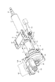
図1は本発明の実施例1のステアリング装置の全体斜視図であり、コラムアシスト型ラックピニオン式パワーステアリング装置である。図1に示すコラムアシスト型ラックピニオン式パワーステアリング装置は、ステアリングホイール101の操作力を軽減するために、コラム105に取付けた操舵補助部(電動アシスト機構)102の操舵補助力をステアリングシャフトに付与し、中間シャフト106を介して、ラックピニオン式のステアリングギヤ103のラックを往復移動させ、タイロッド104を介して舵輪を操舵する方式のパワーステアリング装置である。
FIG. 1 is an overall perspective view of a steering apparatus according to a first embodiment of the present invention, which is a column assist type rack and pinion type power steering apparatus. The column assist type rack and pinion type power steering apparatus shown in FIG. 1 applies a steering assist force of a steering assist portion (electric assist mechanism) 102 attached to a
図2は本発明の実施例1のステアリング装置の要部を示す斜視図、図3は図2の下面図、図4は図2の縦断面図である。図2から図4に示すように、インナーコラム10の外周には、軸方向に摺動可能にアウターコラム11が嵌合している。アウターコラム11には、ステアリングシャフト12が回転可能に軸支され、ステアリングシャフト12の右端(車体後方側)には、図1のステアリングホイール101が固定されている。本発明の実施例では、アウターコラム11は、アルミダイカスト製の一体成型品であるが、鋼管にディスタンスブラケットを溶接したものであってもよい。また、軽量化を目的として、マグネシウムダイカスト製であってもよい。
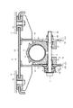
2 is a perspective view showing a main part of the steering device according to the first embodiment of the present invention, FIG. 3 is a bottom view of FIG. 2, and FIG. 4 is a longitudinal sectional view of FIG. As shown in FIGS. 2 to 4, an
アウターコラム11の左側(車体前方側)には、アウターコラム11を左右両側から挟み込むようにして、車体取付けブラケット3が取付けられている。車体取付けブラケット3は、車体41に固定されたアルミ合金製等のカプセル42を介して、車体前方側に離脱可能に取付けられている。
On the left side (front side of the vehicle body) of the
アウターコラム11は、二次衝突時にステアリングホイール101に運転者が衝突して大きな衝撃力が作用すると、カプセル42から車体取付けブラケット3が車体前方側に離脱し、インナーコラム10に案内されて車体前方側にコラプス移動する。このとき、図示しない衝撃エネルギー吸収機構が塑性変形等のエネルギー吸収手段により衝撃エネルギーを吸収する。この衝撃エネルギー吸収手段として、例えば、カプセル42に配置したワイヤやプレートを用い、これを車体取付けブラケット3でしごいて塑性変形させることにより、衝突時の衝撃エネルギーを吸収させる方法等を採用することができる。
In the
インナーコラム10の車体前方側(左側)には、操舵補助部102(電動アシスト機構)のハウジング21の右端が圧入によって固定される。操舵補助部102は、電動モータ23、減速ギヤボックス部24、出力軸25等から構成されている。インナーコラム10は、その下部で直接的に、あるいは、操舵補助部102を介して間接的に、下部車体取付けブラケット22の枢動ピン221によって車体41に対しチルト可能に支持されている。
On the vehicle body front side (left side) of the
操舵補助部102は、ステアリングシャフト12に作用するトルクを検出し、電動モータ23を駆動して、出力軸25を所要の操舵補助力で回転させ、中間シャフト106を経由して、ステアリングギヤ103に連結され、車輪の操舵角を変えることができる。
The
図4に示すように、車体取付けブラケット3は、上板32と、この上板32から下方に延びる側板33、34を有している。上記アウターコラム11には、アウターコラム11の下方に突出して、ディスタンスブラケット13が一体的に形成されている。ディスタンスブラケット13の側面14、15は、車体取付けブラケット3の側板33、34の内側面331、341に摺動可能に接している。
As shown in FIG. 4, the vehicle
車体取付けブラケット3の側板33、34には、チルト調整用長溝35、36が形成されている。チルト調整用長溝35、36は、上記した下部車体取付けブラケット22に設けられた枢動ピン221を中心とする円弧状に形成されている。ディスタンスブラケット13には、図4の左右方向に延びると共に、アウターコラム11の軸心方向に長く延びるテレスコ調整用長溝16、17が形成されている。
Tilt adjusting
丸棒状の締付けロッド5が、上記チルト調整用長溝35、36及びテレスコ調整用長溝16、17を通して、図4の左側から挿入されている。締付けロッド5の左端には円筒状の頭部51が形成されている。締付けロッド5には、頭部51と側板33の外側面332との間に、固定カム52、可動カム53、操作レバー54が、この順で外嵌されている。また、締付けロッド5の右端に形成された雄ねじ56にナット55の内径部に形成された雌ねじ(図示せず)がねじ込まれ、ナット55の左端面が側板34の外側面342に当接している。
The round rod-shaped clamping rod 5 is inserted from the left side of FIG. 4 through the
側板33の外側面332と固定カム52の右端面との間に挟まれて、1枚の抜け止め板6が、テレスコ方向(図4の紙面に直交する方向)に延在して配置されている。抜け止め板6は、インナーコラム10、アウターコラム11の軸心に平行で、その車体前方端がインナーコラム10の車体前方側の端部近傍で、その車体後方端が締付けロッド5の近傍まで延びて配置されている。
A
抜け止め板6は、その車体前方端が、ボルト62によって、ハウジング21の側面に形成された取付座26に固定されている。なお、インナーコラム10の車体前方端に直接取付座を形成し、この取付座に抜け止め板6の車体前方端をボルト止めしてもよい。抜け止め板6には、締付けロッド5が挿通される長溝61が形成され、長溝61は、アウターコラム11のコラプス移動距離L(図2参照)よりも若干長く形成されている。
The front end of the
固定カム52と可動カム53の対向する端面には、相補的な傾斜カム面が形成され、互いに噛み合っている。可動カム53の左側面に連結された操作レバー54を手で操作すると、可動カム53が固定カム52に対して回動する。
Complementary inclined cam surfaces are formed on the opposing end surfaces of the fixed
操作レバー54をクランプ方向に回動すると、固定カム52の傾斜カム面の山に可動カム53の傾斜カム面の山が乗り上げ、締付けロッド5を図4の左側に引っ張ると同時に、固定カム52を図4の右側に押す。
When the operating
抜け止め板6は、固定カム52の右端面によって右側に押され、側板33を内側に変形させ、側板33の内側面331をディスタンスブラケット13の側面14に強く押しつける。同時に、右側のナット55は、側板34を内側に変形させ、側板34の内側面341をディスタンスブラケット13の側面15に強く押しつける。
The retaining
このようにして、抜け止め板6を介して、アウターコラム11のディスタンスブラケット13を、車体取付けブラケット3に強固に締付けることができる。従って、車体取付けブラケット3に対してアウターコラム11が固定され、アウターコラム11のチルト方向の変位及びテレスコ方向の変位が阻止される。
In this way, the
自動車が他の自動車等に衝突し、運転者が慣性でステアリングホイール101に二次衝突すると、アウターコラム11に車体前方側への衝撃力が作用し、締め付けロッド5、チルト調整用長溝35、36を介して、車体取付けブラケット3に衝撃力が伝わる。
When the automobile collides with another automobile or the like and the driver makes a secondary collision with the
この衝撃力によって、車体取付けブラケット3がカプセル42から車体前方側に抜け出し、車体前方側にコラプス移動する。車体取付けブラケット3、アウターコラム11は、締付けロッド5が抜け止め板6の長溝61に案内されて、円滑にコラプス移動する。コラプス移動中に、図示しない衝撃エネルギー吸収機構により衝撃エネルギーが吸収される。
By this impact force, the vehicle
なお、抜け止め板6と固定カム52の右端面との間の摩擦力、及び、抜け止め板6と側板33の外側面332との間の摩擦力も働くため、これによって、追加的に衝突時の衝撃エネルギーを吸収させるようにすることができる。この場合、抜け止め板6は上記摩擦力の耐え、座屈を起こさない充分に剛性をもったものを使用することが必要である。逆に、抜け止め板6によるエネルギー吸収が実質的に行われないように、抜け止め板6を薄い鋼板、非導電性、導電性のいずれでもよいがゴム板、樹脂板等で作り非常に座屈し易くして、上記衝撃エネルギー吸収機構の特性に実質的に影響を及ぼさないようにすることもできる。
The frictional force between the retaining
次に、運転者が操作レバー54を締付解除方向に回動すると、フリーな状態における間隔がディスタンスブラケット13の側面14、15の外側の幅より広く設定された車体取付けブラケット3の側板33、34が、挟持方向と反対の方向へそれぞれ弾性復帰する。
Next, when the driver rotates the
そこで、前記アウターコラム11は、車体取付けブラケット3の側板33、34に対してフリーな状態となる。従って、前記締付けロッド5をチルト調整用長溝35、36に案内させつつチルト方向に変位させたり、前記締付けロッド5に沿って、ディスタンスブラケット13のテレスコ調整用長溝16、17を案内させつつ、アウターコラム11をテレスコ方向に変位させることで、ステアリングホイール101のチルト方向及びテレスコ方向の調整を任意に行うことができる。
Therefore, the
車体取り付けに際し、予め組み立てられたステアリング装置を車体41に取り付けるまでの間に、偶発的に誤って操作レバー54を締付解除方向に回動することが起こりうる。もし、このとき、本願のような抜け止め板6が備えられていないとすると、アウターコラム11は、車体取付けブラケット3の側板33、34、及びインナーコラム10に対してフリーな状態となるため、車体取り付け作業のためにこれを持ち上げようとしたとき、アウターコラム11がインナーコラム10から抜け落ちてしまう可能性がある。そのような場合、冒頭で述べたようにスプラインの位相を合わせるための作業が必要となるので、作業効率が大幅に低下することになる。ところが、本願発明によれば、インナーコラム10からアウターコラム11が抜け出そうとすると、締付けロッド5が抜け止め板6の長溝61の車体後方端の閉鎖端部に引っ掛かるため、インナーコラム10からアウターコラム11が抜け出すことはないので、上のような作業効率の低下を招くことがない。
When attaching the vehicle body, it may happen that the
次に本発明の実施例2について説明する。図5は本発明の実施例2のステアリング装置の要部を示す斜視図であり、実施例1の図2相当図である。以下の説明では、上記実施例と異なる構造部分についてのみ説明し、重複する説明は省略する。また、同一部品には同一番号を付して説明する。 Next, a second embodiment of the present invention will be described. FIG. 5 is a perspective view showing a main part of the steering apparatus according to the second embodiment of the present invention, which corresponds to FIG. In the following description, only structural parts different from the above-described embodiment will be described, and redundant description will be omitted. Further, the same parts will be described with the same numbers.
実施例2は、抜け止め板を複数取り付けて、抜け止め板等による衝突時の衝撃エネルギー吸収性能を向上させた例である。すなわち、図5に示すように、実施例1の抜け止め板6と全く同一形状の抜け止め板6Aを用意し、抜け止め板6Aの車体前方端を、抜け止め板6に重ね合わせ、ボルト62によって、ハウジング21の側面に形成された取付座26に固定する。また、抜け止め板6Aの長溝61に、ワッシャ63を介して締付けロッド5を挿通した後、頭部51と側板33の外側面332との間で、固定カム52、可動カム53、操作レバー54で挟み込む。
The second embodiment is an example in which a plurality of retaining plates are attached to improve impact energy absorption performance at the time of collision by the retaining plates or the like. That is, as shown in FIG. 5, a retaining
このように構成すれば、コラプス移動中に、抜け止め板6と抜け止め板6Aとの間の摩擦力がさらに加わるため、衝突時の衝撃エネルギーをより効果的に吸収することができる。抜け止め板の数をさらに増やせば、衝突時の衝撃エネルギー吸収性能がさらに向上するため好ましい。
If comprised in this way, since the frictional force between the retaining
上記実施例では、抜け止め板を車体取付けブラケットの側板の外側面に配置しているが、車体取付けブラケットの側板の内側面とディスタンスブラケットの側面との間に配置してもよい。また、上記実施例では、抜け止め板を車体取付けブラケットの片側の側板に配置しているが、車体取付けブラケットの両側の側板に配置すれば、衝突時の衝撃エネルギー吸収性能がさらに向上する。場合により、これまで図示しない衝撃エネルギー吸収機構があるとして説明されている元々あった衝撃エネルギー吸収機構を廃し、この抜け止め板によってのみ衝撃エネルギー吸収をさせるようにすることも考えられる。また、チルト/テレスコピック式のステアリング装置に本発明を適用した例について説明したが、テレスコピック位置だけの調整が可能なテレスコピック式のステアリング装置に適用してもよい。 In the above embodiment, the retaining plate is disposed on the outer side surface of the side plate of the vehicle body mounting bracket, but may be disposed between the inner side surface of the side plate of the vehicle body mounting bracket and the side surface of the distance bracket. In the above embodiment, the retaining plate is disposed on the side plate on one side of the vehicle body mounting bracket. However, if it is disposed on the side plates on both sides of the vehicle body mounting bracket, the impact energy absorption performance at the time of collision is further improved. In some cases, it may be considered that the impact energy absorbing mechanism which has been described as having an impact energy absorbing mechanism (not shown) is eliminated and the impact energy is absorbed only by this retaining plate. Further, although an example in which the present invention is applied to a tilt / telescopic steering device has been described, the present invention may be applied to a telescopic steering device capable of adjusting only a telescopic position.
101 ステアリングホイール
102 操舵補助部(電動アシスト機構)
103 ステアリングギヤ
104 タイロッド
105 コラム
106 中間シャフト
10 インナーコラム
11 アウターコラム
12 ステアリングシャフト
13 ディスタンスブラケット
14、15 側面
16、17 テレスコ調整用長溝
21 ハウジング
22 下部車体取付けブラケット
221 枢動ピン
23 電動モータ
24 減速ギヤボックス部
25 出力軸
26 取付座
3 車体取付けブラケット
32 上板
33、34 側板
331、341 内側面
332、342 外側面
35、36 チルト調整用長溝
41 車体
42 カプセル
5 締付けロッド
51 頭部
52 固定カム
53 可動カム
54 操作レバー
55 ナット
56 雄ねじ
6 抜け止め板
6A 抜け止め板
61 長溝
62 ボルト
63 ワッシャ
101
DESCRIPTION OF
Claims (2)
上記インナーコラムの車体後方側に配置され、インナーコラムに軸方向に相対的にテレスコピック移動可能に嵌合され、二次衝突時に車体前方側にコラプス移動可能なアウターコラム、
車体に取付け可能な車体取付けブラケット、
上記車体取付けブラケットの側板を締付け、上記アウターコラムをインナーコラムにテレスコピック移動不能にクランプする締付けロッド、
車体前方端が上記インナーコラムに固定され、インナーコラムの軸心に平行に上記締付けロッド近傍まで延びる抜け止め板、
上記抜け止め板にコラプス移動距離よりも長く形成され、上記締付けロッドが挿通される長溝を有し、
上記車体取付けブラケットの側板に上記抜け止め板の車体後方端が締め付けられていること
を特徴とするステアリング装置。 Inner column that can be attached to the front of the vehicle body,
An outer column disposed on the vehicle body rear side of the inner column, fitted to the inner column so as to be relatively telescopically movable in the axial direction, and collapsible to the vehicle body front side in a secondary collision;
Body mounting bracket that can be mounted on the body,
Tightening rod that clamps the side plate of the vehicle body mounting bracket and clamps the outer column to the inner column so that it cannot telescopically move,
A retaining plate fixed to the inner column at the front end of the vehicle body and extending to the vicinity of the clamping rod in parallel to the axis of the inner column,
The retaining plate is formed longer than the collapse movement distance, and has a long groove through which the clamping rod is inserted,
A steering device, wherein a rear end of a vehicle body of the retaining plate is fastened to a side plate of the vehicle body mounting bracket.
上記抜け止め板が複数重ね合わされていること
を特徴とするステアリング装置。 The steering apparatus according to claim 1, wherein
A steering apparatus, wherein a plurality of the retaining plates are stacked.
Priority Applications (1)
| Application Number | Priority Date | Filing Date | Title |
|---|---|---|---|
| JP2010041628A JP5212403B2 (en) | 2010-02-26 | 2010-02-26 | Steering device |
Applications Claiming Priority (1)
| Application Number | Priority Date | Filing Date | Title |
|---|---|---|---|
| JP2010041628A JP5212403B2 (en) | 2010-02-26 | 2010-02-26 | Steering device |
Publications (2)
| Publication Number | Publication Date |
|---|---|
| JP2011178193A JP2011178193A (en) | 2011-09-15 |
| JP5212403B2 true JP5212403B2 (en) | 2013-06-19 |
Family
ID=44690200
Family Applications (1)
| Application Number | Title | Priority Date | Filing Date |
|---|---|---|---|
| JP2010041628A Expired - Fee Related JP5212403B2 (en) | 2010-02-26 | 2010-02-26 | Steering device |
Country Status (1)
| Country | Link |
|---|---|
| JP (1) | JP5212403B2 (en) |
Families Citing this family (3)
| Publication number | Priority date | Publication date | Assignee | Title |
|---|---|---|---|---|
| JP5998552B2 (en) * | 2012-03-16 | 2016-09-28 | 日本精工株式会社 | Steering column device with telescopic mechanism |
| JP6636798B2 (en) * | 2015-02-27 | 2020-01-29 | 株式会社山田製作所 | Steering device |
| CN109291985B (en) * | 2018-10-08 | 2020-09-22 | 吉利汽车研究院(宁波)有限公司 | Steering column assembly for vehicle and vehicle |
Family Cites Families (2)
| Publication number | Priority date | Publication date | Assignee | Title |
|---|---|---|---|---|
| JP3335485B2 (en) * | 1994-09-13 | 2002-10-15 | 富士機工株式会社 | Vehicle steering column |
| JP2009090737A (en) * | 2007-10-04 | 2009-04-30 | Toyota Motor Corp | Steering column device |
-
2010
- 2010-02-26 JP JP2010041628A patent/JP5212403B2/en not_active Expired - Fee Related
Also Published As
| Publication number | Publication date |
|---|---|
| JP2011178193A (en) | 2011-09-15 |
Similar Documents
| Publication | Publication Date | Title |
|---|---|---|
| US8714047B2 (en) | Steering device | |
| JP5076673B2 (en) | Steering device | |
| JP5293829B2 (en) | Steering device | |
| JP5423722B2 (en) | Steering device | |
| JP5293643B2 (en) | Steering device | |
| JP5737297B2 (en) | Steering device | |
| JP5212403B2 (en) | Steering device | |
| JP5233150B2 (en) | Steering device | |
| JP5218255B2 (en) | Steering device | |
| JP5392189B2 (en) | Steering device | |
| JP4635772B2 (en) | Steering device | |
| JP5316472B2 (en) | Steering device | |
| JP6020206B2 (en) | Shock absorbing steering device | |
| JP4586658B2 (en) | Steering device | |
| US8955882B2 (en) | Steering apparatus | |
| JP5626045B2 (en) | Steering device | |
| JP5664499B2 (en) | Steering device | |
| JP5692252B2 (en) | Steering device | |
| JP5692251B2 (en) | Steering device | |
| JP2012006550A (en) | Impact-absorbing type steering device | |
| JP5691880B2 (en) | Shock absorbing steering device | |
| JP5692250B2 (en) | Steering device | |
| JP5413526B2 (en) | Steering device | |
| JP5724636B2 (en) | Shock absorbing steering device | |
| JP2014104782A (en) | Support device for steering column |
Legal Events
| Date | Code | Title | Description |
|---|---|---|---|
| A621 | Written request for application examination |
Free format text: JAPANESE INTERMEDIATE CODE: A621 Effective date: 20110803 |
|
| A977 | Report on retrieval |
Free format text: JAPANESE INTERMEDIATE CODE: A971007 Effective date: 20121228 |
|
| TRDD | Decision of grant or rejection written | ||
| A01 | Written decision to grant a patent or to grant a registration (utility model) |
Free format text: JAPANESE INTERMEDIATE CODE: A01 Effective date: 20130129 |
|
| A61 | First payment of annual fees (during grant procedure) |
Free format text: JAPANESE INTERMEDIATE CODE: A61 Effective date: 20130211 |
|
| R150 | Certificate of patent or registration of utility model |
Ref document number: 5212403 Country of ref document: JP Free format text: JAPANESE INTERMEDIATE CODE: R150 Free format text: JAPANESE INTERMEDIATE CODE: R150 |
|
| FPAY | Renewal fee payment (event date is renewal date of database) |
Free format text: PAYMENT UNTIL: 20160308 Year of fee payment: 3 |
|
| LAPS | Cancellation because of no payment of annual fees |