JP5209498B2 - Brake control system - Google Patents
Brake control system Download PDFInfo
- Publication number
- JP5209498B2 JP5209498B2 JP2008549868A JP2008549868A JP5209498B2 JP 5209498 B2 JP5209498 B2 JP 5209498B2 JP 2008549868 A JP2008549868 A JP 2008549868A JP 2008549868 A JP2008549868 A JP 2008549868A JP 5209498 B2 JP5209498 B2 JP 5209498B2
- Authority
- JP
- Japan
- Prior art keywords
- brake
- piston
- hydraulic
- booster
- simulator
- Prior art date
- Legal status (The legal status is an assumption and is not a legal conclusion. Google has not performed a legal analysis and makes no representation as to the accuracy of the status listed.)
- Expired - Fee Related
Links
Images


Classifications
-
- B—PERFORMING OPERATIONS; TRANSPORTING
- B60—VEHICLES IN GENERAL
- B60T—VEHICLE BRAKE CONTROL SYSTEMS OR PARTS THEREOF; BRAKE CONTROL SYSTEMS OR PARTS THEREOF, IN GENERAL; ARRANGEMENT OF BRAKING ELEMENTS ON VEHICLES IN GENERAL; PORTABLE DEVICES FOR PREVENTING UNWANTED MOVEMENT OF VEHICLES; VEHICLE MODIFICATIONS TO FACILITATE COOLING OF BRAKES
- B60T7/00—Brake-action initiating means
- B60T7/02—Brake-action initiating means for personal initiation
- B60T7/04—Brake-action initiating means for personal initiation foot actuated
- B60T7/042—Brake-action initiating means for personal initiation foot actuated by electrical means, e.g. using travel or force sensors
-
- B—PERFORMING OPERATIONS; TRANSPORTING
- B60—VEHICLES IN GENERAL
- B60T—VEHICLE BRAKE CONTROL SYSTEMS OR PARTS THEREOF; BRAKE CONTROL SYSTEMS OR PARTS THEREOF, IN GENERAL; ARRANGEMENT OF BRAKING ELEMENTS ON VEHICLES IN GENERAL; PORTABLE DEVICES FOR PREVENTING UNWANTED MOVEMENT OF VEHICLES; VEHICLE MODIFICATIONS TO FACILITATE COOLING OF BRAKES
- B60T13/00—Transmitting braking action from initiating means to ultimate brake actuator with power assistance or drive; Brake systems incorporating such transmitting means, e.g. air-pressure brake systems
- B60T13/10—Transmitting braking action from initiating means to ultimate brake actuator with power assistance or drive; Brake systems incorporating such transmitting means, e.g. air-pressure brake systems with fluid assistance, drive, or release
- B60T13/24—Transmitting braking action from initiating means to ultimate brake actuator with power assistance or drive; Brake systems incorporating such transmitting means, e.g. air-pressure brake systems with fluid assistance, drive, or release the fluid being gaseous
- B60T13/46—Vacuum systems
- B60T13/52—Vacuum systems indirect, i.e. vacuum booster units
- B60T13/57—Vacuum systems indirect, i.e. vacuum booster units characterised by constructional features of control valves
-
- B—PERFORMING OPERATIONS; TRANSPORTING
- B60—VEHICLES IN GENERAL
- B60T—VEHICLE BRAKE CONTROL SYSTEMS OR PARTS THEREOF; BRAKE CONTROL SYSTEMS OR PARTS THEREOF, IN GENERAL; ARRANGEMENT OF BRAKING ELEMENTS ON VEHICLES IN GENERAL; PORTABLE DEVICES FOR PREVENTING UNWANTED MOVEMENT OF VEHICLES; VEHICLE MODIFICATIONS TO FACILITATE COOLING OF BRAKES
- B60T8/00—Arrangements for adjusting wheel-braking force to meet varying vehicular or ground-surface conditions, e.g. limiting or varying distribution of braking force
- B60T8/32—Arrangements for adjusting wheel-braking force to meet varying vehicular or ground-surface conditions, e.g. limiting or varying distribution of braking force responsive to a speed condition, e.g. acceleration or deceleration
- B60T8/34—Arrangements for adjusting wheel-braking force to meet varying vehicular or ground-surface conditions, e.g. limiting or varying distribution of braking force responsive to a speed condition, e.g. acceleration or deceleration having a fluid pressure regulator responsive to a speed condition
- B60T8/44—Arrangements for adjusting wheel-braking force to meet varying vehicular or ground-surface conditions, e.g. limiting or varying distribution of braking force responsive to a speed condition, e.g. acceleration or deceleration having a fluid pressure regulator responsive to a speed condition co-operating with a power-assist booster means associated with a master cylinder for controlling the release and reapplication of brake pressure through an interaction with the power assist device, i.e. open systems
- B60T8/444—Arrangements for adjusting wheel-braking force to meet varying vehicular or ground-surface conditions, e.g. limiting or varying distribution of braking force responsive to a speed condition, e.g. acceleration or deceleration having a fluid pressure regulator responsive to a speed condition co-operating with a power-assist booster means associated with a master cylinder for controlling the release and reapplication of brake pressure through an interaction with the power assist device, i.e. open systems using vacuum
-
- B—PERFORMING OPERATIONS; TRANSPORTING
- B60—VEHICLES IN GENERAL
- B60T—VEHICLE BRAKE CONTROL SYSTEMS OR PARTS THEREOF; BRAKE CONTROL SYSTEMS OR PARTS THEREOF, IN GENERAL; ARRANGEMENT OF BRAKING ELEMENTS ON VEHICLES IN GENERAL; PORTABLE DEVICES FOR PREVENTING UNWANTED MOVEMENT OF VEHICLES; VEHICLE MODIFICATIONS TO FACILITATE COOLING OF BRAKES
- B60T2220/00—Monitoring, detecting driver behaviour; Signalling thereof; Counteracting thereof
- B60T2220/04—Pedal travel sensor, stroke sensor; Sensing brake request
Landscapes
- Engineering & Computer Science (AREA)
- Transportation (AREA)
- Mechanical Engineering (AREA)
- Physics & Mathematics (AREA)
- Fluid Mechanics (AREA)
- Regulating Braking Force (AREA)
- Braking Systems And Boosters (AREA)
Description
本発明は、自動車用のブレーキ制御システム、特に、液圧制御システムに関する。本発明は、また、液圧作動型ブレーキシステムと、電気推進モータ又は発電装置としてのモータを使用する電気ブレーキシステムとを備える、ハイブリット車(電気により推進され且つ内燃機関を使用して推進される車)内に設けられるもののような、ハイブリットブレーキシステムにも適用される。 The present invention relates to a brake control system for an automobile, and more particularly to a hydraulic control system. The present invention also includes a hybrid vehicle (electrically propelled and propelled using an internal combustion engine) comprising a hydraulically actuated brake system and an electric brake system using an electric propulsion motor or a motor as a power generator. It is also applied to a hybrid brake system such as that provided in a car).
先行技術の自動車用の液圧ブレーキシステムにおいて、ブレーキブースタは、実質的に、ピストンに固定された、可動膜により分離された2つの室(前部室すなわち真空室と、後部室すなわち作用室)から成る空間を備えている。制御ロッドは、車の運転者がブレーキペダルを操作したとき、車の前方に向けて動くことができる。この制御ロッドの動きは、ブースト手段及びブースタピストンを作動させるプランジャに伝達される。一般に、これらのブースト手段は、3方弁を備えており、該3方弁の作動は、ブースタの真空室と作用室との間の連通を遮断し且つ、作用室を周囲雰囲気と接続することができる。真空室が通常、真空圧下にあり、また、2つの室の間の圧力差のため、ブースト力が2つの室を分離するピストンに加えられる。このため、ピストンは、前方に動いて、ブレーキ回路のマスタシリンダを作動させる働きをするプッシュロッドに作用する。 In prior art hydraulic brake systems for automobiles, the brake booster consists essentially of two chambers (front chamber or vacuum chamber and rear chamber or working chamber) fixed to the piston and separated by a movable membrane. It is equipped with a space. The control rod can move toward the front of the vehicle when the driver of the vehicle operates the brake pedal. This movement of the control rod is transmitted to the boosting means and the plunger which operates the booster piston. In general, these boosting means comprise a three-way valve, the operation of which cuts off the communication between the vacuum chamber and the working chamber of the booster and connects the working chamber to the ambient atmosphere. Can do. The vacuum chamber is typically under vacuum pressure, and because of the pressure difference between the two chambers, boost force is applied to the piston that separates the two chambers. For this reason, the piston moves forward and acts on a push rod that serves to actuate the master cylinder of the brake circuit.
ブレーキペダルにより作動される制御ロッドは、ブースタのピストンと接触している一方、該ブースタは、マスタシリンダのピストンに作用するプッシュロッドと接触している。このため、ブレーキペダルをマスタシリンダのピストンに結合する色々な部品は、互いに接触している。このため、運転者は、ブレーキペダルを通してブレーキ回路の反動を感触する。 The control rod actuated by the brake pedal is in contact with the booster piston, while the booster is in contact with the push rod acting on the master cylinder piston. For this reason, the various components that couple the brake pedal to the piston of the master cylinder are in contact with each other. For this reason, the driver feels the reaction of the brake circuit through the brake pedal.
しかし、車の装置がブレーキ流体の一部をブレーキ回路内のある箇所からマスタシリンダに向けて変位させたとき、ブレーキペダルに反動が生じ、この反動は、運転者により感触されるであろう。例えば、車の車輪をロックする傾向を有するであろうブレーキ力のとき、アンチロックブレーキシステム(ABS)は、ブレーキ力を小さくする働きをし、また、これを行なうため、ブレーキ流体を車輪シリンダから吸引してそれをマスタシリンダ内に噴射するという働きをする。これと代替的に、動的走行制御を行なう電子安定化プログラム(ESP)において、液圧装置は、ブレーキ命令と独立的に、1つ以上のブレーキ回路に作用することができ、この動作は、また、ブレーキペダルにて感触され、ESPがカットするとき、運転者がブレーキを掛けているならば、運転者は、自分が慣れた感触に必ずしも相応しないブレーキの感触の変化を経験するであろう。 However, when the car device displaces a portion of the brake fluid from a point in the brake circuit toward the master cylinder, a reaction occurs in the brake pedal, which will be felt by the driver. For example, when the braking force will tend to lock the wheels of a car, the anti-lock braking system (ABS) serves to reduce the braking force and to do this, brake fluid is removed from the wheel cylinders. It works to suck and inject it into the master cylinder. Alternatively, in an electronic stabilization program (ESP) that provides dynamic cruise control, the hydraulic device can act on one or more brake circuits, independent of the brake command, Also, if the driver is braking when touched by the brake pedal and the ESP cuts, the driver will experience a change in brake feel that does not necessarily correspond to the feeling that he is used to. .
ブレーキ流体をブレーキ回路中に噴射する液圧装置の効果は、マスタシリンダのピストンを後退させることであるから、この効果は、ブレーキペダルを後退させる効果も有することを指摘すべきである。運転者が比較的大きいブレーキ力を作用させるその瞬間にて、この効果が生じる場合、ブレーキペダルの後退する動きは、運転者のくるぶしにより吸収され、このことは、最小のときでさえ、運転者にとって不快となることが判明している。更に、マスタシリンダピストンの後退する動きは、事故時、特に、運転者がブレーキペダルに強い圧力を加えている間に前面衝突が生ずるとき、身体を損傷させることさえある(例えば、運転者のくるぶしを骨折させることもある)。 It should be pointed out that this effect also has the effect of retracting the brake pedal, since the effect of the hydraulic device that injects the brake fluid into the brake circuit is to retract the piston of the master cylinder. If this effect occurs at the moment when the driver applies a relatively large braking force, the backward movement of the brake pedal is absorbed by the driver's ankle, which is even at a minimum It has been found to be uncomfortable for people. Furthermore, the backward movement of the master cylinder piston can even damage the body in an accident, especially when a frontal collision occurs while the driver is applying high pressure to the brake pedal (eg, the driver's ankle). May be broken).
このため、ブレーキ回路及び(又は)マスタシリンダ内にて生じるこれら効果の全てをブレーキペダルへ向けて前方へ伝達する量は(解消され又は吸収されないにしても)、減少するようにすることが有益であることが判明している。 For this reason, it is beneficial to reduce the amount of all these effects that occur in the brake circuit and / or the master cylinder, which is transmitted forward to the brake pedal (even if not eliminated or absorbed). It has been found that
これらの不利益な点を解決する1つの方法は、制御システムの電気的制御を実現し、また、同一のブレーキ掛け状態下にて、運転者が従来のブレーキシステムによる感触に慣れたブレーキの感触を模擬するブレーキペダルの機械的命令を与えるシステムを提供することである。本明細書の他の部分にて、この装置は、「ブレーキ感触シミュレータ」と称される。このため、このようなシステムにおいて、実際のブレーキ装置は、ブレーキ掛けに応答してブレーキペダルに効果を及ぼすブレーキ感触シミュレータから切り離されている。 One way to overcome these disadvantages is to achieve electrical control of the control system, and the brake feel that the driver is accustomed to feel with a conventional brake system under the same braking conditions. A system for providing a mechanical command of a brake pedal that simulates In other parts of the specification, this device is referred to as a “brake feel simulator”. For this reason, in such a system, the actual braking device is separated from the brake feel simulator that has an effect on the brake pedal in response to braking.
しかし、かかるシステムは、従来の液圧ブレーキシステムと比較して高価である。電気的制御及び接続を導入することは、一般に、信頼性に関する問題を招来する。このため、これらのシステムは、従来の液圧システムと同一の信頼性及び安全性の要件が課される場合、より一層、高価となる。 However, such a system is expensive compared to conventional hydraulic brake systems. Introducing electrical control and connections generally leads to reliability issues. This makes these systems even more expensive when the same reliability and safety requirements are imposed as conventional hydraulic systems.
更に、車を推進させるためバッテリにより作動される電気推進モータと、内燃機関(ガソリン、ディーゼル油、ガス又は任意のその他の燃料にて運転する)の双方を有する、いわゆるハイブリット車は、一般に、電気ブレーキが設けられており、この電気ブレーキにおいて、車の電気推進モータからのエネルギを回収することにより誘導型ブレーキによるブレーキ力が得られる。このとき、電気推進モータは、発電装置として作用し、回収された電気エネルギは、バッテリを再充電するため使用され、このことは、車を使用するときに、有益なことである。 In addition, so-called hybrid vehicles that have both a battery-powered electric propulsion motor to propel the vehicle and an internal combustion engine (operating with gasoline, diesel oil, gas or any other fuel) are generally electric. A brake is provided, and in this electric brake, the braking force by the induction brake can be obtained by recovering energy from the electric propulsion motor of the vehicle. At this time, the electric propulsion motor acts as a power generator and the recovered electrical energy is used to recharge the battery, which is beneficial when using the car.
これらのシステムにおいて、電気ブレーキ力のトルクを変化させることも可能である。このため、ブレーキ掛けのとき、最大量の電気ブレーキの力が常に加えられるとは限らない。このことは、例えば、道路の状態に関する情報を提供するレーダが使用されるとき、又は、ブレーキペダルを多少、急速に操作するとき(例えば、強くブレーキを掛け、次に、ブレーキペダルを離すとき)のような場合である。 In these systems, it is also possible to vary the torque of the electric brake force. For this reason, when the brake is applied, the maximum amount of electric brake force is not always applied. This may be the case, for example, when radar is used to provide information about road conditions, or when the brake pedal is operated somewhat rapidly (eg when braking hard and then releasing the brake pedal). This is the case.
また、安全上の理由、又は、ブレーキペダルの感触と関係した理由のいずれれかのため、逆電流が電気モータに伝達されるような構成とすることもできよう。
しかし、電気ブレーキは、完全に満足し得るものとは限らない。図1には、このブレーキシステムのような電気ブレーキシステムのブレーキ力曲線(時間の関数としてのブレーキトルク)のみが連続線で概略図的に示されている。このグラフは、破線にて、車の速度も示す。第一のブレーキ領域Aにおいて、ブレーキ力は、第二のブレーキ領域B内にて最大の効果に達する迄、漸進的に増大し、その後、第三の領域C内にて車速度が遅くなると、ブレーキトルクは、減少し、第四の領域D内にて実際的に、存在しなくなる。領域A内にて、ブレーキ力は、迅速に完全に効果的にならず、また、領域C及びDにおいて、車が低速度であるとき、ブレーキ力の効果は減少するから、このようなブレーキシステムは、不完全である。このような作動は、図1にて、破線の曲線にて示されている。
It could also be configured such that the reverse current is transmitted to the electric motor, either for safety reasons or for reasons related to the feel of the brake pedal.
However, electric brakes are not always completely satisfactory. In FIG. 1, only the braking force curve (brake torque as a function of time) of an electric brake system such as this brake system is shown schematically in a continuous line. This graph also shows the speed of the car in broken lines. In the first brake region A, the braking force gradually increases until the maximum effect is reached in the second brake region B, and then when the vehicle speed decreases in the third region C, The brake torque decreases and practically does not exist in the fourth region D. In area A, the braking force is not quickly and completely effective, and in areas C and D, when the vehicle is at low speed, the effect of the braking force is reduced. Is incomplete. Such an operation is indicated by a dashed curve in FIG.
回生(recuperative)電気ブレーキのこの不利益な点を解消するため、液圧ブレーキシステムは、領域A、C及びD内にて補充的なブレーキ力を提供する必要がある。 In order to eliminate this disadvantage of regenerative electric brakes, the hydraulic brake system needs to provide supplementary braking force in areas A, C and D.
図2には、電気ブレーキシステム及び液圧ブレーキシステムの作動曲線が示されている。
曲線C1は、図1のものに相応する回生電気ブレーキ力曲線である。例えば、0.7gの車の減速が望まれ、また、電気ブレーキシステムが0.3gの最大減速を実現することができるとき、液圧ブレーキシステムにより与えられるブレーキ力曲線は、曲線C2により概略図で示したものとなる必要がある。領域Aにおいて、液圧ブレーキトルクは、可能な限り迅速に0.7gの減速を実現し、また、次に、電気ブレーキのトルクがその最大値に達し、この電気ブレーキのトルクに起因する等価的減速が0.3gとなる迄、減少する。このようにして、その瞬間に、電気及び液圧ブレーキシステムにより加えられたトルクの合計値が0.7gの減速を提供する。領域B内にて、液圧ブレーキシステムは、0.7gの減速を得るため、電気ブレーキシステムを補充する。その後、領域C内にて、液圧システムのブレーキトルクは、増大して、再度、電気ブレーキシステムに対し補充的なブレーキ力を提供し、また、領域D1において、電気ブレーキトルクが実際に存在しない状態を修復する。
FIG. 2 shows the operating curves of the electric brake system and the hydraulic brake system.
Curve C1 is a regenerative electric brake force curve corresponding to that of FIG. For example, when a 0.7g vehicle deceleration is desired and the electric brake system can achieve a maximum deceleration of 0.3g, the braking force curve provided by the hydraulic brake system is schematically illustrated by curve C2. It must be the one shown in. In region A, the hydraulic brake torque achieves a reduction of 0.7 g as quickly as possible, and then the electric brake torque reaches its maximum value and is equivalent to this electric brake torque. Decrease until deceleration is 0.3g. In this way, at that moment, the total torque applied by the electric and hydraulic brake system provides a reduction of 0.7 g. Within region B, the hydraulic brake system replenishes the electric brake system to obtain a deceleration of 0.7 g. Thereafter, within region C, the brake torque of the hydraulic system increases, again providing supplemental braking force to the electric brake system, and there is actually no electric brake torque in region D1. Repair the condition.
更に、回生ブレーキ回路に加わる荷重は変化するであろうから、回生電気ブレーキシステムの応答時間を無視すれば、このシステムは、常に、同一の態様にて応答することができるとは限らない。このことは、回生回路が実質的に、車のバッテリを含むとき、特に真である。かかる場合、荷重は、バッテリの状態に従って変化するであろう。 Furthermore, since the load applied to the regenerative brake circuit will change, this system may not always respond in the same manner if the response time of the regenerative electric brake system is ignored. This is particularly true when the regenerative circuit substantially includes a car battery. In such a case, the load will vary according to the state of the battery.
かかるシステムにおいて、例えば、コンピュータのような制御回路がブレーキシステムの作動を管理しなければならない。このコンピュータは、ブレーキ掛け動作毎に、作動することが要求される。電気制御システムは、故障し易いことが判明している一方、ブレーキブースタを使用する液圧制御システムは、電気制御システムよりも確実で且つ経済的であることが判明している。 In such a system, a control circuit such as a computer must manage the operation of the brake system. This computer is required to operate every braking operation. While electrical control systems have been found to be prone to failure, hydraulic control systems using brake boosters have been found to be more reliable and economical than electrical control systems.
このため、本発明は、これらの問題点を解決することのできるブレーキシステム、また、望ましくは、車の車輪にブレーキを掛ける装置が液圧により作動されるブレーキシステムに関する。更に、このシステムは、アンチロックブレーキシステム(ABS)又は電子安定化プログラム(ESP)のような色々な車のシステムにより、車のブレーキ回路中にて生じる効果からブレーキペダルを切り離すことができるが、ブレーキペダルに対してブレーキ力の感触を模擬する効果を伝達することができる。 Therefore, the present invention relates to a brake system capable of solving these problems, and preferably to a brake system in which a device for braking a vehicle wheel is operated by hydraulic pressure. In addition, this system allows the brake pedal to be decoupled from the effects produced in the car brake circuit by various car systems such as the anti-lock brake system (ABS) or the electronic stabilization program (ESP), The effect of simulating the feel of the braking force can be transmitted to the brake pedal.
このため、本発明は、自動車用のブレーキ制御システムであって、
ブレーキペダルと、
ピストンによって分離された前部室及び後部室を有して、上記2つの室の間の圧力差に依存する増幅したブレーキ命令を供給するブレーキブースタと、
増幅されたブレーキ命令をブレーキブースタから受け取るブレーキマスタシリンダとを備える上記のブレーキ制御システムに関する。
Therefore, the present invention is a brake control system for automobiles,
Brake pedal,
A brake booster having a front chamber and a rear chamber separated by a piston to supply an amplified brake command depending on the pressure difference between the two chambers;
The present invention relates to a brake control system comprising a brake master cylinder for receiving an amplified brake command from a brake booster.
本発明に従い、ブレーキシステムは、望ましくは、主として通常の作動中(すなわち、故障がないとき)、ブレーキブースタのピストンに機械的に結合されないシミュレータを備えるようにする。このシミュレータは、少なくとも1つのブレーキ命令をブレーキペダルから受け取る一方、ブレーキブースタの前部室と後部室との間の圧力差を確立し又は制御して、ブースタピストンの動きを制御すること意図する。望ましくは、シミュレータは、空圧シミュレータであるようにする。 In accordance with the present invention, the brake system desirably includes a simulator that is not mechanically coupled to the brake booster piston primarily during normal operation (ie, when there is no failure). This simulator is intended to control the movement of the booster piston by receiving or receiving at least one brake command from the brake pedal while establishing or controlling the pressure difference between the front and rear chambers of the brake booster. Desirably, the simulator is a pneumatic simulator.
本発明の1つの好ましい実施の形態に従い、上記ブレーキブースタは、ブースタピストンに固定された3方弁を具備するピストンを有しない。
このように、本発明に従い、3方弁は固定される、すなわち、3方弁は、制御ロッドと、空圧型ピストンと、プッシュロッドとから成る可動部品により機械的に駆動されない。
According to one preferred embodiment of the present invention, the brake booster does not have a piston with a three-way valve fixed to the booster piston.
Thus, according to the present invention, the three-way valve is fixed, i.e., the three-way valve is not mechanically driven by the moving parts consisting of the control rod, pneumatic piston and push rod.
本発明に従った装置は、空圧ブレーキブースタの静止部品に直接又は間接的に固定された支持手段を備えている。
3方制御弁の液圧ピストンには、2つの対向する動作、すなわち第一に、液圧シミュレータからのブレーキ命令と、第二に、好ましくは、上記液圧ピストンと、空圧及び(又は)液圧ブレーキブースタ内への空気又は液体の侵入を感知するセンサとの間にて規制された弾性要素によって加えられた反動力とが加えられる。
The device according to the invention comprises support means fixed directly or indirectly to the stationary part of the pneumatic brake booster.
The hydraulic piston of the three-way control valve has two opposing actions: first, a brake command from the hydraulic simulator, and second, preferably the hydraulic piston, pneumatic and / or The reaction force applied by the elastic element regulated between the sensor for detecting the intrusion of air or liquid into the hydraulic brake booster is applied.
この場合、ブレーキ力を模擬する力をブレーキペダルまで伝達することができるように上記弾性的なブレーキ力の模擬要素の弾性が設定されるようにする構成とされることが好ましい。 In this case, it is preferable that the elasticity of the elastic brake force simulating element is set so that the force simulating the brake force can be transmitted to the brake pedal.
本発明の1つの好ましい実施の形態において、上記弾性的なブレーキ力の模擬要素はばねである。
更に、上記液圧シミュレータは、次のことを行なうことができる3方弁を備えるような構成とすることができる、すなわち、
後部室を前部室と連通する状態に置くこと、
又は後部室を前部室から隔離すること、
又は後部室を前部室と後部室との間の圧力差を確立する、圧力源と連通する状態に置くことができる。
In one preferred embodiment of the present invention, the elastic braking force simulation element is a spring.
Furthermore, the hydraulic simulator can be configured to include a three-way valve that can perform the following:
Placing the rear chamber in communication with the front chamber,
Or isolating the rear chamber from the front chamber,
Alternatively, the rear chamber can be placed in communication with a pressure source that establishes a pressure difference between the front chamber and the rear chamber.
また、望ましくは、第一に、マスタシリンダの内部及び(又は)車の液圧回路の任意の箇所の間、また、第二に、液圧シミュレータとの間の液圧接続部が存在し、マスタシリンダ及び(又は)上記液圧回路内の圧力の変化に相応する力をブレーキペダルまで伝達することができるようにする。 Preferably, first, there is a hydraulic connection between the interior of the master cylinder and / or any part of the hydraulic circuit of the vehicle, and secondly, with the hydraulic simulator, A force corresponding to a change in pressure in the master cylinder and / or the hydraulic circuit can be transmitted to the brake pedal.
3方弁に関して、3方弁が上記制御ピストンの作動の下、動くことができるセンサと、センサの動作の下、動くことができる弁シャッタと、弁シャッタが軸受けすることのできる固定の弁座とを備えるような構成とすることができる。 With regard to a three-way valve, a sensor that allows the three-way valve to move under the operation of the control piston, a valve shutter that can move under the action of the sensor, and a fixed valve seat that the valve shutter can bear. It can be set as the structure provided with these.
本発明の1つの代替的な形態に従い、システムは、ブレーキペダルにより制御され、また、液圧回路内にて圧力を発生させることによりブレーキ力を生じさせ、液圧シミュレータの制御ピストンの動きを制御する中間の液圧制御装置を備えている。 In accordance with one alternative form of the invention, the system is controlled by a brake pedal and also generates a braking force by generating pressure in the hydraulic circuit to control the movement of the control piston of the hydraulic simulator. An intermediate hydraulic pressure control device is provided.
また、ブレーキペダルが制御ピストンに直接作用して、その動きを制御するような構成とすることもできる。
本発明のシステムの別の代替的な実施の形態に従い、中間の液圧制御装置は、固定され又はブレーキブースタ内に組み込まれる。更に、該液圧制御装置は、ブレーキブースタの軸線に沿って配置された制御ロッドを備えている。この制御ロッドは、ブレーキペダルにより制御され且つ、特に、故障時及び(又は)ブレーキペダルを急速に操作したとき、ブレーキブースタピストンを直接又は間接的に押すことができる。
Moreover, it can also be set as the structure which a brake pedal acts on a control piston directly, and controls the movement.
In accordance with another alternative embodiment of the system of the present invention, the intermediate hydraulic control device is fixed or incorporated into the brake booster. Further, the hydraulic pressure control device includes a control rod disposed along the axis of the brake booster. The control rod is controlled by the brake pedal and can push the brake booster piston directly or indirectly, especially in the event of a failure and / or when the brake pedal is operated rapidly.
本発明のシステムの別の代替的な実施の形態に従い、上記液圧シミュレータは、3方弁の1つのポートが前部室と連通し、別のポートが後部室と連通するような態様にて固定され又はブースタ内に組み込まれる。 In accordance with another alternative embodiment of the system of the present invention, the hydraulic simulator is fixed in such a manner that one port of the three-way valve communicates with the front chamber and another port communicates with the rear chamber. Or incorporated in a booster.
次に、望ましくは、上記液圧シミュレータがブレーキブースタ内の軸線に沿って配置されるような構成とすることもできる。
上記制御ピストンは、ブレーキペダルに機械的に結合されるような構成とすることも可能である。
Next, preferably, the hydraulic pressure simulator may be arranged along an axis in the brake booster.
The control piston may be configured to be mechanically coupled to the brake pedal.
望ましくは、液圧シミュレータは、ブレーキペダルの制御の下、軸方向に動き且つ、ブースタピストンの動きを制御することができるようにする。
別の代替的な実施の形態に従い、液圧シミュレータは、センサの移動軸線を有する。上記軸線は、ブースタピストン又は加圧ロッドを軸方向に押して、マスタシリンダピストンの動きを制御することができる。
Desirably, the hydraulic simulator moves axially under the control of the brake pedal and allows the booster piston movement to be controlled.
According to another alternative embodiment, the hydraulic simulator has a movement axis of the sensor. The axis can push the booster piston or pressure rod in the axial direction to control the movement of the master cylinder piston.
また、望ましくは、上記制御ピストンが流体を充填した空間内にて動くような構成とすることもできる。
また、上記制御ピストンは、ブレーキ流体が供給される空間内にて弁を介して、車のブレーキ流体リザーバから動くようにすることもできる。
Desirably, the control piston can be moved in a space filled with fluid.
The control piston may be moved from a brake fluid reservoir of the vehicle via a valve in a space to which the brake fluid is supplied.
上記空間はまた、上記弾性要素を保持することもできる。 The space can also hold the elastic element.
本発明の色々な目的及び特徴は、添付図面に関して単に一例として掲げた以下の説明からより明確に明らかになるであろう。
本発明に従ったブレーキシステムの全体として一例としての実施の形態について、先ず、図3を参照して説明する。
Various objects and features of the present invention will become more apparent from the following description, given by way of example only with reference to the accompanying drawings.
An embodiment as an example of the brake system according to the present invention will be described first with reference to FIG.
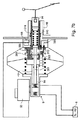
このシステムは、それ自体既知の態様にて、ブレーキブースタ4を備えており、該ブレーキブースタは、ブースタ4の軸線に沿って動くことができるブレーキサーボ膜又はピストン42により分離された作用室41と、真空室40とを含む。プッシュロッド43を介するピストン42の動きは、ブレーキマスタシリンダ5のピストンの動きを制御する。このマスタシリンダは、車のブレーキ回路6内に圧力を誘発する。
This system comprises, in a manner known per se, a brake booster 4, which has a working
本発明に従い、本明細書の以下の部分にて、液圧シミュレータ3と称する中間の液圧装置がある。車の運転者により操作されるブレーキ制御装置又はブレーキペダル1は、液圧シミュレータ3を制御する。液圧シミュレータは、管32により作用室41と接続され、また、管33により真空室と接続された3方弁30を備えることが理解される。この弁は、次のことを行なうことができる、すなわち、
管32、33を互いに連通させることにより、作用室41を真空室40と連通する状態に置くこと。この場合、ピストン42の両側部をわたる圧力は、実質的に均衡し、このピストンは不可動のままである。
In accordance with the present invention, there is an intermediate hydraulic device referred to as a hydraulic simulator 3 in the remainder of this specification. A brake control device or a
Place the working
又は、作用室41を真空室40から隔離すること(これは、ブレーキ段階の開始時である)、
又は、管32を管33から隔離し且つ、該管を雰囲気の空気と接続することにより、作用室41を雰囲気の空気と連通する状態に置くことができる。真空室40と作用室41との間に圧力差が形成される。ピストン42は、真空室に向けて(図3の左方向)に動くよう付勢される。ピストン42の動きは、プッシュロッド43をブレーキマスタシリンダ5に向けて押す効果を有する。このため、ブースタは、ブレーキマスタシリンダに対しブレーキ力を供給する。
Or isolating the working
Alternatively, the working
このようなシステムにおいて、このため、ブレーキペダルは、車のブレーキブースタ4、ブレーキマスタシリンダ5及び液圧ブレーキ回路6から機械的に非結合状態とされる。
これに反して、液圧シミュレータ3を車の液圧回路、特に、管62を介してマスタシリンダの1つの室と接続するような構成とすることもできる。かかる状態下にて、ブレーキペダルが何ら変化せず、また、車の液圧回路内の圧力が変化しないとき、マスタシリンダへのブレーキ流体を少なくとも部分的に液圧シミュレータ3に移送することができ、これらが変化したとき、該液圧シミュレータは、ロッド34を介してブレーキペダルに伝達される。これらのブレーキ流体の移動は、例えば、アンチロックブレーキシステム(ABS)又は電子安定化プログラム(ESP)により誘発させることができる。
In such a system, the brake pedal is thus mechanically disconnected from the vehicle brake booster 4, the brake master cylinder 5 and the hydraulic brake circuit 6.
On the other hand, the hydraulic simulator 3 can be configured to be connected to one chamber of the master cylinder via the hydraulic circuit of the vehicle, in particular, the
このため、これらの変化は、ブレーキペダルに向けてフィルタかけし、運転者の快適性を向上させることを可能にすると同時に、ブレーキシステムの状態を一層良く監視することを許容する。 As such, these changes can be filtered towards the brake pedal to improve driver comfort while permitting better monitoring of the condition of the brake system.
更に、液圧シミュレータ3は、ブレーキペダルと3方弁の制御装置との間に弾性要素(図3に図示せず)を備えることができ、該弾性要素は、ブレーキペダルを動かす命令に抵抗する力を与え、これにより運転者にとって利益となるように、加えられたブレーキ力を模擬する効果を有する。 Furthermore, the hydraulic simulator 3 can be provided with an elastic element (not shown in FIG. 3) between the brake pedal and the control device of the three-way valve, which resists the command to move the brake pedal. It has the effect of simulating the applied braking force so as to give power and thereby benefit the driver.
このため、本発明のシステムは、ブレーキブースタ4を制御する3方弁を備えているが、この3方弁は、当該技術に一般に使用されているブレーキサーボ装置における3方弁と異なり、通常のブレーキ掛け状態にて動かない。 For this reason, the system of the present invention includes a three-way valve that controls the brake booster 4, but this three-way valve is different from a three-way valve in a brake servo device generally used in the art, and is a normal one. It does not move when the brake is applied.
更に、マスタシリンダ5の主ピストンは3方弁と接続されていない。
最後に、ブレーキペダルと3方弁の制御装置との間に配置された弾性要素は、ブレーキ回路からの全ての反動がブレーキペダルに直接戻されるのを防止し且つ、ブレーキペダルへのブレーキ力のフィードバックを管理する法則を導入するため、非結合状態とする機能を果たす。
Furthermore, the main piston of the master cylinder 5 is not connected to the three-way valve.
Finally, an elastic element located between the brake pedal and the three-way valve controller prevents all reaction from the brake circuit from being returned directly to the brake pedal and reduces the braking force applied to the brake pedal. In order to introduce a law to manage feedback, it fulfills the function of making it uncoupled.
マスタシリンダの位置は、ブレーキペダルの位置と独立的であり、また、模擬するばねが存在するため、本発明のシステムは、次のことを可能にする、
すなわち、ブレーキ力をブレーキペダルの位置に対して関係付ける法則を確立すること。ブレーキペダルの移動距離、力及びブレーキ回路内の圧力の間の関係は、この場合、通常の作動状況にて常に一定とすることができる。
Since the position of the master cylinder is independent of the position of the brake pedal, and there is a spring to simulate, the system of the present invention enables the following:
That is, establish a law that relates braking force to brake pedal position. In this case, the relationship between the distance traveled by the brake pedal, the force and the pressure in the brake circuit can always be constant under normal operating conditions.
液圧回路からの障害(例えば、ABSシステムが作動しているときに生ずる振動を伴う液圧の脈動)を除去すること、
例えば、大型のブレーキ(大径のブレーキ及び(又は)移動距離が長いブレーキ)におけるブレーキ流体の大きい変位及び吸収時の振動に対する不感受性を実現すること、
車のブレーキとマスタシリンダとの間にて、一方向に又はその反対方向に向けて液圧装置に起因するブレーキ流体の容積の移動に対する不感受性を実現すること(又は感受性を低下させること)である。
Removing disturbances from the hydraulic circuit (eg hydraulic pulsations with vibrations that occur when the ABS system is operating);
For example, to realize insensitivity to large displacement of brake fluid and vibration during absorption in large brakes (large diameter brakes and / or long travel distance brakes),
By realizing (or reducing sensitivity) the movement of the brake fluid volume caused by the hydraulic device in one direction or in the opposite direction between the car brake and the master cylinder is there.
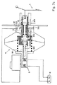
次に、本発明に従ったブレーキシステムの一例としての実施の形態について図4aを参照して、以下により詳細に説明する。図3におけるものと同一の機能を果たす図4aの要素は、同一の参照番号にて表示されている。本明細書に添付したその他の図面に関しても同一である。 An embodiment as an example of a brake system according to the invention will now be described in more detail below with reference to FIG. 4a. Elements of FIG. 4a that perform the same functions as in FIG. 3 are labeled with the same reference numbers. The same applies to other drawings attached to this specification.
このシステムは、
車の運転者によって制御し且つ、液圧制御装置2を作動させるために使用することができるブレーキペダル1と、
ブレーキペダルにより制御されて、室21を加圧し、加圧された流体を管22内に噴射することができるピストン20を備える、液圧制御装置2と、
図3の液圧シミュレータ3に相応する液圧シミュレータ3とを備えている。該液圧シミュレータは、管22内に噴射された圧力を受け取り、また、その位置に依存して、ブレーキブースタ4の作動を制御することができる。この液圧シミュレータの構造及び作動に関して以下により詳細に説明する。
This system
A
A hydraulic control device 2 comprising a
A hydraulic simulator 3 corresponding to the hydraulic simulator 3 of FIG. 3 is provided. The hydraulic simulator receives the pressure injected into the
軸方向に可動のピストン42により互いに分離された真空室40(殆どのブースタにおける前部室)と、作用室41(後部室)とを備える液圧ブレーキブースタ又はブレーキサーボ装置4を備えている。真空源45は、真空室40内に真空圧を形成することを許容する。ピストン42の動き(図4aの左方向)は、プッシュロッド43の動きを引き起し、
その動きがプッシュロッド43により制御される、ピストン50、50´を備えるブレーキマスタシリンダ5と、
ブレーキ圧力を車の車輪のシリンダ装置に伝達することができる液圧ブレーキ回路6とを備えている。
A hydraulic brake booster or brake servo device 4 having a vacuum chamber 40 (a front chamber in most boosters) and a working chamber 41 (a rear chamber) separated from each other by an axially
A brake master cylinder 5 with
And a hydraulic brake circuit 6 capable of transmitting brake pressure to a cylinder device of a vehicle wheel.
液圧シミュレータ3は、液圧制御装置2から達する管22が接続される入口室31を備えている。入口室31は、3方弁30を作動させるピストン34を保持している。
3方弁30は、センサ302(又はピストンプランジャ)を軸受けする軸方向に可動のセンサ主軸301を備えている。このセンサは、入口座部として知られた座部を備え、該入口座部は、その位置に依存して、弁シャッタ303と接触することができる。弁シャッタ303は、その位置に依存して、弁座309と接触することができる。ばね312は、センサを休止状態にて右方向(図面にて)に押し戻すことができ、また、ばね311は、弁シャッタ303を左方向に押すことができる。
The hydraulic pressure simulator 3 includes an
The three-
3方弁30は、次のように接続される、すなわち
1つのポート305により雰囲気圧力に、
1つのポート306及び管33によりブレーキサーボ装置の真空室40に、
ポート307及び管32によりブレーキサーボ装置の作用室41にそれぞれ接続されている。
The three-
The
The
液圧シミュレータ3はまた、ピストン34と可動のセンサ主軸301との間に配置された模擬ばね310も保持している。このばねの目的は、運転者にとって利益となるように、ブレーキ力を模擬し、また、ブレーキペダルの移動距離を決定することである。ばね310の圧縮は、ブレーキペダルが動いて(前進し)、これにより従来のブレーキシステムの振舞いを模擬することを許容する。
The hydraulic simulator 3 also holds a
更に、液圧シミュレータ3は、管62によりブレーキ回路と接続されて、ブレーキ回路内の圧力がセンサ主軸301に作用することを許容する1つのポート308を有している。
Further, the hydraulic pressure simulator 3 has one
ブレーキサーボ装置4は、図3に関して説明した通りである。該ブレーキサーボ装置は、ピストン42及びプッシュロッド43の動きを案内する主軸44を有している。更に、真空源45は、真空室40内にて真空圧が形成され又は圧力が降下することを許容する。
The brake servo device 4 is as described with reference to FIG. The brake servo device has a main shaft 44 that guides the movement of the
ブレーキマスタシリンダ5は、例えば、リザーバ53を介してブレーキ流体が供給されるタンデムマスタシリンダである。
図4aにて、破線で表したブレーキ回路6は、管60、61によりマスタシリンダと接続されている。管62は、管61をシミュレータ3と接続する。
The brake master cylinder 5 is a tandem master cylinder to which brake fluid is supplied via the
In FIG. 4 a, the brake circuit 6 represented by a broken line is connected to the master cylinder by
ブレーキ回路に作用し且つブレーキ回路と接続されたシステムが存在する。これらは、例えば、電子安定化プログラム7(ESP)と、アンチロックブレーキシステム7´(ABS)とである。 There are systems that act on and are connected to the brake circuit. These are, for example, an electronic stabilization program 7 (ESP) and an antilock brake system 7 '(ABS).
図4aのシステムが作用する態様に関して、色々な作動段階にて液圧シミュレータ3の色々な状態を示す図4aから図4dを参照して以下に説明する。
運転者がブレーキペダル1を踏み込まないとき、ブレーキシステムは休止している。液圧シミュレータは図4bに示した状態にある。3方弁30は、管32、33、ポート306、307及び内側ポート304として表した通路を介して作用室41と連通した真空室40を閉じる。2つの室、40、41は、同一の圧力であるため、ブレーキサーボ装置4によりブレーキマスタシリンダ5にブレーキ力は伝達されない。
The manner in which the system of FIG. 4a operates will be described below with reference to FIGS. 4a to 4d showing the various states of the hydraulic simulator 3 in various stages of operation.
When the driver does not depress the
運転者がブレーキペダル1を踏み込むと、液圧制御装置2のピストン20は、室21内に保持された流体(又は気体)を圧縮する。圧力は、管22に沿って液圧シミュレータ3の入口室31に伝達される。この圧力によって、ピストン34は動き、このピストンはばね310を介してセンサ主軸301を加圧する。センサ302は、左方向(図4c)に動く。ばね311により押された弁シャッタ303は、また、左方向にも動き且つポート304を閉じる。ポート306、307の間の連通は閉じられる。真空室40は作用室41から隔離された状態となる。
When the driver steps on the
入口室内の圧力が上昇すると、ピストン34は、左方向に更に動く。センサ主軸301及びセンサ302もまた左方向に動く。図4dにて見ることができるように、センサ302は、弁シャッタ303から動いて離れ且つ、ポート307、305の間の連通ポート313を開く。このため、作用室41は、液圧シミュレータの3方弁を介して雰囲気圧力と連通する状態に置かれる。
As the pressure in the inlet chamber increases, the
作用室41内の圧力は、真空室40内の圧力よりも高圧となる。その結果、ピストン42及びプッシュロッド43は、左方向に駆動される(図4a参照)。プッシュロッド43は、主ピストン50を押して第二のピストン50´の動きを生ずる圧力上昇を引き起こす。マスタシリンダ5は、管60、61内に及びブレーキ回路6内にブレーキ圧力を誘発する。
The pressure in the working
このため、ブレーキペダル1の作動は、ブレーキ命令を液圧シミュレータ3を介してブレーキサーボ装置4に伝達することを許容する。一方、ブレーキサーボ装置4は、車のブレーキ回路内にブレーキ圧力を形成するよう命令している。
For this reason, the operation of the
液圧シミュレータにおいて、ブレーキペダルから送られたブレーキ命令は、ばね310を介して伝達される。このばねの弾性(そのばね率)を設定することは、ブレーキペダルに加わるブレーキ力を模擬することを可能にする。このため、運転者にとって有益であるように、従来のブレーキシステムの反動と同様のブレーキ力に対する反動を模擬することが可能である。
In the hydraulic simulator, the brake command sent from the brake pedal is transmitted via the
更に、特定の車には、車のブレーキ回路に作用することのできるシステムが設けられている。これらは、例えば、アンチロックブレーキシステム7´(ABS)及び電子安定化プログラム7(ESP)である。運転者に対してこれらのシステムが作動しており、車が路面にてその安定性の限界点に達することを注意を促がすことができる感覚を運転者に提供することができることは、有益なことである。 In addition, certain vehicles are provided with a system that can act on the brake circuit of the vehicle. These are, for example, the antilock brake system 7 '(ABS) and the electronic stabilization program 7 (ESP). It would be beneficial to be able to provide the driver with a sense that these systems are operating and that can alert the driver that the car has reached its stability limit on the road surface. It is a thing.
本発明のシステムは、3方弁を均衡させるのみならず、必要である場合、ブレーキペダルにて感触される反動を付与するため、ブレーキ回路の管(例えば、参照番号61)をブレーキシミュレータのポート308と接続する管62を提供する。このポートは、センサ主軸301の一端がその内部にて摺動するシミュレーション室314と連通している。このように、ブレーキ流体の圧力は、センサ主軸301のこの端部に与えられる。このため、この主軸には、ブレーキ回路内にて誘発された圧力の変化が加わり、主軸は、また、これらの変化をブレーキペダルまで伝達する。
The system of the present invention not only balances the three-way valve, but also applies a brake circuit tube (eg, reference numeral 61) to the brake simulator port to provide a reaction felt by the brake pedal if necessary. A
このため、このようなシステムにおいて、センサは、液圧シミュレータの入口室31内の圧力P1の上昇と、シミュレーション室314内の圧力P2の上昇とを均衡させようとする。
For this reason, in such a system, the sensor tries to balance the increase in the pressure P1 in the
一般に、ブーストされたブレーキシステムにおいて、ブースト比は、次の比によって与えられる。
1/S=P/F
ここで、
Fは、制御ロッドに加えられる力を表わし、
Pは、ブレーキマスタシリンダにより供給されるブレーキ圧力を表わす。
In general, in a boosted brake system, the boost ratio is given by:
1 / S = P / F
here,
F represents the force applied to the control rod,
P represents the brake pressure supplied by the brake master cylinder.
図4aのシステムにおいて、ピストン20の制御ロッドに付与されるブレーキペダルにより与えられたブレーキ力Finは、液圧制御装置の室21及び液圧シミュレータ3の入口室31によって伝達される。
In the system of FIG. 4 a, the braking force Fin applied by the brake pedal applied to the control rod of the
S0は、室21の断面積を表わし、
S1は、入口室31の断面積を表わし、
S2は、シミュレーション室314の断面積を表わし、
この場合、理論的なブースト比は、次の比によって与えられる。
S0 represents the cross-sectional area of the
S1 represents the cross-sectional area of the
S2 represents the cross-sectional area of the
In this case, the theoretical boost ratio is given by:
S1/S0・S2
ピストン20の制御ロッドに与えられる入力力Finは、摩擦を無視すれば、次式によって与えられる(図4a参照)。
S1 / S0 ・ S2
The input force Fin given to the control rod of the
Fin=Ra・Tin・S02/S12
ここで、
Raは、ばね310の剛性(N/mにて表示)、
Tinは、ピストン20の制御ロッドの移動距離、
S0は室21の断面積、
S1は室31の断面積である。
Fin = Ra · Tin · S0 2 / S1 2
here,
Ra is the rigidity of the spring 310 (indicated in N / m),
Tin is the moving distance of the control rod of the
S0 is the cross-sectional area of the
図4aを更に参照し、また、摩擦を無視すれば、ブレーキマスタシリンダ内の圧力Pmcは、ブレーキペダルに加わる力の関数である。この圧力は、次の関係を使用して表わすことができる。 Still referring to FIG. 4a and ignoring friction, the pressure Pmc in the brake master cylinder is a function of the force applied to the brake pedal. This pressure can be expressed using the following relationship:
PMC=[(Ra・Tin・S0/S10−Fv]/S2
ここで、
PMCは、マスタシリンダ5内の圧力、
Raは、模擬するばね310の剛性、
Tinは、ピストン20の制御ロッド(従ってピストン20自体)の移動距離、
S0は室21の断面積、
S1は室31の断面積、
S2は室314の断面積、
Fvは、センサが平衡状態にあるとき、センサばね312に加わる荷重である。
PMC = [(Ra · Tin · S0 / S10-Fv] / S2
here,
PMC is the pressure in the master cylinder 5,
Ra is the rigidity of the
Tin is the distance traveled by the control rod of the piston 20 (and hence the
S0 is the cross-sectional area of the
S1 is the cross-sectional area of the
S2 is the cross-sectional area of the
Fv is a load applied to the
このため、本発明のシステムにおいて、ブレーキペダルと3方弁の制御装置との間に配置された弾性要素は、ブレーキ回路からの反動がブレーキペダルに直接供給して戻されるのを防止すると共に、ブレーキペダルへのブレーキ力のフィードバックを管理する法則を形成する、非結合状態とする機能を果たす。任意の瞬間にて、3方弁は、次の力の均衡によって制御される、すなわち、
ブレーキペダルに加わる力の関数である駆動力、
マスタシリンダ(又は液圧ブレーキ回路内)の圧力である。
For this reason, in the system of the present invention, the elastic element disposed between the brake pedal and the control device for the three-way valve prevents the reaction from the brake circuit from being supplied directly to the brake pedal and returned. Acts as a non-coupled state, forming a law that manages the feedback of braking force to the brake pedal. At any moment, the three-way valve is controlled by the following force balance:
Driving force, which is a function of the force applied to the brake pedal,
This is the pressure in the master cylinder (or in the hydraulic brake circuit).
このため、設計者は、最も適したマスタシリンダ(例えば、大きい容積及び(又は)長い移動距離を有するもの)を自由に選ぶことができる。このようなシステムは、例えば、液圧ブレーキ回路内の空気の存在、この場合、平衡状態を実現し得るように長くされるブレーキペダルの移動距離のような、誤作動を補正することができる。 Thus, the designer is free to choose the most suitable master cylinder (e.g., having a large volume and / or long travel distance). Such a system can correct malfunctions, such as the presence of air in the hydraulic brake circuit, in this case the distance traveled by the brake pedal that is lengthened to achieve equilibrium.
更に、上述したように、3方弁3は、ブレーキブースタ4を制御するため使用することができるが、通常のブレーキ状況のとき、当該技術にて既知のブレーキブースタについて生じるものと相違し、動かない。 Furthermore, as mentioned above, the three-way valve 3 can be used to control the brake booster 4, but in normal braking situations it differs from what occurs for brake boosters known in the art, Absent.
更に、マスタシリンダ5の主ピストンは、3方弁と接続されていない。
図5aには、本発明に従った液圧シミュレータ3の一例としての実施の形態が示されている。この場合にも、次のものが示されている。すなわち、
入力ピストン34、
模擬ばね310
センサ302、
弁シャッタ303、
弁座309、
真空室及び作用室にそれぞれ到るポート306、307及び雰囲気圧力に排気するポート305、
ブレーキ圧力を液圧シミュレータに戻すポート308が示されている。
Furthermore, the main piston of the master cylinder 5 is not connected to the three-way valve.
FIG. 5a shows an embodiment as an example of a hydraulic simulator 3 according to the invention. Again, the following is shown: That is,
A
図5aのシミュレータは、管21、32、33、62を図4aに従って接続することにより、図5bに示したように設定される。
図6には、液圧制御装置2がブレーキサーボ装置4内に組み込まれた、図4aのシステムの1つの実施の形態が示されている。
The simulator of FIG. 5a is set up as shown in FIG. 5b by connecting the
FIG. 6 shows an embodiment of the system of FIG. 4 a in which the hydraulic control device 2 is integrated in the brake servo device 4.
液圧シミュレータ3は、上述したものと同様の態様にて製造される。該シミュレータは、同一の要素を含んでおり、このため、この要素については、再度、
説明しない。
The hydraulic simulator 3 is manufactured in the same manner as described above. The simulator contains the same elements, so for this element again
I do not explain.
液圧制御装置2は、ブレーキサーボ装置4の軸線に沿って配置されている。該液圧制御装置は、作用室41に入る制御ロッド24を有している。この制御ロッドの一端は、ピストン42及びプッシュロッド43から短い距離にある。この設置は、液圧シミュレータ及び(又は)ブレーキサーボ装置が故障したとき、圧力をプッシュロッド43に直接又はほぼ直接的に(ピストン20及び制御ロッド24を介して)与えることができることを意味する。
The hydraulic control device 2 is disposed along the axis of the brake servo device 4. The hydraulic pressure control device has a
制御装置2のピストン20の室21及び液圧シミュレータの入口室31は、車のブレーキ流体とすることのできる流体にて充填することができる。このとき、次に、これらの室には、ブレーキ流体リザーバと接続された弁54を介してブレーキ流体が供給される。ブレーキを掛けていないとき、弁54は開かれ、リザーバからのブレーキ流体は、室21、31に供給される。ブレーキを掛けているとき、弁54は閉じられ、室21、31は、ブレーキ流体リザーバから隔離されている。
The
次に、本発明のシステムの1つの代替的な実施の形態について、図7aを参照して説明する。既に上述したように、その他の図面と同一の機能を果たす、この図7aの要素は、同一の参照番号にて表示されている。 Next, one alternative embodiment of the system of the present invention will be described with reference to FIG. 7a. As already mentioned above, the elements of this FIG. 7a that perform the same functions as in the other figures are labeled with the same reference numerals.
この代替的な実施の形態において、ブレーキシミュレータ3は、ブレーキサーボ装置4内に組み込まれている。更に、センサ302を制御するピストン34は、ブレーキペダルにより直接、制御されるが、本発明の範囲から逸脱せずに、図4aに参照番号2で示したような、制御装置により制御されるようにしてもよい。
In this alternative embodiment, the brake simulator 3 is incorporated in the brake servo device 4. Further, the
液圧シミュレータ3は、この場合にも同様に、模擬ばね310、センサ主軸301、センサ302、弁シャッタ303、弁座309、雰囲気圧力に排気するためのポート305を保持している。真空室40及び作用室41にそれぞれ対するポート306、307のみが異なるように見えるであろうが、液圧シミュレータが作用する態様は、通常の作動状態下にて、図4aにおけるものと同一である。
In this case as well, the hydraulic simulator 3 holds a
休止時、ブレーキ命令が存在しないとき、システムは、図7aに示した状態にある。作用室41は、ポート307及びポート304を介して真空室40と連通する状態に置かれる。
At rest, when there is no brake command, the system is in the state shown in FIG. 7a. The working
運転者がブレーキペダルを踏んだとき、図7bに示したように、次のように作動する。
ピストン34は左方向に動く、
該ピストンは、ばね310を介して左方向にセンサ主軸301まで動かす力を伝達する、
センサ302は、左方向に動き、
弁シャッタ303は、弁座309に対して押し付けられ、
センサ302は、弁シャッタ303から分離し、また、通路313を開いて作用室41がポート305と連通することを許容し、
作用室41は、雰囲気圧力と接続され、
ピストン42は、左方向に動き、
ブレーキ力が左方向にマスタシリンダ5のピストン50に加えられる。図7aに示した有益な一例としての実施の形態において、単一片の部品は、プッシュロッド(図4aのプッシュロッド43)及びピストン50の双方として作用する。
When the driver depresses the brake pedal, as shown in FIG.
The
The piston transmits a force to move to the sensor
The
The
The working
The
The braking force is applied to the
このため、この作動中、液圧シミュレータ3は、制御ロッドがマスタシリンダのピストンを作動させるプッシュロッドと機械的に(間接的にも)接触せずに、ブレーキ力がブレーキサーボ装置からマスタシリンダに伝達されることを許容することが理解できる。このため、ブレーキペダルの制御は、ブレーキサーボ装置及びマスタシリンダから機械的に非結合状態とされている。 For this reason, during this operation, the hydraulic pressure simulator 3 does not mechanically (indirectly) contact the push rod that operates the piston of the master cylinder, and the brake force is applied from the brake servo device to the master cylinder. It can be understood that it is allowed to be transmitted. For this reason, the control of the brake pedal is mechanically disconnected from the brake servo device and the master cylinder.
このため、ブレーキペダルは、ブレーキサーボ装置及びブレーキ回路の作動に起因する効果から少なくとも部分的に非結合状態とされている。特に、弁座309は、通常のブレーキ作動時、動かない部品に属する。しかし、センサ主軸301は、マスタシリンダのピストン50の穴319内を摺動する。主軸301の端部325には、マスタシリンダの室51内にて得られる圧力が加わる。このため、既に上述したように、シミュレータの3方弁は、次の力を均衡させることにより、制御される、すなわち、
ブレーキペダルに加わった力の関数である駆動力、
マスタシリンダ内の圧力である。
For this reason, the brake pedal is at least partially uncoupled due to the effects resulting from the operation of the brake servo device and the brake circuit. In particular, the
The driving force, which is a function of the force applied to the brake pedal,
This is the pressure in the master cylinder.
図7a及び図7bのシステムは、ブレーキ流体リザーバ53と接続された弁55も保持しており、該弁55は、ピストン34がその内部にて摺動する空間315に対しブレーキ流体を供給することを許容する。
The system of FIGS. 7a and 7b also holds a
休止時(ブレーキが掛かっていないとき)、この弁55は、閉じられている。ブレーキを掛けたとき、この弁は開かれる(以下に説明するように、故障の場合を除いて)。空間315内に保持されたブレーキ流体は、ばね310と協調して作用し、ブレーキの感触をブレーキペダルに伝達する。
At rest (when the brake is not applied), the
本発明が特定的に為すことは、弁55が空間315と連通することを許容する連通穴318の直径が空間315から弁55に向けて流体が流れるのを制限するような態様にてその寸法設定されるような構成とすることである。このようにして、特に、運転者がブレーキペダルを急速に踏んだとき、ブレーキペダルへフィードバックされるブレーキの感触は変化する。
What the present invention specifically does is that the diameter of the
しかし、例えば、運転者がブレーキペダルを突然踏んだとき、弁55が閉じられるようにするような構成とすることが等しく可能であり、これにより、ブレーキ命令を直接(又はほぼ直接的に)センサ302に伝達して、これがブレーキペダルの移動距離を短くすることを許容する。
However, it is equally possible for the
最後に、以下に説明するように、シール317を使用して、故障時、空間315を弁55から隔離することができる。
図7cには、ブレーキサーボ装置及び(又は)液圧シミュレータが故障したとき、システムが作動する態様が示されている。
Finally, as described below, a
FIG. 7c shows how the system operates when the brake servo system and / or hydraulic simulator fails.
故障時、ブレーキが掛からないことにより、運転者は、通常のブレーキ時のときよりも大きい力をブレーキペダルに加える。センサ主軸301上の肩部316は、その移動距離の端部まで駆動され、それ自体が液圧シミュレータの組立て片に対して当接した状態となる。次に、液圧シミュレータ3は、左方向に駆動され、マスタシリンダのピストン50(又は、マスタシリンダのピストンに作用するプッシュロッド)に押し付けられる。このように、ブーストされないブレーキ力が提供される。
When the brake is not applied, the driver applies a greater force to the brake pedal than during normal braking. The
図7cから理解し得るように、通常、空間315と弁55との間の連通を許容するポート318は閉じられている。シール317は、ブレーキサーボ装置の作動不良に相応する距離だけピストン34が前進するとき、このポート318を密閉的に隔離する。このように、ピストン34がポート318を経て動いて、ポートを遮断すると直ちに、空間315内に存在し且つ、ピストン34により圧縮されたブレーキ流体により弁主軸301及び(又は)ピストン50は、任意の中間の構成要素と共に、左方向に動かされる。
As can be seen from FIG. 7c, the
これと代替的に、図6に示したものと同様の態様にて、センサ主軸301がその左端部を介してマスタシリンダのピストン50を押すような構成とすることができる。
シール317の動作は、弁55を閉じることにより、補充し又は置換することができる。
Alternatively, the sensor
The operation of the
この作動不良において、弁55は、ブレーキペダルに加えられたブレーキ力を可能な限り多くマスタシリンダのピストンに伝達し得るように閉じられるようにすることが望ましいことが理解されよう。
It will be appreciated that in this malfunction, it is desirable that the
図8a及び図8bには、ピストン34がピストン34自体とセンサ主軸301との間に配置された軸方向ロッド320を備える、図7aのシステムの代替的な実施の形態が示されている。ロッド320の端部321とロッド301の面322との間の距離は、シミュレータ及びブレーキサーボ装置4の通常のブレーキ力の作動に相応する。シミュレータ又はブレーキサーボ装置が故障した場合、運転者は、ブレーキペダルを踏み、ロッド320の端部321は、面322と接触する。次に、ブレーキペダルに加わった力は、センサ主軸301に直接、伝達される。センサ主軸の肩部316は、液圧シミュレータの組立体片に対して当接する迄、その移動端まで押される。液圧シミュレータ3は、左方向に駆動され、マスタシリンダのピストン50(又は、マスタシリンダピストンに作用するプッシュロッド)に対して押される。このように、ブーストされないブレーキ力がロッド320により提供される。
8a and 8b show an alternative embodiment of the system of FIG. 7a in which the
図8bには、ロッド320がセンサ主軸の軸方向穴323内を摺動する、図8aのシステムの1つの代替的な実施の形態が示されている。このため、このロッド320は、穴323内を案内される。故障時、ロッド320が自由に摺動し且つ、ロッドが穴323の端部と接触するのを許容するため、穴323の端部が穴323の外部と連通するのを許容する穴324を設けることができる。これと代替的に、穴323の端部内の全ての空気が逃げるのを許容するため、ロッド320の外周に沿って長手方向スプライン部を提供することも等しく可能である。
FIG. 8b shows one alternative embodiment of the system of FIG. 8a in which the
本発明の1つの代替的な実施の形態に従い、ブレーキサーボ装置を備える液圧ユニットの機能は廃止してよく、又は、それに代えて、液圧ポンプを使用してもよい。
例えば、マスタシリンダ内の最高飽和圧力を検出することができ、また、これを検出したとき、液圧ポンプを始動させて追加の圧力をブレーキ回路中に噴射するようにしてもよい。このような配置は、例えば、ブレーキサーボ装置の寸法を小さくすることになろう。
According to one alternative embodiment of the present invention, the function of the hydraulic unit with the brake servo device may be abolished, or alternatively a hydraulic pump may be used.
For example, the maximum saturation pressure in the master cylinder can be detected, and when this is detected, the hydraulic pump may be started to inject additional pressure into the brake circuit. Such an arrangement would, for example, reduce the size of the brake servo device.
圧力センサ及び真空センサと共に、ブレーキペダルの移動距離を検出する色々な型式のセンサ又はシミュレータセンサを提供することも可能である。
このため、本発明の別の代替的な実施の形態に従い、例えば、ブレーキペダルの位置変換器10を使用して、ブレーキペダルの動きを検出することも望ましいと考えられる。これと代替的に、このような変換器は、ピストン34の動きを検出するため使用してもよい。
It is also possible to provide various types of sensors or simulator sensors for detecting the travel distance of the brake pedal together with the pressure sensor and the vacuum sensor.
Thus, in accordance with another alternative embodiment of the present invention, it may also be desirable to detect brake pedal movement using, for example, a brake
ブレーキペダル(又はピストン34)の位置に関する情報は、ブレーキシステムの効果の劣化に相応するものとし、また、この事実は、ユーザに連絡することができる。このため、アクティブなシステム(例えば、電磁式)を使用してブレーキの感触をブレーキペダルにフィードバックすることが可能である。ブレーキペダル(又は、ピストン34)の位置に関する情報は、電子安定化プログラム(ESP)に連絡し、該プログラムがこれに対応して作用するようにすることができる。ブレーキペダルに対するブレーキの感触のフィードバックに関する限り、該シミュレータに入り且つシミュレータ内にて摺動すると共に、車のブレーキ回路内にて誘発された圧力変化を受け取るロッドを提供することが可能である。このとき、ブレーキペダルがこのロッドの動きを感得し得るように、このロッドをブレーキペダルに機械的に(直接又は間接的に)結合するような構成とすることが可能である。このブレーキ感触の伝動比は、このロッドが動くための摩擦を調節することにより設定することができる。 Information regarding the position of the brake pedal (or piston 34) is commensurate with the deterioration of the effectiveness of the brake system, and this fact can be communicated to the user. Thus, it is possible to feed back the brake feel to the brake pedal using an active system (eg, electromagnetic). Information regarding the position of the brake pedal (or piston 34) can be communicated to an electronic stabilization program (ESP), which can act accordingly. As far as brake feel feedback to the brake pedal is concerned, it is possible to provide a rod that enters the simulator and slides in the simulator and receives pressure changes induced in the brake circuit of the car. At this time, the rod can be mechanically (directly or indirectly) coupled to the brake pedal so that the brake pedal can sense the movement of the rod. The transmission ratio of the brake feel can be set by adjusting the friction for moving the rod.
また、別の代替的な実施の形態に従って、例えば、車輪の動きを感知するセンサを使用するブレーキ検証ループを提供することも可能である。
別の代替的な実施の形態に従い、前部室(図面の真空室40)が従来のブレーキサーボ装置の圧力よりも高い圧力(例えば、雰囲気圧力よりも高い圧力)に置かれ、後部室(図面にて作用室41)が上昇した圧力に置かれるようにすることも可能である。
It is also possible to provide a brake verification loop using, for example, a sensor that senses wheel movement, according to another alternative embodiment.
According to another alternative embodiment, the front chamber (
真空源に関する限り、真空源が車のエンジンの排気を介して実現されるような構成とすることができる。しかし、真空源は、電動ポンプ又はエンジン駆動型ポンプとすることができる。 As far as the vacuum source is concerned, it can be configured such that the vacuum source is realized via the exhaust of the car engine. However, the vacuum source can be an electric pump or an engine driven pump.
従来のブレーキサーボ装置において、ブレーキを掛けているとき、作用室(後部室)が雰囲気圧力に置かれる一方、真空室(前部室)内にて真空を形成する傾向の真空源が存在する。本発明のシステムにおいて、ブレーキサーボ装置が作用する態様を改良し得るように作用室と接続された高圧力源を提供することも可能である。 In a conventional brake servo device, when the brake is applied, the working chamber (rear chamber) is placed at atmospheric pressure, while there is a vacuum source that tends to form a vacuum in the vacuum chamber (front chamber). In the system of the present invention, it is also possible to provide a high pressure source connected to the working chamber so as to improve the manner in which the brake servo device operates.
本発明において、この配置は、ブレーキサーボ装置の効果を向上させ又は、その直径を小さくして、同一の効果が得られるようにすることを可能にする。
本発明のシステムは、模擬ばね(310)を液圧制御回路を介して作動させることを許容する。
In the present invention, this arrangement makes it possible to improve the effect of the brake servo device or reduce its diameter so that the same effect can be obtained.
The system of the present invention allows the simulated spring (310) to be actuated via a hydraulic control circuit.
該システムは、また、模擬ばねの機械的な作動を命令に含めることも許容する。このため、機械−液圧装置を使用してシミュレータの室を隔離することが可能である。
マスタシリンダ内の圧力を降下させるため、電磁制御コイルをシステムと組み合わせることが可能であり、この場合、システムは、電気的制御の下、少なくとも部分的に、アクティブモードにて作動することが可能である。
The system also allows the mechanical actuation of the simulated spring to be included in the command. For this reason, it is possible to isolate the simulator chamber using a mechanical-hydraulic device.
An electromagnetic control coil can be combined with the system to reduce the pressure in the master cylinder, in which case the system can operate at least partly in active mode under electrical control. is there.
更に、二重勾配作動を実現することができる。
本発明のシステムは、次のことを含む、幾つかの有利な効果を有する。すなわち、
本発明のシステムは、ブレーキペダルにて、加えられたブレーキ力を運転者がフィードバックとして感触したブレーキ力の感触から切り離すことを可能にする。このため、液圧回路から発生する障害(例えば、ABSシステムがカットインされたときに生じる振動を伴う液圧の脈動)を除去すること、また、例えば、車のブレーキとマスタシリンダとの間にて、一方向に又は反対方向に向けて、液圧ユニットに起因するブレーキ流体の大きい変位に対する不感受性を実現することが可能である。
Furthermore, a double gradient operation can be realized.
The system of the present invention has several advantageous effects, including: That is,
The system of the present invention allows the brake pedal to decouple the applied braking force from the braking force feeling felt by the driver as feedback. For this reason, it is possible to eliminate obstacles generated from the hydraulic circuit (for example, hydraulic pulsation accompanied by vibrations that occur when the ABS system is cut in), for example, between the car brake and the master cylinder. Thus, insensitivity to large displacements of the brake fluid due to the hydraulic unit can be realized in one direction or in the opposite direction.
運転者によりブレーキペダルに加えられた力は、特に、ブレーキペダルが急速に操作された場合に、部分的にのみ伝達することができること。「ブレーキペダルの位置に対するブレーキ力」の法側を確立することが可能である。しかし、ブレーキペダルが急速に操作されたとき、非常ブレーキを助ける機能を提供することも可能である。 The force applied to the brake pedal by the driver can only be transmitted partially, especially when the brake pedal is operated rapidly. It is possible to establish the law side of “braking force against the position of the brake pedal”. However, it is also possible to provide a function to assist emergency braking when the brake pedal is operated rapidly.
更に、本発明に従い、マスタシリンダの作動は、ブレーキペダルから機械的に非結合状態とされる。液圧シミュレータがブレーキサーボ装置内に組み込まれる代替的な実施の形態において、弁座309は、通常の作動状態下にて動かない。このように、当然、ブレーキサーボピストン42を駆動する空気をエンジン区画から吸引し、これにより、運転者室の騒音を少なくすることができる。更に、3方弁のばね310は、従来のブレーキサーボ装置にて振動及び望ましくない騒音を引き起こす不安定性を除去する。このため、従来のブレーキサーボ装置の3方向弁にて通常、感得されるセンサの変動の騒音は、車の運転者室内にて聴こえない。
Furthermore, according to the invention, the operation of the master cylinder is mechanically disconnected from the brake pedal. In an alternative embodiment where a hydraulic simulator is incorporated into the brake servo system, the
また、本発明のシステムは、ブレーキペダルの作動と関係した特性(移動距離/圧力の特性)を調節することを許容し、また、この調節をブレーキシステムの吸収と独立的に行うことを許容する。 In addition, the system of the present invention allows to adjust a characteristic (travel distance / pressure characteristic) related to the operation of the brake pedal, and allows this adjustment to be made independently of the absorption of the brake system. .
更に、本発明のシステムは、電気的制御装置が無く、このため、優れた堅牢性を有するシステムである。
更に、本発明のシステムは、電子回路の作動と関係した何らの遅延を伴わずに、実際的に直ちに作動する。
Furthermore, the system of the present invention is a system having no electrical control device, and thus excellent robustness.
Furthermore, the system of the present invention operates practically immediately without any delay associated with the operation of the electronic circuit.
このため、本発明に従った装置は、ブレーキペダルの移動長さをマスタシリンダピストンの移動距離と無関係とすることを許容する。このように、次のことを独立的に、最適化することを可能にする、すなわち、
通常のモードにて作動すること、すなわち、例えば、ブレーキ力を増強し且つ、ブレーキペダルの移動距離を短くすること、
低下したモード、すなわち、例えば、増強しないモードにて作動すること。例えば、マスタシリンダピストンの直径は、ブレーキペダルに加えるべき力が許容可能であり且つ、故障モードにおいてのみ長い移動距離に相応するのに十分小さいように選ぶことができる。
For this reason, the device according to the invention allows the movement length of the brake pedal to be independent of the movement distance of the master cylinder piston. In this way, it is possible to optimize the following independently:
Operating in normal mode, i.e. increasing the braking force and shortening the travel distance of the brake pedal, for example,
Operate in a reduced mode, for example, a mode that does not increase. For example, the diameter of the master cylinder piston can be chosen so that the force to be applied to the brake pedal is acceptable and small enough to accommodate a long travel distance only in failure mode.
本発明は、次のものを具備する車に適用することができる。すなわち、
内燃機関、
回生電気ブレーキシステムを具備する電気モータ
内燃機関及び電気モータの双方(ハイブリット車)。
The present invention can be applied to a vehicle including the following. That is,
Internal combustion engine,
An electric motor having a regenerative electric brake system Both an internal combustion engine and an electric motor (hybrid vehicle).
本発明は、軽量な車及び重い商品用の車の双方に適用できる。模擬ピストンの直径は、ブレーキを掛けるべき車の質量に従って規定されよう。この直径は、非常ブレーキ力の要求に適合するのに十分に小さいように選ばれるであろう。 The present invention can be applied to both lightweight vehicles and vehicles for heavy goods. The diameter of the simulated piston will be defined according to the mass of the vehicle to be braked. This diameter will be chosen to be small enough to meet the emergency braking force requirements.
Claims (7)
前記ブレーキブースタ(4)の前記ブースタピストン(42)に機械的に結合されない、ブレーキの感触を模擬するシミュレータ(3)を備え、前記シミュレータは、
前記後部室(41)を前記前部室(40)と連通する状態に置くことと、前記後部室(41)を前記前部室(40)から隔離することと、前記後部室(41)を前記前部室と前記後部室との間の圧力差を確立する圧力源と連通する状態に置くこととが可能である3方弁(30)と、
前記3方弁(30)のセンサ主軸(301)の軸芯と略垂直な方向に形成されて大気に連通するポート(305)と、
前記後部室(41)に接続されたポート(307)とを備え、
前記3方弁(30)は、制御ピストン(34)の作動の下、動くことができるセンサ(302)と、前記センサ(302)の動作の下で動作可能な板形状の弁シャッタ(303)と、前記弁シャッタ(303)が軸受けすることのできる固定の弁座(309)と、前記制御ピストン(34)に沿ってまっすぐに延びる模擬ばね(310)と、前記センサ(302)を前記弁シャッタ(303)に直接押し付けるセンサばね(312)とを備え、
前記ポート(307)は、常に前記センサばね(312)が収容された領域と連通し、
少なくとも1つのブレーキ命令をブレーキペダル(1)から受け取る一方、前記ブレーキブースタの前記前部室(40)と前記後部室(41)との間の圧力差を確立又は制御して、前記ブースタピストン(42)の動きを制御し、前記ブレーキブースタ(4)は、前記ブースタピストン(42)に固定された3方弁を具備するピストンを有しないことを特徴とする、自動車用のブレーキ制御システム。 The brake pedal (1) has a front chamber (40) and a rear chamber (41) separated by a booster piston (42) and supplies an amplified brake command depending on the pressure difference between the two chambers. In a brake control system for an automobile comprising a brake booster (4) and a brake master cylinder (5) for receiving the amplified brake command from the brake booster (4),
The simulator comprises a simulator (3) that simulates the feel of a brake that is not mechanically coupled to the booster piston (42) of the brake booster (4),
Placing the rear chamber (41) in communication with the front chamber (40), isolating the rear chamber (41) from the front chamber (40), and placing the rear chamber (41) in the front A three-way valve (30) capable of being placed in communication with a pressure source that establishes a pressure difference between the chamber and the rear chamber;
A port (305) formed in a direction substantially perpendicular to the axis of the sensor main shaft (301) of the three-way valve (30) and communicating with the atmosphere;
A port (307) connected to the rear chamber (41),
The three-way valve (30) includes a sensor (302) that can move under the operation of a control piston (34), and a plate-shaped valve shutter (303) that can operate under the operation of the sensor (302). A stationary valve seat (309) that can be supported by the valve shutter (303), a simulated spring (310) that extends straight along the control piston (34), and the sensor (302). A sensor spring (312) that presses directly against the shutter (303),
The port (307) always communicates with the area in which the sensor spring (312) is accommodated,
While receiving at least one brake command from the brake pedal (1), establishing or controlling a pressure difference between the front chamber (40) and the rear chamber (41) of the brake booster, the booster piston (42 ), And the brake booster (4) does not have a piston having a three-way valve fixed to the booster piston (42).
Applications Claiming Priority (5)
| Application Number | Priority Date | Filing Date | Title |
|---|---|---|---|
| FR0600211 | 2006-01-10 | ||
| FR0600210A FR2895958B1 (en) | 2006-01-10 | 2006-01-10 | BRAKE CONTROL SYSTEM COMPRISING A PRESSURE CONTROL SIMULATOR |
| FR0600210 | 2006-01-10 | ||
| FR0600211 | 2006-01-10 | ||
| PCT/EP2007/050155 WO2007080158A1 (en) | 2006-01-10 | 2007-01-08 | Braking control system comprising a pressure-control simulator |
Publications (2)
| Publication Number | Publication Date |
|---|---|
| JP2009522172A JP2009522172A (en) | 2009-06-11 |
| JP5209498B2 true JP5209498B2 (en) | 2013-06-12 |
Family
ID=37865722
Family Applications (2)
| Application Number | Title | Priority Date | Filing Date |
|---|---|---|---|
| JP2008549868A Expired - Fee Related JP5209498B2 (en) | 2006-01-10 | 2007-01-08 | Brake control system |
| JP2008549824A Expired - Fee Related JP5030972B2 (en) | 2006-01-10 | 2007-01-10 | Brake force control system with force control simulator |
Family Applications After (1)
| Application Number | Title | Priority Date | Filing Date |
|---|---|---|---|
| JP2008549824A Expired - Fee Related JP5030972B2 (en) | 2006-01-10 | 2007-01-10 | Brake force control system with force control simulator |
Country Status (6)
| Country | Link |
|---|---|
| US (2) | US8303048B2 (en) |
| EP (2) | EP1976738B1 (en) |
| JP (2) | JP5209498B2 (en) |
| ES (1) | ES2603830T3 (en) |
| PL (1) | PL1976738T3 (en) |
| WO (2) | WO2007080158A1 (en) |
Families Citing this family (25)
| Publication number | Priority date | Publication date | Assignee | Title |
|---|---|---|---|---|
| FR2925442A1 (en) | 2007-12-21 | 2009-06-26 | Bosch Gmbh Robert | HYDRAULIC CONTROL DEVICE OF A BRAKE CYLINDER MASTER |
| FR2931425B1 (en) * | 2008-05-21 | 2010-05-28 | Bosch Gmbh Robert | CONTROL SYSTEM WITH SIMULATOR FOR HYDRAULIC BRAKE SYSTEM |
| FR2933936B1 (en) | 2008-07-17 | 2014-10-10 | Bosch Gmbh Robert | ADJUSTABLE BRAKE ASSIST SERVOMOTOR |
| FR2933935B1 (en) | 2008-07-17 | 2011-02-25 | Bosch Gmbh Robert | MASTER CYLINDER COMPRISING MEANS FOR BRAKE FLUID INJECTION IN SAID MASTER CYLINDER AND BRAKE SYSTEM COMPRISING SUCH A MASTER CYLINDER |
| DE102009026960A1 (en) | 2008-12-18 | 2010-07-01 | Robert Bosch Gmbh | Method for controlling a brake application of a hybrid vehicle |
| DE102008054859A1 (en) | 2008-12-18 | 2010-07-01 | Robert Bosch Gmbh | Method for controlling a brake actuation of a hydraulic vehicle brake system and electromechanical brake booster |
| FR2940948B1 (en) * | 2009-01-15 | 2010-12-31 | Bosch Gmbh Robert | RESTRAINING GAME SIMULATOR FOR VEHICLE BOOSTER |
| FR2945502A1 (en) * | 2009-05-18 | 2010-11-19 | Bosch Gmbh Robert | SERVOFREIN WITH ELECTROVALVE |
| FR2949733B1 (en) * | 2009-09-07 | 2011-10-14 | Bosch Gmbh Robert | HYDRAULIC BRAKE SYSTEM WITH PUSH BUTTON AND PNEUMATIC VALVE. |
| DE102009045415A1 (en) * | 2009-10-07 | 2011-04-14 | Robert Bosch Gmbh | Method for operating a brake-boosted brake system of a vehicle and control device for a brake-boosted brake system of a vehicle |
| US20110143320A1 (en) * | 2010-07-29 | 2011-06-16 | Mccormick John | Hev brake pedal simulator air gap filler system and method |
| US8463462B2 (en) * | 2011-09-02 | 2013-06-11 | Goodrich Corporation | Systems and methods for braking system testing |
| US9886872B2 (en) * | 2013-06-12 | 2018-02-06 | Eaton Corporation | Hydraulic training system and method |
| DE102013221124A1 (en) * | 2013-10-17 | 2015-04-23 | Bayerische Motoren Werke Aktiengesellschaft | Brake control system for motor vehicles with an electronic control unit |
| DE102013018072A1 (en) * | 2013-11-28 | 2015-06-11 | Lucas Automotive Gmbh | Electrohydraulic motor vehicle brake system |
| DE102014216841A1 (en) * | 2014-08-25 | 2016-02-25 | Robert Bosch Gmbh | Method and device for determining at least one quantity relating to a state of a brake fluid in a brake system of a vehicle |
| FR3030740B1 (en) * | 2014-12-18 | 2016-12-30 | Coutier Moulage Gen Ind | PRESSURE MEASURING DEVICE AND BRAKE SYSTEM COMPRISING SUCH A PRESSURE MEASURING DEVICE |
| US10099662B2 (en) | 2015-03-11 | 2018-10-16 | Ford Global Technologies, Llc | Braking systems including compressible medium to modify brake fluid pressure |
| DE102016220037B4 (en) * | 2016-10-14 | 2019-03-14 | Ford Global Technologies, Llc | Pressure tapping device and motor vehicle with pressure tapping device and pressure tapping method |
| CN110027534B (en) * | 2018-01-12 | 2021-09-21 | 比亚迪股份有限公司 | Pedal simulator, brake-by-wire system and vehicle |
| US10800389B2 (en) | 2018-08-31 | 2020-10-13 | Robert Bosch Gmbh | Haptic feedback for decoupled brake system |
| FR3088393B1 (en) | 2018-11-08 | 2020-12-11 | Tallano Tech | CONTROL ANTICIPATED BRAKE PARTICLE SUCTION SYSTEM |
| JP2020185960A (en) * | 2019-05-17 | 2020-11-19 | トヨタ自動車株式会社 | Hybrid vehicle and method for controlling hybrid vehicle |
| DE102020200633A1 (en) * | 2020-01-21 | 2021-07-22 | Jungheinrich Aktiengesellschaft | Double pedal system for an industrial truck |
| CN113306533B (en) * | 2021-06-22 | 2022-06-03 | 重庆长安汽车股份有限公司 | Pedal simulator for automobile brake-by-wire system and vehicle |
Family Cites Families (22)
| Publication number | Priority date | Publication date | Assignee | Title |
|---|---|---|---|---|
| US2879645A (en) * | 1957-04-22 | 1959-03-31 | Kelsey Hayes Co | Booster brake mechanism |
| FR2076172A5 (en) * | 1970-01-05 | 1971-10-15 | Ferodo Sa | |
| JPS4934864B1 (en) * | 1970-01-31 | 1974-09-18 | ||
| FR2174777B1 (en) * | 1972-03-10 | 1974-09-13 | Labavia | |
| US3894390A (en) * | 1973-03-14 | 1975-07-15 | Itt | Brake valve for an ancillary brake force device in motor vehicles |
| DE3428869A1 (en) * | 1984-08-04 | 1986-02-13 | Alfred Teves Gmbh, 6000 Frankfurt | BRAKE-SLIP-CONTROLLED BRAKE SYSTEM |
| DE3625960A1 (en) * | 1986-07-31 | 1988-02-11 | Teves Gmbh Alfred | BRAKE-SLIP CONTROL VEHICLE BRAKE DEVICE |
| GB2200419A (en) * | 1987-01-09 | 1988-08-03 | Lucas Ind Plc | Vehicle hydraulic systems |
| GB8700484D0 (en) * | 1987-01-09 | 1987-02-11 | Lucas Ind Plc | Vehicle hydraulic systems |
| FR2629033B1 (en) | 1988-03-25 | 1991-07-26 | Bendix France | ASSISTED HYDRAULIC BRAKING SYSTEM, AND ASSISTANCE SERVOMOTOR AND MASTER CYLINDER SUITABLE FOR SUCH A SYSTEM |
| FR2647855B2 (en) * | 1988-11-10 | 1991-08-23 | Bendix France | DEVICE FOR CONTROLLING A SERVOMOTOR, IN PARTICULAR FOR A MOTOR VEHICLE BRAKING SYSTEM |
| US6533366B1 (en) * | 1996-05-29 | 2003-03-18 | Kelsey-Hayes Company | Vehicle hydraulic braking systems incorporating micro-machined technology |
| DE19750977B4 (en) * | 1997-11-18 | 2005-09-08 | Daimlerchrysler Ag | braking system |
| KR100297645B1 (en) * | 1997-12-24 | 2001-10-26 | 요시다 토시오 | Brake system |
| JP3851043B2 (en) * | 1999-12-24 | 2006-11-29 | トヨタ自動車株式会社 | Brake hydraulic pressure control device |
| JP2003312468A (en) * | 2002-04-23 | 2003-11-06 | Honda Motor Co Ltd | Brake fluid pressure controller for vehicle |
| JP4563801B2 (en) | 2002-07-09 | 2010-10-13 | コンチネンタル・テベス・アーゲー・ウント・コンパニー・オーハーゲー | Brake-by-wire actuator |
| JP2005053307A (en) * | 2003-08-01 | 2005-03-03 | Advics:Kk | Brake fluid pressure generating device |
| JP2005053302A (en) * | 2003-08-01 | 2005-03-03 | Advics:Kk | Brake fluid pressure generating device |
| DE102004036984A1 (en) * | 2003-08-01 | 2005-04-07 | Advics Co., Ltd., Kariya | VEHICLE BRAKE HYDRAULIC PRESSURE GENERATOR |
| US20070137473A1 (en) * | 2003-08-20 | 2007-06-21 | Continental Teves Ag & Co. Ohg | Actuation unit for a hydraulic vehicle brake |
| DE102004005107A1 (en) | 2004-02-02 | 2005-08-18 | Lucas Automotive Gmbh | Braking force generator for a motor vehicle's hydraulic braking facility has a force input, a main brake cylinder, a simulating device for pedal counter force and a device to detect pedal operation |
-
2007
- 2007-01-08 EP EP07703706.7A patent/EP1976738B1/en not_active Not-in-force
- 2007-01-08 WO PCT/EP2007/050155 patent/WO2007080158A1/en active Application Filing
- 2007-01-08 ES ES07703706.7T patent/ES2603830T3/en active Active
- 2007-01-08 PL PL07703706T patent/PL1976738T3/en unknown
- 2007-01-08 JP JP2008549868A patent/JP5209498B2/en not_active Expired - Fee Related
- 2007-01-08 US US12/160,436 patent/US8303048B2/en not_active Expired - Fee Related
- 2007-01-10 US US12/160,437 patent/US7921763B2/en not_active Expired - Fee Related
- 2007-01-10 JP JP2008549824A patent/JP5030972B2/en not_active Expired - Fee Related
- 2007-01-10 EP EP07702663A patent/EP1976737A1/en not_active Withdrawn
- 2007-01-10 WO PCT/EP2007/000161 patent/WO2007080106A1/en active Application Filing
Also Published As
| Publication number | Publication date |
|---|---|
| ES2603830T3 (en) | 2017-03-01 |
| US20100154408A1 (en) | 2010-06-24 |
| PL1976738T3 (en) | 2017-02-28 |
| JP5030972B2 (en) | 2012-09-19 |
| EP1976738A1 (en) | 2008-10-08 |
| US20100269683A1 (en) | 2010-10-28 |
| WO2007080106A1 (en) | 2007-07-19 |
| WO2007080158A1 (en) | 2007-07-19 |
| US8303048B2 (en) | 2012-11-06 |
| EP1976738B1 (en) | 2016-08-17 |
| EP1976737A1 (en) | 2008-10-08 |
| JP2009522172A (en) | 2009-06-11 |
| US7921763B2 (en) | 2011-04-12 |
| JP2009522171A (en) | 2009-06-11 |
Similar Documents
| Publication | Publication Date | Title |
|---|---|---|
| JP5209498B2 (en) | Brake control system | |
| US8322800B2 (en) | Control system for hydraulic braking system | |
| US8240780B1 (en) | Hydraulic brake booster | |
| JP5240237B2 (en) | Brake device | |
| KR102027004B1 (en) | Brake device | |
| US9896074B2 (en) | Booster and brake apparatus using the same | |
| EP2371643A1 (en) | Brake device and method of controlling brake device | |
| JP2008516830A (en) | Car brake equipment | |
| JP2009507714A (en) | Brake system for automobile | |
| JP2005511385A (en) | Arrangement structure of electrohydraulic brake system and method for controlling electrohydraulic brake system and tandem brake master cylinder | |
| MXPA06011654A (en) | Process for operating an actuation unit for a motor vehicle braking system. | |
| US8083294B2 (en) | Braking system for hybrid vehicle | |
| CN113788000B (en) | Fully-decoupled electro-hydraulic servo brake system | |
| JP5200092B2 (en) | Brake system for vehicle and input device thereof | |
| JP5104586B2 (en) | Braking device for vehicle | |
| JP2003025985A (en) | Brake hydraulic pressure generating device for vehicle and hydraulic brake device provided with the same | |
| JP5646965B2 (en) | Arrangement structure of vehicle structure mounting room | |
| JP2002137727A (en) | Brake system including stroke simulator | |
| JPH08188132A (en) | Brake system equipped with automatic braking device | |
| JP2009513411A (en) | Electrohydraulic brake system for automobile | |
| JP5715382B2 (en) | Brake system for vehicles | |
| JP2020132050A (en) | Brake system | |
| JP3407553B2 (en) | Master cylinder with booster and hydraulic brake system | |
| US20220055591A1 (en) | Vehicle braking system and method of operating the same | |
| CN116409298A (en) | Electro-hydraulic brake system, method for operating an electro-hydraulic brake system, and motor vehicle |
Legal Events
| Date | Code | Title | Description |
|---|---|---|---|
| A621 | Written request for application examination |
Free format text: JAPANESE INTERMEDIATE CODE: A621 Effective date: 20091026 |
|
| A977 | Report on retrieval |
Free format text: JAPANESE INTERMEDIATE CODE: A971007 Effective date: 20120125 |
|
| A131 | Notification of reasons for refusal |
Free format text: JAPANESE INTERMEDIATE CODE: A131 Effective date: 20120130 |
|
| A521 | Request for written amendment filed |
Free format text: JAPANESE INTERMEDIATE CODE: A523 Effective date: 20120424 |
|
| A131 | Notification of reasons for refusal |
Free format text: JAPANESE INTERMEDIATE CODE: A131 Effective date: 20120906 |
|
| A521 | Request for written amendment filed |
Free format text: JAPANESE INTERMEDIATE CODE: A523 Effective date: 20121012 |
|
| TRDD | Decision of grant or rejection written | ||
| A01 | Written decision to grant a patent or to grant a registration (utility model) |
Free format text: JAPANESE INTERMEDIATE CODE: A01 Effective date: 20130128 |
|
| A61 | First payment of annual fees (during grant procedure) |
Free format text: JAPANESE INTERMEDIATE CODE: A61 Effective date: 20130221 |
|
| FPAY | Renewal fee payment (event date is renewal date of database) |
Free format text: PAYMENT UNTIL: 20160301 Year of fee payment: 3 |
|
| R150 | Certificate of patent or registration of utility model |
Free format text: JAPANESE INTERMEDIATE CODE: R150 |
|
| R250 | Receipt of annual fees |
Free format text: JAPANESE INTERMEDIATE CODE: R250 |
|
| R250 | Receipt of annual fees |
Free format text: JAPANESE INTERMEDIATE CODE: R250 |
|
| LAPS | Cancellation because of no payment of annual fees |