JP5208922B2 - Device and manufacturing method of electrically conductive connection part - Google Patents
Device and manufacturing method of electrically conductive connection part Download PDFInfo
- Publication number
- JP5208922B2 JP5208922B2 JP2009510280A JP2009510280A JP5208922B2 JP 5208922 B2 JP5208922 B2 JP 5208922B2 JP 2009510280 A JP2009510280 A JP 2009510280A JP 2009510280 A JP2009510280 A JP 2009510280A JP 5208922 B2 JP5208922 B2 JP 5208922B2
- Authority
- JP
- Japan
- Prior art keywords
- conductor surface
- connection layer
- manufacturing
- conductor
- layer
- Prior art date
- Legal status (The legal status is an assumption and is not a legal conclusion. Google has not performed a legal analysis and makes no representation as to the accuracy of the status listed.)
- Active
Links
- 238000004519 manufacturing process Methods 0.000 title claims description 38
- 239000004065 semiconductor Substances 0.000 claims description 70
- 239000004020 conductor Substances 0.000 claims description 67
- 239000000853 adhesive Substances 0.000 claims description 62
- 230000001070 adhesive effect Effects 0.000 claims description 62
- 238000000034 method Methods 0.000 claims description 52
- 239000000758 substrate Substances 0.000 claims description 51
- 229910052751 metal Inorganic materials 0.000 claims description 22
- 239000002184 metal Substances 0.000 claims description 22
- 238000000059 patterning Methods 0.000 claims description 20
- 238000005530 etching Methods 0.000 claims description 7
- 239000011521 glass Substances 0.000 claims description 6
- 238000000227 grinding Methods 0.000 claims description 6
- 238000005304 joining Methods 0.000 claims description 6
- 238000004049 embossing Methods 0.000 claims description 4
- 150000002739 metals Chemical class 0.000 claims description 4
- 230000005693 optoelectronics Effects 0.000 claims description 4
- 238000004090 dissolution Methods 0.000 claims description 3
- 230000003628 erosive effect Effects 0.000 claims description 3
- 238000000206 photolithography Methods 0.000 claims description 3
- 239000004033 plastic Substances 0.000 claims description 3
- 238000005488 sandblasting Methods 0.000 claims description 3
- 238000007740 vapor deposition Methods 0.000 claims description 3
- 238000007639 printing Methods 0.000 claims description 2
- 238000004528 spin coating Methods 0.000 claims description 2
- 238000009434 installation Methods 0.000 claims 2
- 229910000831 Steel Inorganic materials 0.000 claims 1
- 239000010959 steel Substances 0.000 claims 1
- 239000010410 layer Substances 0.000 description 181
- 239000010409 thin film Substances 0.000 description 19
- 230000008569 process Effects 0.000 description 15
- CFAKWWQIUFSQFU-UHFFFAOYSA-N 2-hydroxy-3-methylcyclopent-2-en-1-one Chemical compound CC1=C(O)C(=O)CC1 CFAKWWQIUFSQFU-UHFFFAOYSA-N 0.000 description 8
- 239000000463 material Substances 0.000 description 8
- 229910000679 solder Inorganic materials 0.000 description 8
- 230000015572 biosynthetic process Effects 0.000 description 7
- 230000006870 function Effects 0.000 description 7
- 230000005855 radiation Effects 0.000 description 7
- KWYUFKZDYYNOTN-UHFFFAOYSA-M Potassium hydroxide Chemical compound [OH-].[K+] KWYUFKZDYYNOTN-UHFFFAOYSA-M 0.000 description 6
- HEMHJVSKTPXQMS-UHFFFAOYSA-M Sodium hydroxide Chemical compound [OH-].[Na+] HEMHJVSKTPXQMS-UHFFFAOYSA-M 0.000 description 6
- 239000000203 mixture Substances 0.000 description 6
- 230000036961 partial effect Effects 0.000 description 6
- 239000000945 filler Substances 0.000 description 5
- 239000011810 insulating material Substances 0.000 description 5
- 239000007788 liquid Substances 0.000 description 5
- 230000002829 reductive effect Effects 0.000 description 5
- 239000001837 2-hydroxy-3-methylcyclopent-2-en-1-one Substances 0.000 description 4
- CSCPPACGZOOCGX-UHFFFAOYSA-N Acetone Chemical compound CC(C)=O CSCPPACGZOOCGX-UHFFFAOYSA-N 0.000 description 4
- SECXISVLQFMRJM-UHFFFAOYSA-N N-Methylpyrrolidone Chemical compound CN1CCCC1=O SECXISVLQFMRJM-UHFFFAOYSA-N 0.000 description 4
- XLOMVQKBTHCTTD-UHFFFAOYSA-N Zinc monoxide Chemical compound [Zn]=O XLOMVQKBTHCTTD-UHFFFAOYSA-N 0.000 description 4
- 230000008901 benefit Effects 0.000 description 4
- 239000011231 conductive filler Substances 0.000 description 4
- WABPQHHGFIMREM-UHFFFAOYSA-N lead(0) Chemical compound [Pb] WABPQHHGFIMREM-UHFFFAOYSA-N 0.000 description 4
- 238000003860 storage Methods 0.000 description 4
- OKKJLVBELUTLKV-UHFFFAOYSA-N Methanol Chemical compound OC OKKJLVBELUTLKV-UHFFFAOYSA-N 0.000 description 3
- 230000002411 adverse Effects 0.000 description 3
- 238000011049 filling Methods 0.000 description 3
- 230000009467 reduction Effects 0.000 description 3
- 239000002904 solvent Substances 0.000 description 3
- LFQSCWFLJHTTHZ-UHFFFAOYSA-N Ethanol Chemical compound CCO LFQSCWFLJHTTHZ-UHFFFAOYSA-N 0.000 description 2
- KFZMGEQAYNKOFK-UHFFFAOYSA-N Isopropanol Chemical compound CC(C)O KFZMGEQAYNKOFK-UHFFFAOYSA-N 0.000 description 2
- NBIIXXVUZAFLBC-UHFFFAOYSA-N Phosphoric acid Chemical compound OP(O)(O)=O NBIIXXVUZAFLBC-UHFFFAOYSA-N 0.000 description 2
- BQCADISMDOOEFD-UHFFFAOYSA-N Silver Chemical compound [Ag] BQCADISMDOOEFD-UHFFFAOYSA-N 0.000 description 2
- 239000000654 additive Substances 0.000 description 2
- 230000000996 additive effect Effects 0.000 description 2
- 239000012790 adhesive layer Substances 0.000 description 2
- 238000000151 deposition Methods 0.000 description 2
- 230000008021 deposition Effects 0.000 description 2
- 238000009826 distribution Methods 0.000 description 2
- 239000012777 electrically insulating material Substances 0.000 description 2
- 230000005670 electromagnetic radiation Effects 0.000 description 2
- 239000010408 film Substances 0.000 description 2
- 229910052737 gold Inorganic materials 0.000 description 2
- 239000010931 gold Substances 0.000 description 2
- 238000007641 inkjet printing Methods 0.000 description 2
- 239000002346 layers by function Substances 0.000 description 2
- 230000005012 migration Effects 0.000 description 2
- 238000013508 migration Methods 0.000 description 2
- 238000010943 off-gassing Methods 0.000 description 2
- 238000001020 plasma etching Methods 0.000 description 2
- 238000007650 screen-printing Methods 0.000 description 2
- 229910052709 silver Inorganic materials 0.000 description 2
- 239000004332 silver Substances 0.000 description 2
- 239000000126 substance Substances 0.000 description 2
- 239000011701 zinc Substances 0.000 description 2
- 239000011787 zinc oxide Substances 0.000 description 2
- 235000001674 Agaricus brunnescens Nutrition 0.000 description 1
- 229910017911 MgIn Inorganic materials 0.000 description 1
- 206010067482 No adverse event Diseases 0.000 description 1
- 229910004298 SiO 2 Inorganic materials 0.000 description 1
- 229910006404 SnO 2 Inorganic materials 0.000 description 1
- GWEVSGVZZGPLCZ-UHFFFAOYSA-N Titan oxide Chemical compound O=[Ti]=O GWEVSGVZZGPLCZ-UHFFFAOYSA-N 0.000 description 1
- RTAQQCXQSZGOHL-UHFFFAOYSA-N Titanium Chemical compound [Ti] RTAQQCXQSZGOHL-UHFFFAOYSA-N 0.000 description 1
- 229910007717 ZnSnO Inorganic materials 0.000 description 1
- 239000002253 acid Substances 0.000 description 1
- 239000003513 alkali Substances 0.000 description 1
- 229910045601 alloy Inorganic materials 0.000 description 1
- 239000000956 alloy Substances 0.000 description 1
- 229910052782 aluminium Inorganic materials 0.000 description 1
- 229910000147 aluminium phosphate Inorganic materials 0.000 description 1
- 230000004888 barrier function Effects 0.000 description 1
- 239000006227 byproduct Substances 0.000 description 1
- CXKCTMHTOKXKQT-UHFFFAOYSA-N cadmium oxide Inorganic materials [Cd]=O CXKCTMHTOKXKQT-UHFFFAOYSA-N 0.000 description 1
- CFEAAQFZALKQPA-UHFFFAOYSA-N cadmium(2+);oxygen(2-) Chemical compound [O-2].[Cd+2] CFEAAQFZALKQPA-UHFFFAOYSA-N 0.000 description 1
- 230000008859 change Effects 0.000 description 1
- 230000008878 coupling Effects 0.000 description 1
- 238000010168 coupling process Methods 0.000 description 1
- 238000005859 coupling reaction Methods 0.000 description 1
- CFBGXYDUODCMNS-UHFFFAOYSA-N cyclobutene Chemical compound C1CC=C1 CFBGXYDUODCMNS-UHFFFAOYSA-N 0.000 description 1
- 230000007423 decrease Effects 0.000 description 1
- 238000011161 development Methods 0.000 description 1
- 230000018109 developmental process Effects 0.000 description 1
- 238000009792 diffusion process Methods 0.000 description 1
- 238000001312 dry etching Methods 0.000 description 1
- 230000000694 effects Effects 0.000 description 1
- 238000005516 engineering process Methods 0.000 description 1
- 238000011156 evaluation Methods 0.000 description 1
- PCHJSUWPFVWCPO-UHFFFAOYSA-N gold Chemical compound [Au] PCHJSUWPFVWCPO-UHFFFAOYSA-N 0.000 description 1
- 238000007373 indentation Methods 0.000 description 1
- 229910003437 indium oxide Inorganic materials 0.000 description 1
- PJXISJQVUVHSOJ-UHFFFAOYSA-N indium(iii) oxide Chemical compound [O-2].[O-2].[O-2].[In+3].[In+3] PJXISJQVUVHSOJ-UHFFFAOYSA-N 0.000 description 1
- AMGQUBHHOARCQH-UHFFFAOYSA-N indium;oxotin Chemical compound [In].[Sn]=O AMGQUBHHOARCQH-UHFFFAOYSA-N 0.000 description 1
- 230000003993 interaction Effects 0.000 description 1
- 238000005305 interferometry Methods 0.000 description 1
- 238000005259 measurement Methods 0.000 description 1
- AUHZEENZYGFFBQ-UHFFFAOYSA-N mesitylene Substances CC1=CC(C)=CC(C)=C1 AUHZEENZYGFFBQ-UHFFFAOYSA-N 0.000 description 1
- 125000001827 mesitylenyl group Chemical group [H]C1=C(C(*)=C(C([H])=C1C([H])([H])[H])C([H])([H])[H])C([H])([H])[H] 0.000 description 1
- 229910044991 metal oxide Inorganic materials 0.000 description 1
- 150000004706 metal oxides Chemical group 0.000 description 1
- 230000004048 modification Effects 0.000 description 1
- 238000012986 modification Methods 0.000 description 1
- 239000000178 monomer Substances 0.000 description 1
- 229920002120 photoresistant polymer Polymers 0.000 description 1
- 239000004014 plasticizer Substances 0.000 description 1
- 238000011417 postcuring Methods 0.000 description 1
- 238000003825 pressing Methods 0.000 description 1
- 238000012545 processing Methods 0.000 description 1
- 238000001314 profilometry Methods 0.000 description 1
- 238000013139 quantization Methods 0.000 description 1
- 239000002096 quantum dot Substances 0.000 description 1
- 230000002441 reversible effect Effects 0.000 description 1
- 229910052594 sapphire Inorganic materials 0.000 description 1
- 239000010980 sapphire Substances 0.000 description 1
- 238000000926 separation method Methods 0.000 description 1
- 229910052710 silicon Inorganic materials 0.000 description 1
- 239000010703 silicon Substances 0.000 description 1
- 239000002356 single layer Substances 0.000 description 1
- 230000003746 surface roughness Effects 0.000 description 1
- XOLBLPGZBRYERU-UHFFFAOYSA-N tin dioxide Chemical compound O=[Sn]=O XOLBLPGZBRYERU-UHFFFAOYSA-N 0.000 description 1
- 229910001887 tin oxide Inorganic materials 0.000 description 1
- 239000010936 titanium Substances 0.000 description 1
- 229910052719 titanium Inorganic materials 0.000 description 1
- OGIDPMRJRNCKJF-UHFFFAOYSA-N titanium oxide Inorganic materials [Ti]=O OGIDPMRJRNCKJF-UHFFFAOYSA-N 0.000 description 1
- 238000012546 transfer Methods 0.000 description 1
- 239000012780 transparent material Substances 0.000 description 1
- XLYOFNOQVPJJNP-UHFFFAOYSA-N water Substances O XLYOFNOQVPJJNP-UHFFFAOYSA-N 0.000 description 1
- 238000003631 wet chemical etching Methods 0.000 description 1
Images


Classifications
-
- H—ELECTRICITY
- H05—ELECTRIC TECHNIQUES NOT OTHERWISE PROVIDED FOR
- H05K—PRINTED CIRCUITS; CASINGS OR CONSTRUCTIONAL DETAILS OF ELECTRIC APPARATUS; MANUFACTURE OF ASSEMBLAGES OF ELECTRICAL COMPONENTS
- H05K3/00—Apparatus or processes for manufacturing printed circuits
- H05K3/30—Assembling printed circuits with electric components, e.g. with resistor
- H05K3/32—Assembling printed circuits with electric components, e.g. with resistor electrically connecting electric components or wires to printed circuits
- H05K3/321—Assembling printed circuits with electric components, e.g. with resistor electrically connecting electric components or wires to printed circuits by conductive adhesives
-
- H—ELECTRICITY
- H01—ELECTRIC ELEMENTS
- H01L—SEMICONDUCTOR DEVICES NOT COVERED BY CLASS H10
- H01L33/00—Semiconductor devices with at least one potential-jump barrier or surface barrier specially adapted for light emission; Processes or apparatus specially adapted for the manufacture or treatment thereof or of parts thereof; Details thereof
- H01L33/02—Semiconductor devices with at least one potential-jump barrier or surface barrier specially adapted for light emission; Processes or apparatus specially adapted for the manufacture or treatment thereof or of parts thereof; Details thereof characterised by the semiconductor bodies
-
- H—ELECTRICITY
- H01—ELECTRIC ELEMENTS
- H01L—SEMICONDUCTOR DEVICES NOT COVERED BY CLASS H10
- H01L24/00—Arrangements for connecting or disconnecting semiconductor or solid-state bodies; Methods or apparatus related thereto
- H01L24/01—Means for bonding being attached to, or being formed on, the surface to be connected, e.g. chip-to-package, die-attach, "first-level" interconnects; Manufacturing methods related thereto
- H01L24/26—Layer connectors, e.g. plate connectors, solder or adhesive layers; Manufacturing methods related thereto
- H01L24/27—Manufacturing methods
-
- H—ELECTRICITY
- H01—ELECTRIC ELEMENTS
- H01L—SEMICONDUCTOR DEVICES NOT COVERED BY CLASS H10
- H01L24/00—Arrangements for connecting or disconnecting semiconductor or solid-state bodies; Methods or apparatus related thereto
- H01L24/01—Means for bonding being attached to, or being formed on, the surface to be connected, e.g. chip-to-package, die-attach, "first-level" interconnects; Manufacturing methods related thereto
- H01L24/26—Layer connectors, e.g. plate connectors, solder or adhesive layers; Manufacturing methods related thereto
- H01L24/31—Structure, shape, material or disposition of the layer connectors after the connecting process
- H01L24/32—Structure, shape, material or disposition of the layer connectors after the connecting process of an individual layer connector
-
- H—ELECTRICITY
- H01—ELECTRIC ELEMENTS
- H01L—SEMICONDUCTOR DEVICES NOT COVERED BY CLASS H10
- H01L24/00—Arrangements for connecting or disconnecting semiconductor or solid-state bodies; Methods or apparatus related thereto
- H01L24/80—Methods for connecting semiconductor or other solid state bodies using means for bonding being attached to, or being formed on, the surface to be connected
- H01L24/83—Methods for connecting semiconductor or other solid state bodies using means for bonding being attached to, or being formed on, the surface to be connected using a layer connector
-
- H—ELECTRICITY
- H01—ELECTRIC ELEMENTS
- H01L—SEMICONDUCTOR DEVICES NOT COVERED BY CLASS H10
- H01L2224/00—Indexing scheme for arrangements for connecting or disconnecting semiconductor or solid-state bodies and methods related thereto as covered by H01L24/00
- H01L2224/01—Means for bonding being attached to, or being formed on, the surface to be connected, e.g. chip-to-package, die-attach, "first-level" interconnects; Manufacturing methods related thereto
- H01L2224/26—Layer connectors, e.g. plate connectors, solder or adhesive layers; Manufacturing methods related thereto
- H01L2224/2612—Auxiliary members for layer connectors, e.g. spacers
- H01L2224/26122—Auxiliary members for layer connectors, e.g. spacers being formed on the semiconductor or solid-state body to be connected
- H01L2224/26145—Flow barriers
-
- H—ELECTRICITY
- H01—ELECTRIC ELEMENTS
- H01L—SEMICONDUCTOR DEVICES NOT COVERED BY CLASS H10
- H01L2224/00—Indexing scheme for arrangements for connecting or disconnecting semiconductor or solid-state bodies and methods related thereto as covered by H01L24/00
- H01L2224/01—Means for bonding being attached to, or being formed on, the surface to be connected, e.g. chip-to-package, die-attach, "first-level" interconnects; Manufacturing methods related thereto
- H01L2224/26—Layer connectors, e.g. plate connectors, solder or adhesive layers; Manufacturing methods related thereto
- H01L2224/27—Manufacturing methods
- H01L2224/27011—Involving a permanent auxiliary member, i.e. a member which is left at least partly in the finished device, e.g. coating, dummy feature
- H01L2224/27013—Involving a permanent auxiliary member, i.e. a member which is left at least partly in the finished device, e.g. coating, dummy feature for holding or confining the layer connector, e.g. solder flow barrier
-
- H—ELECTRICITY
- H01—ELECTRIC ELEMENTS
- H01L—SEMICONDUCTOR DEVICES NOT COVERED BY CLASS H10
- H01L2224/00—Indexing scheme for arrangements for connecting or disconnecting semiconductor or solid-state bodies and methods related thereto as covered by H01L24/00
- H01L2224/01—Means for bonding being attached to, or being formed on, the surface to be connected, e.g. chip-to-package, die-attach, "first-level" interconnects; Manufacturing methods related thereto
- H01L2224/26—Layer connectors, e.g. plate connectors, solder or adhesive layers; Manufacturing methods related thereto
- H01L2224/31—Structure, shape, material or disposition of the layer connectors after the connecting process
- H01L2224/32—Structure, shape, material or disposition of the layer connectors after the connecting process of an individual layer connector
- H01L2224/3205—Shape
- H01L2224/32057—Shape in side view
-
- H—ELECTRICITY
- H01—ELECTRIC ELEMENTS
- H01L—SEMICONDUCTOR DEVICES NOT COVERED BY CLASS H10
- H01L2224/00—Indexing scheme for arrangements for connecting or disconnecting semiconductor or solid-state bodies and methods related thereto as covered by H01L24/00
- H01L2224/01—Means for bonding being attached to, or being formed on, the surface to be connected, e.g. chip-to-package, die-attach, "first-level" interconnects; Manufacturing methods related thereto
- H01L2224/26—Layer connectors, e.g. plate connectors, solder or adhesive layers; Manufacturing methods related thereto
- H01L2224/31—Structure, shape, material or disposition of the layer connectors after the connecting process
- H01L2224/32—Structure, shape, material or disposition of the layer connectors after the connecting process of an individual layer connector
- H01L2224/321—Disposition
- H01L2224/32151—Disposition the layer connector connecting between a semiconductor or solid-state body and an item not being a semiconductor or solid-state body, e.g. chip-to-substrate, chip-to-passive
- H01L2224/32221—Disposition the layer connector connecting between a semiconductor or solid-state body and an item not being a semiconductor or solid-state body, e.g. chip-to-substrate, chip-to-passive the body and the item being stacked
- H01L2224/32245—Disposition the layer connector connecting between a semiconductor or solid-state body and an item not being a semiconductor or solid-state body, e.g. chip-to-substrate, chip-to-passive the body and the item being stacked the item being metallic
-
- H—ELECTRICITY
- H01—ELECTRIC ELEMENTS
- H01L—SEMICONDUCTOR DEVICES NOT COVERED BY CLASS H10
- H01L2224/00—Indexing scheme for arrangements for connecting or disconnecting semiconductor or solid-state bodies and methods related thereto as covered by H01L24/00
- H01L2224/01—Means for bonding being attached to, or being formed on, the surface to be connected, e.g. chip-to-package, die-attach, "first-level" interconnects; Manufacturing methods related thereto
- H01L2224/42—Wire connectors; Manufacturing methods related thereto
- H01L2224/47—Structure, shape, material or disposition of the wire connectors after the connecting process
- H01L2224/48—Structure, shape, material or disposition of the wire connectors after the connecting process of an individual wire connector
- H01L2224/4805—Shape
- H01L2224/4809—Loop shape
- H01L2224/48091—Arched
-
- H—ELECTRICITY
- H01—ELECTRIC ELEMENTS
- H01L—SEMICONDUCTOR DEVICES NOT COVERED BY CLASS H10
- H01L2224/00—Indexing scheme for arrangements for connecting or disconnecting semiconductor or solid-state bodies and methods related thereto as covered by H01L24/00
- H01L2224/01—Means for bonding being attached to, or being formed on, the surface to be connected, e.g. chip-to-package, die-attach, "first-level" interconnects; Manufacturing methods related thereto
- H01L2224/42—Wire connectors; Manufacturing methods related thereto
- H01L2224/47—Structure, shape, material or disposition of the wire connectors after the connecting process
- H01L2224/48—Structure, shape, material or disposition of the wire connectors after the connecting process of an individual wire connector
- H01L2224/481—Disposition
- H01L2224/48151—Connecting between a semiconductor or solid-state body and an item not being a semiconductor or solid-state body, e.g. chip-to-substrate, chip-to-passive
- H01L2224/48221—Connecting between a semiconductor or solid-state body and an item not being a semiconductor or solid-state body, e.g. chip-to-substrate, chip-to-passive the body and the item being stacked
- H01L2224/48245—Connecting between a semiconductor or solid-state body and an item not being a semiconductor or solid-state body, e.g. chip-to-substrate, chip-to-passive the body and the item being stacked the item being metallic
- H01L2224/48247—Connecting between a semiconductor or solid-state body and an item not being a semiconductor or solid-state body, e.g. chip-to-substrate, chip-to-passive the body and the item being stacked the item being metallic connecting the wire to a bond pad of the item
-
- H—ELECTRICITY
- H01—ELECTRIC ELEMENTS
- H01L—SEMICONDUCTOR DEVICES NOT COVERED BY CLASS H10
- H01L2224/00—Indexing scheme for arrangements for connecting or disconnecting semiconductor or solid-state bodies and methods related thereto as covered by H01L24/00
- H01L2224/73—Means for bonding being of different types provided for in two or more of groups H01L2224/10, H01L2224/18, H01L2224/26, H01L2224/34, H01L2224/42, H01L2224/50, H01L2224/63, H01L2224/71
- H01L2224/732—Location after the connecting process
- H01L2224/73251—Location after the connecting process on different surfaces
- H01L2224/73265—Layer and wire connectors
-
- H—ELECTRICITY
- H01—ELECTRIC ELEMENTS
- H01L—SEMICONDUCTOR DEVICES NOT COVERED BY CLASS H10
- H01L2224/00—Indexing scheme for arrangements for connecting or disconnecting semiconductor or solid-state bodies and methods related thereto as covered by H01L24/00
- H01L2224/80—Methods for connecting semiconductor or other solid state bodies using means for bonding being attached to, or being formed on, the surface to be connected
- H01L2224/83—Methods for connecting semiconductor or other solid state bodies using means for bonding being attached to, or being formed on, the surface to be connected using a layer connector
- H01L2224/83009—Pre-treatment of the layer connector or the bonding area
- H01L2224/83051—Forming additional members, e.g. dam structures
-
- H—ELECTRICITY
- H01—ELECTRIC ELEMENTS
- H01L—SEMICONDUCTOR DEVICES NOT COVERED BY CLASS H10
- H01L2224/00—Indexing scheme for arrangements for connecting or disconnecting semiconductor or solid-state bodies and methods related thereto as covered by H01L24/00
- H01L2224/80—Methods for connecting semiconductor or other solid state bodies using means for bonding being attached to, or being formed on, the surface to be connected
- H01L2224/83—Methods for connecting semiconductor or other solid state bodies using means for bonding being attached to, or being formed on, the surface to be connected using a layer connector
- H01L2224/8338—Bonding interfaces outside the semiconductor or solid-state body
- H01L2224/83385—Shape, e.g. interlocking features
-
- H—ELECTRICITY
- H01—ELECTRIC ELEMENTS
- H01L—SEMICONDUCTOR DEVICES NOT COVERED BY CLASS H10
- H01L2224/00—Indexing scheme for arrangements for connecting or disconnecting semiconductor or solid-state bodies and methods related thereto as covered by H01L24/00
- H01L2224/80—Methods for connecting semiconductor or other solid state bodies using means for bonding being attached to, or being formed on, the surface to be connected
- H01L2224/83—Methods for connecting semiconductor or other solid state bodies using means for bonding being attached to, or being formed on, the surface to be connected using a layer connector
- H01L2224/838—Bonding techniques
-
- H—ELECTRICITY
- H01—ELECTRIC ELEMENTS
- H01L—SEMICONDUCTOR DEVICES NOT COVERED BY CLASS H10
- H01L24/00—Arrangements for connecting or disconnecting semiconductor or solid-state bodies; Methods or apparatus related thereto
- H01L24/01—Means for bonding being attached to, or being formed on, the surface to be connected, e.g. chip-to-package, die-attach, "first-level" interconnects; Manufacturing methods related thereto
- H01L24/42—Wire connectors; Manufacturing methods related thereto
- H01L24/47—Structure, shape, material or disposition of the wire connectors after the connecting process
- H01L24/48—Structure, shape, material or disposition of the wire connectors after the connecting process of an individual wire connector
-
- H—ELECTRICITY
- H01—ELECTRIC ELEMENTS
- H01L—SEMICONDUCTOR DEVICES NOT COVERED BY CLASS H10
- H01L2924/00—Indexing scheme for arrangements or methods for connecting or disconnecting semiconductor or solid-state bodies as covered by H01L24/00
- H01L2924/0001—Technical content checked by a classifier
- H01L2924/00014—Technical content checked by a classifier the subject-matter covered by the group, the symbol of which is combined with the symbol of this group, being disclosed without further technical details
-
- H—ELECTRICITY
- H01—ELECTRIC ELEMENTS
- H01L—SEMICONDUCTOR DEVICES NOT COVERED BY CLASS H10
- H01L2924/00—Indexing scheme for arrangements or methods for connecting or disconnecting semiconductor or solid-state bodies as covered by H01L24/00
- H01L2924/01—Chemical elements
- H01L2924/01005—Boron [B]
-
- H—ELECTRICITY
- H01—ELECTRIC ELEMENTS
- H01L—SEMICONDUCTOR DEVICES NOT COVERED BY CLASS H10
- H01L2924/00—Indexing scheme for arrangements or methods for connecting or disconnecting semiconductor or solid-state bodies as covered by H01L24/00
- H01L2924/01—Chemical elements
- H01L2924/01006—Carbon [C]
-
- H—ELECTRICITY
- H01—ELECTRIC ELEMENTS
- H01L—SEMICONDUCTOR DEVICES NOT COVERED BY CLASS H10
- H01L2924/00—Indexing scheme for arrangements or methods for connecting or disconnecting semiconductor or solid-state bodies as covered by H01L24/00
- H01L2924/01—Chemical elements
- H01L2924/01011—Sodium [Na]
-
- H—ELECTRICITY
- H01—ELECTRIC ELEMENTS
- H01L—SEMICONDUCTOR DEVICES NOT COVERED BY CLASS H10
- H01L2924/00—Indexing scheme for arrangements or methods for connecting or disconnecting semiconductor or solid-state bodies as covered by H01L24/00
- H01L2924/01—Chemical elements
- H01L2924/01013—Aluminum [Al]
-
- H—ELECTRICITY
- H01—ELECTRIC ELEMENTS
- H01L—SEMICONDUCTOR DEVICES NOT COVERED BY CLASS H10
- H01L2924/00—Indexing scheme for arrangements or methods for connecting or disconnecting semiconductor or solid-state bodies as covered by H01L24/00
- H01L2924/01—Chemical elements
- H01L2924/01015—Phosphorus [P]
-
- H—ELECTRICITY
- H01—ELECTRIC ELEMENTS
- H01L—SEMICONDUCTOR DEVICES NOT COVERED BY CLASS H10
- H01L2924/00—Indexing scheme for arrangements or methods for connecting or disconnecting semiconductor or solid-state bodies as covered by H01L24/00
- H01L2924/01—Chemical elements
- H01L2924/01019—Potassium [K]
-
- H—ELECTRICITY
- H01—ELECTRIC ELEMENTS
- H01L—SEMICONDUCTOR DEVICES NOT COVERED BY CLASS H10
- H01L2924/00—Indexing scheme for arrangements or methods for connecting or disconnecting semiconductor or solid-state bodies as covered by H01L24/00
- H01L2924/01—Chemical elements
- H01L2924/0103—Zinc [Zn]
-
- H—ELECTRICITY
- H01—ELECTRIC ELEMENTS
- H01L—SEMICONDUCTOR DEVICES NOT COVERED BY CLASS H10
- H01L2924/00—Indexing scheme for arrangements or methods for connecting or disconnecting semiconductor or solid-state bodies as covered by H01L24/00
- H01L2924/01—Chemical elements
- H01L2924/01033—Arsenic [As]
-
- H—ELECTRICITY
- H01—ELECTRIC ELEMENTS
- H01L—SEMICONDUCTOR DEVICES NOT COVERED BY CLASS H10
- H01L2924/00—Indexing scheme for arrangements or methods for connecting or disconnecting semiconductor or solid-state bodies as covered by H01L24/00
- H01L2924/01—Chemical elements
- H01L2924/01047—Silver [Ag]
-
- H—ELECTRICITY
- H01—ELECTRIC ELEMENTS
- H01L—SEMICONDUCTOR DEVICES NOT COVERED BY CLASS H10
- H01L2924/00—Indexing scheme for arrangements or methods for connecting or disconnecting semiconductor or solid-state bodies as covered by H01L24/00
- H01L2924/01—Chemical elements
- H01L2924/01049—Indium [In]
-
- H—ELECTRICITY
- H01—ELECTRIC ELEMENTS
- H01L—SEMICONDUCTOR DEVICES NOT COVERED BY CLASS H10
- H01L2924/00—Indexing scheme for arrangements or methods for connecting or disconnecting semiconductor or solid-state bodies as covered by H01L24/00
- H01L2924/01—Chemical elements
- H01L2924/0105—Tin [Sn]
-
- H—ELECTRICITY
- H01—ELECTRIC ELEMENTS
- H01L—SEMICONDUCTOR DEVICES NOT COVERED BY CLASS H10
- H01L2924/00—Indexing scheme for arrangements or methods for connecting or disconnecting semiconductor or solid-state bodies as covered by H01L24/00
- H01L2924/01—Chemical elements
- H01L2924/01068—Erbium [Er]
-
- H—ELECTRICITY
- H01—ELECTRIC ELEMENTS
- H01L—SEMICONDUCTOR DEVICES NOT COVERED BY CLASS H10
- H01L2924/00—Indexing scheme for arrangements or methods for connecting or disconnecting semiconductor or solid-state bodies as covered by H01L24/00
- H01L2924/01—Chemical elements
- H01L2924/01074—Tungsten [W]
-
- H—ELECTRICITY
- H01—ELECTRIC ELEMENTS
- H01L—SEMICONDUCTOR DEVICES NOT COVERED BY CLASS H10
- H01L2924/00—Indexing scheme for arrangements or methods for connecting or disconnecting semiconductor or solid-state bodies as covered by H01L24/00
- H01L2924/01—Chemical elements
- H01L2924/01075—Rhenium [Re]
-
- H—ELECTRICITY
- H01—ELECTRIC ELEMENTS
- H01L—SEMICONDUCTOR DEVICES NOT COVERED BY CLASS H10
- H01L2924/00—Indexing scheme for arrangements or methods for connecting or disconnecting semiconductor or solid-state bodies as covered by H01L24/00
- H01L2924/01—Chemical elements
- H01L2924/01079—Gold [Au]
-
- H—ELECTRICITY
- H01—ELECTRIC ELEMENTS
- H01L—SEMICONDUCTOR DEVICES NOT COVERED BY CLASS H10
- H01L2924/00—Indexing scheme for arrangements or methods for connecting or disconnecting semiconductor or solid-state bodies as covered by H01L24/00
- H01L2924/01—Chemical elements
- H01L2924/01082—Lead [Pb]
-
- H—ELECTRICITY
- H01—ELECTRIC ELEMENTS
- H01L—SEMICONDUCTOR DEVICES NOT COVERED BY CLASS H10
- H01L2924/00—Indexing scheme for arrangements or methods for connecting or disconnecting semiconductor or solid-state bodies as covered by H01L24/00
- H01L2924/013—Alloys
- H01L2924/0132—Binary Alloys
-
- H—ELECTRICITY
- H01—ELECTRIC ELEMENTS
- H01L—SEMICONDUCTOR DEVICES NOT COVERED BY CLASS H10
- H01L2924/00—Indexing scheme for arrangements or methods for connecting or disconnecting semiconductor or solid-state bodies as covered by H01L24/00
- H01L2924/013—Alloys
- H01L2924/014—Solder alloys
-
- H—ELECTRICITY
- H01—ELECTRIC ELEMENTS
- H01L—SEMICONDUCTOR DEVICES NOT COVERED BY CLASS H10
- H01L2924/00—Indexing scheme for arrangements or methods for connecting or disconnecting semiconductor or solid-state bodies as covered by H01L24/00
- H01L2924/06—Polymers
- H01L2924/078—Adhesive characteristics other than chemical
- H01L2924/07802—Adhesive characteristics other than chemical not being an ohmic electrical conductor
-
- H—ELECTRICITY
- H01—ELECTRIC ELEMENTS
- H01L—SEMICONDUCTOR DEVICES NOT COVERED BY CLASS H10
- H01L2924/00—Indexing scheme for arrangements or methods for connecting or disconnecting semiconductor or solid-state bodies as covered by H01L24/00
- H01L2924/10—Details of semiconductor or other solid state devices to be connected
- H01L2924/1015—Shape
- H01L2924/10155—Shape being other than a cuboid
- H01L2924/10158—Shape being other than a cuboid at the passive surface
-
- H—ELECTRICITY
- H01—ELECTRIC ELEMENTS
- H01L—SEMICONDUCTOR DEVICES NOT COVERED BY CLASS H10
- H01L2924/00—Indexing scheme for arrangements or methods for connecting or disconnecting semiconductor or solid-state bodies as covered by H01L24/00
- H01L2924/10—Details of semiconductor or other solid state devices to be connected
- H01L2924/11—Device type
- H01L2924/12—Passive devices, e.g. 2 terminal devices
- H01L2924/1203—Rectifying Diode
- H01L2924/12036—PN diode
-
- H—ELECTRICITY
- H01—ELECTRIC ELEMENTS
- H01L—SEMICONDUCTOR DEVICES NOT COVERED BY CLASS H10
- H01L2924/00—Indexing scheme for arrangements or methods for connecting or disconnecting semiconductor or solid-state bodies as covered by H01L24/00
- H01L2924/10—Details of semiconductor or other solid state devices to be connected
- H01L2924/11—Device type
- H01L2924/12—Passive devices, e.g. 2 terminal devices
- H01L2924/1204—Optical Diode
- H01L2924/12041—LED
-
- H—ELECTRICITY
- H01—ELECTRIC ELEMENTS
- H01L—SEMICONDUCTOR DEVICES NOT COVERED BY CLASS H10
- H01L2924/00—Indexing scheme for arrangements or methods for connecting or disconnecting semiconductor or solid-state bodies as covered by H01L24/00
- H01L2924/10—Details of semiconductor or other solid state devices to be connected
- H01L2924/11—Device type
- H01L2924/12—Passive devices, e.g. 2 terminal devices
- H01L2924/1204—Optical Diode
- H01L2924/12044—OLED
-
- H—ELECTRICITY
- H01—ELECTRIC ELEMENTS
- H01L—SEMICONDUCTOR DEVICES NOT COVERED BY CLASS H10
- H01L2924/00—Indexing scheme for arrangements or methods for connecting or disconnecting semiconductor or solid-state bodies as covered by H01L24/00
- H01L2924/15—Details of package parts other than the semiconductor or other solid state devices to be connected
- H01L2924/151—Die mounting substrate
- H01L2924/156—Material
- H01L2924/15786—Material with a principal constituent of the material being a non metallic, non metalloid inorganic material
- H01L2924/15788—Glasses, e.g. amorphous oxides, nitrides or fluorides
-
- H—ELECTRICITY
- H01—ELECTRIC ELEMENTS
- H01L—SEMICONDUCTOR DEVICES NOT COVERED BY CLASS H10
- H01L2924/00—Indexing scheme for arrangements or methods for connecting or disconnecting semiconductor or solid-state bodies as covered by H01L24/00
- H01L2924/19—Details of hybrid assemblies other than the semiconductor or other solid state devices to be connected
- H01L2924/1901—Structure
- H01L2924/1904—Component type
- H01L2924/19043—Component type being a resistor
-
- H—ELECTRICITY
- H01—ELECTRIC ELEMENTS
- H01L—SEMICONDUCTOR DEVICES NOT COVERED BY CLASS H10
- H01L33/00—Semiconductor devices with at least one potential-jump barrier or surface barrier specially adapted for light emission; Processes or apparatus specially adapted for the manufacture or treatment thereof or of parts thereof; Details thereof
- H01L33/005—Processes
- H01L33/0093—Wafer bonding; Removal of the growth substrate
-
- H—ELECTRICITY
- H01—ELECTRIC ELEMENTS
- H01L—SEMICONDUCTOR DEVICES NOT COVERED BY CLASS H10
- H01L33/00—Semiconductor devices with at least one potential-jump barrier or surface barrier specially adapted for light emission; Processes or apparatus specially adapted for the manufacture or treatment thereof or of parts thereof; Details thereof
- H01L33/02—Semiconductor devices with at least one potential-jump barrier or surface barrier specially adapted for light emission; Processes or apparatus specially adapted for the manufacture or treatment thereof or of parts thereof; Details thereof characterised by the semiconductor bodies
- H01L33/20—Semiconductor devices with at least one potential-jump barrier or surface barrier specially adapted for light emission; Processes or apparatus specially adapted for the manufacture or treatment thereof or of parts thereof; Details thereof characterised by the semiconductor bodies with a particular shape, e.g. curved or truncated substrate
-
- H—ELECTRICITY
- H05—ELECTRIC TECHNIQUES NOT OTHERWISE PROVIDED FOR
- H05K—PRINTED CIRCUITS; CASINGS OR CONSTRUCTIONAL DETAILS OF ELECTRIC APPARATUS; MANUFACTURE OF ASSEMBLAGES OF ELECTRICAL COMPONENTS
- H05K2201/00—Indexing scheme relating to printed circuits covered by H05K1/00
- H05K2201/03—Conductive materials
- H05K2201/0332—Structure of the conductor
- H05K2201/0364—Conductor shape
- H05K2201/0373—Conductors having a fine structure, e.g. providing a plurality of contact points with a structured tool
Description
本発明は、第1表面を有する第1部品と、第2表面を有する第2部品と、第1部品の第1表面と第2部品の第2表面との間の接続層と、を備えるデバイス及びその製造方法に関する。 The invention comprises a device comprising a first part having a first surface, a second part having a second surface, and a connection layer between the first surface of the first part and the second surface of the second part. And a manufacturing method thereof.
2つの部品を、機械的に、電気的に、又は/且つ熱的に、互いに接続することは、例えば半田又は接着剤等からなる接続層を用いる方法を採用することで、可能になる。一般に、導電性接着剤又は金属半田は、例えば特許文献1に記載されるように、電気伝導性接続を得ようとする場合に使用される。一方、電気絶縁性接着剤は、電気絶縁性接続のために使われる。しかし、比較的高いプロセス温度であるため、半田の使用が、必ずしもいつも可能ではない。さらに、導電性接着剤の使用は、一般に、電気絶縁性接着剤と比較すると、フィラーを含むため、高価である。 The two parts can be mechanically, electrically, and / or thermally connected to each other by adopting a method using a connection layer made of, for example, solder or adhesive. Generally, a conductive adhesive or a metal solder is used when an electrically conductive connection is to be obtained, as described in Patent Document 1, for example. On the other hand, an electrically insulating adhesive is used for an electrically insulating connection. However, due to the relatively high process temperature, the use of solder is not always possible. In addition, the use of conductive adhesives is generally expensive because they contain fillers compared to electrically insulating adhesives.
したがって、本発明の目的の1つは、両者の間に電気伝導性接続が形成される2つの部品の間に電気絶縁性接続層を備えるデバイスについて詳述することである。本発明の別の目的は、そのような接続部の製造方法について詳述することである。 Accordingly, one of the objects of the present invention is to elaborate on a device comprising an electrically insulating connection layer between two parts in which an electrically conductive connection is formed between them. Another object of the present invention is to elaborate on a method of manufacturing such a connection.
これらの目的は、請求項1の特徴を含むデバイスによって達成される。その他の請求項は、有利なデバイスの形状及び方法に関する。 These objects are achieved by a device comprising the features of claim 1. Other claims relate to advantageous device shapes and methods.
本発明の一実施形態によれば、デバイスは、特に、第1表面を有する第1部品と、第2表面を有する第2部品と、を備え、
前記第1表面及び前記第2表面の少なくとも1つは、地形学的な(topographic)表面構造を有し、
前記第1部品(5)の前記第1表面(6)は、電気絶縁性接続層(7)を介して、前記第2部品(8)の前記第2表面(9)に接続され、
前記第1部品(5)の前記第1表面(6)と前記第2部品(8)の前記第2表面(9)との間に、前記地形学的な表面構造を介して、電気伝導性コンタクトがある。
According to one embodiment of the invention, the device comprises in particular a first part having a first surface and a second part having a second surface,
At least one of the first surface and the second surface has a topographic surface structure;
The first surface (6) of the first part (5) is connected to the second surface (9) of the second part (8) via an electrically insulating connection layer (7),
Electrical conductivity is provided between the first surface (6) of the first part (5) and the second surface (9) of the second part (8) via the topographic surface structure. I have a contact.
“部品”なる用語は、完成された部品だけでなく、例えばLED(light-emitting diodes)又はレーザーダイオードのような、基板又はエピタキシャル連続層も意味することを、ここに指摘しておく。例えば前記接続層により接続される前記第1部品及び前記第2部品は、上位の第3部品を形成し、又はそのような第3部品の部分となる。 It is pointed out here that the term “component” refers not only to the completed component, but also to a substrate or an epitaxial continuous layer, for example LEDs (light-emitting diodes) or laser diodes. For example, the first component and the second component connected by the connection layer form an upper third component or become a part of such a third component.
それに関し、地形学的な表面構造を有する表面は、微視的な又は/且つ肉眼で見える高さのプロファイルを持つ。この場合、高さプロファイルは、全表面上、又は表面の一乃至複数の部分領域上に、その表面と平行な一方向に又は双方向に、規則的に又は不規則に拡張することができる。 In that regard, a surface having a topographic surface structure has a height profile that is microscopic or / and visible to the naked eye. In this case, the height profile can be regularly or irregularly extended on the entire surface or on one or more partial areas of the surface in one direction or in both directions parallel to the surface.
さらに、第1表面及び第2表面の両方が地形学的な表面構造を持つことは可能となり得る。この場合、それら地形学的な表面構造は、少なくとも1つの部分領域において、同一、類似、又は異なることがある。 Furthermore, it may be possible that both the first surface and the second surface have a topographic surface structure. In this case, the topographic surface structures may be the same, similar or different in at least one partial region.
デバイスの一実施形態では、地形学的な表面構造が、第1表面及び/又は第2表面の粗さにより生じる。これは、特に、例えば第1表面と第2表面との異なる粗さに起因して、第1表面が有する地形学的な表面構造が、第2表面が有する地形学的な表面構造と異なることを意味し得る。第1表面の地形学的な表面構造と第2表面の地形学的な表面構造とは、同一又は類似となることが好ましい。これは、特に粗さ及び最高点から最下点まで(peak-to-valley)の高さが、第1表面と第2表面とで、互いに同一又は少なくとも類似であることを意味し得る。 In one embodiment of the device, the topographic surface structure is caused by the roughness of the first surface and / or the second surface. This is because, in particular, the topographical surface structure of the first surface differs from the topographical surface structure of the second surface, for example due to the different roughness of the first surface and the second surface. Can mean. The topographical surface structure of the first surface and the topographical surface structure of the second surface are preferably the same or similar. This may in particular mean that the roughness and the peak-to-valley height are the same or at least similar to each other on the first surface and the second surface.
デバイスの一実施形態では、部品の2つの表面の間に、十分薄い接続層が、電気伝導性接続層よりも、電気絶縁性接続層によってより有利に得られる。これは、電気絶縁性接続層が電気絶縁性接着剤を有すれば、特に可能となり得る。これはさらに、電気絶縁性接続層が、電気絶縁性接着剤、電気絶縁性接着剤の混合物、又は別の電気絶縁性添加物と電気絶縁性接着剤の混合物からなること、を意味し得る。電気絶縁性接着剤、電気絶縁性接着剤の混合物、又は別の電気絶縁性添加物と電気絶縁性接着剤の混合物は、例えば電気絶縁性接着剤が電気伝導性のフィラーを有さないという事実から、電気伝導性接着剤を使用する場合と比較して、有利となり得る。電気伝導性接着剤では、使用するときに、フィラーのため、数十μmの範囲の接着剤の厚さが、必要になる。比較すると、例えば電気絶縁性接着剤を用いれば可能であるような、非常に薄い接続層により、接続層の熱抵抗は、より大きな厚みを有する接続層と比較して、有利に低減される。一例として、例えば全結合領域が平坦で、且つ、1K/W以下の熱負荷の場合には、100nmの厚みを持つ電気絶縁性接着剤を有する電気絶縁性接続層が、熱伝達抵抗に寄与し得る。その結果、第1部品と第2部品との間に、良好な熱的連結を確保することが可能になる。特に、電気絶縁性接着剤は、0.2〜0.4W/mKの範囲内、特に24℃で0.293W/mK、45℃で0.310W/mK、66℃で0.324W/mKの、熱伝導率を有し得る。 In one embodiment of the device, a sufficiently thin connection layer between the two surfaces of the component is obtained more advantageously with an electrically insulating connection layer than with an electrically conductive connection layer. This can be particularly possible if the electrically insulating connection layer has an electrically insulating adhesive. This may further mean that the electrically insulating connecting layer consists of an electrically insulating adhesive, a mixture of electrically insulating adhesives, or a mixture of another electrically insulating additive and an electrically insulating adhesive. An electrically insulating adhesive, a mixture of electrically insulating adhesives, or a mixture of another electrically insulating additive and an electrically insulating adhesive, for example, the fact that the electrically insulating adhesive does not have an electrically conductive filler Therefore, it can be advantageous compared to the case of using an electrically conductive adhesive. When an electrically conductive adhesive is used, an adhesive thickness in the range of several tens of μm is required due to the filler. In comparison, with a very thin connection layer, which is possible for example with an electrically insulating adhesive, the thermal resistance of the connection layer is advantageously reduced compared to a connection layer with a greater thickness. As an example, for example, when the entire coupling region is flat and the heat load is 1 K / W or less, an electrically insulating connection layer having an electrically insulating adhesive having a thickness of 100 nm contributes to the heat transfer resistance. obtain. As a result, it is possible to ensure a good thermal connection between the first component and the second component. In particular, the electrically insulating adhesive is in the range of 0.2 to 0.4 W / mK, particularly 0.293 W / mK at 24 ° C, 0.310 W / mK at 45 ° C, and 0.324 W / mK at 66 ° C. May have thermal conductivity.
デバイスの別の一実施形態では、電気絶縁性接続層が、電気絶縁性接着剤を有する。このことは、特に接続層が電気伝導性のフィラーを有しないこと、を意味し得る。したがって、例えばフィラーを含む電気伝導性接着剤による半導体チップの電気的なコンタクト接続と比較すると、電気伝導性のフィラー無しに電気絶縁性接続層を使用するとき、フィラー又はその成分で生じ得るマイグレーションに対して警戒する必要がなくなり得る。これは、特に銀を含むフィラーを使用するとき、半導体チップの機能性が、銀が半導体チップの機能層に入り込むことによるマイグレーションで制限され得るため、その限りにおいて有利となり得る。さらに、電気伝導性のフィラー無しに電気絶縁性接続層を使用することは、例えば金フィラーを含む(gold-filled)電気伝導性接着剤が製造コストを高め得ることからも、有利となり得る。加えて、一般的な電気伝導性接着剤は、例えば薄膜LEDの製造で使われるようなプロセスの化学物質と融和しないことが多い。 In another embodiment of the device, the electrically insulating connection layer comprises an electrically insulating adhesive. This can mean in particular that the connection layer does not have an electrically conductive filler. Thus, for example, compared to electrical contact connection of a semiconductor chip with an electrically conductive adhesive containing a filler, when using an electrically insulating connection layer without an electrically conductive filler, the migration that can occur with the filler or its components There is no need to be wary of it. This can be advantageous to that extent, especially when using fillers containing silver, since the functionality of the semiconductor chip can be limited by migration due to silver entering the functional layer of the semiconductor chip. Furthermore, the use of an electrically insulative connection layer without an electrically conductive filler can also be advantageous, for example because gold-filled electrically conductive adhesives can increase manufacturing costs. In addition, common electrically conductive adhesives are often not compatible with process chemicals such as those used in the manufacture of thin film LEDs.
半田の使用と比較して、例えば電気絶縁性接着剤を有する電気絶縁性接続層を使用することは、特に電気絶縁性接続層が半田プロセスと比較して非常に低い温度で処理されるという利点を生む。半田接続は、金属接続を生じさせるため、200℃以上のプロセス温度を必要とすることが多い。このことは、必ずしも、接続されるべき部品の要求と両立しない。加えて、例えば電気絶縁性接着剤を有する電気絶縁性接続層では、例えば半田接続の場合に時折必要となるような、拡散障壁による機能層の分離に関して、また機能層の保護のための追加の経費が不要となり得る。 Compared to the use of solder, for example, the use of an electrically insulating connection layer with an electrically insulating adhesive, for example, is advantageous in that the electrically insulating connection layer is processed at a very low temperature compared to the solder process Give birth. Solder connections often require a process temperature of 200 ° C. or higher to produce metal connections. This is not necessarily compatible with the requirements of the parts to be connected. In addition, in an electrically insulative connection layer, for example with an electrically insulative adhesive, additional functions for the separation of the function layer by diffusion barriers and for protection of the function layer are sometimes required, for example in the case of solder connections. Expenses can be unnecessary.
第1部品又は第2部品又は両方は、例えば基板、ウェハ、ガラスキャリア、ヒートシンク、エピタキシャル連続層、又は半導体チップとすることができる。半導体チップは、例えばLED(light-emitting diode)チップ、レーザダイオードチップ、又は有機LED(organic LED)もしくは半導体LED(semiconductor-based LED)のような他の光電子部品等である。したがって、接続層の横方向の広がりは、ウェハの大きさからチップコンタクトの大きさまでの範囲、及びより狭い範囲に、達し得る。 The first component or the second component or both can be, for example, a substrate, a wafer, a glass carrier, a heat sink, an epitaxial continuous layer, or a semiconductor chip. The semiconductor chip is, for example, an LED (light-emitting diode) chip, a laser diode chip, or another optoelectronic component such as an organic LED or a semiconductor-based LED. Accordingly, the lateral extent of the connection layer can reach a range from the wafer size to the chip contact size and a narrower range.
特に、作動中、電磁放射線が生成される活性ゾーンを有するエピタキシャル連続層は、第1部品として使うことができる。そして、ガラス基板又はウェハのようなキャリアは、第2部品として使うことができる。これら2つの部品の相互の接続は、例えば薄膜半導体チップの製造中において、好都合である。 In particular, during operation, an epitaxial continuous layer having an active zone in which electromagnetic radiation is generated can be used as the first component. A carrier such as a glass substrate or a wafer can be used as the second component. The interconnection of these two parts is advantageous, for example, during the manufacture of thin film semiconductor chips.
薄膜半導体チップは、特に次の特徴的な要素の少なくとも1つを特徴とする。
−反射層は、放射線生成エピタキシャル連続層の、キャリアに面する第1主要領域に設けられ又は形成され、前記反射層は、エピタキシャル連続層で生成される電磁放射線の少なくとも一部を反射して後者の中に戻す。
−エピタキシャル連続層は、領域内でほぼ20μm又はそれ以下、特にほぼ10μmの厚さを有する。
−エピタキシャル連続層は、エピタキシャル連続層において理想的に放射の近似エルゴード分布(an approximately ergodic distribution)へ導く混合構造を有する少なくとも1つの領域を有する少なくとも1つの半導体層を含む。すなわち、それは、可能な限りエルゴード的確率散乱挙動(ergodically stochastic scattering behavior)を有する。
The thin film semiconductor chip is particularly characterized by at least one of the following characteristic elements:
The reflective layer is provided or formed in a first main region of the radiation-generating epitaxial continuous layer facing the carrier, the reflective layer reflecting at least part of the electromagnetic radiation generated in the epitaxial continuous layer, the latter Return to the inside.
The epitaxial continuous layer has a thickness in the region of approximately 20 μm or less, in particular approximately 10 μm.
The epitaxial continuous layer comprises at least one semiconductor layer having at least one region with a mixed structure that ideally leads to an approximately ergodic distribution of radiation in the epitaxial continuous layer. That is, it has as ergodically stochastic scattering behavior as possible.
薄膜LEDチップの基本原理は、例えばI.Schnitzer et al.,Appl.Phys.Left.63(16),October 18,1993,2174-2176に記載されている。この点についての開示内容は、ここに、参照により編入される。 The basic principle of the thin film LED chip is described, for example, in I. Schnitzer et al., Appl. Phys. Left. 63 (16), October 18, 1993, 2174-2176. The disclosure content in this regard is hereby incorporated by reference.
薄膜半導体チップの場合、放射線生成エピタキシャル連続層の成長基板は、除去され、又は薄くされ得る。そして、そのエピタキシャル連続層は、別のキャリアに移ることができる。キャリアとエピタキシャル連続層との接続は電気伝導性を有するべきであるから、特に本件において、薄膜半導体チップに適する場合、その接続は、キャリアを介して薄膜半導体チップとのコンタクトを形成することができるように、設計される。さらにこれは、結果的に、作動中に後者で生じる熱を、エピタキシャル連続層から効果的に放散することができる程度の低い温度抵抗となるくらい電気絶縁性接続層を十分薄くすることができる、という利点を生む。特に、キャリアとエピタキシャル連続層との非電気伝導性の接続で、エピタキシャル連続層の、キャリアから離れた側からコンタクト接続する可能性が必要になる場合もあり得る。しかしこの場合、エピタキシャル領域の追加の消費及びこれに関連する低経済の点で問題が生じるだろう。 In the case of thin film semiconductor chips, the growth substrate of the radiation-generated epitaxial continuous layer can be removed or thinned. The epitaxial continuous layer can then move to another carrier. Since the connection between the carrier and the epitaxial continuous layer should have electrical conductivity, the connection can form a contact with the thin film semiconductor chip via the carrier, particularly in this case, when it is suitable for the thin film semiconductor chip. As designed. Furthermore, this can result in a sufficiently thin electrical insulating connection layer that results in a temperature resistance that is low enough to effectively dissipate the heat generated by the latter during operation from the epitaxial continuous layer. Produces the advantage. In particular, the non-electrically conductive connection between the carrier and the epitaxial continuous layer may require the possibility of contact connection from the side of the epitaxial continuous layer away from the carrier. In this case, however, problems will arise in terms of the additional consumption of the epitaxial region and the associated low economy.
さらに、第1部品は、例えば一側に少なくとも2つの電気的なコンタクト領域を有し得るエピタキシャル連続層などの、半導体連続層を含み得る。第2部品は、同様に、少なくとも2つの電気的なコンタクト領域を有し得る、例えば基板又はリードフレームなどの、キャリアとなり得る。それぞれの場合、第1部品及び第2部品の、少なくとも2つの電気的なコンタクト領域は、それぞれ同一の又は異なる電気的極性を有し得る。例として、第1部品は、上記のように、薄膜半導体チップのための、パターニングされたエピタキシャル連続層、又は、いわゆるフリップチップ実装(flip-chip mounting)のための、半導体チップとなり得る。この第1部品は、異なる電気的極性を有する2つの電気的コンタクト領域によって、一側を第2部品と電気的に接続することができる。 Further, the first component can include a semiconductor continuous layer, such as an epitaxial continuous layer that can have at least two electrical contact regions on one side. The second part can likewise be a carrier, such as a substrate or a lead frame, which can have at least two electrical contact areas. In each case, the at least two electrical contact areas of the first part and the second part may each have the same or different electrical polarity. As an example, the first component can be a patterned epitaxial continuous layer for thin film semiconductor chips, or a semiconductor chip for so-called flip-chip mounting, as described above. This first part can be electrically connected on one side to the second part by two electrical contact regions having different electrical polarities.
さらに、ここに記載される接続によれば、LEDチップ又はレーザダイオードチップのような、光電子半導体チップを、ヒートシンク又は部品のハウジングに固定することも可能である。 Furthermore, according to the connections described herein, an optoelectronic semiconductor chip, such as an LED chip or a laser diode chip, can also be secured to a heat sink or component housing.
より好ましい一実施形態では、第1表面又は第2表面は、窪みを有する。この場合、窪みは、第1部品の第1表面だけに、又は第2部品の第2表面だけに、又は両方の表面に接続されるように、形成することができる。 In a more preferred embodiment, the first surface or the second surface has a depression. In this case, the recess can be formed so as to be connected only to the first surface of the first part, or only to the second surface of the second part, or to both surfaces.
別の一実施形態では、第1部品の第1表面及び/又は第2部品の第2表面は、接合領域を有する。接合領域には、電気絶縁性接着剤を付けることができ、また、電気伝導性接続層を形成することもできる。この場合、第1表面及び/又は第2表面の窪みは、各接合領域の周囲に配置されることが好ましい。窪みは、接着剤のための収集貯液部(collecting reservoirs)として役に立つものであることが好ましい。結果として、過度に適用されて、接合領域から排出された接着剤が、収集貯液部へ流れ込み、そこに残ることが可能になる。この場合、さらに複数の窪みを、規則的又は不規則に離れて間隔を空けるように、配置することができる。 In another embodiment, the first surface of the first part and / or the second surface of the second part has a bonding region. An electrically insulating adhesive can be applied to the bonding region, and an electrically conductive connection layer can be formed. In this case, it is preferable that the depression of the first surface and / or the second surface is arranged around each bonding region. The wells are preferably useful as collecting reservoirs for the adhesive. As a result, the adhesive applied excessively and discharged from the joining area can flow into the collecting reservoir and remain there. In this case, a plurality of depressions can be arranged so as to be regularly or irregularly spaced.
より好ましい一実施形態では、窪み又は受貯液部(receiving reservoirs)は、均一の配置を有する。均一な又は規則的な配置は、有利となり得る。例えばエピタキシャル連続層を製造するためのプロセスにおいて、フォトマスクにより窪みを形成することが可能となり得るからである。また、均一な又は規則的な配置により、エピタキシャル領域の縮小を避けることが可能となり得るからである。 In a more preferred embodiment, the depressions or receiving reservoirs have a uniform arrangement. A uniform or regular arrangement can be advantageous. This is because, for example, in a process for manufacturing an epitaxial continuous layer, it may be possible to form a depression with a photomask. Moreover, it is possible to avoid reduction of the epitaxial region by uniform or regular arrangement.
有利には、少なくとも1つの表面は、パターニングされた表面を有し得る。この場合、パターニングは、例えばマイクロプリズムパターニング(microprism patterning)又はマイクロリフレクタパターニング(microreflector patterning)により行うことができる。この場合、例えばエッチングにより製造されるマイクロプリズム又はマイクロリフレクタに基づいて、窪み又は収集貯液部を形成することができる。 Advantageously, at least one surface may have a patterned surface. In this case, the patterning can be performed by, for example, microprism patterning or microreflector patterning. In this case, for example, based on a microprism or a microreflector manufactured by etching, a recess or a collection liquid storage part can be formed.
窪み又は収集貯液部は、例えばメサトレンチとして、又はメサトレンチの各部として、形成することができる。メサトレンチは、例えばエピタキシャル連続層又はその部分を貫通する。この場合、窪みの深さは、エピタキシャル連続層の厚さに一致するか、それよりも小さい。さらに、その深さは、メサトレンチの幅により与えられ得る幅を有する。これらは、例えば後述するシンギュレーション(singulation)のようなプロセスステップ等により、順番に、予め決めることができる。この場合、その窪みが、排出された接着剤の全てを受け入れるために十分な大きさの体積を有していれば、有利になり得る。一方、窪み又は収集貯液部の体積、及び得られる接続層の厚さは、最大限活用されるような、接着層のための条件を提供することができる。例えば、その窪み又は収集貯液部が、ほぼ1000μmの隙間と、ほぼ40μmのトレンチ幅と、例えばほぼ7μmのエピタキシャル連続層の厚さに一致する深さと、を有するメサトレンチにより形成されれば、有利になり得る。結果として、ほぼ0.5μmの厚さが、接着層への適用に有利であることが分かっている。 The depression or collection liquid storage part can be formed, for example, as a mesa trench or as each part of the mesa trench. The mesa trench penetrates, for example, the epitaxial continuous layer or part thereof. In this case, the depth of the recess corresponds to or is smaller than the thickness of the epitaxial continuous layer. Further, the depth has a width that can be given by the width of the mesa trench. These can be determined in advance by, for example, process steps such as singulation described later. In this case, it may be advantageous if the depression has a volume large enough to receive all of the discharged adhesive. On the other hand, the volume of the recess or collection reservoir, and the thickness of the resulting connection layer, can provide conditions for the adhesive layer to be exploited to the maximum. For example, it is advantageous if the depression or collection reservoir is formed by a mesa trench having a gap of approximately 1000 μm, a trench width of approximately 40 μm and a depth corresponding to the thickness of the epitaxial continuous layer, for example of approximately 7 μm. Can be. As a result, a thickness of approximately 0.5 μm has been found advantageous for application to the adhesive layer.
別の一実施形態では、窪み又は収集貯液部を、表面又は表面の一領域の粗さ(凸凹)により提供することができる。 In another embodiment, the indentation or collection reservoir can be provided by the roughness of the surface or area of the surface (irregularities).
別のより好ましい一実施形態では、接続層の平均厚さは、概ね第1表面及び/又は第2表面の地形学的な表面構造の大きさである。これは、特に接続層の平均厚さが、概ね第1表面及び/又は第2表面の粗さの大きさ又は最高点から最下点までの高さである、ことを意味する。 In another more preferred embodiment, the average thickness of the connecting layer is approximately the size of the topographical surface structure of the first surface and / or the second surface. This means in particular that the average thickness of the connection layer is approximately the roughness size or the height from the highest point to the lowest point of the first surface and / or the second surface.
粗さは、表面の高さ変化のRMS値(rms value)を示すために用いることができる。RMS値は、表面の高さプロファイルの、表面の平均高さからの距離の自乗平均の平方根として定義される。表面の高さプロファイルは、例えば原子間力顕微鏡(atomic force microscope)により、表面の一乃至複数の抜粋領域内の高さプロファイルを記録することにより、決定することができる。例えば触針式表面形状測定法(stylus profilometry)又は白色光干渉法(white light interferometry)で感知し、原子間力顕微鏡により得られた表面の高さプロファイルから、高さプロファイルの算術的平均をはじめとする平均高さを決定することが可能である。決められた平均高さ及び高さプロファイルにより、RMS値を、表面粗さの値として決定することができる。 Roughness can be used to indicate the RMS value of the surface height change. The RMS value is defined as the square root of the root mean square of the distance from the average height of the surface height profile. The height profile of the surface can be determined by recording the height profile in one or more excerpt areas of the surface, for example with an atomic force microscope. For example, from the surface height profile obtained by an atomic force microscope, detected by stylus profilometry or white light interferometry, the arithmetic average of the height profile is used. It is possible to determine the average height. With the determined average height and height profile, the RMS value can be determined as the value of the surface roughness.
接続層の厚さは、第1表面の平均高さと第2表面の平均高さとの距離として定義される。 The thickness of the connection layer is defined as the distance between the average height of the first surface and the average height of the second surface.
これにより、表面又は表面の一領域の粗さは、例えば金属−半導体の電気的コンタクト層又は金属反射層等の、金属層堆積中に得られる自然な粗さと一致し得る。 Thereby, the roughness of the surface or a region of the surface can coincide with the natural roughness obtained during metal layer deposition, such as a metal-semiconductor electrical contact layer or a metal reflective layer.
表面又は表面の一領域の粗さは、例えばフォトリソグラフィパターニング又はサンドブラストのような方法により、増加し得る。さらに、粗さの増加は、例えば小さな気相成長速度且つ/又は高い基板温度のような、適切な堆積条件の選択を通じて、実現し得る。 The roughness of the surface or a region of the surface can be increased by methods such as photolithography patterning or sandblasting. Furthermore, the increase in roughness can be achieved through the selection of appropriate deposition conditions, such as, for example, a low vapor deposition rate and / or a high substrate temperature.
このように、十分薄い接続層は、例えば第1表面の地形学的な表面構造の高い領域が直接、第2表面と接触する、且つ/又は第1表面と第2表面とを逆にして接触する、という事実のおかけで、特に構成要素の表面間に電気伝導性のコンタクトを確保することができる。特に第1表面の地形学的な表面構造の高い領域は、直接、第2表面の地形学的な表面構造の高い領域と接触することができる。第1表面及び/又は第2表面の地形学的な表面構造が、第1表面及び/又は第2表面の粗さにより提供されれば、それら地形学的な表面構造の高い領域は、特に第1表面の粗さの最高点及び/又は第2表面の粗さの最高点を含み得る又は一致し得る。そしてさらに、第1表面の粗さの最高点と第2表面の粗さの最高点とは、互いに直接接触する場合がある。 In this way, a sufficiently thin connection layer, for example, a high area of the topographical surface structure of the first surface is in direct contact with the second surface and / or in contact with the first and second surfaces reversed. In particular, it is possible to ensure an electrically conductive contact between the surfaces of the components. In particular, the region having a high topographical surface structure on the first surface can directly contact the region having a high topographical surface structure on the second surface. If the topographical surface structure of the first surface and / or the second surface is provided by the roughness of the first surface and / or the second surface, the high regions of these topographical surface structures are particularly It may include or coincide with the highest point of roughness of one surface and / or the highest point of roughness of the second surface. Furthermore, the highest point of roughness of the first surface and the highest point of roughness of the second surface may be in direct contact with each other.
特に好ましい別の一実施形態では、少なくとも接合領域内における第1表面及び/又は第2表面の厚さが、少なくとも数ナノメートルである。 In another particularly preferred embodiment, the thickness of the first surface and / or the second surface at least in the junction region is at least a few nanometers.
別の一実施形態では、第1表面及び第2表面は、それらが少なくとも部分的に電気伝導性を有するように、形成される。特に好ましくは、少なくとも接合領域の一部が、電気伝導性をもって、形成され得る。さらに、特に地形学的な表面構造の少なくとも部分的な領域を、電気伝導性を持つように形成することも可能である。 In another embodiment, the first surface and the second surface are formed such that they are at least partially electrically conductive. Particularly preferably, at least a part of the joining region can be formed with electrical conductivity. Furthermore, it is also possible to form at least a partial region of a particularly topographic surface structure to be electrically conductive.
電気伝導性を持つように形成された第1表面及び/又は第2表面は、例えば金属からなる。しかしこれに限らず、そうした第1表面及び/又は第2表面は、電気伝導性をもって形成されるように、TCO(Transparent Conductive Oxide)を含む、又はTCOからなることもある。 The first surface and / or the second surface formed to have electrical conductivity is made of, for example, a metal. However, the present invention is not limited thereto, and the first surface and / or the second surface may include or consist of TCO (Transparent Conductive Oxide) so as to be formed with electrical conductivity.
別の一実施形態では、接続層を形成する電気絶縁性接着剤は、例えばNMP(N-methyl-pyrrolidone)、1−メチル−2−ピロリジノン(1-methyl-2-pyrrolidinone)、アセトン(acetone)、イソプロパノール(isopropanol)、エタノール(ethanol)、及び/又はメタノール(methanol)のような溶剤に対して耐溶解性を有する。さらに、KOH(potassium hydroxide)、NaOH(sodium hydroxide)、りん酸(phosphoric acid)等に対する耐アルカリ性及び/又は耐酸性が、有利になり得る。 In another embodiment, the electrically insulating adhesive forming the connection layer is, for example, NMP (N-methyl-pyrrolidone), 1-methyl-2-pyrrolidinone, acetone (acetone). , Resistant to solvents such as isopropanol, ethanol, and / or methanol. Furthermore, alkali resistance and / or acid resistance against KOH (potassium hydroxide), NaOH (sodium hydroxide), phosphoric acid, etc. can be advantageous.
電気絶縁性接着剤は、典型的なプロセス真空度に関しては、好ましくは0.1mbar〜数百mbar、より好ましくは100mbarを適切な真空度とし、且つ/又は、200℃以上を安定温度とする。こうした特徴は、一般に、後のプロセスステップ中の要件及び/又は後の部品の使用に関して、有利になり得る。特に、使用される接続技術は、習慣的なプロセスステップ、及びデバイスの製造工程で使用される化学物質と互換性があるべきである。加えて、接続層は、デバイス又は各部品の機能に関して、不利な影響を生じさせるべきではない。特に、溶剤のアウトガス、可塑剤、又は他の成分に起因して、不利な影響が生じなければ、有利になり得る。 With respect to typical process vacuum, the electrically insulating adhesive preferably has an appropriate vacuum of 0.1 mbar to several hundred mbar, more preferably 100 mbar, and / or a stable temperature of 200 ° C. or higher. Such features may generally be advantageous with respect to requirements during subsequent process steps and / or use of subsequent components. In particular, the connection technology used should be compatible with customary process steps and chemicals used in the device manufacturing process. In addition, the connection layer should not adversely affect the function of the device or each component. In particular, it can be advantageous if no adverse effects occur due to solvent outgassing, plasticizers or other components.
別の一実施形態では、電気絶縁性接着剤が、UV(紫外線)硬化可能な接着剤である。これは、接続層が、少なくとも一側から、光学的にアクセス可能であれば、有利になり得る。例えば部品が透明であれば、透明な部品の上記の側から、接続層にUV光を照射することができる。 In another embodiment, the electrically insulating adhesive is a UV (ultraviolet) curable adhesive. This can be advantageous if the connection layer is optically accessible from at least one side. For example, if the part is transparent, the connection layer can be irradiated with UV light from the above side of the transparent part.
特に好ましい一実施形態では、電気絶縁性接着剤が、BCB(Bisbenzo CycloButene)を含む、又はBCBからなる。BCBのプロセス特性は、文献T.Takahashi, Proc. 3rd Japan International SAMPE Symposium(1993), pp. 826-833に記載されている。この点についての開示内容は、参照により編入される。BCBは、例えば水のような副次的な生成物を生じることなく硬化して、極わずかな量しか減少しない、という利点を持つ。 In a particularly preferred embodiment, the electrically insulating adhesive comprises or consists of BCB (Bisbenzo CycloButene). The process characteristics of BCB are described in the document T. Takahashi, Proc. 3rd Japan International SAMPE Symposium (1993), pp. 826-833. The disclosure content in this regard is incorporated by reference. BCB has the advantage that it cures without the formation of by-products such as water and is reduced in negligible amounts.
第1表面を有する第1部品と第2表面を有する第2部品との間の電気伝導性接続部を製造する方法は、前記第1表面及び前記第2表面の少なくとも1つが、地形学的な表面構造を有し、一実施形態では、
前記第1表面及び/又は前記第2表面へ電気絶縁性接続層を設ける工程と、
互いに関して前記第1表面と前記第2表面とを位置決めする工程と、及び、
前記第1表面と前記第2表面との間に前記地形学的な表面構造を介して電気的伝導性コンタクトが生じるまで、前記第1部品及び/又は前記第2部品へ力を加える工程と、
を含む。
A method of manufacturing an electrically conductive connection between a first part having a first surface and a second part having a second surface, wherein at least one of the first surface and the second surface is topographical. Having a surface structure, and in one embodiment,
Providing an electrically insulating connection layer on the first surface and / or the second surface;
Positioning the first surface and the second surface with respect to each other; and
Applying a force to the first part and / or the second part until an electrically conductive contact occurs between the first surface and the second surface via the topographic surface structure;
including.
上記方法の一実施形態では、第1表面及び第2表面が、地形学的構造を有する。 In one embodiment of the method, the first surface and the second surface have a topographic structure.
上記方法の別の一実施形態では、地形学的構造が、例えばエッチング又は研削のような方法により製造される。 In another embodiment of the method, the topographic structure is manufactured by a method such as etching or grinding.
上記方法の別の一実施形態では、接続される第1表面及び第2表面の少なくとも1つの窪みの製造が、例えばエッチング又は研削のような侵食パターニングにより、且つ/又は例えばエンボス加工のような塑性加工により、行われる。この場合、異なる手法により、異なる窪みを、1つの部品又は両方の部品に生じさせることができる。 In another embodiment of the method, the manufacture of the at least one depression of the first and second surfaces to be connected is by erosion patterning such as etching or grinding and / or plasticity such as embossing. This is done by processing. In this case, different depressions can be created in one part or both parts by different techniques.
上記方法の別の一実施形態では、例えば電気絶縁性接着剤等の電気絶縁性接続層が、パターニングされて形成される。これは、例えばインクジェット印刷又はスクリーン印刷のような印刷手法により、可能である。この場合、少なくとも10μm程度の厚さを有する接続層がスクリーン印刷により形成され、約10μm以下の接続層が、インクジェット印刷により形成されることで、有利となり得る。さらに、例えばスタンプ法を利用することも可能である。 In another embodiment of the above method, an electrically insulating connection layer such as an electrically insulating adhesive is patterned and formed. This is possible, for example, by printing techniques such as ink jet printing or screen printing. In this case, it may be advantageous that the connection layer having a thickness of at least about 10 μm is formed by screen printing, and the connection layer having a thickness of about 10 μm or less is formed by ink jet printing. Furthermore, for example, a stamp method can be used.
別例として、例えば電気絶縁性接着剤等の電気絶縁性接続層は、例えばスピンコーティングにより、又は気相成長により、パターニングしないで形成することもできる。別の実施形態では、パターニングしないで形成される接続層が、その形成後にパターニングされる。パターニングは、例えば少なくとも1つの表面の少なくとも部分的な領域が、又は少なくともその全領域が、接続層に関して異なる濡れ性を有する、という事実から可能となり得る。異なる濡れ性は、例えば少なくとも1つの表面の部分的な領域又は少なくともその全領域の改質により、実現し得る。これに代えて又は追加して、例えば光により接続層をパターニングすることができれば、有利となり得る。露出は、例えばフォトマスクにより行うことができる。あるいは、レジストマスクを使って、例えば乾式又は湿式の化学エッチングにより、接続層をパターニングすることも可能である。 As another example, an electrically insulative connection layer such as an electrically insulative adhesive can also be formed without patterning, for example by spin coating or by vapor deposition. In another embodiment, the connection layer formed without patterning is patterned after its formation. Patterning may be possible, for example, due to the fact that at least a partial area of at least one surface, or at least the whole area, has different wettability with respect to the connection layer. Different wettability can be achieved, for example, by modification of a partial area of at least one surface or at least its entire area. Alternatively or additionally, it may be advantageous if the connection layer can be patterned, for example with light. The exposure can be performed using, for example, a photomask. Alternatively, the connection layer can be patterned by using a resist mask, for example, by dry or wet chemical etching.
好ましい一実施形態では、形成後の接続層は、10nm〜100μmの厚さを有する。形成後の接続層が100nm〜10μmの厚さを有していれば、より有利となり得る。形成後の接続層が500nm〜5μmの厚さを有していれば、特に有利となり得る。この場合、形成後の接続層の厚さが、接続層の粘性及び/又はパターニングに、且つ/又は第1表面及び/又は第2表面の粗さに、依存する。 In a preferred embodiment, the formed connection layer has a thickness of 10 nm to 100 μm. It may be more advantageous if the connection layer after formation has a thickness of 100 nm to 10 μm. It can be particularly advantageous if the connection layer after formation has a thickness of 500 nm to 5 μm. In this case, the thickness of the connection layer after formation depends on the viscosity and / or patterning of the connection layer and / or the roughness of the first surface and / or the second surface.
上記方法の特に好ましい一実施形態では、少なくとも1つの部品又は両方の部品に対して、その力を加えた後、接続層の厚さが、概ね第1表面及び/又は第2表面の粗さの大きさ又は最高点から最下点までの高さの大きさになるように、力が加えられる。これにより、接続層の厚さが減少する。これは、特に力を加えた後、少なくとも接続される両表面の粗さ最高点が互いに接触する程度まで、接続層の厚さが減少したことを意味する。 In a particularly preferred embodiment of the method, after applying the force to at least one part or both parts, the thickness of the connecting layer is approximately equal to the roughness of the first surface and / or the second surface. A force is applied so that the size or height from the highest point to the lowest point is obtained. This reduces the thickness of the connection layer. This means that after applying a force, the thickness of the connecting layer has been reduced to such an extent that at least the highest roughness points of the two surfaces to be connected contact each other.
上記方法の別の一実施形態では、1〜40kNの範囲内の力が、20〜78cm2の領域に加えられる。 In another embodiment of the method, a force in the range of 1-40 kN is applied to the 20-78 cm 2 region.
さらなる利点、有利な実施形態、及び発明の発展は、各図に関連して以下に記載される実施形態例から明らかになるだろう。 Further advantages, advantageous embodiments and developments of the invention will become apparent from the example embodiments described below in connection with the figures.
上記実施形態例及び各図では、同一の又は同様にふるまう構成要素が、それぞれ同一の参照符号で示されている。図面中の要素及びそれら要素同士の大きさの関係は、原則、実際の寸法とみなすべきではない。むしろ、例えば層の厚さ又は粗さのような、個々の要素は、より適した代表例となるように、且つ/又は説明の便宜上、強調した大きさで示されることがある。 In the above embodiment example and each figure, the same or similar components are denoted by the same reference numerals. In principle, the elements in the drawings and the relationship between the sizes of the elements should not be regarded as actual dimensions. Rather, individual elements, such as layer thickness or roughness, may be shown in an emphasized size to be a more suitable representative and / or for convenience of explanation.
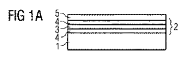
図1A〜図1Fに関する実施形態例では、薄膜半導体チップを製造するプロセス手順において、第1部品としてのエピタキシャル連続層が、接続層により、第2部品としてのキャリアウェハに接続される。 In the embodiment example related to FIGS. 1A to 1F, in a process procedure for manufacturing a thin film semiconductor chip, an epitaxial continuous layer as a first component is connected to a carrier wafer as a second component by a connection layer.
図1Aに関する放射線を発する薄膜半導体チップを生成するため、エピタキシャル連続層2が、例えばSiC又はサファイア基板等の適切な成長基板1にエピタキシャル成長される。そのエピタキシャル連続層は、活性ゾーン3、さらに機能層4を含む。活性ゾーン3では、作動中、放射線が発せられる。放射線を発するため、活性ゾーン3は、例えばpn接合、ダブルヘテロ構造、単量子井戸(single quantum well)、又はMQW(multiple quantum well)を有する。この場合、量子井戸構造は、量子化の次元に関する限定を含まない。したがって、量子井戸構造には、とりわけ、量子井戸、量子細線(quantum wires)、量子ドット(quantum dots)、又はそれらの構造の組合せも、含まれる。MQW構造の例は、国際公開第01/39282号パンフレット、米国特許第5831277号明細書、米国特許第6172383号明細書、及び米国特許第5684309号明細書に記載されている。この点についての開示内容は、ここに、参照により編入される。
To produce a thin film semiconductor chip that emits radiation with respect to FIG. 1A, an epitaxial
さらに、反射層5は、エピタキシャル連続層2の、成長基板1から離れた側に設けられる。その反射層は、活性ゾーン3で発せられた放射線を反射する。それは、上記成長基板1から離れた側でエピタキシャル連続層2から出現して再びエピタキシャル連続層2に戻るだろう。この場合、反射層5は、Au、Al、又はAg、又は3つの金属の合金を含み、独立した1つの層として、又は他の材料からなる層を含む連続層として、存在し得る。通常の薄膜半導体チップのエピタキシャル連続層2の厚さの合計は、数μm〜数十μmの範囲内にある。
Further, the
図1Bに関する続くステップでは、接続層7が、反射層5の、成長基板1から離れた側6に設けられる。この場合における上記の側は、第1部品の表面として機能する。この場合、反射層5の、成長基板1から離れた側6のマイクロプリズムパターニングを、事前のパターニング(prepatterning)として、有効に利用することができる。このことは、国際公開第02/13281号パンフレットに記載されている。この点についての開示内容は、ここに、参照により編入される。マイクロプリズムのための切り抜きは、例えばその上に反射層5が堆積され得る半導体層の中にエッチング形成することができる。反射層5により、エピタキシャル連続層2とのコンタクトを形成することを可能にするため、反射層5は、電気伝導性材料から形成されることが好ましい。接続ステップの後に続き、数多くのプロセスステップが実行されるため、とりわけ、耐溶解性、適切な真空度、及び/又は温度の安定性を有し、さらには続く全てのプロセス及びワークステップと互換性がある接続媒体を必要とする。接続層7にとって適切な材料の1つは、例えばBCBである。BCB(bisbenzocyclobutene)は、例えばダウコーニング(Dow Corning)社製の商標名Cyclotene 3022-xxから、得られる。ここで、xxは、メシチレン溶媒中の予備重合されたBCBモノマー(prepolymerized BCB monomers)の割合を明示する。BCBは、フォトレジストのように、スピンされることで、0.5〜10μmの範囲内の厚さをよく再現でき、一般に、接続すべき表面によく付着する。Cyclotene 3022-35又はCyclotene 3022-46を使用することで、それぞれ例えばその形成中に、約1.0〜約2.3μm又は約2.4〜約5.5μmの層厚を達成することから、この使用が有利であることが分かる。
In the subsequent step with respect to FIG. 1B, a
BCBフィルムの形成後、適宜、チタンマスクを用い、RIE(reactive ion etching)により、そのBCBフィルムを、パターニングすることができる。 After forming the BCB film, the BCB film can be patterned by RIE (reactive ion etching) using a titanium mask as appropriate.
別例として、Cyclotene 4022-xxを使用することで、例えばxx=35又はxx=46によりフォトパターニングが可能(photopatternable)になることから、この使用が有利であることが分かる。それとともに、それぞれ例えばその形成中に、約2.6〜約5.2μm又は約7.3〜約14.2μmの層厚を達成する。 As another example, the use of Cyclotene 4022-xx proves advantageous because it allows photopatterning, for example with xx = 35 or xx = 46. In conjunction therewith, for example, during its formation, a layer thickness of about 2.6 to about 5.2 μm or about 7.3 to about 14.2 μm is achieved.
これに代えて又は加えて、接続層7も、エピタキシャル連続層2に接続されるように、キャリア基板8に設けられる。
Instead of or in addition to this, the
図1Cに関する続く製造ステップでは、第2表面9を有する第2部品としてのキャリア基板8が、エピタキシャル連続層2に対して所望の相対位置になるように、接続層7上に配置される。キャリア基板8にとって適切な材料は、例えばシリコン又は金属のような電気伝導性材料、又は電気伝導性表面を有する電気絶縁性材料である。結果として、続く方法ステップでは、キャリア基板8により、簡単な方式で、電気的なコンタクトをエピタキシャル連続層2に形成することが可能になる。
In the subsequent manufacturing step with respect to FIG. 1C, the
図1Dに関する続く製造ステップでは、力10が、エピタキシャル連続層2で終わる反射層5の、及びキャリア基板8の、接続すべき表面6、9に対して実質上垂直に加えられる。結果として、接続層7の厚さは、例えば図2に示す実施形態例によれば、エピタキシャル連続層2で終わる反射層5の、及びキャリア基板8の、表面6、9の地形学的な表面構造の接触により、電気伝導性コンタクトが形成される程度まで、減少する。この場合、表面6、9の地形学的な表面構造は、有利には、図2の実施形態例に示されるように、粗さ最高点20、21になり得る。
In the subsequent manufacturing steps with respect to FIG. 1D, a
このように、図1Eによると、厚さが減少した接続層7は、広い範囲内で自由に選ぶことができる温度範囲により、適度な圧力で、硬化する。この場合、約20〜約78cm2の領域に対して約1〜約40kNの力が、適切であることが示される。
Thus, according to FIG. 1E, the
BCBは、例えば約150〜約200℃の範囲の温度で、硬化し得る。この場合、約150℃で約12時間、又は約200℃で約0.5時間、硬化させることが、特に有利であることが示される。さらに、低温、例えば約150℃で約3分間、事前硬化(pre-curing)を行うこと、また、より高い温度、例えば約200℃で約2分間、事後硬化(post-curing)を行うことで、有利となり得る。 BCB can be cured, for example, at temperatures in the range of about 150 to about 200 ° C. In this case, it is shown to be particularly advantageous to cure at about 150 ° C. for about 12 hours, or at about 200 ° C. for about 0.5 hour. Furthermore, by pre-curing at a low temperature, for example, about 150 ° C. for about 3 minutes, or by post-curing at a higher temperature, for example, about 200 ° C. for about 2 minutes. Can be advantageous.
接続層7の機械的負荷容量及び温度安定性に関する良好なプロセス互換性により、上記デバイスを、さらに処理することができる。良好なプロセス互換性は、続くプロセスステップが、特に接続層から、制限を受けない、又は不利な影響を受けない、という事実により明らかにされる。例えば接続層は、後の真空中のプロセスステップにとって不利なアウトガスがないことにより、エッチングプロセスに対する安定性により、また、後のプロセスステップの温度を有する接続層の互換性により、例えば本発明に係る接続層を有する半導体チップの製造方法に関して不利な影響が生じないようにすることを可能にし得る。
Due to the good process compatibility with regard to the mechanical load capacity and temperature stability of the
成長基板1は、研削により、薄膜化され又は完全に除去される。続く方法ステップでは、エピタキシャル連続層2とのコンタクトを形成するためのボンディングパッド12が、キャリア基板8から離れたエピタキシャル連続層2の表面11に設けられる(図1F参照)。電気的コンタクトは、半導体チップ13との間に形成され得る。これは、リード線により得られる。リード線は、キャリア基板8及びボンディングパッド12とのコンタクトを形成する。例えばリードフレームのような適切なキャリア基板上の半導体チップ13の配置は、図3〜図5の実施形態例に示される。
The growth substrate 1 is thinned or completely removed by grinding. In the subsequent method step, a
図示される方法は、成長基板上にエピタキシャル連続層を有する4インチエピタキシャルウェハの、キャリアウェハに対する大領域接続に使用される。 The illustrated method is used for large area connections to a carrier wafer of a 4 inch epitaxial wafer having an epitaxial continuous layer on a growth substrate.
図1A〜図1Fに図示される方法及びエピタキシャル連続層のパターニングは、例えば4インチキャリアウェハから、概ね約50000の薄膜半導体チップを生成することを可能にする。薄膜半導体チップの電気的コンタクト接続は、キャリアウェハにより、薄膜半導体チップの各々について、検査し、確かめることができる。 The method and epitaxial continuous layer patterning illustrated in FIGS. 1A-1F allows for the production of approximately 50,000 thin film semiconductor chips, for example, from a 4 inch carrier wafer. The electrical contact connection of the thin film semiconductor chip can be inspected and verified for each thin film semiconductor chip by means of the carrier wafer.
さらに、評価により、例えば本発明に係る方法により製造され、約90000μm2の接続層領域を有するチップが、少なくとも約700μm2のコンタクト位置領域を持っていることを確かめることができた。 Moreover, the evaluation is prepared, for example, by the method according to the present invention, a chip having a connection layer region of about 90000Myuemu 2 were able to verify that have at least about 700 .mu.m 2 contact location area.
キャリアウェハと薄膜半導体チップとの間の電気的コンタクト抵抗は、別の通常の半田接続と比較して、増加しない。 The electrical contact resistance between the carrier wafer and the thin film semiconductor chip does not increase compared to another normal solder connection.
図1Fに関する実施形態例とは違い、半導体チップ13との電気的コンタクトは、反射層5の、キャリア基板8に面する側6上のキャリア基板8を介して、またエピタキシャル連続層2の、キャリア基板8から離れた側11上のボンディングパッド12を介しても形成されず、エピタキシャル連続層2の一側上だけの電気的コンタクトパターンを介して形成される。電気的コンタクトパターンは、電気絶縁性接着剤からなる接続層7により、例えば伝導性テープパターン上のリード線パターンと電気的にコンタクト接続される。いわゆるフリップチップ実装は、例えば欧州特許出願公開第0905797号明細書に記載されている。この点についての開示内容は、ここに、参照により編入される。この場合、実装され、電気的コンタクト接続される薄膜半導体チップ13は、反射するように形成されるコンタクト5を有し、例えば伝導性テープ上等のリード線上へ配置される。そこには、受液溝として働く適切な窪み40が、反射するように形成されたコンタクト5のパターニングにより提供される。電気絶縁性接着剤は、本発明に係る接続層7として使用される。上記接着剤は、実装プロセスでの変動の結果としての短絡回路(short circuit)が基本的に避けられる、という利点を生む。例えば半導体チップの側領域、いわゆるチップフランク(chip flanks)を覆うような過剰な適用接着剤によってもエピタキシャル連続層の短絡回路を生じさせないことが可能になる。
Unlike the exemplary embodiment with respect to FIG. 1F, the electrical contact with the
本発明に係るデバイスの一例が、図2に関する実施形態例に示される。この場合、第1部品5の第1表面6及び第2部品8の第2表面9が、それぞれ地形学的な表面構造22、24を有する。地形学的な表面構造22、24は、例えば原子間力顕微鏡による測定で、高さプロファイルとして決定され得る。表面22の平均高さライン26及び表面24の平均高さライン27は、部品5、8の表面6、9を明示することができる。平均高さライン26と平均高さライン27との間の距離は、接続層7の厚さ28を定義する。図示される実施形態例では、表面構造22、24が、例えば粗さ最高点のような丘部(elevations)20、21を有し、その間には、窪みが配置され得る。図示されるように、それらの丘部は、例えば粗さプロファイルがパターニングされない場合などに、不規則に配置され得る。別例(図示せず)として、それらの丘部を、少なくとも部分的な領域で規則的に配置することもできる。
An example of a device according to the present invention is shown in the example embodiment with respect to FIG. In this case, the
第1部品5は、実施形態例1Aから、例えば反射層を有するエピタキシャル連続層となり得る。そこでは、第1表面が、反射層の、エピタキシャル連続層から離れた側となり、第2部品8がキャリア基板となり得る。別例として、第1部品5は、例えば後の実施形態例の1つに係る薄膜半導体チップ等の半導体チップ13ともなり得る。そこでは、例えば後の図に示されるように、第1表面6が、キャリア基板の、エピタキシャル連続層から離れた側となり得る。また、第2部品8が、表面実装可能な部品のハウジングのリードフレーム、又は半導体チップ13にとって適切な他の基板となり得る。
The
力10を加えることにより、部品5、8は、2つの表面6、9の地形学的な表面構造の丘部20、21が互いに接触するまで、互いに近づけられる。2つの部品5、8の表面6、9間の電気伝導性コンタクトは、これら互いに接触する丘部20、21により形成される。電気的コンタクトの全抵抗が小さいほど、より多くのコンタクトポイントが形成される。この場合、接続層の厚さ28は、概ね地形学的な表面構造22、24の高さプロファイル、換言すれば、例えば表面6、9の粗さに相当する。
By applying a
電気的コンタクトが部品5、8間に形成された状態で、接続層7は、接続層を形成する電気絶縁性接続媒体が丘部20、21間に配置されるように、成形され得る。これにより、部品5、8間の密着したコンタクトが確保される。
With electrical contacts formed between the
図3に関する実施形態例は、例えば方法1A〜1Fに関連して製造された薄膜半導体チップ等の半導体チップ13の実装を含む。上記チップは、表面実装可能な部品30に取り付けられている。表面実装可能な部品30は、例えばプラスチックからなるハウジング31と、表面実装可能な部品30の、例えばプリント回路基板上への実装及び電気的コンタクト接続を可能にするリードフレーム32と、を備える。一側に取り付けられる半導体チップ13は、実施形態例1Fに係る薄膜半導体チップの場合において、キャリア基板8の、エピタキシャル連続層2から離れた側から、電気絶縁性接着剤からなる接続層7により、ハウジング31内のリードフレーム32へ取り付けられ、電気的及び熱的に、リードフレーム32と結合される。この場合、リードフレーム32は、リード線として作用するだけでなく、半導体チップ13で生じる熱を放散させるためのヒートシンクとしても役に立つ。特に電気伝導性接着剤の典型的な金属フィリング無しで、薄い電気絶縁性接続層7を使用することにより、その熱を特によく放散させることができる。
The example embodiment with respect to FIG. 3 includes the mounting of a
図1A〜図1Fに示される実施形態例に係る方法に関連して、同様のプロセスパラメータで、BCBからなる接続層を有利に使用することが可能になる。取り付け、換言すれば、例えばリードフレーム32への半導体チップ13の配置は、時間的及び空間的に、接続層7の硬化から分離して行うことができる。
In connection with the method according to the exemplary embodiment shown in FIGS. 1A to 1F, with similar process parameters, it is possible to advantageously use a connection layer consisting of BCB. For example, the
図4Aに関する実施形態例は、リードフレーム32上に実装された半導体チップ13を示す。ここでは、リードフレーム32、典型的には金属製テープが、接続層7の電気絶縁性接着剤のための窪み40を有するように、エンボス加工により変形している。半導体チップ13がリードフレーム32へ配置される時、接続層7の厚さを減少させるように、プレスによる力が、接続層7として適用される接着剤に圧力を加える。この場合、接続層7に含まれる余分な接着剤は、接着剤のための収集貯液部として機能する窪み40へ押し出される。この場合、接合領域41内の接着剤の厚さは、電気伝導性コンタクトが半導体チップ13とリードフレーム32との間に生じるまで減少する。収集貯液部として機能する窪み40により、排出された余分な接着剤は、実装すべき半導体チップ13の周囲に生じない。これは、半導体チップ13を、クリーンに、伝導性テープ32上にコンタクト接続及び実装することを可能にする。
The example embodiment with respect to FIG. 4A shows a
図4Bに関する実施形態例では、実施形態1Fに関する実装すべき半導体チップ13が、接着剤のための収集貯液部として役に立つ窪み40を有する。上記窪み40は、キャリア基板8の、エピタキシャル連続層2から離れた側のパターンによっても、また、結晶学的なエッチング作用を含む研削プロセスの相互作用の結果として生じる粗さによっても、提供され得る。
In the example embodiment with respect to FIG. 4B, the
コンタクトは、ボンディングパッド12により、例えば半導体チップの、リードフレームから離れた側に、図4Aの実施形態例に関する半導体チップ13、又は図4Bの実施形態例に関する半導体チップ13を用いて、形成され得る。別例として、半導体チップの両側についてのコンタクト接続の可能性は、半導体チップの、伝導性テープ32に面する側でフリップチップ実装する場合に、提供され得る(図示せず)。また、ボンディングパッド12の付属品は、割愛し得る。
The contacts can be formed by
図5に関する実施形態例では、放射線を発する半導体チップ13が、透明な電気伝導性酸化物(Transparent Conductive Oxide、略してTCO)を含む、又はTCOからなる層51に覆われた透明な基板50に実装される。TCOsは、透明な電気伝導性材料、一般には、例えば酸化亜鉛(zinc oxide)、酸化スズ(tin oxide)、酸化カドミウム(cadmium oxide)、酸化チタン(titanium oxide)、酸化インジウム(indium oxide)、又はインジウムスズ酸化物(indium tin oxide:ITO)のような、金属酸化物である。並んで、例えばZnO、SnO2、In2O3のような、2成分の金属−酸素化合物、例えばZn2SnO4、CdSnO3、ZnSnO3、MgIn2O4、GaInO3、Zn2In2O5、又はIn4Sn3O12のような、3成分の金属−酸素化合物、又は異なる透明な導電性酸化物の混合物も、TCOsのグループに属する。さらに、ストイキオメトリーな組成に一致する必要はなく、p型又はn型のドーピングをしてもよい。半導体チップ13は、UV光で硬化し得る電気絶縁性接着剤からなる接続層7により、透明な基板50に固定される。この場合、図1A〜図1Fに示される実施形態例の方法に関連して生じ得る半導体チップ13は、キャリア基板8が基板50に面するように、基板に配置される。キャリア基板は、有利には透明に形成され、ガラス又は他の透明な材料を含む又はこれらからなる。結果として、半導体チップ13により発せられる放射線は、半導体チップ13のキャリア基板8を通って、また、接続層7、層51、及び透明な基板50を通って、発せられ得る。接続層7を設け、半導体チップ13を位置決めした後、力を加えることにより、図2の実施形態例に示されるように、例えば両部品の地形学的な表面構造の、粗さ最高点等の複数の丘部の間の接触ポイントの配列により電気伝導性コンタクトが半導体チップ8と層51との間に形成されるまで、半導体チップと層51との間の距離が減少する。また、電気絶縁性接着剤は、例えばUV光の使用により硬化し得、透明な基板50の上記の側から接続層7へ光を当てられ得る。電気的コンタクトは、例えば一乃至複数の金属を含む、又は一乃至複数の金属からなるコンタクト位置を介して、形成され得る。そのようなコンタクト位置は、特に適切な半導体チップからの距離で、層51上の、例えば半導体チップ13の傍に配置され得る(図示せず)。
In the exemplary embodiment with reference to FIG. 5, the
半導体チップの、基板50から離れ、マイクロプリズムパターニングを有し得る側は、例えば同様の方式でコンタクト接続し得る。この場合、ガラスを含む又はガラスからなる別の透明な基板52は、例えば加えて、半導体チップ13の基板50から離れた側に配置され得る。透明な基板52は、TCOを含む又はTCOからなる電気伝導性層53で覆われ得る。半導体チップ13の電気伝導性層53への電気伝導性接続は、同様に接続層7を介してなされ得る。さらに、例えば電気絶縁性接着剤のような電気絶縁性材料からなる接続層7を使用することにより、半導体チップ13の上記の側の領域131、132に接合する領域54が、接続層材料で満たされる。半導体チップの短絡回路は、電気絶縁性接続層材料を使用することにより避けられる。
The side of the semiconductor chip that is away from the
別例として、基板50は、不透明であってもよく、基板52は、透明であってもよい。
As another example, the
図6Aは、2つの電気的コンタクト領域51、52を有する第1部品5を備える実施形態例を示す。第1部品5は、図示される一例にすぎないが、この場合には、一側上に電気的コンタクト領域51、52を介して電気的コンタクトがなされ得るエピタキシャル連続層として、形成される。この目的では、第1部品5が、連続的な第1表面6を有する。これは、電気的コンタクト領域51、52により、電気的に接続され得る。図示される実施形態例では、電気的コンタクト領域51、52が、異なる極性を有する。別例として、電気的コンタクト領域51、52は、第1表面6上に、パターニングされたコンタクト領域51、52を介して、1つの極性だけに関して第1部品の電気的接続がなし得るような、同一の電気的極性も有し得る。別例として、第1表面6は、同一の又は異なる極性を有する2つ以上の電気的コンタクト領域を有し得る。
FIG. 6A shows an example embodiment comprising a
第1部品5は、2つの電気的コンタクト領域81、82を有するキャリアである第2部品8上に配置される。この場合、そのキャリアは、キャリア基板として、又は例えば第2表面を有するリードフレームとして、形成され得る。これは、第1表面6上に、電気的コンタクト領域51、52の数と一致する電気的コンタクト領域81、82を有する。別例として、第2表面9上の電気的コンタクト領域は、第2表面上の1つ以上の電気的コンタクト領域とのコンタクトもなし得る。また、逆も同様である(図示せず)。
The
第1部品5は、固定され、表面6及び9間に配置された接続層7により、第2部品8上に電気的コンタクト接続される。この場合、接続層7は、先の実施形態例と同様に形成され、例えばBCB等の電気絶縁性接着剤を有する。
The
電気的コンタクト領域81、82の上の電気的コンタクト領域51、52の配置、及び、各々の表面6及び9の粗さ最高点が互いに接触し得るまでの接続層7の厚さの縮小により、電気的コンタクト領域51及び81と電気的コンタクト領域52及び82との間の電気的コンタクトを実現することが可能になる。この目的のため、図示される実施形態例のような接続層7は、連続的でパターニングされず、電気的コンタクト領域51、52、81、82の上を連続的な層として広がる。接続層が電気絶縁性接着剤からなるという事実により、第2部品8への第1部品5の大きな領域の密着固定が、電気的コンタクト領域51及び52と81及び82との間にそれぞれ短絡回路を生じさせずに、成し得る。
Due to the arrangement of the
図6Bに示される実施形態例では、第1部品5及び第2部品8が、それぞれ高い電気的コンタクト領域51、52及び81、82を有する。第1部品5は、例えばフリップチップ実装のための半導体チップとなり得る。これは、第2部品8として、リードフレーム81、82を有するキャリアに設けられる。第1部品5の第2部品8への密着固定及び電気的接続は、上記方法で、接続層7を介してなされる。これは、各々の電気的コンタクト領域51及び81と52及び82との間にそれぞれ設けられる。
In the example embodiment shown in FIG. 6B, the
図6Cは、より良好な第1部品5の第2部品8への密着固定が可能になるように、接続層7が電気的コンタクト領域51、52、81、82の間にも配置される、別の実施形態例を示す。
FIG. 6C shows that the
図6Dに示される実施形態例は、電気的コンタクト領域81、82の上に追加の層を有する第2部品8を示す。これは、例えばSiO2のような酸化物等の絶縁材料801を含む。絶縁材料801は、それぞれ第2部品8の電気的コンタクト領域81及び82とのコンタクトをなす金属フィリング811、812、821、822を含有する。第1部品5は、その絶縁材料801を含む層の上に配置される。例えばパターニングされた電気的コンタクト領域51、52を有するエピタキシャル連続層が、上記方法で、接続層7により、それぞれ金属フィリング811、812及び821、822へ、また第2部品8の電気的コンタクト領域81、82へも、電気的に接続される。第2部品8は、例えばリード線81、82を用いる基板として形成され得る。この基板の上には、絶縁材料801及び金属フィリング811、812、821、822を含む上記層が配置される。別例として、金属フィリング811、812、821、822は、材料801が電気伝導性材料にもなり得るように、材料801との境界で、絶縁材料からなる層により、囲まれ得る。
The example embodiment shown in FIG. 6D shows a
図6Eに示される実施形態例では、金属フィリング811、812、821、822が、材料801よりも高くなる方法で、例えばマッシュルーム構造で、形成される。この場合、電気的コンタクトが、接続層7の厚さの十分な縮小により、金属フィリング811、812、821、822の第2表面9と電気的コンタクト領域51及び52の第1表面6との間に生じる。
In the example embodiment shown in FIG. 6E, the
適切な分布及び適切な寸法により、特に図示される実施形態例の金属フィリング811、812、821、822の寸法により、第2部品8への、第1部品5のアライメントフリー(位置決め不要)のコンタクト接続を実現することが可能になる。この場合、金属フィリングの数は、図示される数から分けることができる。これに代えて又は加えて、第1及び/又は第2部品は、金属フィリングの寸法及び配置に対する制約を取り除くことができるように、例えばガイド部又はガイド端のようなアライメント要素を有し得る。
Alignment-free (positioning-free) contact of the
本発明は、上記実施形態に基づく上記記述により、上記実施形態に限定されない。むしろ、本発明は、いかなる新しい特徴、及びいかなる特徴の組合せも、また特に、特許請求の範囲におけるいかなる特徴の組合せも、含む。これは、たとえ、この特徴又は特徴の組合せが、特許請求の範囲又は実施形態において、はっきりと明示されていない場合でも、である。 The present invention is not limited to the above embodiment by the above description based on the above embodiment. Rather, the present invention includes any new features and combinations of features, and in particular any combination of features in the claims. This is the case even if this feature or combination of features is not explicitly stated in the claims or embodiments.
Claims (39)
前記第1導体表面及び前記第2導体表面の少なくとも1つが、前記第1導体表面及び/又は前記第2導体表面の粗さにより生じる地形学的な表面構造を有し、
前記第1部品(5)の前記第1導体表面(6)は、部分的に、前記第2部品(8)の前記第2導体表面(9)に直接接続するとともに、部分的に、電気絶縁性接続層(7)を介して前記第2部品(8)の前記第2導体表面(9)に接続され、そして、
前記直接接続により、前記第1導体表面(6)と前記第2導体表面(9)との間に、前記地形学的な表面構造を介して電気伝導性コンタクトがある、
ことを特徴とするデバイス。 In a device comprising a first part (5) having a first conductor surface (6) and a second part (8) having a second conductor surface (9),
At least one of the first conductor surface and the second conductor surface has a topographical surface structure caused by roughness of the first conductor surface and / or the second conductor surface;
The first conductor surface (6) of the first part (5) is partly connected directly to the second conductor surface (9) of the second part (8) and partly electrically insulated. Connected to the second conductor surface (9) of the second component (8) via a conductive connection layer (7), and
Due to the direct connection, there is an electrically conductive contact between the first conductor surface (6) and the second conductor surface (9) via the topographic surface structure,
A device characterized by that.
ことを特徴とする請求項1に記載のデバイス。Both the first conductor surface and the second conductor surface have a topographic surface structure;
The device according to claim 1.
ことを特徴とする請求項1又は2に記載のデバイス。The first component (5) and / or the second component (8) is selected from the group consisting of a substrate, a wafer, a glass carrier, a heat sink, an epitaxial continuous layer, and an optoelectronic semiconductor chip.
The device according to claim 1 or 2, characterized in that
ことを特徴とする請求項1乃至3のうちいずれか一項に記載のデバイス。The first conductor surface (6) of the first part (5) and / or the second conductor surface (9) of the second part (8) have a recess (40),
The device according to claim 1, wherein the device is a device.
前記接合領域(41)には、前記接続層(7)が取り付けられ、
前記第1導体表面(6)及び/又は前記第2導体表面(9)の前記窪み(40)は、前記接合領域(41)の周囲に配置される、
ことを特徴とする請求項4に記載のデバイス。The first conductor surface (6) and the second conductor surface (9) have a joint region (41);
The connection layer (7) is attached to the joining region (41),
The depression (40) of the first conductor surface (6) and / or the second conductor surface (9) is arranged around the joining region (41);
The device of claim 4.
ことを特徴とする請求項4又は5に記載のデバイス。The recess (40) serves as a collection reservoir for the adhesive of the connection layer,
6. A device according to claim 4 or 5, characterized in that
ことを特徴とする請求項4乃至6のうちいずれか一項に記載のデバイス。The plurality of depressions (40) are arranged such that they are regularly spaced apart.
A device according to any one of claims 4 to 6, characterized in that
ことを特徴とする請求項4乃至6のうちいずれか一項に記載のデバイス。A plurality of said depressions (40) are arranged such that they are spaced apart irregularly,
A device according to any one of claims 4 to 6, characterized in that
ことを特徴とする請求項1乃至8のうちいずれか一項に記載のデバイス。 A device according to any one of claims 1 to 8, characterized in that
ことを特徴とする請求項1乃至9のうちいずれか一項に記載のデバイス。 The device according to claim 1, wherein the device is a device.
前記第2導体表面の前記地形学的な表面構造は、該第2導体表面のエンボス加工より形 The topographic surface structure of the surface of the second conductor is shaped by embossing the surface of the second conductor. 成される、Made,
ことを特徴とする請求項10に記載のデバイス。 The device according to claim 10.
前記第2部品は、異なる極性を有する一対の第2コンタクト領域を有し、
前記一対の第1コンタクト領域はそれぞれ、前記地形学的な表面構造を有する前記第1導体表面を構成し、
前記一対の第2コンタクト領域はそれぞれ、前記地形学的な表面構造を有する前記第2導体表面を構成し、
同じ極性の前記第1コンタクト領域と前記第2コンタクト領域とがそれぞれ、部分的に直接接続し、且つ、部分的に前記電気絶縁性接続層を介して接続されることで、前記直接接続により、各コンタクト領域間に電気伝導性コンタクトが形成される、
ことを特徴とする請求項1乃至11のうちいずれか一項に記載のデバイス。 The first component has a pair of first contact regions having different polarities,
The second component has a pair of second contact regions having different polarities,
Each of the pair of first contact regions constitutes the first conductor surface having the topographic surface structure;
Each of the pair of second contact regions constitutes the second conductor surface having the topographic surface structure;
The first contact region and the second contact region having the same polarity are partially connected directly and partially connected via the electrically insulating connection layer, whereby the direct connection allows An electrically conductive contact is formed between each contact region,
The device according to claim 1, wherein the device is a device.
前記第2部品は、同じ極性を有する複数の第2コンタクト領域を有し、
前記複数の第1コンタクト領域はそれぞれ、前記地形学的な表面構造を有する前記第1導体表面を構成し、
前記複数の第2コンタクト領域はそれぞれ、前記地形学的な表面構造を有する前記第2導体表面を構成し、
前記第1コンタクト領域と該第1コンタクト領域に対応する前記第2コンタクト領域とがそれぞれ、部分的に直接接続し、且つ、部分的に前記電気絶縁性接続層を介して接続されることで、前記直接接続により、各コンタクト領域間に電気伝導性コンタクトが形成される、
ことを特徴とする請求項1乃至11のうちいずれか一項に記載のデバイス。 The first component has a plurality of first contact regions having the same polarity,
The second component has a plurality of second contact regions having the same polarity,
Each of the plurality of first contact regions constitutes the first conductor surface having the topographic surface structure;
Each of the plurality of second contact regions constitutes the second conductor surface having the topographic surface structure;
The first contact region and the second contact region corresponding to the first contact region are each partially connected directly and partially connected via the electrically insulating connection layer, By the direct connection , an electrically conductive contact is formed between each contact region,
The device according to claim 1, wherein the device is a device.
ことを特徴とする請求項1乃至13のうちいずれか一項に記載のデバイス。The average thickness (28) of the connection layer (7) is approximately the size of the roughness of the first conductor surface (6) and / or the roughness of the second conductor surface (9).
Device according to any one of claims 1 to 13, characterized in that.
ことを特徴とする請求項1乃至14のうちいずれか一項に記載のデバイス。The roughness of the first conductor surface (6) and / or the roughness of the second conductor surface (9) is at least a few nanometers (nm),
15. A device according to any one of claims 1 to 14 , characterized in that
ことを特徴とする請求項1乃至15のうちいずれか一項に記載のデバイス。Said first conductor surface (6) and / or the second conductor surface (9) is formed on the steel metals,
The device according to claim 1 , wherein the device is a device.
ことを特徴とする請求項1乃至16のうちいずれか一項に記載のデバイス。The connection layer includes an electrically insulating adhesive,
Device according to any one of claims 1 to 16, wherein the.
ことを特徴とする請求項17に記載のデバイス。The adhesive is resistant to dissolution, suitable vacuum, temperature stable and / or UV curable,
The device of claim 17 .
ことを特徴とする請求項17又は18に記載のデバイス。The adhesive contains BCB (BisbenzoCycloButene),
19. A device according to claim 17 or 18 , characterized in that
前記第1導体表面及び前記第2導体表面の少なくとも1つが、前記第1導体表面及び/又は前記第2導体表面の粗さにより生じる地形学的な表面構造を有し、
前記第1導体表面及び/又は前記第2導体表面へ電気絶縁性接続層(7)を設ける工程と、
互いに関して前記第1導体表面(6)と前記第2導体表面(9)とを位置決めする工程と、
前記第1導体表面(6)と前記第2導体表面(9)とが部分的に前記電気絶縁性接続層(7)を介して接続されるとともに、前記第1導体表面(6)と前記第2導体表面(9)とが部分的に直接接続されることにより前記第1導体表面(6)と前記第2導体表面(9)との間に前記地形学的な表面構造を介して電気的伝導性コンタクトが生じるまで、前記第1部品(5)及び/又は前記第2部品(8)へ力(10)を加える工程と、
を含む、
ことを特徴とする電気伝導性接続部の製造方法。 A method of manufacturing an electrically conductive connection between a first part (5) having a first conductor surface (6) and a second part (8) having a second conductor surface (9),
At least one of the first conductor surface and the second conductor surface has a topographical surface structure caused by roughness of the first conductor surface and / or the second conductor surface;
Providing an electrically insulating connection layer (7) on the first conductor surface and / or the second conductor surface;
Positioning the first conductor surface (6) and the second conductor surface (9) with respect to each other;
The first conductor surface (6) and the second conductor surface (9) are partially connected via the electrically insulating connection layer (7), and the first conductor surface (6) and the first conductor surface (6) The two conductor surfaces (9) are partially connected directly to each other through the topographic surface structure between the first conductor surface (6) and the second conductor surface (9). Applying a force (10) to the first part (5) and / or the second part (8) until a conductive contact occurs;
including,
A method for manufacturing an electrically conductive connecting portion.
ことを特徴とする請求項20に記載の製造方法。The first conductor surface (6) and the second conductor surface (9) have a topographic surface structure;
The manufacturing method according to claim 20 , wherein:
ことを特徴とする請求項20又は21に記載の製造方法。The topographic surface structure is formed before the connection layer is provided,
The manufacturing method according to claim 20 or 21 , characterized in that:
ことを特徴とする請求項22に記載の製造方法。The topographic surface structure is formed by etching, grinding, photolithography patterning, and / or sandblasting,
The manufacturing method according to claim 22 .
ことを特徴とする請求項20乃至23のうちいずれか一項に記載の製造方法。The first component (5) and / or the second component (8) is used selected from the group consisting of a substrate, a wafer, a glass carrier, a heat sink, an epitaxial continuous layer, and an optoelectronic semiconductor chip.
24. The manufacturing method according to any one of claims 20 to 23 , wherein:
ことを特徴とする請求項20乃至24のうちいずれか一項に記載の製造方法。The first conductor surface (6) of the first part (5) and / or the second conductor surface (9) of the second part (8) have a recess (40) and are electrically insulating. Prepared before the connection layer is provided,
25. The manufacturing method according to any one of claims 20 to 24 .
前記接合領域(41)には、前記接続層(7)が取り付けられ、
前記第1導体表面(6)及び/又は前記第2導体表面(9)の前記窪み(40)は、前記接合領域(41)の周囲に配置される、
ことを特徴とする請求項25に記載の製造方法。 The first conductor surface (6) and the second conductor surface (9) have a joint region (41);
The connection layer (7) is attached to the joining region (41),
The depression (40) of the first conductor surface (6) and / or the second conductor surface (9) is arranged around the joining region (41);
26. The manufacturing method according to claim 25 .
ことを特徴とする請求項25又は26に記載の製造方法。The recess (40) serves as a collection reservoir for the adhesive of the connection layer,
27. The manufacturing method according to claim 25 or 26 .
ことを特徴とする請求項25乃至27のうちいずれか一項に記載の製造方法。The plurality of depressions (40) are arranged such that they are regularly spaced apart.
The manufacturing method according to any one of claims 25 to 27 , wherein:
ことを特徴とする請求項25乃至27のうちいずれか一項に記載の製造方法。A plurality of said depressions (40) are arranged such that they are spaced apart irregularly,
The manufacturing method according to any one of claims 25 to 27 , wherein:
ことを特徴とする請求項25乃至29のうちいずれか一項に記載の製造方法。The recess (40) is formed by etching, grinding, embossing, photolithography patterning, and / or sandblasting,
30. The manufacturing method according to any one of claims 25 to 29 , wherein:
ことを特徴とする請求項20乃至30のうちいずれか一項に記載の製造方法。The connection layer (7) is formed by patterning.
The manufacturing method according to any one of claims 20 to 30, wherein the manufacturing method is performed.
ことを特徴とする請求項31に記載の製造方法。The patterned connection layer is formed by a printing method.
32. The manufacturing method according to claim 31 , wherein:
ことを特徴とする請求項20乃至30のうちいずれか一項に記載の製造方法。The connection layer (7) is provided without patterning.
The manufacturing method according to any one of claims 20 to 30, wherein the manufacturing method is performed.
ことを特徴とする請求項33に記載の製造方法。The non-patterned connection layer is formed by spin coating or vapor deposition.
34. The manufacturing method according to claim 33 .
ことを特徴とする請求項20乃至34のうちいずれか一項に記載の製造方法。The thickness (28) of the connection layer (7) after installation has a thickness of 100 nm to 10 μm.
35. The manufacturing method according to any one of claims 20 to 34, wherein:
ことを特徴とする請求項35に記載の製造方法。The force applied so that the thickness (28) of the connection layer (7) is approximately the roughness of the first conductor surface (6) and / or the roughness of the second conductor surface (9). (10) to reduce after installation,
36. The manufacturing method according to claim 35 .
ことを特徴とする請求項20乃至36のうちいずれか一項に記載の製造方法。An electrically insulating connection layer containing an adhesive is used,
37. The manufacturing method according to any one of claims 20 to 36 , wherein:
ことを特徴とする請求項37に記載の製造方法。Adhesives that are resistant to dissolution, suitable vacuum, temperature stable and / or UV curable are used,
The manufacturing method according to claim 37 , wherein:
ことを特徴とする請求項37又は38に記載の製造方法。Adhesives containing BCB (BisbenzoCycloButene) are used,
The manufacturing method according to claim 37 or 38 , wherein:
Applications Claiming Priority (5)
| Application Number | Priority Date | Filing Date | Title |
|---|---|---|---|
| DE102006023683 | 2006-05-19 | ||
| DE102006023683.1 | 2006-05-19 | ||
| DE102006028692.8A DE102006028692B4 (en) | 2006-05-19 | 2006-06-22 | Electrically conductive connection with an insulating connection medium |
| DE102006028692.8 | 2006-06-22 | ||
| PCT/DE2007/000897 WO2007134581A1 (en) | 2006-05-19 | 2007-05-16 | Electrically conducting connection with insulating connection medium |
Publications (3)
| Publication Number | Publication Date |
|---|---|
| JP2009537970A JP2009537970A (en) | 2009-10-29 |
| JP2009537970A5 JP2009537970A5 (en) | 2011-07-07 |
| JP5208922B2 true JP5208922B2 (en) | 2013-06-12 |
Family
ID=38488603
Family Applications (1)
| Application Number | Title | Priority Date | Filing Date |
|---|---|---|---|
| JP2009510280A Active JP5208922B2 (en) | 2006-05-19 | 2007-05-16 | Device and manufacturing method of electrically conductive connection part |
Country Status (7)
| Country | Link |
|---|---|
| US (1) | US8102060B2 (en) |
| EP (1) | EP2018664A1 (en) |
| JP (1) | JP5208922B2 (en) |
| KR (1) | KR101367545B1 (en) |
| DE (1) | DE102006028692B4 (en) |
| TW (1) | TWI357639B (en) |
| WO (1) | WO2007134581A1 (en) |
Families Citing this family (19)
| Publication number | Priority date | Publication date | Assignee | Title |
|---|---|---|---|---|
| DE102006023685A1 (en) | 2005-09-29 | 2007-04-05 | Osram Opto Semiconductors Gmbh | Optoelectronic semiconductor chip for emitting electromagnetic radiation, has support substrate comprising material from group of transparent conducting oxides, where substrate mechanically supports semiconductor layered construction |
| DE102006035627A1 (en) * | 2006-07-31 | 2008-02-07 | Osram Opto Semiconductors Gmbh | LED semiconductor body |
| US7977799B2 (en) * | 2008-04-30 | 2011-07-12 | Avago Technologies Wireless Ip (Singapore) Pte. Ltd. | Planar packageless semiconductor structure with via and coplanar contacts |
| DE102008030816B4 (en) * | 2008-06-30 | 2019-11-07 | Osram Oled Gmbh | Method for producing a component with at least one organic material |
| DE102011100457A1 (en) | 2011-05-04 | 2012-11-08 | Osram Opto Semiconductors Gmbh | Electronic part, has connection structure comprising foil with front and back surfaces, where front/back surface is formed such that front/back surface contacts chip/carrier element and is spaced from chip/carrier element, respectively |
| US9337387B2 (en) | 2011-06-15 | 2016-05-10 | Sensor Electronic Technology, Inc. | Emitting device with improved extraction |
| KR20140047070A (en) | 2011-06-15 | 2014-04-21 | 센서 일렉트로닉 테크놀로지, 인크 | Device with inverted large scale light extraction structures |
| US10522714B2 (en) | 2011-06-15 | 2019-12-31 | Sensor Electronic Technology, Inc. | Device with inverted large scale light extraction structures |
| US9741899B2 (en) | 2011-06-15 | 2017-08-22 | Sensor Electronic Technology, Inc. | Device with inverted large scale light extraction structures |
| US10319881B2 (en) | 2011-06-15 | 2019-06-11 | Sensor Electronic Technology, Inc. | Device including transparent layer with profiled surface for improved extraction |
| EP2858106B1 (en) * | 2012-05-30 | 2019-05-08 | Olympus Corporation | Method for producing semiconductor apparatus |
| EP2858105A4 (en) | 2012-05-30 | 2016-05-18 | Olympus Corp | Imaging device, semiconductor device, and imaging unit |
| WO2013179765A1 (en) * | 2012-05-30 | 2013-12-05 | オリンパス株式会社 | Imaging device manufacturing method and semiconductor device manufacturing method |
| DE102012112988A1 (en) | 2012-12-21 | 2014-07-10 | Osram Opto Semiconductors Gmbh | Optoelectronic component, method for producing an optoelectronic component and headlight |
| DE102014115770B4 (en) * | 2014-10-30 | 2018-03-29 | Infineon Technologies Ag | METHOD FOR CONNECTING A SUBSTRATE |
| US9721812B2 (en) * | 2015-11-20 | 2017-08-01 | International Business Machines Corporation | Optical device with precoated underfill |
| US10461221B2 (en) | 2016-01-18 | 2019-10-29 | Sensor Electronic Technology, Inc. | Semiconductor device with improved light propagation |
| DE102016103324A1 (en) * | 2016-02-25 | 2017-08-31 | Osram Opto Semiconductors Gmbh | Video wall module and method of making a video wall module |
| KR20220065292A (en) | 2020-11-13 | 2022-05-20 | 삼성전자주식회사 | Semiconductor package and method of manufacturing the same |
Family Cites Families (29)
| Publication number | Priority date | Publication date | Assignee | Title |
|---|---|---|---|---|
| US3666588A (en) * | 1970-01-26 | 1972-05-30 | Western Electric Co | Method of retaining and bonding articles |
| DE3001613C2 (en) * | 1980-01-17 | 1986-04-03 | Siemens AG, 1000 Berlin und 8000 München | Attachment of a silicon semiconductor body containing a monolithically integrated semiconductor circuit to a support using a corresponding method for this purpose |
| JPS60262430A (en) * | 1984-06-08 | 1985-12-25 | Matsushita Electric Ind Co Ltd | Manufacture of semiconductor device |
| DE4122297A1 (en) | 1991-07-05 | 1993-01-07 | Messerschmitt Boelkow Blohm | Electronic or optical appts. esp. semiconductor appts. - having junctions in the form of metallised bonding pads |
| DE69320098T2 (en) * | 1992-05-15 | 1999-04-01 | Denso Corp | PTC thermistor for heaters and manufacturing processes |
| US5548091A (en) * | 1993-10-26 | 1996-08-20 | Tessera, Inc. | Semiconductor chip connection components with adhesives and methods for bonding to the chip |
| WO1996037913A1 (en) * | 1995-05-22 | 1996-11-28 | Hitachi Chemical Company, Ltd. | Semiconductor device having a semiconductor chip electrically connected to a wiring substrate |
| DE19529490A1 (en) | 1995-08-10 | 1997-02-13 | Fraunhofer Ges Forschung | Chip contacting method, electronic circuit produced therewith and carrier substrate for contacting chips |
| US5684309A (en) | 1996-07-11 | 1997-11-04 | North Carolina State University | Stacked quantum well aluminum indium gallium nitride light emitting diodes |
| US5789278A (en) * | 1996-07-30 | 1998-08-04 | Micron Technology, Inc. | Method for fabricating chip modules |
| CN100485984C (en) | 1997-01-09 | 2009-05-06 | 日亚化学工业株式会社 | Nitride semiconductor device |
| US5831277A (en) | 1997-03-19 | 1998-11-03 | Northwestern University | III-nitride superlattice structures |
| EP0905797B1 (en) | 1997-09-29 | 2010-02-10 | OSRAM Opto Semiconductors GmbH | Semiconductor light source and method of fabrication |
| US5861678A (en) * | 1997-12-23 | 1999-01-19 | Micron Technology, Inc. | Method and system for attaching semiconductor dice to substrates |
| DE69936235T2 (en) * | 1998-02-26 | 2007-09-13 | Ibiden Co., Ltd., Ogaki | Multilayer printed circuit board with filled contact holes |
| DE19955747A1 (en) | 1999-11-19 | 2001-05-23 | Osram Opto Semiconductors Gmbh | Optical semiconductor device with multiple quantum well structure, e.g. LED, has alternate well layers and barrier layers forming super-lattices |
| US6426565B1 (en) | 2000-03-22 | 2002-07-30 | International Business Machines Corporation | Electronic package and method of making same |
| US6404566B1 (en) * | 2000-04-04 | 2002-06-11 | Lucent Technologies Inc. | Apparatus and method for assembling optical devices |
| DE10046296C2 (en) * | 2000-07-17 | 2002-10-10 | Infineon Technologies Ag | Electronic chip component with an integrated circuit and method for its production |
| US20020017652A1 (en) | 2000-08-08 | 2002-02-14 | Stefan Illek | Semiconductor chip for optoelectronics |
| CN1498417A (en) * | 2000-09-19 | 2004-05-19 | 纳诺皮尔斯技术公司 | Method for assembling components and antenna in radio frequency identification devices |
| DE10163799B4 (en) | 2000-12-28 | 2006-11-23 | Matsushita Electric Works, Ltd., Kadoma | Semiconductor chip mounting substrate and method of manufacturing such a mounting substrate |
| DE10149507A1 (en) * | 2001-10-06 | 2003-04-10 | Behr Gmbh & Co | Heat exchanger, in particular flat-tube heat exchanger of a motor vehicle |
| US6962835B2 (en) * | 2003-02-07 | 2005-11-08 | Ziptronix, Inc. | Method for room temperature metal direct bonding |
| DE10319782B4 (en) * | 2003-04-30 | 2009-01-02 | Osram Opto Semiconductors Gmbh | Optoelectronic semiconductor component with a chip carrier element |
| JP2004349399A (en) * | 2003-05-21 | 2004-12-09 | Nec Corp | Component mounting substrate |
| DE102004030813B4 (en) | 2004-06-25 | 2007-03-29 | Infineon Technologies Ag | Method for connecting an integrated circuit to a substrate and corresponding circuit arrangement |
| JP4565931B2 (en) * | 2004-08-25 | 2010-10-20 | ルネサスエレクトロニクス株式会社 | Manufacturing method of semiconductor device |
| JP2006114656A (en) * | 2004-10-14 | 2006-04-27 | Seiko Epson Corp | Semiconductor device, and structure and method of packaging the same |
-
2006
- 2006-06-22 DE DE102006028692.8A patent/DE102006028692B4/en active Active
-
2007
- 2007-05-16 KR KR1020087030710A patent/KR101367545B1/en active IP Right Grant
- 2007-05-16 JP JP2009510280A patent/JP5208922B2/en active Active
- 2007-05-16 US US12/301,566 patent/US8102060B2/en active Active
- 2007-05-16 EP EP07722445A patent/EP2018664A1/en not_active Withdrawn
- 2007-05-16 WO PCT/DE2007/000897 patent/WO2007134581A1/en active Application Filing
- 2007-05-17 TW TW096117569A patent/TWI357639B/en not_active IP Right Cessation
Also Published As
| Publication number | Publication date |
|---|---|
| JP2009537970A (en) | 2009-10-29 |
| EP2018664A1 (en) | 2009-01-28 |
| TW200807646A (en) | 2008-02-01 |
| US20090302429A1 (en) | 2009-12-10 |
| DE102006028692B4 (en) | 2021-09-02 |
| DE102006028692A1 (en) | 2007-11-22 |
| WO2007134581A1 (en) | 2007-11-29 |
| KR101367545B1 (en) | 2014-02-26 |
| KR20090027639A (en) | 2009-03-17 |
| TWI357639B (en) | 2012-02-01 |
| US8102060B2 (en) | 2012-01-24 |
Similar Documents
| Publication | Publication Date | Title |
|---|---|---|
| JP5208922B2 (en) | Device and manufacturing method of electrically conductive connection part | |
| TWI316747B (en) | Surface mountable optoelectronic component and its production method | |
| KR100843787B1 (en) | Iii-nitride light-emitting device with increased light generating capability | |
| TWI535077B (en) | Light emitting?apparatus and light emitting module thereof | |
| KR101092063B1 (en) | Light emitting device package and method for fabricating the same | |
| US10270019B2 (en) | Optoelectronic semiconductor chip, optoelectronic semiconductor component and method for producing an optoelectronic semiconductor chip | |
| KR101475963B1 (en) | Radiation emitting semiconductor body having an electrically conductive contact layer permeable to the emitted radiation | |
| KR100878326B1 (en) | Direct bonded chip scale packaged light emitting diode and fabrication method thereof | |
| JP2014507804A (en) | Wafer level light emitting diode package and method of manufacturing the same | |
| JP2010130007A (en) | Light-emitting diode device and method of manufacturing the same | |
| TW200832755A (en) | Semiconductor and method of manufacturing semiconductor | |
| CN108140703B (en) | Nitride semiconductor ultraviolet light emitting device and method for manufacturing same | |
| US9502612B2 (en) | Light emitting diode package with enhanced heat conduction | |
| JP2009059969A (en) | Semiconductor light-emitting element, light-emitting device, luminaire, display unit, and method for fabricating semiconductor light-emitting element | |
| CN107851693B (en) | Base for nitride semiconductor light emitting element and method for manufacturing same | |
| KR20140049273A (en) | Light emitting device and lighting device having the same | |
| JP5266349B2 (en) | Light emitting device | |
| TWI395346B (en) | Light emitting device package structure and fabricating method thereof | |
| JP7280820B2 (en) | Method for manufacturing light emitting device with reflective side coating | |
| CN114361319B (en) | Display panel and manufacturing method thereof | |
| KR20170109440A (en) | Light emitting device package and light source array including the same | |
| KR101933190B1 (en) | Light Emitting Diode Package and Fabrication Method for the Same | |
| KR101063997B1 (en) | Light emitting device package and manufacturing method thereof | |
| TW200913315A (en) | Wafer level phosphor coating method and devices fabricated utilizing method | |
| KR102075585B1 (en) | Light emitting device, and lighting system |
Legal Events
| Date | Code | Title | Description |
|---|---|---|---|
| A521 | Request for written amendment filed |
Free format text: JAPANESE INTERMEDIATE CODE: A821 Effective date: 20090122 |
|
| RD01 | Notification of change of attorney |
Free format text: JAPANESE INTERMEDIATE CODE: A7426 Effective date: 20090122 |
|
| A621 | Written request for application examination |
Free format text: JAPANESE INTERMEDIATE CODE: A621 Effective date: 20100203 |
|
| A521 | Request for written amendment filed |
Free format text: JAPANESE INTERMEDIATE CODE: A523 Effective date: 20110517 |
|
| A977 | Report on retrieval |
Free format text: JAPANESE INTERMEDIATE CODE: A971007 Effective date: 20120126 |
|
| A131 | Notification of reasons for refusal |
Free format text: JAPANESE INTERMEDIATE CODE: A131 Effective date: 20120131 |
|
| A521 | Request for written amendment filed |
Free format text: JAPANESE INTERMEDIATE CODE: A523 Effective date: 20120330 |
|
| A521 | Request for written amendment filed |
Free format text: JAPANESE INTERMEDIATE CODE: A523 Effective date: 20120330 |
|
| A131 | Notification of reasons for refusal |
Free format text: JAPANESE INTERMEDIATE CODE: A131 Effective date: 20120814 |
|
| A521 | Request for written amendment filed |
Free format text: JAPANESE INTERMEDIATE CODE: A523 Effective date: 20121109 |
|
| TRDD | Decision of grant or rejection written | ||
| A01 | Written decision to grant a patent or to grant a registration (utility model) |
Free format text: JAPANESE INTERMEDIATE CODE: A01 Effective date: 20130122 |
|
| A61 | First payment of annual fees (during grant procedure) |
Free format text: JAPANESE INTERMEDIATE CODE: A61 Effective date: 20130220 |
|
| FPAY | Renewal fee payment (event date is renewal date of database) |
Free format text: PAYMENT UNTIL: 20160301 Year of fee payment: 3 |
|
| R150 | Certificate of patent or registration of utility model |
Ref document number: 5208922 Country of ref document: JP Free format text: JAPANESE INTERMEDIATE CODE: R150 Free format text: JAPANESE INTERMEDIATE CODE: R150 |
|
| R250 | Receipt of annual fees |
Free format text: JAPANESE INTERMEDIATE CODE: R250 |
|
| R250 | Receipt of annual fees |
Free format text: JAPANESE INTERMEDIATE CODE: R250 |
|
| R250 | Receipt of annual fees |
Free format text: JAPANESE INTERMEDIATE CODE: R250 |
|
| R250 | Receipt of annual fees |
Free format text: JAPANESE INTERMEDIATE CODE: R250 |
|
| R250 | Receipt of annual fees |
Free format text: JAPANESE INTERMEDIATE CODE: R250 |
|
| R250 | Receipt of annual fees |
Free format text: JAPANESE INTERMEDIATE CODE: R250 |
|
| R250 | Receipt of annual fees |
Free format text: JAPANESE INTERMEDIATE CODE: R250 |
|
| R250 | Receipt of annual fees |
Free format text: JAPANESE INTERMEDIATE CODE: R250 |
|
| R250 | Receipt of annual fees |
Free format text: JAPANESE INTERMEDIATE CODE: R250 |