JP5208422B2 - 結合バッファ - Google Patents
結合バッファ Download PDFInfo
- Publication number
- JP5208422B2 JP5208422B2 JP2006541791A JP2006541791A JP5208422B2 JP 5208422 B2 JP5208422 B2 JP 5208422B2 JP 2006541791 A JP2006541791 A JP 2006541791A JP 2006541791 A JP2006541791 A JP 2006541791A JP 5208422 B2 JP5208422 B2 JP 5208422B2
- Authority
- JP
- Japan
- Prior art keywords
- shaped member
- legs
- angle
- buffer
- leg portions
- Prior art date
- Legal status (The legal status is an assumption and is not a legal conclusion. Google has not performed a legal analysis and makes no representation as to the accuracy of the status listed.)
- Expired - Fee Related
Links
Images

Classifications
-
- B—PERFORMING OPERATIONS; TRANSPORTING
- B65—CONVEYING; PACKING; STORING; HANDLING THIN OR FILAMENTARY MATERIAL
- B65G—TRANSPORT OR STORAGE DEVICES, e.g. CONVEYORS FOR LOADING OR TIPPING, SHOP CONVEYOR SYSTEMS OR PNEUMATIC TUBE CONVEYORS
- B65G69/00—Auxiliary measures taken, or devices used, in connection with loading or unloading
- B65G69/001—Buffers for vehicles at loading stations
-
- Y—GENERAL TAGGING OF NEW TECHNOLOGICAL DEVELOPMENTS; GENERAL TAGGING OF CROSS-SECTIONAL TECHNOLOGIES SPANNING OVER SEVERAL SECTIONS OF THE IPC; TECHNICAL SUBJECTS COVERED BY FORMER USPC CROSS-REFERENCE ART COLLECTIONS [XRACs] AND DIGESTS
- Y10—TECHNICAL SUBJECTS COVERED BY FORMER USPC
- Y10T—TECHNICAL SUBJECTS COVERED BY FORMER US CLASSIFICATION
- Y10T428/00—Stock material or miscellaneous articles
- Y10T428/24—Structurally defined web or sheet [e.g., overall dimension, etc.]
- Y10T428/2419—Fold at edge
- Y10T428/24198—Channel-shaped edge component [e.g., binding, etc.]
Landscapes
- Engineering & Computer Science (AREA)
- Mechanical Engineering (AREA)
- Vibration Dampers (AREA)
- Vibration Prevention Devices (AREA)
- Earth Drilling (AREA)
- Amplifiers (AREA)
- Auxiliary Methods And Devices For Loading And Unloading (AREA)
- Springs (AREA)
Description
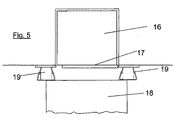
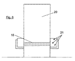
図5及び図6は、結合バッファ19の可能な取り付け状況及び衝突地点21で可能な車両の結合状況を例示的に示す。本発明は、可動なU字形部材2の衝突地点21によって公知の技術手段に比べて明らかに多い自由度を有し、より良好な条件が提供される場合、建物の損傷−連結構造中の二次応力−を回避することが分かる。
2 U字形部材
3 緩衝要素
4 脚部
5 脚部
6 脚部
7 脚部
8 基板
9 底面
10 ローラ軸受
11 取り外し可能な連結部材
12 積載ランプ
13 衝突地点
14 衝突地点
15 衝突地点
16 積替ブリッジ
17 キャリッジ又はフラップ開口部
18 荷台
19 結合バッファ
20 出入口
21 衝突地点
Claims (4)
- 衝撃に強い硬い材料から成る一方のU字形部材(1)と衝撃に強い硬い材料から成る他方のU字形部材(2)との間に弾性緩衝要素(3)を有し、ランプ又は積荷置場及び積替ブリッジに取り付けるための結合バッファであって、前記一方のU字形部材(1)の2つの脚部(6;7)と前記他方のU字形部材(2)の2つの脚部(4;5)とが、隣接しかつ互いに相対可動に配置されている当該結合バッファにおいて、
衝突負荷がかかっていない状態では、前記他方のU字形部材(2)の両脚部(4;5)の各々が、底面(9)に対して90°から反れた角度(α)を成して指向されていて、前記一方のU字形部材(1)の両脚部(6;7)の各々が、基板(8)に対して90°から反れた、前記の底面(9)に対して90°から反れた角度(α)に等しい角度(β)を成して指向されていて、かつ、前記他方のU字形部材(2)の両脚部(4;5)の開口幅が、前記一方のU字形部材(1)の両脚部(6;7)の開口幅より大きい配置で、前記他方のU字形部材(2)の両脚部(4;5)が、前記一方のU字形部材(1)の両脚部(6;7)を挟持すること、
衝突負荷がかかっている状態では、前記他方のU字形部材(2)の両脚部(4;5)と前記一方のU字形部材(1)の両脚部(6;7)とが隣接した部分に支点が存在することによって、当該挟持状態が維持されていること、及び
前記他方のU字形部材(2)の片側に負荷がかかる時に、この他方のU字形部材(2)の両脚部(4;5)と前記一方のU字形部材(1)の両脚部(6;7)とが、左右非対称に嵌合していることを特徴とする結合バッファ。 - 前記一方のU字形部材(1)の両脚部(6;7)は、前記基板(8)上に溶接されている結果、この一方のU字形部材(1)を形成することを特徴とする請求項1に記載の結合バッファ。
- 前記結合バッファは、取り外し可能な連結部(11)によってランプ(12)の前記基板(8)に取り付けられていることを特徴とする請求項1又は2に記載の結合バッファ。
- 支持装置又は支持板若しくは格子が、前記一方のU字形部材(1)の下端部に配置されていることを特徴とする請求項1〜3のいずれか1項に記載の結合バッファ。
Applications Claiming Priority (3)
| Application Number | Priority Date | Filing Date | Title |
|---|---|---|---|
| DE10358041A DE10358041B3 (de) | 2003-12-05 | 2003-12-05 | Andockpuffer |
| DE10358041.7 | 2003-12-05 | ||
| PCT/DE2004/002489 WO2005056442A1 (de) | 2003-12-05 | 2004-11-05 | Andockpuffer |
Publications (3)
| Publication Number | Publication Date |
|---|---|
| JP2007513030A JP2007513030A (ja) | 2007-05-24 |
| JP2007513030A5 JP2007513030A5 (ja) | 2011-01-27 |
| JP5208422B2 true JP5208422B2 (ja) | 2013-06-12 |
Family
ID=34399709
Family Applications (1)
| Application Number | Title | Priority Date | Filing Date |
|---|---|---|---|
| JP2006541791A Expired - Fee Related JP5208422B2 (ja) | 2003-12-05 | 2004-11-05 | 結合バッファ |
Country Status (11)
| Country | Link |
|---|---|
| US (1) | US7476433B2 (ja) |
| EP (1) | EP1692062B1 (ja) |
| JP (1) | JP5208422B2 (ja) |
| CN (1) | CN1890165B (ja) |
| AT (1) | ATE375949T1 (ja) |
| AU (1) | AU2004296922B2 (ja) |
| CA (1) | CA2547622A1 (ja) |
| DE (2) | DE10358041B3 (ja) |
| ES (1) | ES2295952T3 (ja) |
| NZ (1) | NZ548245A (ja) |
| WO (1) | WO2005056442A1 (ja) |
Families Citing this family (10)
| Publication number | Priority date | Publication date | Assignee | Title |
|---|---|---|---|---|
| FR2883946B1 (fr) * | 2005-04-04 | 2011-04-01 | Gouillardon Gaudry | Module amortisseur de chocs et butoirs, notamment pour quais de chargement mettant en oeuvre de tels modules |
| WO2008137575A1 (en) * | 2007-05-03 | 2008-11-13 | Jonathon Hocut | Bump resistant pin tumbler lock |
| FR2917077B1 (fr) * | 2007-06-05 | 2010-03-12 | Expresso France | Niveleur de quai et procede de mise en oeuvre |
| US7695286B2 (en) | 2007-09-18 | 2010-04-13 | Delaware Capital Formation, Inc. | Semiconductor electromechanical contact |
| FR2956083B1 (fr) * | 2010-02-09 | 2012-03-16 | Lecapitaine | Dispositif de butee de vehicule automobile |
| US20140115868A1 (en) * | 2012-10-29 | 2014-05-01 | Gregory Ruhlander | Coupling System to Reduce Vibration |
| DE102013000075A1 (de) * | 2013-01-08 | 2014-07-10 | CATAC CAPITAL GmbH | Rammpuffer |
| US12037210B2 (en) * | 2017-08-04 | 2024-07-16 | DL Manufacturing, Inc. | Dock bumper having progressive spring rate |
| DE102017008542A1 (de) * | 2017-09-11 | 2019-03-14 | Süddeutsche Gelenkscheibenfabrik GmbH & Co. KG | Anfahrpuffer |
| EP3486200A1 (en) | 2017-11-16 | 2019-05-22 | Ideal Warehouse Innovations, Inc. | Loading dock bumper |
Family Cites Families (8)
| Publication number | Priority date | Publication date | Assignee | Title |
|---|---|---|---|---|
| JPS59100664U (ja) * | 1982-12-25 | 1984-07-07 | トヨタ自動車株式会社 | ステアリング装置のエネルギ−吸収部材 |
| CN85106779B (zh) * | 1985-08-31 | 1987-11-04 | 沈阳胶管厂 | 一种振冲橡胶减震器 |
| DE9201381U1 (de) * | 1992-02-05 | 1992-04-23 | Van Wijk Nederland B.V., Lelystad | Anfahrpuffer für Rampen |
| US5658633A (en) * | 1995-09-18 | 1997-08-19 | Frommelt Industries Of Canada Inc. | Loading dock bumpers |
| US6120871A (en) * | 1995-09-18 | 2000-09-19 | Frommelt Industries Of Canada Inc. | Loading dock bumpers |
| DE10040272C2 (de) | 2000-08-17 | 2003-08-14 | Santo Zuccaro | Rammpuffer |
| DE20115421U1 (de) * | 2001-09-18 | 2003-02-20 | Viering, Ulrich, 42369 Wuppertal | Energieabsorbierender Anfahrschutz |
| DE20310927U1 (de) * | 2003-07-16 | 2003-11-13 | Richter-Tore GmbH, 21224 Rosengarten | Anfahrpuffer modifiziert LKW-Rammschutz bei Verladerampen modifiziert |
-
2003
- 2003-12-05 DE DE10358041A patent/DE10358041B3/de not_active Expired - Fee Related
-
2004
- 2004-11-05 JP JP2006541791A patent/JP5208422B2/ja not_active Expired - Fee Related
- 2004-11-05 AU AU2004296922A patent/AU2004296922B2/en not_active Ceased
- 2004-11-05 AT AT04802706T patent/ATE375949T1/de active
- 2004-11-05 CN CN2004800359057A patent/CN1890165B/zh not_active Expired - Fee Related
- 2004-11-05 US US10/581,877 patent/US7476433B2/en not_active Expired - Fee Related
- 2004-11-05 DE DE502004005298T patent/DE502004005298D1/de not_active Expired - Lifetime
- 2004-11-05 WO PCT/DE2004/002489 patent/WO2005056442A1/de not_active Ceased
- 2004-11-05 EP EP04802706A patent/EP1692062B1/de not_active Expired - Lifetime
- 2004-11-05 NZ NZ548245A patent/NZ548245A/en unknown
- 2004-11-05 ES ES04802706T patent/ES2295952T3/es not_active Expired - Lifetime
- 2004-11-05 CA CA002547622A patent/CA2547622A1/en not_active Abandoned
Also Published As
| Publication number | Publication date |
|---|---|
| JP2007513030A (ja) | 2007-05-24 |
| WO2005056442A1 (de) | 2005-06-23 |
| CA2547622A1 (en) | 2005-06-23 |
| US20070161267A1 (en) | 2007-07-12 |
| AU2004296922A1 (en) | 2005-06-23 |
| HK1093954A1 (zh) | 2007-03-16 |
| EP1692062B1 (de) | 2007-10-17 |
| ATE375949T1 (de) | 2007-11-15 |
| CN1890165B (zh) | 2010-06-09 |
| CN1890165A (zh) | 2007-01-03 |
| AU2004296922B2 (en) | 2009-02-05 |
| NZ548245A (en) | 2010-03-26 |
| US7476433B2 (en) | 2009-01-13 |
| DE10358041B3 (de) | 2005-05-04 |
| EP1692062A1 (de) | 2006-08-23 |
| DE502004005298D1 (de) | 2007-11-29 |
| ES2295952T3 (es) | 2008-04-16 |
Similar Documents
| Publication | Publication Date | Title |
|---|---|---|
| JP5208422B2 (ja) | 結合バッファ | |
| US10563360B2 (en) | Finger joint with a bridging cover plate | |
| JP2007513030A5 (ja) | ||
| RU2385250C2 (ru) | Трейлерная система для инспектирования транспортных средств и система контроля для нее | |
| CN110831881B (zh) | 用于电梯系统中旋转平台的支撑装置 | |
| RU2643115C2 (ru) | Соединительная конструкция и железнодорожный мост с такой соединительной конструкцией | |
| KR101530966B1 (ko) | 레일과의 접촉부를 강화한 가이드플레이트를 구비하는 레일 체결장치 | |
| US9745152B2 (en) | Impact buffer | |
| CN105263848A (zh) | 用于起重机臂铰链的轨道 | |
| JP2001158585A (ja) | 乗客コンベア装置 | |
| US8061698B2 (en) | Geometric shaped side bearing pad | |
| AU700311B2 (en) | A window stay | |
| KR20010075908A (ko) | 레일의 열팽창을 고려한 교량점검차용 주행장치 | |
| CN112004771B (zh) | 桥式起重机布置 | |
| CA2647977C (en) | Test device | |
| TW202446691A (zh) | 行走限制裝置 | |
| KR102690129B1 (ko) | 교량거더용 클램핑 구조를 포함하는 레일 체결 시스템 | |
| KR100506789B1 (ko) | 엘리베이터용 양방향 비상 정지장치 | |
| WO2024022698A1 (en) | Structural vibration damper | |
| US6981575B2 (en) | Concrete rail safety device for an elevator car | |
| CN223456003U (zh) | 挂载式机器人防撞缓冲结构 | |
| KR200498215Y1 (ko) | 교량거더용 클램핑 조립체 | |
| JP2002265015A (ja) | 自動倉庫 | |
| JP2002154761A (ja) | 非鉄製ガイドレール用安全装置 | |
| EP1488978A1 (en) | Side bearer |
Legal Events
| Date | Code | Title | Description |
|---|---|---|---|
| A621 | Written request for application examination |
Free format text: JAPANESE INTERMEDIATE CODE: A621 Effective date: 20070824 |
|
| RD04 | Notification of resignation of power of attorney |
Free format text: JAPANESE INTERMEDIATE CODE: A7424 Effective date: 20100526 |
|
| A131 | Notification of reasons for refusal |
Free format text: JAPANESE INTERMEDIATE CODE: A131 Effective date: 20100803 |
|
| A601 | Written request for extension of time |
Free format text: JAPANESE INTERMEDIATE CODE: A601 Effective date: 20101102 |
|
| A602 | Written permission of extension of time |
Free format text: JAPANESE INTERMEDIATE CODE: A602 Effective date: 20101110 |
|
| A524 | Written submission of copy of amendment under article 19 pct |
Free format text: JAPANESE INTERMEDIATE CODE: A524 Effective date: 20101202 |
|
| A131 | Notification of reasons for refusal |
Free format text: JAPANESE INTERMEDIATE CODE: A131 Effective date: 20110712 |
|
| A601 | Written request for extension of time |
Free format text: JAPANESE INTERMEDIATE CODE: A601 Effective date: 20111011 |
|
| A602 | Written permission of extension of time |
Free format text: JAPANESE INTERMEDIATE CODE: A602 Effective date: 20111018 |
|
| A521 | Request for written amendment filed |
Free format text: JAPANESE INTERMEDIATE CODE: A523 Effective date: 20111110 |
|
| A131 | Notification of reasons for refusal |
Free format text: JAPANESE INTERMEDIATE CODE: A131 Effective date: 20120522 |
|
| A521 | Request for written amendment filed |
Free format text: JAPANESE INTERMEDIATE CODE: A523 Effective date: 20120820 |
|
| TRDD | Decision of grant or rejection written | ||
| A01 | Written decision to grant a patent or to grant a registration (utility model) |
Free format text: JAPANESE INTERMEDIATE CODE: A01 Effective date: 20130212 |
|
| A61 | First payment of annual fees (during grant procedure) |
Free format text: JAPANESE INTERMEDIATE CODE: A61 Effective date: 20130220 |
|
| FPAY | Renewal fee payment (event date is renewal date of database) |
Free format text: PAYMENT UNTIL: 20160301 Year of fee payment: 3 |
|
| R150 | Certificate of patent or registration of utility model |
Free format text: JAPANESE INTERMEDIATE CODE: R150 |
|
| LAPS | Cancellation because of no payment of annual fees |