JP5205272B2 - Pneumatic tire - Google Patents
Pneumatic tire Download PDFInfo
- Publication number
- JP5205272B2 JP5205272B2 JP2008539896A JP2008539896A JP5205272B2 JP 5205272 B2 JP5205272 B2 JP 5205272B2 JP 2008539896 A JP2008539896 A JP 2008539896A JP 2008539896 A JP2008539896 A JP 2008539896A JP 5205272 B2 JP5205272 B2 JP 5205272B2
- Authority
- JP
- Japan
- Prior art keywords
- tire
- carcass
- bead core
- bead
- radial direction
- Prior art date
- Legal status (The legal status is an assumption and is not a legal conclusion. Google has not performed a legal analysis and makes no representation as to the accuracy of the status listed.)
- Active
Links
Images


Classifications
-
- B—PERFORMING OPERATIONS; TRANSPORTING
- B60—VEHICLES IN GENERAL
- B60C—VEHICLE TYRES; TYRE INFLATION; TYRE CHANGING; CONNECTING VALVES TO INFLATABLE ELASTIC BODIES IN GENERAL; DEVICES OR ARRANGEMENTS RELATED TO TYRES
- B60C15/00—Tyre beads, e.g. ply turn-up or overlap
- B60C15/0009—Tyre beads, e.g. ply turn-up or overlap features of the carcass terminal portion
- B60C15/0027—Tyre beads, e.g. ply turn-up or overlap features of the carcass terminal portion with low ply turn-up, i.e. folded around the bead core and terminating at the bead core
-
- B—PERFORMING OPERATIONS; TRANSPORTING
- B60—VEHICLES IN GENERAL
- B60C—VEHICLE TYRES; TYRE INFLATION; TYRE CHANGING; CONNECTING VALVES TO INFLATABLE ELASTIC BODIES IN GENERAL; DEVICES OR ARRANGEMENTS RELATED TO TYRES
- B60C15/00—Tyre beads, e.g. ply turn-up or overlap
-
- B—PERFORMING OPERATIONS; TRANSPORTING
- B60—VEHICLES IN GENERAL
- B60C—VEHICLE TYRES; TYRE INFLATION; TYRE CHANGING; CONNECTING VALVES TO INFLATABLE ELASTIC BODIES IN GENERAL; DEVICES OR ARRANGEMENTS RELATED TO TYRES
- B60C15/00—Tyre beads, e.g. ply turn-up or overlap
- B60C15/06—Flipper strips, fillers, or chafing strips and reinforcing layers for the construction of the bead
-
- Y—GENERAL TAGGING OF NEW TECHNOLOGICAL DEVELOPMENTS; GENERAL TAGGING OF CROSS-SECTIONAL TECHNOLOGIES SPANNING OVER SEVERAL SECTIONS OF THE IPC; TECHNICAL SUBJECTS COVERED BY FORMER USPC CROSS-REFERENCE ART COLLECTIONS [XRACs] AND DIGESTS
- Y10—TECHNICAL SUBJECTS COVERED BY FORMER USPC
- Y10T—TECHNICAL SUBJECTS COVERED BY FORMER US CLASSIFICATION
- Y10T152/00—Resilient tires and wheels
- Y10T152/10—Tires, resilient
- Y10T152/10495—Pneumatic tire or inner tube
- Y10T152/10855—Characterized by the carcass, carcass material, or physical arrangement of the carcass materials
Abstract
Description
この発明は、ビードコアを埋設した一対のビード部、ビード部からタイヤ径方向外側に延びる一対のサイドウォール部、及び両サイドウォール間にまたがって延びるトレッド部の各部にわたってトロイド状に延びる本体部と、この本体部から延び、ビードコアの周りにタイヤ幅方向内側から外側に向かって折り返された折返し部とからなる少なくとも一枚のプライで構成されるカーカスを具える空気入りタイヤに関するものであり、かかるビード部の耐久性を向上させる。 The present invention includes a pair of bead portions in which a bead core is embedded, a pair of sidewall portions extending outward in the tire radial direction from the bead portion, and a main body portion extending in a toroid shape over each portion of a tread portion extending between both sidewalls, The present invention relates to a pneumatic tire including a carcass formed of at least one ply extending from the main body portion and folded around the bead core from the inner side to the outer side in the tire width direction. Improves part durability.
従来の空気入りタイヤにおいては、図1に示すように、図示しないトレッド部からサイドウォール部を経てビード部101までトロイド状に延びる少なくとも一枚のカーカス105を、ビード部101に埋設したビードコア102に沿って、タイヤ幅方向内側から外側へ折り返して係止することが一般的であり、このようなビード部構造の下では、リム組みしたタイヤの負荷転動時に、リムフランジよりタイヤ径方向外側のビード部101が、タイヤ幅方向外側へ繰返し倒れ込み変形することに起因して、倒れ込み変形するカーカス部分及び折返し端部106に応力が集中してゴムとカーカス105の間にクラックが発生し、倒れ込み変形するカーカス部分及び折返し端部106がゴムとセパレーションし易くなる。また、タイヤが負荷転動する場合には、カーカス105にタイヤ径方向外側への引張力が作用するため、ビード部102への係止力が不十分な場合には、カーカス105のビード部102からの引き抜けが発生し易くなる。
In a conventional pneumatic tire, as shown in FIG. 1, at least one
そこで、このような折返し端部のゴムとのセパレーションを防止すべく、例えば特開2001−191758号公報では、タイヤ負荷転動時に倒れ込み変形し、応力が集中し易いビード部領域に剛性を高める補強層を設けることにより、ビード部の倒れ込みを抑制して、カーカスとゴムとのセパレーションの発生を防止することが提案されている。また、特開平9−156310号公報では、カーカスをビードコアの周りに巻付けることで、カーカスの折返し端部をビード部の歪みの少ない領域に配置させ、折返し端部からのクラックの発生を防止するとともに、ビードコアへのカーカスの巻付けが、タイヤが負荷転動する際に、カーカスのタイヤ径方向外側への引張力に抗する係止力となり、カーカスのビード部からの引き抜けを発生しにくくすることが提案されている。 Therefore, in order to prevent such separation from the folded end rubber, for example, in Japanese Patent Application Laid-Open No. 2001-191758, a reinforcement that increases the rigidity in the bead portion region where the tire falls and deforms when the tire is loaded and the stress is easily concentrated. It has been proposed to prevent the occurrence of separation between the carcass and the rubber by providing a layer to suppress the falling of the bead portion. Further, in Japanese Patent Laid-Open No. 9-156310, the carcass is wound around the bead core so that the folded end portion of the carcass is disposed in a region where the distortion of the bead portion is small, and the occurrence of cracks from the folded end portion is prevented. At the same time, the winding of the carcass around the bead core becomes a locking force that resists the pulling force of the carcass outward in the radial direction of the tire when the tire rolls, and the carcass is less likely to be pulled out from the bead portion. It has been proposed to do.
特開2001−191758号公報に記載の発明においては、ビード部の倒れ込み変形を抑制して、ビード部におけるカーカスとゴムとのセパレーションを有効に防止してはいる。しかし出願人は、特にカーカスに高い引張力の作用する重荷重用タイヤを使用する際などに、カーカスのタイヤ径方向外側への引張力に抵抗する係止力を更に向上させるものを考案した。特開平9−156310号公報に記載の発明においては、カーカスの折返し端部からのクラックの発生を防止することはできるが、倒れ込み変形するカーカス部分でのセパレーションが発生し、また特には重荷重用タイヤでは係止力が不足する虞がある。 In the invention described in Japanese Patent Application Laid-Open No. 2001-191758, the falling deformation of the bead portion is suppressed to effectively prevent the separation of the carcass and the rubber in the bead portion. However, the applicant has devised one that further improves the locking force that resists the pulling force of the carcass on the outer side in the tire radial direction, particularly when using a heavy duty tire in which a high pulling force acts on the carcass. In the invention described in Japanese Patent Application Laid-Open No. 9-156310, the occurrence of cracks from the folded end portion of the carcass can be prevented, but separation occurs in the carcass portion that collapses and deforms, and in particular, a heavy duty tire Then, there is a possibility that the locking force is insufficient.
この発明は、そのような問題点を解決するものであり、補強層の構成の適正化を図ることにより、カーカスとゴムとのセパレーションを防止するとともに、カーカスのビード部からの引き抜けも充分に防止してビード部の耐久性を向上させた空気入りタイヤを提供することを目的とする。 The present invention solves such a problem, and by optimizing the configuration of the reinforcing layer, it prevents separation of the carcass and rubber and sufficiently pulls out the carcass from the bead portion. An object of the present invention is to provide a pneumatic tire which is prevented to improve the durability of the bead portion.
上記の目的を達成するため、この発明は、ビードコアを埋設した一対のビード部、ビード部からタイヤ径方向外側に延びる一対のサイドウォール部、及び両サイドウォール部間にまたがって延びるトレッド部の各部にわたってトロイド状に延びる本体部と、この本体部から延び、ビードコアの周りにタイヤ幅方向内側から外側に向かって折り返された折返し部とからなる少なくとも一枚のプライで構成されるカーカスを具える空気入りタイヤにおいて、実質的にタイヤ周方向に沿って延びるコードをゴム被覆してなる補強層を少なくとも二層、ビードコアのタイヤ幅方向内側で、カーカスの内面に沿って配設していることを特徴とする空気入りタイヤである。かかる構成により、ビード部における倒れ込み変形を抑制し、カーカスとゴムとのセパレーシヨンを防止するとともに、カーカスが補強層とビードコアとの間に挟まれるように配置することで、カーカスのタイヤ径方向外側への引張力に抗する係止力を向上させ、カーカスのビード部近傍からの引き抜けの可能性を大幅に低減することが可能となる。ここで「実質的にタイヤ周方向」とは、一本のコードを螺旋状に連続巻回して補強層を形成する場合等、生産上不可避的に発生する微小な傾きも含むことを意味するものである。 In order to achieve the above object, the present invention includes a pair of bead portions in which a bead core is embedded, a pair of sidewall portions extending outward in the tire radial direction from the bead portion, and a tread portion extending between both sidewall portions. An air having a carcass composed of at least one ply including a main body extending in a toroidal shape and a folded portion extending from the main body and folded back around the bead core from the inner side to the outer side in the tire width direction. In the contained tire, at least two reinforcing layers formed by rubber-covering cords extending substantially along the tire circumferential direction are disposed along the inner surface of the carcass inside the bead core in the tire width direction. It is a pneumatic tire. With such a configuration, the deformation of the bead portion is suppressed, the separation of the carcass and the rubber is prevented, and the carcass is arranged so as to be sandwiched between the reinforcing layer and the bead core, so that the outer side of the carcass in the tire radial direction is arranged. It is possible to improve the locking force that resists the pulling force to the carcass and greatly reduce the possibility of pulling out from the vicinity of the bead portion of the carcass. Here, “substantially the tire circumferential direction” means including a slight inclination that is inevitably generated in production, such as when a reinforcing layer is formed by continuously winding a single cord in a spiral shape. It is.
また、補強層を構成するコードは金属コード又は有機繊維コードであることが好ましい。 Further, the cord constituting the reinforcing layer is preferably a metal cord or an organic fiber cord.
更に、補強層のタイヤ径方向外側の端部は、ビードコアのタイヤ径方向最外端よりもタイヤ径方向外側にあることが好ましい。ここで「ビードコアのタイヤ径方向最外端」とは、ビードコアのタイヤ径方向における最も外側の位置を言うものとする。 Furthermore, it is preferable that the end portion of the reinforcing layer on the outer side in the tire radial direction is on the outer side in the tire radial direction of the outermost end in the tire radial direction of the bead core. Here, “the outermost end in the tire radial direction of the bead core” refers to the outermost position of the bead core in the tire radial direction.
更にまた、補強層のタイヤ径方向内側の端部は、ビードコアのタイヤ径方向最内端よりもタイヤ径方向内側にあることが好ましい。ここで「ビードコアのタイヤ径方向最内端」とは、ビードコアのタイヤ径方向における最も内側の位置を言うものとする。 Furthermore, it is preferable that the end portion of the reinforcing layer on the inner side in the tire radial direction is on the inner side in the tire radial direction than the innermost end in the tire radial direction of the bead core. Here, “the innermost end of the bead core in the tire radial direction” refers to the innermost position of the bead core in the tire radial direction.
加えて、補強層はビードコアのタイヤ径方向内側位置を通ることが好ましく、また、補強層のタイヤ径方向内側の端部は、カーカスの折返し端部よりもタイヤ径方向外側にあることがより好ましい。 In addition, the reinforcing layer preferably passes through the inner position in the tire radial direction of the bead core, and the end portion in the tire radial direction of the reinforcing layer is more preferably located on the outer side in the tire radial direction than the folded end portion of the carcass. .
加えてまた、折返し部の折返し端部はビードコアから離間していることが好ましい。 In addition, the folded end portion of the folded portion is preferably separated from the bead core.
また、カーカスの折返し部の全体をビードコアに沿わせて折り返すことが好ましい。このとき、カーカスの折返し部を塑性的に折り返すことが好ましい。 Further, it is preferable that the entire folded portion of the carcass is folded along the bead core. At this time, it is preferable to plastically fold the folded portion of the carcass.
更に、隣接する二層の補強層をタイヤ径方向にずらして配設していることが好ましい。ここで、「隣接する二層の補強層をタイヤ径方向にずらして」とは、補強層の接線方向に垂直な同一仮想線上に、隣接する補強層のコードの中心位置が同時に存在しないことを言うものとする。 Furthermore, it is preferable that the two adjacent reinforcing layers are arranged while being shifted in the tire radial direction . Here, “shifting two adjacent reinforcing layers in the tire radial direction ” means that the center positions of the cords of adjacent reinforcing layers do not exist simultaneously on the same imaginary line perpendicular to the tangential direction of the reinforcing layer. Say it.
更にまた、補強層のコードの打ち込み密度が、補強層のタイヤ径方向外側端部分にて、その他の部分に比べ小さくなっていることが好ましい。 Furthermore, it is preferable that the cord driving density of the reinforcing layer is smaller at the outer end portion in the tire radial direction of the reinforcing layer than at other portions.
加えて、補強層のコードの打ち込み密度が、補強層のタイヤ径方向外側端から、ビードコアのタイヤ幅方向最内端のタイヤ幅方向内側位置に向かって徐々に大きくなることが好ましい。ここで「ビードコアのタイヤ幅方向最内端」とは、ビードコアのタイヤ幅方向における最も内側の位置を言うものとする。 In addition, it is preferable that the cord driving density of the reinforcing layer gradually increases from the outer end in the tire radial direction of the reinforcing layer toward the inner side in the tire width direction of the innermost end of the bead core in the tire width direction. Here, “the innermost end of the bead core in the tire width direction” refers to the innermost position of the bead core in the tire width direction.
加えてまた、補強層は、タイヤ幅方向に見て、ビードコアが存在する区間にて2層となっており、その他の区間にて1層となっていることが好ましい。なお、ここでいう「ビードコアが存在する区間」とは、挟み込みによりカーカスの引き抜け防止の効果が特に大きい区間であり、図8に示す区間Xをいうものとする。 In addition, it is preferable that the reinforcing layer has two layers in the section where the bead core exists and one layer in the other sections when viewed in the tire width direction. Here, the “section where the bead core exists” is a section in which the effect of preventing the carcass from being pulled out due to pinching is particularly large, and refers to the section X shown in FIG.
この発明によれば、ビード部に複数枚の補強層を適切な構成で設けることにより、カーカスとゴムとのセパレーションを防止するとともに、カーカスのビード部からの引き抜けも充分に防止してビード部の耐久性を向上させることができる空気入りタイヤを提供することが可能となる。 According to this invention, by providing a plurality of reinforcing layers in the bead portion with an appropriate configuration, separation of the carcass and the rubber is prevented, and the bead portion is sufficiently prevented from being pulled out from the bead portion. It is possible to provide a pneumatic tire capable of improving the durability of the tire.
1 ビード部
2 ビードコア
3 本体部
4 折返し部
5 カーカス
6 折返し端部
7 コード
8 補強層
X ビードコアが存在する区間DESCRIPTION OF SYMBOLS 1
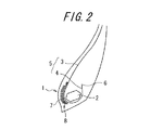
以下、図面を参照しつつこの発明の実施の形態を説明する。図2はこの発明に従う空気入りタイヤ(以下「タイヤ」という。)のビード部のタイヤ幅方向断面図である。 Hereinafter, embodiments of the present invention will be described with reference to the drawings. FIG. 2 is a sectional view in the tire width direction of a bead portion of a pneumatic tire (hereinafter referred to as “tire”) according to the present invention.
図2に示すタイヤのビード部1は、ビードコア2を埋設した一対のビード部1(図には一方のビード部1のみを示す)と、ビード部からタイヤ径方向外側に延びる一対のサイドウォール部、及び両サイドウォール間にまたがって延びるトレッド部の各部にわたってトロイド状に延びる本体部3と、この本体部3から延び、ビードコア2の周りにタイヤ幅方向内側から外側に向かって折り返された折返し部4とからなるプライで構成されるカーカス5を具えている。この態様では、折返し部4の折返し端部6はビードコア2から離間するように配設されている。また、略タイヤ周方向に沿って延びるコード7をゴム被覆してなる二層の補強層8を、ビードコア2のタイヤ幅方向内側で、カーカス5の内面に沿って配設している。このとき、二層の補強層8はタイヤ負荷転動時に倒れ込み変形を起こし易い部分に配設されることから、倒れ込み変形が抑制され、カーカス5とゴムとのセパレーシヨンが防止される。また、ビードコア2と補強層8でカーカス5を挟み込むように補強層8を配設することから、挟み込みの効果によりカーカス5のビード部1における係止力が向上し、カーカス5のビード部1からの引き抜けを強く抑制することが可能となる。なお、タイヤ負荷転動時に補強層8が動き易いと、タイヤ負荷転動時などに補強層8が動くことに伴いビードコア2との間のカーカス5も動いてしまうので、カーカス5が充分に固定されずに、ビードコア2と補強層8とによる挟み込みによるカーカス5の係止力が低下し、カーカス5のビード部1からの引き抜けを有効に抑制することができない。上記構成では、補強層8を二層とすることで、隣接する補強層8のコード7同士が相互に動きを拘束し合っているので、タイヤ負荷転動時の倒れ込み変形をより強く抑制するだけではなく、動きが拘束された補強層8によりカーカス5が強く挟み込まれ、カーカス5のビード部1への係止力が充分に確保され、カーカス5の引き抜けが有効に抑制される。また、補強層8のコード7とカーカス5のコードとが直交する方向に隣接して配設されていることから、カーカス5に引張力が働く際には、補強層8のコード7が引っ掛かりとなって係止力が向上するので、引き抜け防止効果を向上させることとなる。重荷重用タイヤのカーカス5には高い引張力が作用するので、かかるタイヤに上記構成を採用することが特には有利である。
The bead portion 1 of the tire shown in FIG. 2 includes a pair of bead portions 1 in which a
更に、補強層8を構成するコード7は要求される重量、剛性等に応じて金属コード又は有機繊維コードであることが好ましい。なぜなら、車種に応じて充分な柔軟性及び強度を具えたコード7が用いられない場合には、タイヤ負荷転動時に、倒れ込み変形を充分に抑制することができなくなり、カーカス5とゴムとのセパレーションが発生し易くなるとともに、カーカス5のビード部1への係止力が充分に向上されずに、カーカス5のビード部1からの引き抜けも充分に防止することができなくなる可能性があるからである。例えば、乗用車用タイヤにおける補強層8を構成するコード7は、それ程高い剛性を必要としないことから、むしろ重量を軽くすることが重要となり、一般に剛性はそれほど高くないが単位体積当たりの重量が比較的小さい特性を有する有機繊維コードを用いることが好ましいが、バス、トラック、農業機械、建設車両等に用いられる重荷重用タイヤにおける補強層8を構成するコード7は、高い剛性を必要とすることから、一般に単位体積当たりの重量は大きいが剛性が高い特性を有する金属コードとすることが好ましい。なお、金属コードとしては、例えば、単線からなるスチールコード、複数線を撚ったスチールコード等を、有機繊維コードとしては、例えば、レーヨンコード、アラミド(芳香族ポリアミド)コード等を用いることが好ましい。また、ビード部1を構成するゴムの種類、ビードコア2の剛性や断面形状等に応じて、コード7の寸法を適宜変更することが可能である。
Furthermore, the
更にまた、補強層8のタイヤ径方向外側の端部は、ビードコア2のタイヤ径方向最外端よりもタイヤ径方向外側にあることが好ましい。なぜなら、補強層8のタイヤ径方向外側の端部がビードコア2のタイヤ径方向最外端よりもタイヤ径方向内側にある場合には、ビードコア2のタイヤ径方向最外端近傍における倒れ込み変形を充分に防止することができずに、倒れ込み変形した際に、ビードコア2のタイヤ径方向最外端に応力が集中し、ビードコア2とゴムとのセパレーションが発生し易くなる可能性があるからである。
Furthermore, it is preferable that the end portion of the reinforcing
加えて、補強層8のタイヤ径方向内側の端部は、ビードコアのタイヤ径方向最内端よりもタイヤ径方向内側にあることが好ましい。なぜなら、補強層8のタイヤ径方向内側の端部がビードコア2のタイヤ径方向最内端よりもタイヤ径方向内側にあることにより、ビードコア2と補強層8でカーカス5を挟み込む領域が増加し、挟み込みの効果が向上するので、カーカス5の引き抜けがより発生しにくくなる可能性があるからである。
In addition, the end of the reinforcing
加えてまた、図4に示すように、補強層8はビードコア2のタイヤ径方向内側位置、すなわちビード装着姿勢にてビードコア2とリムフランジに挟まれる領域を通ることが好ましい。なぜなら、例え一部であっても補強層8がビードコア2とリムフランジに挟まれる領域を通ることにより、リムフランジとビードコア2の間に補強層8が強く挟み込まれ、その強く挟み込まれている補強層の領域がカーカス5をビードコア2と挟み込むこととなり、カーカス5のビード部1への係止力が向上するので、カーカス5のビード部1からの引き抜けがより発生しにくくなる可能性があるからである。また、補強層8がビードコア2のタイヤ径方向内側位置を通り、カーカスに沿って更に延在した補強層8のタイヤ径方向内側の端部が、カーカス5の折返し端部6よりもタイヤ径方向外側にあることが好ましい。なぜなら、補強層8がビードコア2のタイヤ径方向内側位置を通り、カーカスに沿って更に延在した補強層8のタイヤ径方向内側の端部が、カーカス5の折返し端部6よりもタイヤ径方向外側にあることにより、カーカス5の折返し端部6に応力が集中しにくくなるので、折返し端部6とゴムとのクラックが発生せずに、カーカス5とゴムとのセパレーションが防止される可能性があるからである。
In addition, as shown in FIG. 4, it is preferable that the reinforcing
また、この発明に従うその他の構成を具えることにより、カーカス5の引き抜けを充分に防止しているタイヤにおいては、図2に示すように、折返し部4の折返し端部6はビードコア2から離間していることが好ましい。なぜなら、カーカス5をビードコア2の周りに巻付けることで、カーカス5の折返し端部6をビード部1の歪みの少ない領域に配置させ、折返し端部6からのクラックの発生を防止するとともに、ビードコア2へのカーカス5の巻付けが、タイヤが負荷転動する際に、カーカス5のタイヤ径方向外側への引張力に抗する係止力となり、カーカス5のビード部1からの引き抜けを発生しにくくするが、カーカス5をビードコア2に巻き付ける工程は、折返し端部6をより長くビードコア2に沿わせて折り曲げることから、ビードコア2に巻き付けない場合に比べ、折り曲げ操作にかかる時間が長くなり、製造工程も複雑化するので、加硫成形に至るまでに時間と人手を要し、省力化、省人化にそぐわなくなり、タイヤの生産性を損なう場合があるからである。
In addition, in the tire that sufficiently prevents the
更に、この発明に従うその他の構成を具えていても、カーカス5の引き抜けが未だ充分に防止されていないタイヤにおいては、図3に示すように、カーカス5の折返し部4の全体をビードコア2に沿わせて折り返すことが好ましい。なぜなら、折返し部4全体をビードコア2に沿わせて折り返すことにより、リム組みしたタイヤの負荷転動時に、ビード部1がタイヤ幅方向外側へ倒れ込み変形しても、折返し端部6に応力が集中することなく、ゴムと折返し端部6の間がクラックする可能性が低減するので、カーカス5がゴムとセパレーションしにくくなるとともに、カーカス5をビードコア2に巻き付けることにより引張応力に抗する係止力が向上することから、カーカス5のビード部1からの引き抜けが更に発生しにくくなる可能性があるからである。また、このとき、カーカス5の折返し部4をビードコア2に沿って塑性的に折り返すことが好ましい。なぜなら、塑性的に折り返すことにより、弾性的に折り返す場合に比べ、カーカス5の折返し部4がビードコア2とより合致した形状となり、カーカス5の折返し部4とビードコア2との離間距離が全体に小さくなるので、カーカス5の折返し部4がビードコア2に強く係止されることとなり、カーカス5のタイヤ径方向外側への引張力に抵抗する係止力が更に向上し、カーカス5のビード部1からの引き抜けがより一層抑制されるからである。
Further, in the tire in which the
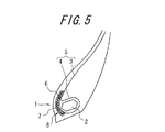
更にまた、図5に示すように、隣接する二層の補強層8をずらして配設することが好ましい。すなわち、補強層8の接線方向に垂直な同一仮想線上に、隣接する補強層8のコード7の中心位置が同時に存在しないことが好ましい。なぜなら、補強層8を構成するコード7がかかる同一仮想線上に中心位置が同時に存在する場合には、コード7が充分密に配設されないことから、補強層8はビード部1の倒れ込み変形を防止するために必要な剛性を充分に確保することができなくなり、カーカス5とゴムとのセパレーション及びカーカス5の引き抜けが発生し易くなる可能性があるからである。また、例え隣接する二層の補強層8がずれて配設されていても、かかる二層間の距離が離れすぎていてはビード部1の剛性を充分に確保することができずに、カーカス5とゴムとのセパレーション及びカーカス5の引き抜けを抑制する効果が低減する可能性がある。
Furthermore, as shown in FIG. 5, it is preferable to dispose the two adjacent reinforcing
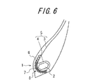
加えて、図6に示すように、補強層8のコード7の打ち込み密度が、補強層8のタイヤ径方向外側端部分にて、その他の部分に比べ小さくなっていることが好ましい。タイヤ内の圧力によりビード部1をタイヤ幅方向内側から外側に押圧する力が働くことから、少なくともビードコア2のタイヤ幅方向内側にあるカーカス部分を、打ち込み密度の大きなコード7を有する補強層部分とビードコア2とで挟み込めば、カーカス5が強く挟み込まれ、カーカス5の引き抜けを防止することができる。一方、補強層8のタイヤ径方向外側にあるコード7程、ビードコア2から離間しており、かかる離間した位置に補強層8を配設しても、挟み込みによる効果が小さく、補強層8のタイヤ径方向外側端にあるコード7の打ち込み密度を小さくしても、カーカス5の挟み込みに大きく影響しない。そのことから、補強層8のタイヤ径方向外側端部分のコード7の打ち込み密度を小さくして、補強層8のタイヤ径方向外側端部分におけるカーカス5への応力集中を抑制しつつも、ビード部1の耐久性を向上させ、併せて重量の増加を抑制することができる。なお、このとき、上記した構成の範囲内であれば、補強層8のコード7の打ち込み密度を少なくとも一部を不均一としてもよい。また、図示していないが、二層の補強層の打ち込み密度を夫々異ならせることもできる。このとき、ビード部1との挟み込みによる効果が大きなカーカス側にある補強層8の打ち込み密度を大きくすることが好ましい。
In addition, as shown in FIG. 6, it is preferable that the driving density of the
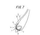
加えてまた、図7に示すように、補強層8のコードの打ち込み密度が、補強層8のタイヤ径方向外側端から、ビードコア2のタイヤ幅方向最内端のタイヤ幅方向内側位置に向かって徐々に迄大きくなることが好ましい。なぜなら、ビードコア2のタイヤ幅方向最内端のタイヤ幅方向内側位置に近いほどビードコア2と補強層8との離間距離が小さくなり、その間に挟みこまれるカーカス5が強く挟み込まれるので、ビードコア2のタイヤ幅方向最内端のタイヤ幅方向内側位置に向かって補強層8のコード7の打ち込み密度を徐々に大きくすると、打ち込み密度の大きなコード7を有する補強層部分とビードコア2とによりカーカス5を強く挟み込むことができ、カーカス5のビード部1からの引き抜けを有効に抑制することが可能となるからである。また、補強層8からタイヤ径方向外側に離間した位置にあるコード7程打ち込み密度が小さくなっているので、カーカス5への応力集中を抑制しつつも、ビード部1の耐久性を向上させ、併せて重量の増加を抑制することが可能となるからである。
In addition, as shown in FIG. 7, the cord driving density of the reinforcing
また、図8に示すように、補強層8は、タイヤ幅方向に見て、ビードコア2が存在する区間Xにて2層となっており、その他の区間にて1層となっていることが好ましい。タイヤ内の圧力によりビード部1をタイヤ幅方向内側から外側へと押圧する力が働くことから、かかる区間Xにある補強層8のみを2層とし、カーカス5をビードコア2とで挟み込んでも、カーカス5のビード部1への係止力を充分に確保することができるので、カーカス5のビード部1からの引き抜けを有効に抑制することが可能である。また、上述の区間X以外の区間の補強層5を一層とすることで、カーカス5への係止力を段階的に下げることにより、補強層8の端部への応力が集中しにくくなるので、カーカス5への応力集中を抑制しつつも、ビード部1の耐久性を向上させ、併せて重量の増加を抑制することが可能となるからである。
Further, as shown in FIG. 8, the reinforcing
なお、ビードコア2は、楕円形状やその他の多角形状など種々の形状に適宜変更しても良い。また、上述したところはこの発明の実施形態の一部を示したに過ぎず、この発明の趣旨を逸脱しない限り、これらの構成を交互に組み合わせたり、種々の変更を加えたりすることができる。
The
次に、図2〜5、図9及び10に示すビード部を有するこの発明のタイヤ(実施例)、従来技術のビード部を有するタイヤ(従来例)を夫々試作し、性能評価を行ったので、以下に説明する。 Next, since the tires of the present invention having the bead portions shown in FIGS. 2 to 5 and FIGS. 9 and 10 (examples) and the tires having the bead portions of the prior art (conventional examples) were respectively prototyped and performance evaluations were performed. This will be described below.
実施例1〜5のタイヤは夫々図2〜5及び図9に示す構造のビード部を有するバストラック用のタイヤであり、実施例6のタイヤは図10に示す構造のビード部を有する建設車両用のタイヤである。図示していないが、従来例1〜5のタイヤは、補強層8が一層のみとなっている点を除いて、基本的には夫々が実施例1〜5のタイヤと同様の構成を有している。また、同様に図示していないが、従来例6のタイヤは、補強層8を配設していない点を除いて、基本的には実施例6のタイヤと同様の構成を有している。なお、これら試作されたタイヤは、補強層がスチールコードにより構成されており、表1に示す諸元を有する。
The tires of Examples 1 to 5 are bus truck tires having bead portions having the structures shown in FIGS. 2 to 5 and 9, respectively. The tire of Example 6 is a construction vehicle having bead portions having the structure shown in FIG. Tires. Although not shown, the tires of the conventional examples 1 to 5 basically have the same configuration as the tires of the examples 1 to 5 except that only one reinforcing
これら各供試タイヤを表1に示す所定のサイズのリムに取り付けてタイヤ車輪とし、このタイヤ車輪をテスト車両に装着して、表1に示すタイヤ内圧(相対圧で表示されている)、タイヤ負荷荷重等の各種条件を適用し、亀裂が発生するまでのタイヤの走行距離を測定して評価を行った。 Each of the test tires is attached to a rim having a predetermined size shown in Table 1 to form a tire wheel. The tire wheel is mounted on a test vehicle, and the tire internal pressure (indicated by relative pressure) shown in Table 1 is set. Various conditions such as applied load were applied, and the evaluation was performed by measuring the distance traveled by the tire until cracks occurred.
このテストの評価結果を表1に示す。なお、表1の評価結果は、夫々に対応する従来例のタイヤに亀裂が発生するまでの走行距離を100としたときの指数比で示してあり、数値が大きいほどその性能が優れていることを示している。 The evaluation results of this test are shown in Table 1. The evaluation results in Table 1 are shown as index ratios when the mileage until cracks occur in the corresponding conventional tires is 100, and the larger the value, the better the performance. Is shown.

表1の結果が示すように、実施例のタイヤは、従来例のタイヤに比べ、ビード部に亀裂が発生するまでに要する走行距離が20%〜30%伸びていた。したがって、カーカスとゴムとのセパレーションを防止するとともに、カーカスの引き抜けの防止をすることによりビード部の耐久性が大幅に向上していることがわかる。 As shown in the results of Table 1, the tire of the example had an increase in travel distance of 20% to 30% compared to the tire of the conventional example until a crack occurred in the bead portion. Therefore, it can be seen that the durability of the bead portion is greatly improved by preventing separation of the carcass and the rubber and preventing the carcass from being pulled out.
以上の結果から明らかになったように、補強層の構成の適正化を図ることにより、カーカスとゴムとのセパレーションを防止するとともに、カーカスのビード部からの引き抜けを充分に防止してビード部の耐久性を向上させることができる空気入りタイヤを提供することが可能となった。 As is clear from the above results, by optimizing the structure of the reinforcing layer, separation of the carcass and rubber is prevented and the bead portion is sufficiently prevented from being pulled out from the bead portion of the carcass. It has become possible to provide a pneumatic tire capable of improving the durability of the tire.
Claims (12)
実質的にタイヤ周方向に沿って延びるコードをゴム被覆してなる補強層を少なくとも二層、前記ビードコアのタイヤ幅方向内側で、前記カーカスの内面に沿って配設していることを特徴とする空気入りタイヤ A main body portion extending in a toroid shape across each of a pair of bead portions in which a bead core is embedded, a pair of sidewall portions extending outward from the bead portion in the tire radial direction, and a tread portion extending between both side wall portions, and the main body portion In a pneumatic tire comprising a carcass composed of at least one ply extending from the bead core and folded back from the inside in the tire width direction around the bead core,
At least two reinforcing layers formed by rubber-covering cords extending substantially along the tire circumferential direction are disposed along the inner surface of the carcass inside the bead core in the tire width direction. Pneumatic tire
Priority Applications (1)
| Application Number | Priority Date | Filing Date | Title |
|---|---|---|---|
| JP2008539896A JP5205272B2 (en) | 2006-10-20 | 2007-10-22 | Pneumatic tire |
Applications Claiming Priority (4)
| Application Number | Priority Date | Filing Date | Title |
|---|---|---|---|
| JP2006286048 | 2006-10-20 | ||
| JP2006286048 | 2006-10-20 | ||
| JP2008539896A JP5205272B2 (en) | 2006-10-20 | 2007-10-22 | Pneumatic tire |
| PCT/JP2007/070578 WO2008047938A1 (en) | 2006-10-20 | 2007-10-22 | Pneumatic tire |
Publications (2)
| Publication Number | Publication Date |
|---|---|
| JPWO2008047938A1 JPWO2008047938A1 (en) | 2010-02-25 |
| JP5205272B2 true JP5205272B2 (en) | 2013-06-05 |
Family
ID=39314146
Family Applications (1)
| Application Number | Title | Priority Date | Filing Date |
|---|---|---|---|
| JP2008539896A Active JP5205272B2 (en) | 2006-10-20 | 2007-10-22 | Pneumatic tire |
Country Status (8)
| Country | Link |
|---|---|
| US (1) | US20100319831A1 (en) |
| EP (1) | EP2077194B1 (en) |
| JP (1) | JP5205272B2 (en) |
| KR (1) | KR101059333B1 (en) |
| CN (1) | CN101528485B (en) |
| AT (1) | ATE539902T1 (en) |
| ES (1) | ES2382306T3 (en) |
| WO (1) | WO2008047938A1 (en) |
Families Citing this family (6)
| Publication number | Priority date | Publication date | Assignee | Title |
|---|---|---|---|---|
| KR101154324B1 (en) * | 2009-12-04 | 2012-06-13 | 한국타이어 주식회사 | Vehicle tire improved bead member |
| KR200455108Y1 (en) * | 2009-12-21 | 2011-08-17 | 한국타이어 주식회사 | Scratch formed bead core wires and tires embedded therein |
| CN103317973A (en) * | 2013-07-09 | 2013-09-25 | 广州市华南橡胶轮胎有限公司 | Tire with improved tire bead structure and manufacturing method thereof |
| WO2015080935A1 (en) | 2013-11-27 | 2015-06-04 | Bridgestone Americas Tire Operations, Llc | Tire construction having a continuous body ply turn up structure |
| JP6325910B2 (en) * | 2014-06-13 | 2018-05-16 | 株式会社ブリヂストン | tire |
| JP2020069906A (en) * | 2018-10-31 | 2020-05-07 | 株式会社ブリヂストン | tire |
Citations (6)
| Publication number | Priority date | Publication date | Assignee | Title |
|---|---|---|---|---|
| JPS621606A (en) * | 1985-02-05 | 1987-01-07 | Bridgestone Corp | Heavy-duty pneumatic radial tire |
| JP2001191758A (en) * | 2000-01-13 | 2001-07-17 | Bridgestone Corp | Pneumatic tire excellent in durability of bead portion |
| JP2002500122A (en) * | 1998-01-12 | 2002-01-08 | コンパニー ゼネラール デ エタブリッスマン ミシュラン−ミシュラン エ コムパニー | Tire bead with circumferential reinforcement element |
| JP2002500123A (en) * | 1998-01-12 | 2002-01-08 | コンパニー ゼネラール デ エタブリッスマン ミシュラン−ミシュラン エ コムパニー | Tire bead with circumferential reinforcement element |
| JP2006175955A (en) * | 2004-12-21 | 2006-07-06 | Bridgestone Corp | Pneumatic tire and manufacturing method thereof |
| JP2006188147A (en) * | 2005-01-06 | 2006-07-20 | Bridgestone Corp | Pneumatic tire |
Family Cites Families (8)
| Publication number | Priority date | Publication date | Assignee | Title |
|---|---|---|---|---|
| JP2951667B2 (en) * | 1989-04-19 | 1999-09-20 | 株式会社ブリヂストン | Pneumatic radial tire |
| DE4037343A1 (en) * | 1989-11-25 | 1991-06-27 | Sumitomo Rubber Ind | TUBELESS TIRE WITH STEEL SHOULDER BULB PARTS |
| US5885387A (en) * | 1995-12-08 | 1999-03-23 | Sumitomo Rubber Industries, Ltd. | Pneumatic tire having endless carcass cord ply |
| JP3113564B2 (en) | 1995-12-08 | 2000-12-04 | 住友ゴム工業株式会社 | Pneumatic tire |
| BR9809487A (en) * | 1997-05-27 | 2000-06-20 | Michelin & Cie | Pneumatic |
| US6802351B1 (en) * | 1999-07-02 | 2004-10-12 | Bridgestone Corporation | Pneumatic tires |
| US6491079B2 (en) * | 2000-01-14 | 2002-12-10 | Bridgestone Corporation | Pneumatic tire with turnup portion wrapped along outer peripheral face of bead core |
| ITTO20010520A1 (en) * | 2001-05-31 | 2002-12-01 | Bridgestone Firestone Tech | TIRE FOR HEAVY TRANSPORT. |
-
2007
- 2007-10-22 AT AT07830312T patent/ATE539902T1/en active
- 2007-10-22 KR KR1020097008004A patent/KR101059333B1/en active IP Right Grant
- 2007-10-22 CN CN2007800391094A patent/CN101528485B/en not_active Expired - Fee Related
- 2007-10-22 JP JP2008539896A patent/JP5205272B2/en active Active
- 2007-10-22 US US12/445,885 patent/US20100319831A1/en not_active Abandoned
- 2007-10-22 WO PCT/JP2007/070578 patent/WO2008047938A1/en active Application Filing
- 2007-10-22 ES ES07830312T patent/ES2382306T3/en active Active
- 2007-10-22 EP EP07830312A patent/EP2077194B1/en not_active Not-in-force
Patent Citations (6)
| Publication number | Priority date | Publication date | Assignee | Title |
|---|---|---|---|---|
| JPS621606A (en) * | 1985-02-05 | 1987-01-07 | Bridgestone Corp | Heavy-duty pneumatic radial tire |
| JP2002500122A (en) * | 1998-01-12 | 2002-01-08 | コンパニー ゼネラール デ エタブリッスマン ミシュラン−ミシュラン エ コムパニー | Tire bead with circumferential reinforcement element |
| JP2002500123A (en) * | 1998-01-12 | 2002-01-08 | コンパニー ゼネラール デ エタブリッスマン ミシュラン−ミシュラン エ コムパニー | Tire bead with circumferential reinforcement element |
| JP2001191758A (en) * | 2000-01-13 | 2001-07-17 | Bridgestone Corp | Pneumatic tire excellent in durability of bead portion |
| JP2006175955A (en) * | 2004-12-21 | 2006-07-06 | Bridgestone Corp | Pneumatic tire and manufacturing method thereof |
| JP2006188147A (en) * | 2005-01-06 | 2006-07-20 | Bridgestone Corp | Pneumatic tire |
Also Published As
| Publication number | Publication date |
|---|---|
| JPWO2008047938A1 (en) | 2010-02-25 |
| CN101528485B (en) | 2011-01-19 |
| KR101059333B1 (en) | 2011-08-24 |
| WO2008047938A1 (en) | 2008-04-24 |
| CN101528485A (en) | 2009-09-09 |
| ATE539902T1 (en) | 2012-01-15 |
| ES2382306T3 (en) | 2012-06-07 |
| EP2077194B1 (en) | 2012-01-04 |
| US20100319831A1 (en) | 2010-12-23 |
| EP2077194A1 (en) | 2009-07-08 |
| KR20090069306A (en) | 2009-06-30 |
| EP2077194A4 (en) | 2010-07-07 |
Similar Documents
| Publication | Publication Date | Title |
|---|---|---|
| JP4266053B2 (en) | Pneumatic tire | |
| JP4464700B2 (en) | Pneumatic tire and manufacturing method thereof | |
| JP5205272B2 (en) | Pneumatic tire | |
| JP5416792B2 (en) | Pneumatic tire | |
| JP4410469B2 (en) | Pneumatic tire and manufacturing method thereof | |
| JP2004182021A (en) | Pneumatic tire | |
| JP4763187B2 (en) | Pneumatic tire | |
| JP2008174167A (en) | Pneumatic tire | |
| JP3779968B2 (en) | Pneumatic tire | |
| JP5048677B2 (en) | Pneumatic tire | |
| JP4606184B2 (en) | Pneumatic tire | |
| JP6272014B2 (en) | Pneumatic tire | |
| JP2010120401A (en) | Pneumatic tire | |
| JP5399765B2 (en) | Heavy duty radial tire | |
| JP4946112B2 (en) | Heavy duty pneumatic tire | |
| JP4966687B2 (en) | Pneumatic tire | |
| JP4334945B2 (en) | Pneumatic tire | |
| JP6150706B2 (en) | Pneumatic radial tire | |
| JPH0466310A (en) | Pneumatic tire | |
| JP4276470B2 (en) | Pneumatic tire | |
| JP3771545B2 (en) | Pneumatic tire | |
| JP2013100062A (en) | Pneumatic tire | |
| EP4296093A1 (en) | Pneumatic tire | |
| JP4018924B2 (en) | Heavy duty radial tire | |
| JP2007022108A (en) | Pneumatic tire |
Legal Events
| Date | Code | Title | Description |
|---|---|---|---|
| A621 | Written request for application examination |
Free format text: JAPANESE INTERMEDIATE CODE: A621 Effective date: 20100908 |
|
| A131 | Notification of reasons for refusal |
Free format text: JAPANESE INTERMEDIATE CODE: A131 Effective date: 20120619 |
|
| A521 | Request for written amendment filed |
Free format text: JAPANESE INTERMEDIATE CODE: A523 Effective date: 20120820 |
|
| TRDD | Decision of grant or rejection written | ||
| A01 | Written decision to grant a patent or to grant a registration (utility model) |
Free format text: JAPANESE INTERMEDIATE CODE: A01 Effective date: 20130122 |
|
| A61 | First payment of annual fees (during grant procedure) |
Free format text: JAPANESE INTERMEDIATE CODE: A61 Effective date: 20130218 |
|
| R150 | Certificate of patent or registration of utility model |
Ref document number: 5205272 Country of ref document: JP Free format text: JAPANESE INTERMEDIATE CODE: R150 Free format text: JAPANESE INTERMEDIATE CODE: R150 |
|
| FPAY | Renewal fee payment (event date is renewal date of database) |
Free format text: PAYMENT UNTIL: 20160222 Year of fee payment: 3 |
|
| R250 | Receipt of annual fees |
Free format text: JAPANESE INTERMEDIATE CODE: R250 |
|
| R250 | Receipt of annual fees |
Free format text: JAPANESE INTERMEDIATE CODE: R250 |
|
| R250 | Receipt of annual fees |
Free format text: JAPANESE INTERMEDIATE CODE: R250 |
|
| R250 | Receipt of annual fees |
Free format text: JAPANESE INTERMEDIATE CODE: R250 |
|
| R250 | Receipt of annual fees |
Free format text: JAPANESE INTERMEDIATE CODE: R250 |
|
| R250 | Receipt of annual fees |
Free format text: JAPANESE INTERMEDIATE CODE: R250 |
|
| R250 | Receipt of annual fees |
Free format text: JAPANESE INTERMEDIATE CODE: R250 |
|
| R250 | Receipt of annual fees |
Free format text: JAPANESE INTERMEDIATE CODE: R250 |