JP5048677B2 - Pneumatic tire - Google Patents
Pneumatic tire Download PDFInfo
- Publication number
- JP5048677B2 JP5048677B2 JP2008539897A JP2008539897A JP5048677B2 JP 5048677 B2 JP5048677 B2 JP 5048677B2 JP 2008539897 A JP2008539897 A JP 2008539897A JP 2008539897 A JP2008539897 A JP 2008539897A JP 5048677 B2 JP5048677 B2 JP 5048677B2
- Authority
- JP
- Japan
- Prior art keywords
- tire
- carcass
- radial direction
- reinforcing layer
- circumferential reinforcing
- Prior art date
- Legal status (The legal status is an assumption and is not a legal conclusion. Google has not performed a legal analysis and makes no representation as to the accuracy of the status listed.)
- Expired - Fee Related
Links
Images


Classifications
-
- B—PERFORMING OPERATIONS; TRANSPORTING
- B60—VEHICLES IN GENERAL
- B60C—VEHICLE TYRES; TYRE INFLATION; TYRE CHANGING; CONNECTING VALVES TO INFLATABLE ELASTIC BODIES IN GENERAL; DEVICES OR ARRANGEMENTS RELATED TO TYRES
- B60C15/00—Tyre beads, e.g. ply turn-up or overlap
- B60C15/06—Flipper strips, fillers, or chafing strips and reinforcing layers for the construction of the bead
-
- B—PERFORMING OPERATIONS; TRANSPORTING
- B60—VEHICLES IN GENERAL
- B60C—VEHICLE TYRES; TYRE INFLATION; TYRE CHANGING; CONNECTING VALVES TO INFLATABLE ELASTIC BODIES IN GENERAL; DEVICES OR ARRANGEMENTS RELATED TO TYRES
- B60C15/00—Tyre beads, e.g. ply turn-up or overlap
-
- B—PERFORMING OPERATIONS; TRANSPORTING
- B60—VEHICLES IN GENERAL
- B60C—VEHICLE TYRES; TYRE INFLATION; TYRE CHANGING; CONNECTING VALVES TO INFLATABLE ELASTIC BODIES IN GENERAL; DEVICES OR ARRANGEMENTS RELATED TO TYRES
- B60C15/00—Tyre beads, e.g. ply turn-up or overlap
- B60C15/0009—Tyre beads, e.g. ply turn-up or overlap features of the carcass terminal portion
- B60C15/0027—Tyre beads, e.g. ply turn-up or overlap features of the carcass terminal portion with low ply turn-up, i.e. folded around the bead core and terminating at the bead core
-
- Y—GENERAL TAGGING OF NEW TECHNOLOGICAL DEVELOPMENTS; GENERAL TAGGING OF CROSS-SECTIONAL TECHNOLOGIES SPANNING OVER SEVERAL SECTIONS OF THE IPC; TECHNICAL SUBJECTS COVERED BY FORMER USPC CROSS-REFERENCE ART COLLECTIONS [XRACs] AND DIGESTS
- Y10—TECHNICAL SUBJECTS COVERED BY FORMER USPC
- Y10T—TECHNICAL SUBJECTS COVERED BY FORMER US CLASSIFICATION
- Y10T152/00—Resilient tires and wheels
- Y10T152/10—Tires, resilient
- Y10T152/10495—Pneumatic tire or inner tube
- Y10T152/10855—Characterized by the carcass, carcass material, or physical arrangement of the carcass materials
Abstract
Description
この発明は、ビードコアを埋設した一対のビード部、ビード部からタイヤ径方向外側に延びる一対のサイドウォール部、及び両サイドウォール間にまたがって延びるトレッド部の各部にわたってトロイド状に延びる本体部と、この本体部から延び、ビードコアの周りにタイヤ幅方向内側から外側に向かって折り返された折返し部とからなる少なくとも一枚のプライで構成されるカーカスを具える空気入りタイヤに関するものであり、かかるタイヤのビード部の耐久性の向上を図る。 The present invention includes a pair of bead portions in which a bead core is embedded, a pair of sidewall portions extending outward in the tire radial direction from the bead portion, and a main body portion extending in a toroid shape over each portion of a tread portion extending between both sidewalls, The present invention relates to a pneumatic tire comprising a carcass composed of at least one ply extending from the main body portion and folded around the bead core from the inner side to the outer side in the tire width direction. To improve the durability of the bead portion.
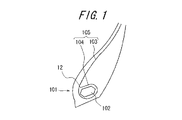
従来の空気入りタイヤにおいては、図1に示すように、図示しないトレッド部からサイドウォール部を経てビード部101までトロイド状に延びる少なくとも一枚のカーカス105を、ビード部101に埋設したビードコア102に沿って、タイヤ幅方向内側から外側へ折り返して係止することが一般的である。このようなビード部構造の下では、リム組みしたタイヤの負荷転動時に、リムフランジよりタイヤ径方向外側のビード部101が、タイヤ幅方向外側へ繰返し倒れ込み変形することに起因して、倒れ込み変形するカーカス部分及び折返し端部に応力が集中してゴムとカーカス105の間にクラックが発生し、倒れ込み変形するカーカス部分及び折返し端部がゴムとセパレーションし易くなる。
In a conventional pneumatic tire, as shown in FIG. 1, at least one
そこで、このような折返し端部のゴムとのセパレーションを防止すべく、例えば特開2001−191758号公報では、タイヤ負荷転動時に倒れ込み変形し、応力が集中し易いビード部領域に剛性を高める補強層を設けることにより、ビード部の倒れ込みを抑制して、カーカスとゴムとのセパレーションの発生を防止することが提案されている。 Therefore, in order to prevent such separation from the folded end rubber, for example, in Japanese Patent Application Laid-Open No. 2001-191758, a reinforcement that increases the rigidity in the bead portion region where the tire falls and deforms when the tire is loaded and the stress is easily concentrated. It has been proposed to prevent the occurrence of separation between the carcass and the rubber by providing a layer to suppress the falling of the bead portion.
しかし、特開2001−191758号公報に記載のタイヤにおいては、ビード部の倒れ込み変形を抑制して、ビード部におけるカーカスとゴムとのセパレーションは有効に防止してはいるが、今回、ビード部の耐久性を更に向上させたものを出願人は発明した。 However, in the tire described in Japanese Patent Application Laid-Open No. 2001-191758, the fall of the bead portion is suppressed and the separation of the carcass and the rubber in the bead portion is effectively prevented. The inventor has invented a further improved durability.
この発明は、ビード部構造の適正化を図ることにより、カーカスを構成するコードの強力の低下を防止して、ビード部の耐久性を向上させた空気入りタイヤを提供することを目的とする。 An object of the present invention is to provide a pneumatic tire in which durability of a bead portion is improved by reducing the strength of a cord constituting the carcass by optimizing the bead portion structure.
上記の目的を達成するため、この発明は、ビードコアを埋設した一対のビード部、ビード部からタイヤ径方向外側に延びる一対のサイドウォール部、及び両サイドウォール部間にまたがって延びるトレッド部の各部にわたってトロイド状に延びる本体部と、この本体部から延び、ビードコアの周りにタイヤ幅方向内側から外側に向かって折り返された折返し部からなり、ゴム被覆してなる少なくとも一枚のプライで構成されるカーカスを具える空気入りタイヤにおいて、実質的にタイヤ周方向に沿って延びるコードをゴム被覆してなる少なくとも一層の周方向補強層を、そのタイヤ径方向内側の端部をカーカスの内面に沿わせ、かつそのタイヤ径方向外側の端部をカーカスから離間させて、ビード部内に埋設してなることを特徴とする空気入りタイヤである。かかる構成により、周方向補強層によってビード部における倒れ込み変形が抑制されることから、カーカスとゴムとのセパレーションが防止することができる。また、周方向補強層のタイヤ径方向外側の端部がカーカスから離間して配置されていることから、タイヤ負荷転動時に、周方向補強層のタイヤ径方向外側の端部及びその近傍のカーカス部分に応力が集中せずに、応力が分散されるので、かかるカーカス部分のコードの強力の低下を充分に抑制し、カーカスの破壊を有効に防止することが可能となる。ここで「実質的にタイヤ周方向」とは、一本のコードを螺旋状に連続巻回して周方向補強層を形成する場合等、生産上不可避的に発生する微小な傾きも含むことを意味するものである。 In order to achieve the above object, the present invention includes a pair of bead portions in which a bead core is embedded, a pair of sidewall portions extending outward in the tire radial direction from the bead portion, and a tread portion extending between both sidewall portions. A body portion extending in a toroid shape, and a folded portion that extends from the body portion and is folded around the bead core from the inner side to the outer side in the tire width direction, and is composed of at least one ply formed by rubber coating In a pneumatic tire having a carcass, at least one circumferential reinforcing layer formed by rubber-covering a cord extending substantially along the tire circumferential direction is disposed so that an inner end in the tire radial direction is along the inner surface of the carcass. And an end portion of the outer side in the tire radial direction is separated from the carcass and embedded in the bead portion. A tire. With this configuration, the circumferential reinforcement layer suppresses the collapse deformation at the bead portion, and therefore separation between the carcass and the rubber can be prevented. Further, since the end portion on the outer side in the tire radial direction of the circumferential reinforcing layer is disposed away from the carcass, the end portion on the outer side in the tire radial direction of the circumferential reinforcing layer and the carcass in the vicinity thereof at the time of tire load rolling. Since the stress is dispersed without concentrating the stress on the portion, it is possible to sufficiently suppress the decrease in the strength of the cord of the carcass portion and effectively prevent the carcass from being broken. Here, “substantially tire circumferential direction” means including a slight inclination that is unavoidable in production, such as when a circumferential reinforcing layer is formed by continuously winding a single cord in a spiral shape. To do.
また、周方向補強層はタイヤ径方向内側の端部からタイヤ径方向外側に向かい所定の距離に亘りカーカスの内面に沿い、そこからカーカスと離間を開始し、周方向補強層のタイヤ径方向外側の端部に向かってカーカスとの離間距離を漸増させることが好ましい。ここで「離間距離」とは、タイヤ幅方向断面にて、離間した状態の周方向補強層の厚み中心位置とカーカスの厚み中心位置とをタイヤ幅方向に沿って測定した距離から離間していない状態(周方向補強層がカーカスに沿っている状態)の周方向補強層の厚み中心位置とカーカスの厚み中心位置とをタイヤ幅方向に沿って測定した距離を引いた値を言うものとする。 Further, the circumferential reinforcing layer extends along the inner surface of the carcass for a predetermined distance from the inner end in the tire radial direction toward the outer side in the tire radial direction, and starts to be separated from the carcass from there. It is preferable that the separation distance from the carcass is gradually increased toward the end portion. Here, the “separation distance” is not separated from the distance measured in the tire width direction between the thickness center position of the circumferential reinforcing layer and the thickness center position of the carcass in the tire width direction cross section. The value obtained by subtracting the distance measured along the tire width direction between the thickness center position of the circumferential reinforcement layer and the thickness center position of the carcass in a state (a state where the circumferential reinforcement layer is along the carcass).
更に、周方向補強層のタイヤ径方向外側の端部は、タイヤ径方向で見て、ビードコアの最外端よりも外側にあることが好ましい。ここで「ビードコアの最外端」とは、ビードコアのタイヤ径方向における最も外側の位置を言うものとする。 Furthermore, it is preferable that the end portion on the outer side in the tire radial direction of the circumferential reinforcing layer is outside the outermost end of the bead core as viewed in the tire radial direction. Here, the “outermost end of the bead core” refers to the outermost position of the bead core in the tire radial direction.
更にまた、周方向補強層は、タイヤ径方向で見て、ビードコアの最外端よりも外側でカーカスから離間を開始することが好ましい。 Furthermore, it is preferable that the circumferential reinforcing layer starts to be separated from the carcass outside the outermost end of the bead core when viewed in the tire radial direction.
加えて、周方向補強層のタイヤ径方向外側の端部とカーカスの離間距離が、0.5〜7.0mmの範囲内にあることが好ましく、より好ましくは0.7〜5.0mmの範囲内にある。 In addition, the separation distance between the end portion of the circumferential reinforcing layer in the tire radial direction and the carcass is preferably in the range of 0.5 to 7.0 mm, more preferably in the range of 0.7 to 5.0 mm. Is in.
加えてまた、周方向補強層とカーカスとが離間している領域に、カーカスを構成するコードの被覆ゴムよりも100%モジュラスの低いゴムで構成される軟質ゴム層を配設していることが好ましい。 In addition, a soft rubber layer made of rubber having a modulus 100% lower than that of the covering rubber of the cord constituting the carcass is disposed in a region where the circumferential reinforcing layer and the carcass are separated from each other. preferable.
また、軟質ゴム層のタイヤ径方向外側の端部は、周方向補強層のタイヤ径方向外側の端部よりもタイヤ径方向外側にあることが好ましい。 Moreover, it is preferable that the edge part of the tire radial direction outer side of a soft rubber layer exists in a tire radial direction outer side rather than the edge part of the tire radial direction outer side of a circumferential direction reinforcement layer.
更に、軟質ゴム層を構成する軟質ゴムの、カーカスを構成するコードの被覆ゴムに対する100%モジュラスの比が0.4〜0.9の範囲内にあることが好ましく、より好ましくは0.5〜0.7の範囲内にある。 Further, the ratio of the 100% modulus of the soft rubber constituting the soft rubber layer to the covering rubber of the cord constituting the carcass is preferably in the range of 0.4 to 0.9, more preferably 0.5 to It is in the range of 0.7.
更にまた、軟質ゴム層を構成する軟質ゴムの100%モジュラスが1.5〜6.5MPaの範囲内にあることが好ましく、より好ましくは2.5〜5.0MPaの範囲内にある。 Furthermore, the 100% modulus of the soft rubber constituting the soft rubber layer is preferably in the range of 1.5 to 6.5 MPa, more preferably in the range of 2.5 to 5.0 MPa.
加えて、カーカスの折返し部の全体をビードコアに沿わせて折り返すことが好ましい。このとき、カーカスの折返し部を塑性的に折り返すことが好ましい。 In addition, it is preferable that the entire folded portion of the carcass is folded along the bead core. At this time, it is preferable to plastically fold the folded portion of the carcass.
加えてまた、周方向補強層のコードの打ち込み密度が、周方向補強層のタイヤ径方向外側端部分にて、その他の部分に比べ小さくなっていることが好ましい。 In addition, it is preferable that the cord driving density of the circumferential reinforcing layer is smaller at the outer end portion in the tire radial direction of the circumferential reinforcing layer than at other portions.
また、周方向補強層のコードの打ち込み密度が、周方向補強層のタイヤ径方向外側端から、ビードコアのタイヤ幅方向最内端のタイヤ幅方向内側位置に向かって徐々に大きくなることが好ましい。ここで「ビードコアのタイヤ幅方向最内端」とは、ビードコアのタイヤ幅方向における最も内側の位置を言うものとする。 Moreover, it is preferable that the cord driving density of the circumferential reinforcing layer gradually increases from the outer end in the tire radial direction of the circumferential reinforcing layer toward the inner side in the tire width direction of the innermost end in the tire width direction of the bead core. Here, “the innermost end of the bead core in the tire width direction” refers to the innermost position of the bead core in the tire width direction.
更に、周方向補強層は、タイヤ幅方向に見て、少なくともビードコアが存在する区間にて配されていることが好ましい。このとき、周方向補強層のタイヤ径方向内側にて、周方向補強層に隣接して、ビードコアのタイヤ径方向内側を通り、タイヤ幅方向外側からタイヤ径方向外側にかけて、タイヤ周方向に対し傾斜して延びるコードをゴム被覆してなる傾斜補強層を配設していることが好ましい。ここで「周方向補強層に隣接」とは、タイヤ幅方向断面にて、傾斜補強層と周方向補強層とがオーバーラップすることなく、傾斜補強層のタイヤ径方向外側の端部と周方向補強層のタイヤ径方向内側の端部とをつき合わせて、又は離間させて、周方向補強層から延在するように延びていることをいうものとし、「タイヤ周方向に対し傾斜」とは、タイヤ周方向に対しタイヤ径方向に傾斜していることをいうものとする。 Furthermore, it is preferable that the circumferential reinforcing layer is disposed at least in a section where the bead core exists when viewed in the tire width direction. At this time, on the inner side in the tire radial direction of the circumferential direction reinforcing layer, adjacent to the circumferential direction reinforcing layer, passing through the inner side in the tire radial direction of the bead core, and inclined from the outer side in the tire width direction to the outer side in the tire radial direction with respect to the tire circumferential direction It is preferable that an inclined reinforcing layer formed by covering the extended cord with rubber is disposed. Here, “adjacent to the circumferential reinforcing layer” means that the inclined reinforcing layer and the circumferential reinforcing layer do not overlap with each other in the tire width direction cross section, and the end of the inclined reinforcing layer on the outer side in the tire radial direction and the circumferential direction. It means that it extends so as to extend from the circumferential reinforcing layer with the end of the reinforcing layer in the tire radial direction attached or separated from each other, and “inclination with respect to the tire circumferential direction” It shall mean that it is inclined in the tire radial direction with respect to the tire circumferential direction.
この発明によれば、ビード部構造の適正化を図ることにより、カーカスを構成するコードの疲労による強力の低下を防止して、ビード部の耐久性を向上させた空気入りタイヤを提供することが可能となる。 According to the present invention, by optimizing the bead portion structure, it is possible to provide a pneumatic tire that prevents a decrease in strength due to fatigue of the cords constituting the carcass and improves the durability of the bead portion. It becomes possible.
1 ビード部
2 ビードコア
3 本体部
4 折返し部
5 カーカス
6 周方向補強層
7 周方向補強層のタイヤ径方向内側の端部
8 周方向補強層のタイヤ径方向外側の端部
9 周方向補強層の厚み中心位置
10 カーカスの厚み中心位置
11 軟質ゴム層
12 折返し端部
13 傾斜補強層
X ビードコアが存在する区間DESCRIPTION OF
以下、図面を参照しつつこの発明の実施の形態を説明する。図2はこの発明に従う代表的な空気入りタイヤ(以下「タイヤ」という。)のビード部のタイヤ幅方向断面図である。 Hereinafter, embodiments of the present invention will be described with reference to the drawings. FIG. 2 is a tire width direction sectional view of a bead portion of a typical pneumatic tire (hereinafter referred to as “tire”) according to the present invention.
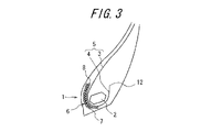
図2に示すタイヤのビード部1は、ビードコア2を埋設した一対のビード部1(図には一方のビード部1のみを示す)と、ビード部1からタイヤ径方向外側に延びる一対のサイドウォール部、及び両サイドウォール間にまたがって延びるトレッド部の各部にわたってトロイド状に延びる本体部3と、この本体部3から延び、ビードコア2の周りにタイヤ幅方向内側から外側に向かって折り返された折返し部4とからなり、ゴム被覆してなるプライで構成されるカーカス5を具えている。また、実質的にタイヤ周方向に沿って延びるコードをゴム被覆してなる一層の周方向補強層6のタイヤ径方向内側の端部7をカーカス5の内面に沿わせ、かつそのタイヤ径方向外側の端部8をカーカス5から離間させて、ビード部1内に埋設している。このとき、剛性の高い周方向補強層6がタイヤ負荷転動時に倒れ込み変形を起こし易い部分に配設されることから、倒れ込み変形が抑制され、カーカス5とゴムとのセパレーションが防止されている。また、補強層8のコードとカーカス5のコードとが直交する方向に配設されているので、カーカス5に引張力が働く際に、補強層6のコードが引っ掛かりとなって係止力が向上し、引き抜け防止効果を向上させている。なお、周方向補強層6がカーカス5に完全に沿っていると、部分的に離間している場合に比べ、カーカス5を挟み込むビードコア2と周方向補強層6との離間距離が全体に小さくなり、強く挟み込まれるカーカス部分が大きくなるので、カーカス5の引き抜けの発生が強く抑制されるが、タイヤ負荷転動時に繰返し強く引っ張られるカーカス部分も大きくなるので、疲労が蓄積しコードの強力が低下するカーカス部分も大きくなる。図2に示すこの発明のタイヤでは、周方向補強層6のタイヤ径方向外側の端部8がカーカス5から離間して配設されていることから、カーカス5の引き抜けを抑制しつつも、周方向補強層6をカーカス5に完全に沿わせて配置する場合に比べ、ビードコア2と周方向補強層6とで挟み込まれるカーカス部分が減少して、その減少した分だけ、タイヤ負荷転動時に疲労が蓄積しコードの強力が低下する方向のカーカス部分が減少するので、結果としてビード部1の耐久性を有効に向上させることが可能となる。また、タイヤ負荷転動の際に、周方向補強層6のタイヤ径方向外側の端部8及びその近傍のカーカス部分に応力が集中せずに分散されることとなり、カーカス5が疲労することなく、そのコードの強力の低下を防止し、ビード部1の耐久性を有効に向上させることが可能となる。なお、図3に示すように、倒れ込み変形を更に強く抑制するために周方向補強層6を2層と増やすことも可能である。
The
更に、周方向補強層6はタイヤ径方向内側の端部7からタイヤ径方向外側に向かい所定の距離に亘りカーカス5の内面に沿い、そこからカーカス5と離間を開始し、周方向補強層6のタイヤ径方向外側の端部8に向かってカーカス5との離間距離を漸増させることが好ましい。なぜなら、このように離間距離が漸増する場合には、周方向補強層6のタイヤ径方向外側の端部8への応力の集中に起因する周方向補強層6のタイヤ径方向外側の端部近傍のカーカス5のコードへの応力の集中が回避され、周方向補強層6のタイヤ径方向外側の端部8からカーカスへの応力が段階的に分散されることから、その他のビード部領域に局所的に応力が集中することなく、カーカス5のコードの疲労による強力の低下が抑制される可能性があるからである。なお、図12に示すように、離間距離とは、タイヤ幅方向断面にて、離間した状態の周方向補強層6の厚み中心位置9とカーカス5の厚み中心位置10とをタイヤ幅方向に沿って測定した距離d1から、離間していない状態の周方向補強層6の厚み中心位置9とカーカス5の厚み中心位置10とをタイヤ幅方向に沿って測定した距離d2を引いた値(d1−d2)のことを言う。
Further, the circumferential reinforcing
更にまた、周方向補強層6のタイヤ径方向外側の端部8は、タイヤ径方向で見て、ビードコア2の最外端よりも外側にあることが好ましい。なぜなら、周方向補強層6のタイヤ径方向外側の端部は、タイヤ径方向で見て、ビードコア2の最外端より応力が外側にあることにより、タイヤ負荷転動時に、ビードコア2のタイヤ径方向の最外端に集中することなく、カーカス5の倒れ込み変形がビードコア2のタイヤ径方向の最外端近傍のカーカス部分で起こることを抑制することができることから、ビードコア2のタイヤ径方向の最外端近傍のカーカス部分のコードの疲労による強力の低下を防止して、ビード部1の耐久性を向上させることができる可能性があるからである。
Furthermore, it is preferable that the
加えて、周方向補強層6は、タイヤ径方向に見て、ビードコア2の最外端よりも外側でカーカス5から離間を開始することが好ましい。なぜなら、周方向補強層6がビードコア2のタイヤ径方向最外端よりも内側でカーカス5から離間を開始する場合には、タイヤ負荷転動時に倒れ込み変形しやすいビードコア2のタイヤ径方向最外端近傍のカーカス部分及びそのタイヤ径方向外側近傍のカーカス部分の剛性を充分に向上することができずに、カーカス5の倒れ込み変形を有効に防止することができなくなり、周方向補強層6を配設することによりカーカス5の剛性を高めてその倒れ込み変形を防止するという本来の役割を果たさない可能性があるからである。また、ビードコア2の最外端よりも外側でカーカス5から離間を開始することにより、ビードコア2のタイヤ径方向最外端よりもタイヤ径方向内側において、ビードコア2と周方向補強層6でカーカス5を挟み込む領域が増加し、挟み込みの効果が向上するので、カーカス5の引き抜けが発生しにくくなる可能性があるからである。
In addition, it is preferable that the circumferential reinforcing
加えてまた、周方向補強層6のタイヤ径方向外側の端部8とカーカス5の離間距離が、0.5〜7.0mmの範囲内にあることが好ましく、より好ましくは0.7〜5.0mmの範囲内にある。なぜなら、一方において、周方向補強層6のダイヤ径方向外側の端部とカーカス5の離間距離が0.5mm未満の場合には、周方向補強層6のタイヤ径方向外側の端部8とその近傍のカーカス部分の剛性が過剰に高まり、過剰な剛性段差が生じるので、剛性段差の大きな部分で倒れ込み変形し易くなり、周方向補強層6のタイヤ径方向外側の端部8及びその近傍のカーカス部分に応力が局所的に集中することとなり、カーカス5のコードの局所的な疲労を招き、ビード部1の耐久性を低下させる可能性があり、また、後述する軟質ゴム層11を配設する領域を確保することが困難となる可能性があるからである。また、他方において、周方向補強層6のダイヤ径方向外側の端部とカーカス5の離間距離が7.0mmを超える場合には、周方向補強層6とカーカス5が離間距離が長くなり過ぎ、カーカス5の倒れ込み変形が起こり易い領域の剛性を充分に高めることができなくなることから、タイヤ負荷転動時に倒れ込み変形を充分に抑制することができずに、倒れ込み変形に起因するカーカス5の疲労を招き、ビード部1の耐久性の低下を引き起こす可能性があるからである。
In addition, the separation distance between the
また、図4又は図5に示すように、周方向補強層6とカーカス5とが離間している領域に、カーカス5を構成するコードの被覆ゴムよりも100%モジュラスの低いゴムで構成される軟質ゴム層11を配設することが好ましい。なぜなら、本来ならば周方向補強層6をカーカス5から大きく離間させることで応力の局所的な集中を分散する効果が得られるところ、周方向補強層6とカーカス5とが離間している領域に、カーカス5を構成するコードの被覆ゴムよりも100%モジュラスの低いゴムで構成される軟質ゴム層11を配設することにより、軟質ゴム層が10周方向補強層6とカーカス5とが離間している領域の柔軟性を高め、周方向補強層6とカーカス5を大きく離間させずに、周方向補強層6とカーカス5を大きく離間させた場合と同様に応力の局所的な集中を分散する効果が得られることから、周方向補強層6とカーカス5を離間させることによる製造工程上の困難を克服し、また、周方向補強層6とカーカス5を大きく離間させることに伴うビード部1の形状の制約や重量の増加がなされることなく、従来通りのビード部構造の柔軟性を確保することができる可能性があるからである。
Further, as shown in FIG. 4 or FIG. 5, the region in which the circumferential reinforcing
更にまた、図4又は図5に示すように、軟質ゴム層11のタイヤ径方向外側の端部は、周方向補強層6のタイヤ径方向外側の端部8よりもタイヤ径方向外側にあることが好ましい。なぜなら、軟質ゴム層11のタイヤ径方向外側の端部が、周方向補強層6のタイヤ径方向外側の端部8よりもタイヤ径方向外側にあることにより、軟質ゴム層11のタイヤ径方向外側の端部が周方向補強層6のタイヤ径方向外側の端部8よりもタイヤ径方向内側にある場合と比較して、応力が過剰に集中しやすい領域に充分に軟質ゴム層11が配設されることとなり、周方向補強層6のタイヤ径方向外側の端部8及びその近傍のカーカス部分に応力が局所的に集中しないように、応力を確実に分散させることができる可能性があるからである。
Furthermore, as shown in FIG. 4 or FIG. 5, the end portion of the
更に、軟質ゴム層11を構成する軟質ゴムの、カーカス5を構成するコードの被覆ゴムに対する100%モジュラスの比が0.4〜0.9の範囲内にあることが好ましく、より好ましくは0.5〜0.7の範囲内である。なぜなら、一方において、軟質ゴム層11を構成する軟質ゴムの、カーカス5を構成するコードの被覆ゴムに対する100%モジュラスの比が0.4よりも大きい場合には、軟質ゴム層11とカーカス5を構成するコードの被覆ゴムの剛性の差が大きくなりすぎ、タイヤ負荷転動時に、軟質ゴム層11とカーカス5を構成するコードの被覆ゴムの境界領域に応力が過剰に集中することとなり、その境界領域に疲労が蓄積し、軟質ゴムとカーカス5を構成するコードの被覆ゴム間のセパレーションを招く可能性があるからである。また、他方において、かかる100%モジュラスの比が0.9よりも小さい場合には、軟質ゴム層11とカーカス5を構成するコードの被覆ゴムの100%モジュラスが実質的に略同一となり、軟質ゴム層11を配設することによる効果が有効に得られない可能性があるからである。
Further, the ratio of the 100% modulus of the soft rubber constituting the
加えて、軟質ゴム層を構成する軟質ゴムの100%モジュラスが1.5〜6.5MPaの範囲内にあることが好ましく、より好ましくは2.5〜5.0MPaの範囲内にある。なぜなら、軟質ゴムの100%モジュラスが5.0MPaを超える場合には、軟質ゴムの剛性が必要以上に高いために、周方向補強層6とその近傍にあるカーカス部分への応力の集中を充分に分散することなく、かかるカーカス部分が疲労する可能性があり、軟質ゴムの100%モジュラスが1.5MPa未満の場合には、タイヤ負荷転同時における周方向補強層6のタイヤ径方向外側の端部8及びその近傍のカーカス部分への応力の局所的な集中を充分に分散することができるが、軟質ゴム層11近傍の剛性が低くなり過ぎることから、周方向補強層6を配設することによる効果が低下することとなり、タイヤ負荷転同時のビード部1の倒れ込み変形を充分に防止することができなくなる可能性があるからである。
In addition, the 100% modulus of the soft rubber constituting the soft rubber layer is preferably in the range of 1.5 to 6.5 MPa, more preferably in the range of 2.5 to 5.0 MPa. This is because when the 100% modulus of the soft rubber exceeds 5.0 MPa, the rigidity of the soft rubber is higher than necessary, so that the stress is sufficiently concentrated on the circumferential reinforcing
加えてまた、図2、図4及び図6〜8に示すように、カーカス5の折返し部4の全体をビードコア2に沿わせて折り返すことが好ましい。なぜなら、折返し部4全体をビードコア2に沿わせて折り返すことにより、リム組みしたタイヤの負荷転動時に、ビード部1がタイヤ幅方向外側へ倒れ込み変形しても、折返し端部12に応力が集中することなく、ゴムと折返し端部12の間がクラックする可能性が低減するので、カーカス5がゴムとセパレーションしにくくなるとともに、カーカス5をビードコア2に巻き付けることにより引張応力に抗する係止力が向上することから、カーカス5のビード部1からの引き抜けが更に発生しにくくなるからである。また、このとき、カーカス5の折返し部4をビードコア2に沿って塑性的に折り返すことが好ましい。なぜなら、塑性的に折り返すことにより、弾性的に折り返す場合に比べ、カーカス5の折返し部4がビードコア2とより合致した形状となり、カーカス5の折返し部4とビードコア2との離間距離が全体に小さくなるので、カーカス5の折返し部4がビードコア2に強く係止されることとなり、カーカス5のタイヤ径方向外側への引張力に抵抗する係止力が更に向上し、カーカス5のビード部1からの引き抜けがより一層抑制されるからである。
In addition, as shown in FIGS. 2, 4, and 6 to 8, it is preferable that the entire folded
また、図9に示すように、周方向補強層6のコードの打ち込み密度が、周方向補強層6のタイヤ径方向外側部分にて、その他の部分に比べ小さくなっていることが好ましい。タイヤ内の圧力によりビード部1をタイヤ幅方向内側から外側に押圧する力が働くことから、少なくともビードコア2のタイヤ幅方向内側にあるカーカス部分を、打ち込み密度の大きなコードを有する周方向補強層部分とビードコア2とで挟み込めば、カーカス5が強く挟み込まれ、カーカス5の引き抜けを防止することができる。一方、周方向補強層6のタイヤ径方向外側端側にあるコード程、ビードコア2から離間しており、かかる離間した位置に周方向補強層6を配設しても、挟み込みによる効果が小さく、周方向補強層6のタイヤ径方向外側部分にあるコードの打ち込み密度を小さくしても、カーカス5の挟み込みに大きく影響しない。そのことから、周方向補強層6のタイヤ径方向外側部分のコードの打ち込み密度を小さくして、周方向補強層6のタイヤ径方向外側部分におけるカーカス5への応力集中を抑制し、ビード部1の耐久性を向上させることができる。なお、このとき、上記した構成の範囲内であれば、周方向補強層6のコードの打ち込み密度を少なくとも一部を不均一としてもよい。
Moreover, as shown in FIG. 9, it is preferable that the cord driving density of the circumferential reinforcing
更に、図10に示すように、周方向補強層6のコードの打ち込み密度が、周方向補強層6のタイヤ径方向外側端から、ビードコア2のタイヤ幅方向最内端のタイヤ幅方向内側位置に向かって所定の大きさ迄大きくなることが好ましい。なぜなら、ビードコア2のタイヤ幅方向最内端のタイヤ幅方向内側位置に近いほどビードコア2と周方向補強層6との離間距離が小さくなり、その間に挟みこまれるカーカス5が強く挟み込まれるので、周方向補強層6のタイヤ径方向外側端から、ビードコア2のタイヤ幅方向最内端のタイヤ幅方向内側位置に向かって周方向補強層6のコードの打ち込み密度を所定の大きさ迄大きくすると、打ち込み密度の大きなコードを有する周方向補強層部分とビードコア2とによりカーカス5を強く挟み込むことができ、カーカス5のビード部1からの引き抜けを有効に抑制することが可能となるからである。また、周方向補強層6からタイヤ径方向外側に離間した位置にあるコード程打ち込み密度が小さくなっているので、カーカス5への応力集中を抑制し、ビード部1の耐久性を向上させることができるからである。
Furthermore, as shown in FIG. 10, the cord driving density of the circumferential reinforcing
更にまた、図11に示すように、周方向補強層6は、タイヤ幅方向に見て、ビードコア2が存在する区間Xにて配されていることが好ましい。なぜなら、タイヤ内の圧力によりビード部1をタイヤ幅方向内側から外側に押圧する力が働くことから、少なくともビードコア2のタイヤ幅方向内側にあるカーカス部分を、周方向補強層6とビードコア2とで挟み込めば、カーカス5が強く挟み込まれ、カーカス5の引き抜けを防止することができるからである。また、このとき、周方向補強層6のタイヤ径方向内側にて、周方向補強層6に隣接して、タイヤ周方向に対し傾斜して延びるコードをゴム被覆してなる傾斜補強層13を配設していることが好ましい。なぜなら、傾斜補強層13を構成するコードがタイヤ周方向に対し傾斜する方向に延びていることから、かかるコードがビード部1のタイヤ周方向への変形に抗する剛性を高め、タイヤ負荷転動時の路面との摩擦により、トレッド部の路面接地開始位置近傍から接地終了位置近傍までの間にあるビード部1がタイヤ周方向へと変形することを抑制して、リムずれを有効に防止することができるからである。
Furthermore, as shown in FIG. 11, it is preferable that the circumferential reinforcing
なお、ビードコア2は、楕円形状やその他の多角形状など種々の形状に適宜変更しても良い。また、上述したところはこの発明の実施形態の一部を示したに過ぎず、この発明の趣旨を逸脱しない限り、これらの構成を交互に組み合わせたり、種々の変更を加えたりすることができる。
The
次に、図2〜7に示すビード部を有するこの発明のタイヤ(実施例)、従来技術のビード部を有するタイヤ(従来例)を夫々試作し、性能評価を行ったので、以下に説明する。 Next, tires of the present invention having the bead portions shown in FIGS. 2 to 7 (Examples) and tires having the bead portions of the prior art (conventional examples) were respectively prototyped and performance evaluations were performed, which will be described below. .
実施例1〜5のタイヤは夫々図2〜6に示す構造のビード部を有するバストラック用のタイヤであり、実施例6のタイヤは図7に示す構造のビード部を有する建設車両用のタイヤである。図示していないが、従来例1、2、5及び6のタイヤは、周方向補強層のタイヤ径方向外側の端部とカーカスの離間距離が0(mm)となっている点を除いて、基本的には夫々が実施例1、2、5及び6のタイヤと同様の構成を有している。また、同様に図示していないが、従来例3及び4のタイヤは、軟質ゴム層を配設されていない点及び周方向補強層のタイヤ径方向外側の端部とカーカスの離間距離が0(mm)となっている点を除いて、基本的には夫々が実施例3及び4のタイヤと同様の構成を有している。これら試作されたタイヤは、周方向補強層がスチールコードにより構成されており、表1に示す諸元を有する。 The tires of Examples 1 to 5 are bus truck tires having bead portions having the structure shown in FIGS. 2 to 6, respectively. The tires of Example 6 are tires for construction vehicles having bead portions having the structure shown in FIG. It is. Although not shown, the tires of the conventional examples 1, 2, 5 and 6 except that the circumferential distance between the end portion of the circumferential reinforcing layer in the tire radial direction and the carcass is 0 (mm), Basically, each has the same configuration as the tires of Examples 1, 2, 5 and 6. Similarly, although not shown in the drawings, the tires of the conventional examples 3 and 4 have no soft rubber layer and the circumferential distance between the end of the circumferential reinforcing layer in the tire radial direction and the carcass is 0 ( Each of the tires basically has the same configuration as that of the tires of Examples 3 and 4 except for the point of (mm). These prototype tires have the specifications shown in Table 1 in which the circumferential reinforcing layer is made of a steel cord.

これら各供試タイヤを表1に示す所定のサイズのリムに取り付けてタイヤ車輪とし、このタイヤ車輪をテスト車両に装着して、表2に示すタイヤ内圧(相対圧で表示されている)、タイヤ負荷荷重等の各種条件を適用し、規定の距離を走行後にタイヤからプライを取り出し、それを構成するコードの引張破断強力を測定してビード部の耐久性の評価を行った。 Each of these test tires is attached to a rim having a predetermined size shown in Table 1 to form a tire wheel. The tire wheel is mounted on a test vehicle, and the tire internal pressure (indicated by relative pressure) shown in Table 2 is set. Various conditions such as applied load were applied, the ply was taken out of the tire after traveling a specified distance, and the tensile strength at break of the cord constituting the ply was measured to evaluate the durability of the bead portion.
このテストの評価結果を表2に示す。なお、表2の評価結果は、夫々に対応する従来例のタイヤのカーカスを構成するコードの引張破断強力を100としたときの指数比で示してあり、数値が大きいほどその性能が優れていることを示している。 The evaluation results of this test are shown in Table 2. The evaluation results in Table 2 are shown as index ratios when the tensile rupture strength of the cords constituting the carcass of the conventional tires corresponding to each is 100, and the larger the value, the better the performance. It is shown that.
表2の結果が示すように、実施例のタイヤは、従来例のタイヤに比べ、引張破断強力の評価が20%〜35%向上していた。したがって、かかる構成により、カーカスを構成するコードの疲労による強力の低下を防止して、ビード部の耐久性を向上させていることがわかる。 As the results of Table 2 show, the tires of the examples had an improvement in tensile strength at break of 20% to 35% compared to the tires of the conventional examples. Therefore, it can be seen that such a configuration prevents a decrease in strength due to fatigue of the cords constituting the carcass and improves the durability of the bead portion.
以上の結果から明らかになったように、ビード部構造の適正化を図ることにより、カーカスを構成するコードの疲労による強力の低下を防止して、ビード部の耐久性を向上させることができる空気入りタイヤを提供することが可能となった。 As can be seen from the above results, by optimizing the structure of the bead part, air that can prevent the deterioration of the strength due to fatigue of the cord constituting the carcass and improve the durability of the bead part. It has become possible to provide tires containing tires.
Claims (15)
実質的にタイヤ周方向に沿って延びるコードをゴム被覆してなる少なくとも一層の周方向補強層を、そのタイヤ径方向内側の端部を前記カーカスの内面に沿わせ、かつそのタイヤ径方向外側の端部をカーカスから離間させて、前記ビード部内に埋設してなることを特徴とする空気入りタイヤ。A main body portion extending in a toroid shape across each of a pair of bead portions in which a bead core is embedded, a pair of sidewall portions extending outward from the bead portion in the tire radial direction, and a tread portion extending between both side wall portions, and the main body portion In a pneumatic tire comprising a carcass composed of at least one ply formed of a folded portion extending from the inner side in the tire width direction toward the outer side around the bead core.
At least one circumferential reinforcing layer formed by rubber-covering a cord extending substantially along the tire circumferential direction has an end portion on the inner side in the tire radial direction along the inner surface of the carcass and on the outer side in the tire radial direction. A pneumatic tire characterized in that an end portion is separated from a carcass and embedded in the bead portion.
Priority Applications (1)
| Application Number | Priority Date | Filing Date | Title |
|---|---|---|---|
| JP2008539897A JP5048677B2 (en) | 2006-10-20 | 2007-10-22 | Pneumatic tire |
Applications Claiming Priority (4)
| Application Number | Priority Date | Filing Date | Title |
|---|---|---|---|
| JP2006286067 | 2006-10-20 | ||
| JP2006286067 | 2006-10-20 | ||
| PCT/JP2007/070579 WO2008047939A1 (en) | 2006-10-20 | 2007-10-22 | Pneumatic tire |
| JP2008539897A JP5048677B2 (en) | 2006-10-20 | 2007-10-22 | Pneumatic tire |
Publications (2)
| Publication Number | Publication Date |
|---|---|
| JPWO2008047939A1 JPWO2008047939A1 (en) | 2010-02-25 |
| JP5048677B2 true JP5048677B2 (en) | 2012-10-17 |
Family
ID=39314147
Family Applications (1)
| Application Number | Title | Priority Date | Filing Date |
|---|---|---|---|
| JP2008539897A Expired - Fee Related JP5048677B2 (en) | 2006-10-20 | 2007-10-22 | Pneumatic tire |
Country Status (8)
| Country | Link |
|---|---|
| US (1) | US20100314017A1 (en) |
| EP (1) | EP2077195B1 (en) |
| JP (1) | JP5048677B2 (en) |
| KR (1) | KR101060046B1 (en) |
| CN (1) | CN101541565B (en) |
| AT (1) | ATE534537T1 (en) |
| ES (1) | ES2375760T3 (en) |
| WO (1) | WO2008047939A1 (en) |
Families Citing this family (2)
| Publication number | Priority date | Publication date | Assignee | Title |
|---|---|---|---|---|
| JP2010013043A (en) * | 2008-07-07 | 2010-01-21 | Bridgestone Corp | Tire |
| CN114312156A (en) * | 2022-01-27 | 2022-04-12 | 青岛双星轮胎工业有限公司 | Composite support rubber and self-supporting tire |
Family Cites Families (8)
| Publication number | Priority date | Publication date | Assignee | Title |
|---|---|---|---|---|
| FR1407685A (en) * | 1964-05-27 | 1965-08-06 | Pneumatiques, Caoutchouc Manufacture Et Plastiques Kleber Colombes | Tire casing |
| FR2773517B1 (en) * | 1998-01-12 | 2000-02-04 | Michelin & Cie | TIRE SADDLE WITH CIRCUMFERENTIAL REINFORCEMENT ELEMENTS |
| FR2773519B1 (en) * | 1998-01-12 | 2000-02-11 | Michelin & Cie | TIRE SADDLE WITH CIRCUMFERENTIAL REINFORCEMENT ELEMENTS |
| JP4462688B2 (en) | 2000-01-13 | 2010-05-12 | 株式会社ブリヂストン | Pneumatic tire with excellent bead durability |
| US6491079B2 (en) * | 2000-01-14 | 2002-12-10 | Bridgestone Corporation | Pneumatic tire with turnup portion wrapped along outer peripheral face of bead core |
| JP3902177B2 (en) * | 2003-12-10 | 2007-04-04 | 住友ゴム工業株式会社 | Heavy duty tire |
| JP2006175955A (en) | 2004-12-21 | 2006-07-06 | Bridgestone Corp | Pneumatic tire and manufacturing method thereof |
| JP2006188147A (en) * | 2005-01-06 | 2006-07-20 | Bridgestone Corp | Pneumatic tire |
-
2007
- 2007-10-22 ES ES07830313T patent/ES2375760T3/en active Active
- 2007-10-22 EP EP07830313A patent/EP2077195B1/en not_active Not-in-force
- 2007-10-22 JP JP2008539897A patent/JP5048677B2/en not_active Expired - Fee Related
- 2007-10-22 KR KR1020097008005A patent/KR101060046B1/en active IP Right Grant
- 2007-10-22 WO PCT/JP2007/070579 patent/WO2008047939A1/en active Application Filing
- 2007-10-22 CN CN200780043367XA patent/CN101541565B/en not_active Expired - Fee Related
- 2007-10-22 US US12/445,698 patent/US20100314017A1/en not_active Abandoned
- 2007-10-22 AT AT07830313T patent/ATE534537T1/en active
Also Published As
| Publication number | Publication date |
|---|---|
| KR101060046B1 (en) | 2011-08-29 |
| ATE534537T1 (en) | 2011-12-15 |
| JPWO2008047939A1 (en) | 2010-02-25 |
| ES2375760T3 (en) | 2012-03-06 |
| WO2008047939A1 (en) | 2008-04-24 |
| KR20090069307A (en) | 2009-06-30 |
| US20100314017A1 (en) | 2010-12-16 |
| EP2077195B1 (en) | 2011-11-23 |
| CN101541565B (en) | 2011-05-25 |
| EP2077195A1 (en) | 2009-07-08 |
| CN101541565A (en) | 2009-09-23 |
| EP2077195A4 (en) | 2010-07-07 |
Similar Documents
| Publication | Publication Date | Title |
|---|---|---|
| JP5091223B2 (en) | Pneumatic radial tire | |
| JP5390392B2 (en) | Pneumatic tire | |
| JP5973772B2 (en) | Run flat tire | |
| JP2010018123A (en) | Pneumatic tire | |
| JP5205272B2 (en) | Pneumatic tire | |
| JP2002120521A (en) | Pneumatic radial tire | |
| JP2010111370A (en) | Pneumatic tire | |
| JP5048677B2 (en) | Pneumatic tire | |
| JP2008174167A (en) | Pneumatic tire | |
| JP5003026B2 (en) | Pneumatic tire | |
| JP6852092B2 (en) | Pneumatic tires for motorcycles | |
| JP2022173595A (en) | Automobile pneumatic radial tire | |
| JP4606184B2 (en) | Pneumatic tire | |
| JP2002219913A (en) | Pneumatic radial tire for heavy load | |
| JP4431075B2 (en) | Heavy duty tire | |
| WO2007094281A1 (en) | Pneumatic tire | |
| JP4338471B2 (en) | Radial tire for light truck | |
| JP5495426B2 (en) | Pneumatic radial tire and manufacturing method thereof | |
| JP2010120401A (en) | Pneumatic tire | |
| EP4296093A1 (en) | Pneumatic tire | |
| JP7329106B2 (en) | Pneumatic radial tires for passenger cars | |
| JPH0466310A (en) | Pneumatic tire | |
| JP5399700B2 (en) | Pneumatic tire | |
| JP5094102B2 (en) | Pneumatic radial tire for aircraft | |
| JP2007331435A (en) | Pneumatic tire |
Legal Events
| Date | Code | Title | Description |
|---|---|---|---|
| A621 | Written request for application examination |
Free format text: JAPANESE INTERMEDIATE CODE: A621 Effective date: 20100908 |
|
| TRDD | Decision of grant or rejection written | ||
| A01 | Written decision to grant a patent or to grant a registration (utility model) |
Free format text: JAPANESE INTERMEDIATE CODE: A01 Effective date: 20120619 |
|
| A01 | Written decision to grant a patent or to grant a registration (utility model) |
Free format text: JAPANESE INTERMEDIATE CODE: A01 |
|
| A61 | First payment of annual fees (during grant procedure) |
Free format text: JAPANESE INTERMEDIATE CODE: A61 Effective date: 20120719 |
|
| FPAY | Renewal fee payment (event date is renewal date of database) |
Free format text: PAYMENT UNTIL: 20150727 Year of fee payment: 3 |
|
| R150 | Certificate of patent or registration of utility model |
Ref document number: 5048677 Country of ref document: JP Free format text: JAPANESE INTERMEDIATE CODE: R150 Free format text: JAPANESE INTERMEDIATE CODE: R150 |
|
| R250 | Receipt of annual fees |
Free format text: JAPANESE INTERMEDIATE CODE: R250 |
|
| R250 | Receipt of annual fees |
Free format text: JAPANESE INTERMEDIATE CODE: R250 |
|
| R250 | Receipt of annual fees |
Free format text: JAPANESE INTERMEDIATE CODE: R250 |
|
| R250 | Receipt of annual fees |
Free format text: JAPANESE INTERMEDIATE CODE: R250 |
|
| R250 | Receipt of annual fees |
Free format text: JAPANESE INTERMEDIATE CODE: R250 |
|
| R250 | Receipt of annual fees |
Free format text: JAPANESE INTERMEDIATE CODE: R250 |
|
| LAPS | Cancellation because of no payment of annual fees |