JP5202959B2 - High refractive index uniform fused silica glass and method for producing the same - Google Patents
High refractive index uniform fused silica glass and method for producing the same Download PDFInfo
- Publication number
- JP5202959B2 JP5202959B2 JP2007549589A JP2007549589A JP5202959B2 JP 5202959 B2 JP5202959 B2 JP 5202959B2 JP 2007549589 A JP2007549589 A JP 2007549589A JP 2007549589 A JP2007549589 A JP 2007549589A JP 5202959 B2 JP5202959 B2 JP 5202959B2
- Authority
- JP
- Japan
- Prior art keywords
- soot
- glass
- preform
- ppm
- less
- Prior art date
- Legal status (The legal status is an assumption and is not a legal conclusion. Google has not performed a legal analysis and makes no representation as to the accuracy of the status listed.)
- Active
Links
- 238000004519 manufacturing process Methods 0.000 title claims description 22
- 239000005350 fused silica glass Substances 0.000 title description 60
- VYPSYNLAJGMNEJ-UHFFFAOYSA-N Silicium dioxide Chemical compound O=[Si]=O VYPSYNLAJGMNEJ-UHFFFAOYSA-N 0.000 claims description 172
- 239000004071 soot Substances 0.000 claims description 161
- 239000011521 glass Substances 0.000 claims description 110
- 238000000034 method Methods 0.000 claims description 85
- 239000000463 material Substances 0.000 claims description 63
- 230000003287 optical effect Effects 0.000 claims description 53
- 239000000377 silicon dioxide Substances 0.000 claims description 45
- 239000002245 particle Substances 0.000 claims description 29
- 150000001875 compounds Chemical class 0.000 claims description 25
- 238000000151 deposition Methods 0.000 claims description 23
- 239000000203 mixture Substances 0.000 claims description 18
- 230000007062 hydrolysis Effects 0.000 claims description 17
- 238000006460 hydrolysis reaction Methods 0.000 claims description 17
- 230000008569 process Effects 0.000 claims description 17
- 239000002243 precursor Substances 0.000 claims description 14
- 239000001307 helium Substances 0.000 claims description 10
- 229910052734 helium Inorganic materials 0.000 claims description 10
- SWQJXJOGLNCZEY-UHFFFAOYSA-N helium atom Chemical compound [He] SWQJXJOGLNCZEY-UHFFFAOYSA-N 0.000 claims description 10
- 206010040925 Skin striae Diseases 0.000 claims description 8
- XUIMIQQOPSSXEZ-UHFFFAOYSA-N Silicon Chemical compound [Si] XUIMIQQOPSSXEZ-UHFFFAOYSA-N 0.000 claims description 7
- 239000010703 silicon Substances 0.000 claims description 7
- 229910052710 silicon Inorganic materials 0.000 claims description 7
- XLYOFNOQVPJJNP-UHFFFAOYSA-N water Substances O XLYOFNOQVPJJNP-UHFFFAOYSA-N 0.000 claims description 4
- 229910001868 water Inorganic materials 0.000 claims description 4
- 239000000523 sample Substances 0.000 description 56
- 238000005245 sintering Methods 0.000 description 27
- 239000000460 chlorine Substances 0.000 description 22
- 229910052801 chlorine Inorganic materials 0.000 description 20
- ZAMOUSCENKQFHK-UHFFFAOYSA-N Chlorine atom Chemical compound [Cl] ZAMOUSCENKQFHK-UHFFFAOYSA-N 0.000 description 17
- 230000008859 change Effects 0.000 description 17
- 238000010521 absorption reaction Methods 0.000 description 15
- 238000007596 consolidation process Methods 0.000 description 15
- 230000008021 deposition Effects 0.000 description 14
- 238000010586 diagram Methods 0.000 description 12
- 229910052739 hydrogen Inorganic materials 0.000 description 10
- UFHFLCQGNIYNRP-UHFFFAOYSA-N Hydrogen Chemical compound [H][H] UFHFLCQGNIYNRP-UHFFFAOYSA-N 0.000 description 9
- 229910052731 fluorine Inorganic materials 0.000 description 9
- 239000001257 hydrogen Substances 0.000 description 9
- 230000007423 decrease Effects 0.000 description 8
- 230000000694 effects Effects 0.000 description 8
- HMMGMWAXVFQUOA-UHFFFAOYSA-N octamethylcyclotetrasiloxane Chemical compound C[Si]1(C)O[Si](C)(C)O[Si](C)(C)O[Si](C)(C)O1 HMMGMWAXVFQUOA-UHFFFAOYSA-N 0.000 description 8
- 239000012686 silicon precursor Substances 0.000 description 8
- 125000002887 hydroxy group Chemical group [H]O* 0.000 description 7
- 229910052760 oxygen Inorganic materials 0.000 description 7
- 238000002834 transmittance Methods 0.000 description 7
- YCKRFDGAMUMZLT-UHFFFAOYSA-N Fluorine atom Chemical compound [F] YCKRFDGAMUMZLT-UHFFFAOYSA-N 0.000 description 6
- QVGXLLKOCUKJST-UHFFFAOYSA-N atomic oxygen Chemical compound [O] QVGXLLKOCUKJST-UHFFFAOYSA-N 0.000 description 6
- 230000005540 biological transmission Effects 0.000 description 6
- 230000015556 catabolic process Effects 0.000 description 6
- 238000006731 degradation reaction Methods 0.000 description 6
- 239000011737 fluorine Substances 0.000 description 6
- 238000000265 homogenisation Methods 0.000 description 6
- 239000001301 oxygen Substances 0.000 description 6
- 238000005033 Fourier transform infrared spectroscopy Methods 0.000 description 5
- 229910004298 SiO 2 Inorganic materials 0.000 description 5
- 229910052784 alkaline earth metal Inorganic materials 0.000 description 5
- 150000001342 alkaline earth metals Chemical class 0.000 description 5
- 230000005855 radiation Effects 0.000 description 5
- 229910052723 transition metal Inorganic materials 0.000 description 5
- 238000001069 Raman spectroscopy Methods 0.000 description 4
- 229910003902 SiCl 4 Inorganic materials 0.000 description 4
- 229910052783 alkali metal Inorganic materials 0.000 description 4
- 150000001340 alkali metals Chemical class 0.000 description 4
- 238000004458 analytical method Methods 0.000 description 4
- 239000002019 doping agent Substances 0.000 description 4
- 239000005304 optical glass Substances 0.000 description 4
- 150000003624 transition metals Chemical class 0.000 description 4
- 230000008901 benefit Effects 0.000 description 3
- 230000015572 biosynthetic process Effects 0.000 description 3
- 230000007547 defect Effects 0.000 description 3
- 230000002950 deficient Effects 0.000 description 3
- 238000000280 densification Methods 0.000 description 3
- 230000006870 function Effects 0.000 description 3
- 230000006872 improvement Effects 0.000 description 3
- 238000012545 processing Methods 0.000 description 3
- 238000011160 research Methods 0.000 description 3
- 238000007740 vapor deposition Methods 0.000 description 3
- XKRFYHLGVUSROY-UHFFFAOYSA-N Argon Chemical compound [Ar] XKRFYHLGVUSROY-UHFFFAOYSA-N 0.000 description 2
- 229910002808 Si–O–Si Inorganic materials 0.000 description 2
- 230000004075 alteration Effects 0.000 description 2
- 238000006243 chemical reaction Methods 0.000 description 2
- 230000000052 comparative effect Effects 0.000 description 2
- 230000006835 compression Effects 0.000 description 2
- 238000007906 compression Methods 0.000 description 2
- 230000003247 decreasing effect Effects 0.000 description 2
- 239000007789 gas Substances 0.000 description 2
- 238000010438 heat treatment Methods 0.000 description 2
- 150000002431 hydrogen Chemical class 0.000 description 2
- 238000011065 in-situ storage Methods 0.000 description 2
- 238000005259 measurement Methods 0.000 description 2
- 229910052751 metal Inorganic materials 0.000 description 2
- 239000002184 metal Substances 0.000 description 2
- 238000001393 microlithography Methods 0.000 description 2
- 238000012986 modification Methods 0.000 description 2
- 230000004048 modification Effects 0.000 description 2
- 239000013307 optical fiber Substances 0.000 description 2
- 230000000737 periodic effect Effects 0.000 description 2
- 239000000047 product Substances 0.000 description 2
- 230000002035 prolonged effect Effects 0.000 description 2
- 239000007787 solid Substances 0.000 description 2
- 241000894007 species Species 0.000 description 2
- 238000004611 spectroscopical analysis Methods 0.000 description 2
- 239000000758 substrate Substances 0.000 description 2
- 238000009827 uniform distribution Methods 0.000 description 2
- VXEGSRKPIUDPQT-UHFFFAOYSA-N 4-[4-(4-methoxyphenyl)piperazin-1-yl]aniline Chemical compound C1=CC(OC)=CC=C1N1CCN(C=2C=CC(N)=CC=2)CC1 VXEGSRKPIUDPQT-UHFFFAOYSA-N 0.000 description 1
- 101100122755 Saccharomyces cerevisiae (strain ATCC 204508 / S288c) NPA3 gene Proteins 0.000 description 1
- 229910018557 Si O Inorganic materials 0.000 description 1
- 229910008051 Si-OH Inorganic materials 0.000 description 1
- 229910006358 Si—OH Inorganic materials 0.000 description 1
- 238000002835 absorbance Methods 0.000 description 1
- 230000002411 adverse Effects 0.000 description 1
- 229910052782 aluminium Inorganic materials 0.000 description 1
- XAGFODPZIPBFFR-UHFFFAOYSA-N aluminium Chemical compound [Al] XAGFODPZIPBFFR-UHFFFAOYSA-N 0.000 description 1
- 229910052786 argon Inorganic materials 0.000 description 1
- BJQHLKABXJIVAM-UHFFFAOYSA-N bis(2-ethylhexyl) phthalate Chemical compound CCCCC(CC)COC(=O)C1=CC=CC=C1C(=O)OCC(CC)CCCC BJQHLKABXJIVAM-UHFFFAOYSA-N 0.000 description 1
- 238000004364 calculation method Methods 0.000 description 1
- 238000005660 chlorination reaction Methods 0.000 description 1
- 239000011248 coating agent Substances 0.000 description 1
- 238000000576 coating method Methods 0.000 description 1
- 238000004040 coloring Methods 0.000 description 1
- 238000004590 computer program Methods 0.000 description 1
- 238000005520 cutting process Methods 0.000 description 1
- 230000001419 dependent effect Effects 0.000 description 1
- 238000005137 deposition process Methods 0.000 description 1
- 238000013461 design Methods 0.000 description 1
- 238000001514 detection method Methods 0.000 description 1
- 238000002845 discoloration Methods 0.000 description 1
- 238000005516 engineering process Methods 0.000 description 1
- 238000002474 experimental method Methods 0.000 description 1
- 239000012467 final product Substances 0.000 description 1
- 230000004927 fusion Effects 0.000 description 1
- 230000005251 gamma ray Effects 0.000 description 1
- 150000004678 hydrides Chemical class 0.000 description 1
- 238000005470 impregnation Methods 0.000 description 1
- 239000011261 inert gas Substances 0.000 description 1
- 238000005305 interferometry Methods 0.000 description 1
- 230000005865 ionizing radiation Effects 0.000 description 1
- 230000001788 irregular Effects 0.000 description 1
- 238000012886 linear function Methods 0.000 description 1
- 238000001459 lithography Methods 0.000 description 1
- 230000007774 longterm Effects 0.000 description 1
- 239000011159 matrix material Substances 0.000 description 1
- 230000007246 mechanism Effects 0.000 description 1
- 230000008018 melting Effects 0.000 description 1
- 238000002844 melting Methods 0.000 description 1
- 150000002739 metals Chemical class 0.000 description 1
- 150000003961 organosilicon compounds Chemical class 0.000 description 1
- 230000010355 oscillation Effects 0.000 description 1
- 230000000704 physical effect Effects 0.000 description 1
- 238000005268 plasma chemical vapour deposition Methods 0.000 description 1
- 238000005498 polishing Methods 0.000 description 1
- 239000005373 porous glass Substances 0.000 description 1
- 229910052700 potassium Inorganic materials 0.000 description 1
- 239000000843 powder Substances 0.000 description 1
- 238000000746 purification Methods 0.000 description 1
- 239000010453 quartz Substances 0.000 description 1
- 230000000191 radiation effect Effects 0.000 description 1
- 239000002994 raw material Substances 0.000 description 1
- 230000009467 reduction Effects 0.000 description 1
- 230000001172 regenerating effect Effects 0.000 description 1
- 239000004065 semiconductor Substances 0.000 description 1
- LIVNPJMFVYWSIS-UHFFFAOYSA-N silicon monoxide Inorganic materials [Si-]#[O+] LIVNPJMFVYWSIS-UHFFFAOYSA-N 0.000 description 1
- 239000005049 silicon tetrachloride Substances 0.000 description 1
- 229910052708 sodium Inorganic materials 0.000 description 1
- 239000006104 solid solution Substances 0.000 description 1
- 230000007928 solubilization Effects 0.000 description 1
- 238000005063 solubilization Methods 0.000 description 1
- 230000003595 spectral effect Effects 0.000 description 1
- 238000001228 spectrum Methods 0.000 description 1
- 230000006641 stabilisation Effects 0.000 description 1
- 238000011105 stabilization Methods 0.000 description 1
- 239000000126 substance Substances 0.000 description 1
- 230000001360 synchronised effect Effects 0.000 description 1
- 230000002123 temporal effect Effects 0.000 description 1
- 238000012360 testing method Methods 0.000 description 1
- 238000009281 ultraviolet germicidal irradiation Methods 0.000 description 1
- 239000012808 vapor phase Substances 0.000 description 1
Images


Classifications
-
- C—CHEMISTRY; METALLURGY
- C03—GLASS; MINERAL OR SLAG WOOL
- C03C—CHEMICAL COMPOSITION OF GLASSES, GLAZES OR VITREOUS ENAMELS; SURFACE TREATMENT OF GLASS; SURFACE TREATMENT OF FIBRES OR FILAMENTS MADE FROM GLASS, MINERALS OR SLAGS; JOINING GLASS TO GLASS OR OTHER MATERIALS
- C03C3/00—Glass compositions
- C03C3/04—Glass compositions containing silica
- C03C3/06—Glass compositions containing silica with more than 90% silica by weight, e.g. quartz
-
- C—CHEMISTRY; METALLURGY
- C03—GLASS; MINERAL OR SLAG WOOL
- C03B—MANUFACTURE, SHAPING, OR SUPPLEMENTARY PROCESSES
- C03B19/00—Other methods of shaping glass
- C03B19/14—Other methods of shaping glass by gas- or vapour- phase reaction processes
- C03B19/1453—Thermal after-treatment of the shaped article, e.g. dehydrating, consolidating, sintering
-
- C—CHEMISTRY; METALLURGY
- C03—GLASS; MINERAL OR SLAG WOOL
- C03B—MANUFACTURE, SHAPING, OR SUPPLEMENTARY PROCESSES
- C03B2201/00—Type of glass produced
- C03B2201/02—Pure silica glass, e.g. pure fused quartz
- C03B2201/03—Impurity concentration specified
-
- C—CHEMISTRY; METALLURGY
- C03—GLASS; MINERAL OR SLAG WOOL
- C03B—MANUFACTURE, SHAPING, OR SUPPLEMENTARY PROCESSES
- C03B2201/00—Type of glass produced
- C03B2201/02—Pure silica glass, e.g. pure fused quartz
- C03B2201/03—Impurity concentration specified
- C03B2201/04—Hydroxyl ion (OH)
-
- C—CHEMISTRY; METALLURGY
- C03—GLASS; MINERAL OR SLAG WOOL
- C03B—MANUFACTURE, SHAPING, OR SUPPLEMENTARY PROCESSES
- C03B2201/00—Type of glass produced
- C03B2201/06—Doped silica-based glasses
- C03B2201/07—Impurity concentration specified
-
- C—CHEMISTRY; METALLURGY
- C03—GLASS; MINERAL OR SLAG WOOL
- C03B—MANUFACTURE, SHAPING, OR SUPPLEMENTARY PROCESSES
- C03B2201/00—Type of glass produced
- C03B2201/06—Doped silica-based glasses
- C03B2201/07—Impurity concentration specified
- C03B2201/075—Hydroxyl ion (OH)
-
- C—CHEMISTRY; METALLURGY
- C03—GLASS; MINERAL OR SLAG WOOL
- C03B—MANUFACTURE, SHAPING, OR SUPPLEMENTARY PROCESSES
- C03B2201/00—Type of glass produced
- C03B2201/06—Doped silica-based glasses
- C03B2201/20—Doped silica-based glasses doped with non-metals other than boron or fluorine
- C03B2201/21—Doped silica-based glasses doped with non-metals other than boron or fluorine doped with molecular hydrogen
-
- C—CHEMISTRY; METALLURGY
- C03—GLASS; MINERAL OR SLAG WOOL
- C03B—MANUFACTURE, SHAPING, OR SUPPLEMENTARY PROCESSES
- C03B2201/00—Type of glass produced
- C03B2201/06—Doped silica-based glasses
- C03B2201/20—Doped silica-based glasses doped with non-metals other than boron or fluorine
- C03B2201/23—Doped silica-based glasses doped with non-metals other than boron or fluorine doped with hydroxyl groups
-
- C—CHEMISTRY; METALLURGY
- C03—GLASS; MINERAL OR SLAG WOOL
- C03C—CHEMICAL COMPOSITION OF GLASSES, GLAZES OR VITREOUS ENAMELS; SURFACE TREATMENT OF GLASS; SURFACE TREATMENT OF FIBRES OR FILAMENTS MADE FROM GLASS, MINERALS OR SLAGS; JOINING GLASS TO GLASS OR OTHER MATERIALS
- C03C2201/00—Glass compositions
- C03C2201/06—Doped silica-based glasses
- C03C2201/08—Doped silica-based glasses containing boron or halide
- C03C2201/12—Doped silica-based glasses containing boron or halide containing fluorine
-
- C—CHEMISTRY; METALLURGY
- C03—GLASS; MINERAL OR SLAG WOOL
- C03C—CHEMICAL COMPOSITION OF GLASSES, GLAZES OR VITREOUS ENAMELS; SURFACE TREATMENT OF GLASS; SURFACE TREATMENT OF FIBRES OR FILAMENTS MADE FROM GLASS, MINERALS OR SLAGS; JOINING GLASS TO GLASS OR OTHER MATERIALS
- C03C2201/00—Glass compositions
- C03C2201/06—Doped silica-based glasses
- C03C2201/20—Doped silica-based glasses containing non-metals other than boron or halide
- C03C2201/21—Doped silica-based glasses containing non-metals other than boron or halide containing molecular hydrogen
-
- C—CHEMISTRY; METALLURGY
- C03—GLASS; MINERAL OR SLAG WOOL
- C03C—CHEMICAL COMPOSITION OF GLASSES, GLAZES OR VITREOUS ENAMELS; SURFACE TREATMENT OF GLASS; SURFACE TREATMENT OF FIBRES OR FILAMENTS MADE FROM GLASS, MINERALS OR SLAGS; JOINING GLASS TO GLASS OR OTHER MATERIALS
- C03C2201/00—Glass compositions
- C03C2201/06—Doped silica-based glasses
- C03C2201/20—Doped silica-based glasses containing non-metals other than boron or halide
- C03C2201/23—Doped silica-based glasses containing non-metals other than boron or halide containing hydroxyl groups
Description
本発明は、溶融シリカ材料およびその製造方法に関する。特定的には、本発明は、高屈折率均一性を有する高純度溶融シリカ材料およびその作製方法に関する。本発明は、たとえば、深UV領域および真空UV領域で動作する用途に使用される光学部材用の高純度合成シリカ材料の製造に有用である。 The present invention relates to a fused silica material and a method for producing the same. Specifically, the present invention relates to a high purity fused silica material having a high refractive index uniformity and a method for producing the same. The present invention is useful, for example, in the production of high purity synthetic silica materials for optical members used in applications operating in the deep UV region and vacuum UV region.
商業的に実施する場合、レンズ、プリズム、フィルター、フォトマスク、リフレクター、エタロンプレート、およびウィンドウのような溶融シリカ光学部材は、典型的には、大型製造炉で製造された溶融シリカのバルクピースから作製される。大型製造炉で製造された溶融シリカのバルクピースは、当技術分野ではブールまたはインゴットとして知られる。ブランクは、ブールまたはインゴットから切断され、完成光学部材は、ブランクから得られるガラスピースの切断、研磨、および/またはコーティング(ただし、これらに限定されるものではない)を含みうる製造工程を利用してガラスブランクから作製される。これらの光学部材の多くは、約360nm以下の波長を有する紫外光、たとえば、エキシマーレーザービームまたは何らかの他の紫外レーザービームが照射される環境で利用される種々の装置に使用される。光学部材は、高集積回路製造用リソグラフィーレーザー照射装置、レーザー加工装置、医療機器、核融合装置、またはハイパワー紫外レーザービームを使用する何らかの他の装置をはじめとするさまざまな装置に組み込まれる。 When implemented commercially, fused silica optical components such as lenses, prisms, filters, photomasks, reflectors, etalon plates, and windows are typically from bulk pieces of fused silica manufactured in a large manufacturing furnace. Produced. Bulk pieces of fused silica produced in large production furnaces are known in the art as boules or ingots. The blank is cut from the boule or ingot, and the finished optical member utilizes a manufacturing process that can include, but is not limited to, cutting, polishing, and / or coating of glass pieces obtained from the blank. And made from a glass blank. Many of these optical members are used in a variety of devices that are utilized in environments that are irradiated with ultraviolet light having a wavelength of about 360 nm or less, such as an excimer laser beam or some other ultraviolet laser beam. Optical members are incorporated into a variety of devices, including lithographic laser irradiation devices for manufacturing highly integrated circuits, laser processing devices, medical devices, fusion devices, or any other device that uses a high power ultraviolet laser beam.
レーザーのエネルギーおよびパルスレートが増大するにつれて、そのようなレーザーと組み合わせて使用される光学部材は、増大されたレベルのレーザー線で照射されるようになる。溶融シリカ部材は、優れた光学特性および耐レーザー誘起損傷性を備えているため、そのようなレーザー利用光学系の光学部材に最適な製造原料として広く使用されるようになってきている。 As the energy and pulse rate of the laser increases, optical members used in combination with such lasers will be illuminated with increased levels of laser radiation. Since the fused silica member has excellent optical properties and laser-induced damage resistance, it has been widely used as an optimum raw material for the optical member of such a laser-based optical system.
レーザー技術は、進歩を遂げて短波長の高エネルギー紫外スペクトル領域で利用されるまでになってきており、その結果、レーザーにより生成される光の周波数の増大(波長の減少)が達成されている。とくに興味深いのは、UVおよび深UV(DUV)および真空UVの波長領域で動作する短波長エキシマーレーザーであり、例としては、約248nm、193nm、157nm、さらにはより短い波長で動作するレーザーが挙げられるが、これに限定されるものではない。エキシマーレーザー系は、マイクロリソグラフィー用途で広く利用されており、短波長化のおかげで、集積回路およびマイクロチップの製造時のフィーチャー解像度ひいては線密度が増大されたので、フィーチャーサイズの低減された回路の製造が可能になっている。短波長化(高周波化)の直接的物理的結果として、個々のフォトンがより高いエネルギーになるので、ビーム中のフォトンエネルギーは高くなる。そのようなエキシマーレーザー系では、溶融シリカ光学素子は、高エネルギーフォトン照射レベルで長期間にわたり照射されるので、光学部材の光学特性の劣化を生じる。 Laser technology has progressed to be used in the short-wavelength high-energy ultraviolet spectral region, resulting in an increase in the frequency of the light produced by the laser (a decrease in wavelength). . Of particular interest are short wavelength excimer lasers operating in the UV and deep UV (DUV) and vacuum UV wavelength ranges, including lasers operating at about 248 nm, 193 nm, 157 nm and even shorter wavelengths. However, the present invention is not limited to this. Excimer laser systems are widely used in microlithography applications, and because of the shorter wavelengths, feature resolution and therefore linear density during the manufacture of integrated circuits and microchips has been increased, resulting in circuit features with reduced feature sizes. Manufacture is possible. As a direct physical result of shorter wavelengths (higher frequencies), the photon energy in the beam is higher because individual photons have higher energy. In such an excimer laser system, the fused silica optical element is irradiated at a high energy photon irradiation level for a long period of time, resulting in degradation of the optical characteristics of the optical member.
そのようなレーザー誘起劣化が起こると、光透過レベルの減少、ガラスの変色、屈折率の変化、密度の変化、およびガラスの吸収レベルの増大により、溶融シリカ光学素子の光学特性および性能が悪影響を受けることが知られている。長年にわたり、溶融シリカガラスの耐光学損傷性を改良すべく多くの方法が提案されてきた。火炎加水分解法、CVDスート再溶融法、プラズマCVD法、水晶粉末電気溶融法のような方法および他の方法により調製された高純度溶融シリカは、程度の差はあれ、レーザー損傷を受けやすいことが一般に知られている。 When such laser-induced degradation occurs, the optical properties and performance of fused silica optical elements are adversely affected by decreased light transmission levels, glass discoloration, refractive index changes, density changes, and increased glass absorption levels. It is known to receive. Over the years, many methods have been proposed to improve the optical damage resistance of fused silica glass. High purity fused silica prepared by methods such as flame hydrolysis, CVD soot remelting, plasma CVD, quartz powder electromelting and other methods are more or less susceptible to laser damage Is generally known.
そのようなガラスのOH含有量を高レベルに増大させることが、共通して提案されてきた。たとえば、非特許文献1では、欠陥発生率が溶融シリカのOH含有量に依存し、「湿潤」シリカがKrF用途に最適な材料であることが確認されている。特定的には、彼らは、高OH含有量シリカが低OHシリカよりも耐損傷性が大きいことに注目している。
It has been commonly proposed to increase the OH content of such glasses to a high level. For example, Non-Patent
また、特許文献1およびその関連の特許文献2には、短波長紫外レーザービーム照射による光学的劣化に耐える能力が水素の存在下でOH基含有量に依存することが開示されている。特定的には、これらの参考文献では、低OH含有量を有する高純度シリカガラスについてKrFエキシマーレーザー耐久性が不十分であることがあきらかにされている。したがって、彼らは、少なくとも50ppmのOH含有量を推奨している。同様に、非特許文献2には、酸素火炎加水分解法により高純度四塩化ケイ素から合成されるような750重量ppmまでのOH基を含有する高純度シリカガラスについてKrFエキシマーレーザー線の照射下における蛍光発光挙動および透過率劣化に及ぼす固溶水素の影響が開示されている。
他の者もまた、溶融シリカの光学的耐久性を増大させる方法を提案している。たとえば、非特許文献3には、水素含浸ガラスがγ線誘起放射線に耐える傾向があることが開示されている。特許文献3には、電離放射線の影響による着色(ソラリゼーション)を防止すべく、溶融により作製された石英ガラス物品を水素含有雰囲気中約400〜1000℃で加熱する方法が開示されている。同様に、特許文献4には、水素雰囲気中950〜1400℃でガラスを熱処理してから酸素雰囲気中同一温度範囲で熱処理することによりシリカガラスのUV光透過率を改良しうることが開示されている。
Others have also proposed ways to increase the optical durability of fused silica. For example, Non-Patent
非特許文献4には、水素含浸石英ガラスへの照射では、光学的欠陥の形成は抑制されるが、水素含浸により、大量の結合されたヒドロキシルおよびヒドリドが形成され、膨張またはガラスの密度の減少を生じることが示されている。 In Non-Patent Document 4, irradiation of hydrogen-impregnated quartz glass suppresses the formation of optical defects, but hydrogen impregnation forms a large amount of bonded hydroxyl and hydride, which causes expansion or reduction of glass density. Has been shown to produce
最近、特許文献5には、耐UVレーザー光劣化性を改良すべく、特定の水素濃度および屈折率が達成されるように溶融シリカ部材の処理プロセスと組成操作との複雑な併用により、光学的劣化の発生を防止する方法が開示された。そのようなUV照射下では、溶融シリカの網状構造中のケイ素と酸素との間のいくらかの化学結合が全体的に破壊され、次に、他の構造と再結合して、対象領域において溶融シリカの局所密度が増大されかつ局所屈折率が増大されることが示唆される。
Recently,
つい最近、アラウジョ(Araujo)らに付与された特許文献6には、248nmのレーザー波長で107パルス(350mJ/cm2/パルス)までの高い耐光学損傷性を有する高純度溶融シリカおよびそのようなガラスの製造方法が開示された。アラウジョ(Araujo)らの特許文献に開示された組成物は、少なくとも50ppmのOHを含み、かつ1×1018分子/cm3超のH2濃度を有する。 More recently, U.S. Pat. No. 6,053,096 to Arajo et al. Describes high purity fused silica having high optical damage resistance up to 10 7 pulses (350 mJ / cm 2 / pulse) at a laser wavelength of 248 nm and such A method for producing a glass has been disclosed. The composition disclosed in the Aroujo et al. Patent document contains at least 50 ppm OH and has a H 2 concentration greater than 1 × 10 18 molecules / cm 3 .
以上の提案された方法は、215および260nmに誘起される吸収を減少させるのに少なくとも部分的には有効であるが、エキシマーレーザーの長時間照射により生じる放射線誘起緻密化に起因する光学損傷に対処するための提案は、ほとんどもしくはまったくなされてない。また、半導体産業が、集積回路チップおよび他の製品を製造するうえでエキシマーレーザーおよびそのエネルギーを透過する材料に依存していること、さらには、線幅および必要な入射光波長の減少ならびに得られるレーザーエネルギーレベルの増大に対する絶え間ない要求が存在することを考慮に入れると、溶融シリカ材料の要件は、はるかに厳しいものとなる。したがって、さらに改良された溶融シリカガラス、特定的には、入射光エネルギーに対してできるかぎり不活性である、したがって、紫外レーザー線の長時間照射時に光学損傷に対して増大された耐性を呈する、とくに、193および248nmのエキシマーレーザーにより生成されるUV線の長時間照射に伴う光学損傷に対して耐性を呈する、溶融シリカ材料に対する必要性が継続して存在する。 While the proposed method is at least partially effective in reducing absorption induced at 215 and 260 nm, it addresses optical damage due to radiation-induced densification caused by long-term irradiation of excimer lasers. There has been little or no suggestion to do so. Also, the semiconductor industry relies on excimer lasers and materials that transmit its energy to produce integrated circuit chips and other products, and also reduces and obtains linewidth and required incident light wavelength Taking into account that there is a constant demand for increased laser energy levels, the requirements for fused silica materials are much more demanding. Therefore, a further improved fused silica glass, in particular as inert as possible to the incident light energy, and thus exhibits increased resistance to optical damage during prolonged irradiation with ultraviolet laser radiation, In particular, there continues to be a need for fused silica materials that are resistant to optical damage associated with prolonged irradiation of UV radiation generated by 193 and 248 nm excimer lasers.
精密光学デバイスおよび精密光学用途の光路内の素子に使用される溶融シリカ材料は、高い屈折率均一性を有することが重要である。しかしながら、残念なことに、溶融シリカ材料の製造方法に依存して、光路に沿った方向または光路を横切る方向に材料の屈折率変動を生じる傾向がある。変動は、高周波および/または低周波で存在しうる。高周波屈折率変動の典型的な形態は、脈理である。光軸に垂直な方向の光学部材中の不規則かつ予測不能な屈折率変動は、とくに有害であり望ましくない。したがって、溶融シリカ材料の製造時、屈折率均一性を改良する対策をとらなければならない
先行技術において、製造される溶融シリカガラスブールの屈折率均一性を改良すべく、種々の方法の開示および提案がなされてきた。たとえば、特許文献7には、溶融シリカブール中にアルミニウムをドープすることにより軸方向の屈折率均一性を改良しうることが開示されている。特許文献8には、バーナーとスート捕集表面との間の距離を実質的に一定に保持して炉中で製造される溶融シリカブールの軸方向の屈折率均一性を向上させる改良された炉設計が開示されている。屈折率均一性に加えて他の光学特性および物理特性を改良すべく、スート捕集表面振動法のような他の方法が開示され、溶融シリカブールの商業生産で使用されてきた。
It is important that fused silica materials used for precision optical devices and elements in the optical path of precision optics applications have high refractive index uniformity. Unfortunately, however, depending on the method of manufacturing the fused silica material, there is a tendency to produce a refractive index variation of the material in the direction along or across the optical path. Variations can exist at high and / or low frequencies. A typical form of high-frequency refractive index variation is striae. Irregular and unpredictable refractive index fluctuations in the optical member in the direction perpendicular to the optical axis are particularly harmful and undesirable. Therefore, measures must be taken to improve the refractive index uniformity during the production of fused silica materials. In the prior art, various methods disclosed and proposed to improve the refractive index uniformity of the fused silica glass boule produced. Has been made. For example, Patent Document 7 discloses that the refractive index uniformity in the axial direction can be improved by doping aluminum in a fused silica boule. U.S. Pat. No. 6,057,049 includes an improved furnace design that improves the axial refractive index uniformity of fused silica boules produced in the furnace while maintaining a substantially constant distance between the burner and the soot collection surface. Is disclosed. To improve other optical and physical properties in addition to refractive index uniformity, other methods such as soot collection surface vibration methods have been disclosed and have been used in commercial production of fused silica boules.
しかしながら、これらの方法はすべて、特許文献7の図1に例示された直接堆積炉による溶融シリカブールの製造との関連で採用された。直接堆積炉では、製造または提供されたシリカスート粒子は、捕集表面上に高温で捕集され、そこで固結されて透明溶融シリカブールを形成する。したがって、この溶融シリカ製造方法では、スート粒子の堆積および固結ガラスの形成は、単一炉により単一工程で行われる。 However, all these methods have been adopted in the context of the production of fused silica boules in the direct deposition furnace illustrated in FIG. In a direct deposition furnace, the manufactured or provided silica soot particles are collected at a high temperature on the collection surface where they are consolidated to form a transparent fused silica boule. Therefore, in this fused silica manufacturing method, deposition of soot particles and formation of consolidated glass are performed in a single step by a single furnace.
溶融シリカガラス体の他の形成方法は、2工程プロセスを含む。第1に、シリカスート粒子を形成してスート捕集表面上に堆積させることにより、多孔質シリカ体を形成する。第2の工程では、オプションのさらなる処理の後、高温で焼結させることにより、多孔質シリカ体を透明ガラス体の形態に固結させる。この方法では、屈折率均一性の制御に関連する特有の問題が発生した。たとえば、光軸を横切る方向の平面内屈折率は、許容できないレベルで変動する可能性があることが見出された。
したがって、高純度合成溶融シリカ材料の改良された製造方法および改良された光学的性能を有するそのような材料に対する必要性が存在する。本発明は、この必要性を満たす。 Accordingly, there is a need for improved materials for such high purity synthetic fused silica materials and improved optical performance. The present invention satisfies this need.
本発明の一態様によれば、重量基準で0.1〜1300ppmのOH含有量を有する合成シリカガラス材料が提供される。ここで、その軸に垂直な平面を横切って測定したときに、OH濃度の変動は、重量基準で20ppm未満、好ましくは10ppm未満、より好ましくは5ppm未満、さらに好ましくは2ppm未満である。望ましくは、軸に垂直な平面内で測定したときに、材料は、10ppm未満、好ましくは5ppm未満、より好ましくは2ppm未満、最も好ましくは1ppm未満の屈折率変動を有する。本発明に係る合成ガラス材料の一実施形態では、材料は、軸に沿って脈理を含む。そのような脈理は、好ましくは、この段落の以上に記載の軸に垂直な平面に本質的に平行である。それらの異なる脈理層中では、平均のOH濃度および屈折率は、許容範囲内でわずかに異なりうる。 According to one aspect of the invention, a synthetic silica glass material having an OH content of 0.1 to 1300 ppm on a weight basis is provided. Here, when measured across a plane perpendicular to that axis, the variation in OH concentration is less than 20 ppm, preferably less than 10 ppm, more preferably less than 5 ppm, and even more preferably less than 2 ppm, on a weight basis. Desirably, the material has a refractive index variation of less than 10 ppm, preferably less than 5 ppm, more preferably less than 2 ppm, and most preferably less than 1 ppm when measured in a plane perpendicular to the axis. In one embodiment of the synthetic glass material according to the present invention, the material includes striae along the axis. Such striae is preferably essentially parallel to a plane perpendicular to the axis described above in this paragraph. In these different striae layers, the average OH concentration and refractive index can vary slightly within acceptable limits.
本発明に係るシリカガラス材料の一実施形態では、ガラスはさらに、1×1015〜5×1018分子/cm3のH2を含有する。本発明に係るガラス材料の好ましい実施形態では、材料は、重量基準で50ppm未満、好ましくは10ppm未満の塩素を含む。好ましくは、本発明に係るシリカガラス材料は、10ppb未満のアルカリ金属、アルカリ土類金属、および遷移金属を含む。好ましくは、本発明に係るシリカガラス材料は、800〜1200℃の仮想温度、および50℃未満、好ましくは10℃未満の仮想温度変動を有する。好ましくは、本発明に係るシリカガラス材料は、2nm/cm未満、好ましくは1nm/cm未満、さらに好ましくは0.5nm/cm未満、最も好ましくは0.2nm/cm未満の複屈折率レベルを有する。好ましくは、本発明に係るシリカガラス材料は、本質的に酸素欠乏中心を含まない。本発明に係るシリカガラス材料の好ましい実施形態では、ガラスはさらに、フッ素を含む。ガラス中の望ましいフッ素濃度範囲は、重量基準で1〜5000ppm、好ましくは1〜2000ppmである。好ましくは、本発明に係る合成シリカガラスは、193nmにおいて、少なくとも99.65%/cm、より好ましくは少なくとも99.70%/cm、さらに好ましくは少なくとも99.75%/cm、最も好ましくは少なくとも99.80%/cmの内部透過率を有する。 In one embodiment of the silica glass material according to the invention, the glass further contains 1 × 10 15 to 5 × 10 18 molecules / cm 3 of H 2 . In a preferred embodiment of the glass material according to the invention, the material contains less than 50 ppm, preferably less than 10 ppm chlorine, by weight. Preferably, the silica glass material according to the present invention comprises less than 10 ppb alkali metal, alkaline earth metal, and transition metal. Preferably, the silica glass material according to the present invention has a fictive temperature of 800-1200 ° C. and a fictive temperature variation of less than 50 ° C., preferably less than 10 ° C. Preferably, the silica glass material according to the present invention has a birefringence level of less than 2 nm / cm, preferably less than 1 nm / cm, more preferably less than 0.5 nm / cm, most preferably less than 0.2 nm / cm. . Preferably, the silica glass material according to the present invention is essentially free of oxygen deficient centers. In a preferred embodiment of the silica glass material according to the present invention, the glass further comprises fluorine. A desirable fluorine concentration range in the glass is 1 to 5000 ppm, preferably 1 to 2000 ppm on a weight basis. Preferably, the synthetic silica glass according to the present invention has at least 99.65% / cm, more preferably at least 99.70% / cm, more preferably at least 99.75% / cm, most preferably at least 99 at 193 nm. . Internal transmittance of 80% / cm.
本発明の第2の態様は、以上に記載の本発明に係る合成シリカガラス材料で作製された光学ガラス部材である。この部材は、材料の軸に平行に光軸を有し、ガラス材料は、材料の軸に垂直に、20ppm未満、好ましくは10ppm未満、最も好ましくは5ppm未満のOH濃度の変動を有する。好ましくは、本発明に係る光学ガラス部材は、光軸に沿って、少なくとも99.65%/cm、より好ましくは少なくとも99.70%/cm、さらに好ましくは少なくとも99.75%/cm、最も好ましくは少なくとも99.80%/cmの内部透過率を有する。 The second aspect of the present invention is an optical glass member made of the synthetic silica glass material according to the present invention described above. This member has an optical axis parallel to the axis of the material, and the glass material has a variation in OH concentration of less than 20 ppm, preferably less than 10 ppm, most preferably less than 5 ppm, perpendicular to the axis of the material. Preferably, the optical glass member according to the present invention is at least 99.65% / cm, more preferably at least 99.70% / cm, more preferably at least 99.75% / cm, most preferably along the optical axis. Has an internal transmittance of at least 99.80% / cm.
本発明の第3の態様によれば、重量基準で0.1〜1300ppmのOH濃度を有する合成シリカガラス材料の製造方法が提供される。ここで、その軸に垂直な平面を横切って測定したときに、OH濃度の変動は、重量基準で20ppm未満、好ましくは10ppm未満、最も好ましくは5ppm未満である。この方法は、以下の工程:
(i)高純度シリカスート粒子を提供する工程;
(ii)0.2〜1.6g/cm3の嵩密度を有するシリカスート粒子から多孔質プリフォームを形成する工程であって、プリフォームは、高い局所スート密度均一性を有するものである工程;
(iii)必要に応じて多孔質プリフォームを精製する工程;および
(iv)プリフォームを稠密シリカガラスの形態に固結する工程;
を含む。
According to the third aspect of the present invention, a method for producing a synthetic silica glass material having an OH concentration of 0.1 to 1300 ppm on a weight basis is provided. Here, when measured across a plane perpendicular to its axis, the variation in OH concentration is less than 20 ppm, preferably less than 10 ppm, and most preferably less than 5 ppm by weight. This method comprises the following steps:
(I) providing high purity silica soot particles;
(Ii) forming a porous preform from silica soot particles having a bulk density of 0.2 to 1.6 g / cm 3 , wherein the preform has high local soot density uniformity;
(Iii) purifying the porous preform as necessary; and (iv) consolidating the preform into a form of dense silica glass;
including.
本発明に係る方法の好ましい実施形態では、工程(ii)において、形成された多孔質スートプリフォームは、0.25〜1.0のg/cm3の嵩密度を有する。好ましくは、工程(ii)において、スートプリフォームは、平面を横切って測定したときに、プリフォームの平均嵩密度の局所密度変動が20%未満である。好ましくは、工程(i)において、少なくとも1種のケイ素含有前駆体化合物の火炎加水分解により、シリカスート粒子が提供され、工程(ii)において、スートを回転支持表面に堆積させることにより、シリカスートプリフォームが形成される。ここで、工程(i)および(ii)において、バーナーを介して加水分解火炎に提供される前駆体化合物およびO2の流量の変化率の比は、流量が実質的に同時に安定化する前、スートレイダウンの初期段階中、実質的に一定に保持される。本発明に係る方法のとくに好ましい実施形態では、工程(i)において、ケイ素含有前駆体化合物の火炎加水分解により、シリカスート粒子が提供され、工程(ii)において、スートを回転支持表面に堆積させることにより、シリカスートプリフォームが提供される。ここで、工程(i)および(ii)において、加水分解火炎に提供される前駆体化合物およびO2の流量の比は、流量が実質的に同時に安定化する前、スートレイダウンの初期段階中、実質的に一定に保持される。 In a preferred embodiment of the method according to the invention, in step (ii), the porous soot preform formed has a bulk density of 0.25 to 1.0 g / cm 3 . Preferably, in step (ii), the soot preform has a local density variation of less than 20% of the average bulk density of the preform as measured across the plane. Preferably, in step (i), flame solubilization of at least one silicon-containing precursor compound provides silica soot particles, and in step (ii) silica soot is deposited by depositing soot on a rotating support surface. A reform is formed. Here, in the steps (i) and (ii), the ratio of the rate of change of the flow rate of the precursor compound and O 2 provided to the hydrolysis flame via the burner is before the flow rate stabilizes substantially simultaneously, It remains substantially constant during the initial stage of the super tray down. In a particularly preferred embodiment of the method according to the invention, silica soot particles are provided in step (i) by flame hydrolysis of the silicon-containing precursor compound, and in step (ii) the soot is deposited on a rotating support surface. Provides a silica soot preform. Here, in steps (i) and (ii), the ratio of the precursor compound provided to the hydrolysis flame and the flow rate of O 2 is such that the flow rate stabilizes substantially simultaneously, during the initial stage of the super-down. It is kept substantially constant.
好ましい実施形態では、工程(i)において、少なくとも1台のバーナーを介してケイ素含有前駆体化合物を火炎加水分解することにより、スート粒子が提供され、工程(ii)において、スート粒子を回転支持表面上に堆積させることにより、スートプリフォームが形成される。ここで、支持表面上に堆積されたスートが高い局所スート密度均一性を有するように、バーナーの位置は、支持表面に対してパターン状に振動させる。好ましくは、パターンは、半無作為または無作為である。 In a preferred embodiment, in step (i), soot particles are provided by flame hydrolysis of the silicon-containing precursor compound via at least one burner, and in step (ii) the soot particles are provided on a rotating support surface. By depositing on top, a soot preform is formed. Here, the position of the burner is vibrated in a pattern relative to the support surface so that the soot deposited on the support surface has a high local soot density uniformity. Preferably, the pattern is semi-random or random.
本発明に係る方法の好ましい実施形態では、工程(iv)において、プリフォームは、1000〜1600℃で0.4℃/分未満の温度上昇速度に付される。より好ましくは、工程(iv)において、プリフォームは、1150〜1450℃で0.2℃/分未満の温度上昇速度に付される。好ましくは、工程(iv)において、プリフォームは、最初に、少なくとも1時間にわたり1150℃〜1300℃の温度で恒温に保持され、その後、最終緻密化に付される。より好ましくは、工程(iv)において、プリフォームは、最初に、5時間超ただし200時間未満にわたり1150℃〜1300℃で恒温に保持される。好ましくは、工程(iv)において、プリフォームは、ヘリウムおよび水、またはヘリウム、水、およびO2を含む雰囲気中で、固結される。 In a preferred embodiment of the method according to the invention, in step (iv) the preform is subjected to a temperature increase rate of 1000-1600 ° C. and less than 0.4 ° C./min. More preferably, in step (iv), the preform is subjected to a temperature increase rate of less than 0.2 ° C./min at 1150-1450 ° C. Preferably, in step (iv), the preform is first held at a temperature of 1150 ° C. to 1300 ° C. for at least 1 hour and then subjected to final densification. More preferably, in step (iv), the preform is initially held at a constant temperature between 1150 ° C. and 1300 ° C. for more than 5 hours but less than 200 hours. Preferably, in step (iv), the preform is consolidated in an atmosphere comprising helium and water or helium, water and O 2 .
本発明に係る高純度溶融シリカガラス材料は、次の利点を有する:(I)光軸に垂直な方向の屈折率均一性が高い、したがって、開口面積が大きい;(II)約250nm未満のような短波長における透過率が高い;および(III)複屈折率が低い;(IV)酸素欠乏吸収中心が低レベルであるかまたは実質的にまったく存在しない;ならびに(V)高エネルギーUVレーザー照射を受けたときのレーザー誘起波面歪みが少ない。したがって、本発明に係るシリカガラスは、深UV領域および真空UV領域のマイクロリソグラフィー用途で使用される光学部材の製造にとくに有用である。 The high-purity fused silica glass material according to the present invention has the following advantages: (I) High refractive index uniformity in the direction perpendicular to the optical axis, and thus a large aperture area; (II) As less than about 250 nm High transmission at short wavelengths; and (III) low birefringence; (IV) low or substantially no oxygen deficient absorption centers; and (V) high energy UV laser irradiation. Less laser-induced wavefront distortion when subjected. Therefore, the silica glass according to the present invention is particularly useful for the production of optical members used in deep lithography and vacuum UV microlithography applications.
高純度合成溶融シリカ材料を製造するための本発明に係る方法は、極高温における固結ガラスの高コストで複雑な機械的均一化工程を必要としない。本方法は、制御が比較的容易である。本方法では、非常に高い歩留りが得られ、異なる運転間の整合性を達成しうる。 The method according to the present invention for producing high purity synthetic fused silica material does not require the high cost and complicated mechanical homogenization process of consolidated glass at extremely high temperatures. This method is relatively easy to control. With this method, very high yields can be obtained and consistency between different operations can be achieved.
本発明の第4の態様は、0.20〜1.6g/cm3の嵩密度と高い局所スート密度均一性とを有するシリカスートプリフォームである。スートプリフォームの好ましい実施形態では、それは、プリフォームの全スート密度の10%未満または0.1g/cm3未満(いずれか大きい方)の局所スート密度変動を有する。好ましくは、本発明に係るシリカスートプリフォームは、0.25〜1.0g/cm3の全嵩密度を有する。好ましくは、本発明に係るシリカスートプリフォームは、50重量ppm未満のClを有する。好ましくは、本発明に係るシリカスートプリフォームは、10ppb未満のアルカリ金属元素、アルカリ土類金属元素、および遷移金属元素を含む。より好ましくは、本発明に係るシリカスートプリフォームは、1ppb未満のアルカリ土類金属および遷移金属を含む。 The fourth aspect of the present invention is a silica soot preform having a bulk density of 0.20 to 1.6 g / cm 3 and high local soot density uniformity. In a preferred embodiment of the soot preform, it has a local soot density variation of less than 10% of the total soot density of the preform or less than 0.1 g / cm 3 (whichever is greater). Preferably, the silica soot preform according to the present invention has a total bulk density of 0.25 to 1.0 g / cm 3 . Preferably, the silica soot preform according to the present invention has less than 50 ppm by weight of Cl. Preferably, the silica soot preform according to the present invention comprises less than 10 ppb alkali metal element, alkaline earth metal element, and transition metal element. More preferably, the silica soot preform according to the present invention comprises less than 1 ppb alkaline earth metal and transition metal.
本発明のさらなる特徴および利点を以下の詳細な説明に示すが、部分的には、当業者であればその説明からすぐにわかるか、または本明細書に記載の説明および特許請求の範囲ならびに添付の図面に記載されるように本発明を実施すればわかるであろう。 Additional features and advantages of the invention will be set forth in the detailed description which follows, and in part will be readily apparent to those skilled in the art or described in the specification and claims as well as the appended claims. It will be understood by practice of the invention as described in the drawings.
当然のことながら、以上の一般的な説明および以下の詳細な説明は、本発明の単なる例示にすぎず、特許請求された本発明の性質および特徴が理解されるように全体像または枠組みを提供することを目的としたものである。 Of course, the foregoing general description and the following detailed description are merely exemplary of the invention and provide an overview or framework for understanding the nature and characteristics of the claimed invention. It is intended to do.
添付の図面は、本発明がさらに理解されるように含まれており、本明細書に組み入れられてその一部を構成する。 The accompanying drawings are included to provide a further understanding of the invention, and are incorporated in and constitute a part of this specification.
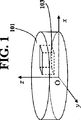
本明細書中で使用する場合、「屈折率の変動」または「屈折率変動」または「Δn」という用語は、約633nm(He−Neレーザー)において干渉法を用いて所定の方向に沿ってガラス材料またはガラス光学部材の光軸に垂直な平面内で測定したときの屈折率の最大変動を意味する(以下に示されるようにティルトおよびピストンの影響を取り除く)。当業者により一般に実施されているように、特定の方向に沿った屈折率変動を考察する場合、ティルトおよびピストンの影響は取り除かれる。したがって、本出願の目的の範囲内では、特定の方向(たとえば、OVD法を用いて作製されたサンプルの半径方向)に沿った屈折率変動には、ティルトまたはピストンの影響は含まれない。以下に示されるように、典型的には、ガラス光学部材、ガラスブランク、またはガラス材料ピースの光軸は、大きい開口面積を有するガラス部材を得るために、測定された屈折率不均一性が最小になる平面(断面)に垂直になるように選択される。本発明の図面の図1は、xyz直交座標系で示された本発明に係る材料のピースまたはブランクを模式的に示している。ブランク101は、光軸zを有する。軸zに垂直な平面xOyは、ブランクの断面が得られるようにブランク101と交差する。屈折率均一性を測定する場合、取り出されるサンプル(たとえば、図1に示されるサンプル103)は、均一な厚さを有する。断面を横切って測定した場合、ティルトおよびピストンの影響を取り除いた所望の方向(たとえば、OVD法を用いて作製されたサンプルの半径方向または図1に示されるx方向)の屈折率変動は、5ppm未満、好ましくは2ppm未満、より好ましくは1ppm未満である。望ましくは、ティルトおよびピストンの影響を取り除いて独立して測定されたx方向およびy方向の両方向の屈折率変動は、5ppm未満、好ましくは2ppm未満、より好ましくは1ppm未満である。
As used herein, the term “refractive index variation” or “refractive index variation” or “Δn” refers to glass along a given direction using interferometry at about 633 nm (He—Ne laser). It means the maximum variation in refractive index as measured in a plane perpendicular to the optical axis of the material or glass optical member (removing the tilt and piston effects as shown below). As is commonly practiced by those skilled in the art, the effects of tilt and piston are eliminated when considering refractive index variation along a particular direction. Thus, within the purpose of this application, refractive index variation along a particular direction (eg, the radial direction of a sample made using the OVD method) does not include the effect of a tilt or piston. As shown below, typically the optical axis of a glass optical member, glass blank, or piece of glass material has the least measured refractive index non-uniformity in order to obtain a glass member having a large open area. Is selected to be perpendicular to the plane (cross section). FIG. 1 of the drawings of the present invention schematically shows a piece or blank of material according to the present invention shown in an xyz Cartesian coordinate system. The blank 101 has an optical axis z. A plane xOy perpendicular to the axis z intersects the blank 101 so that a cross section of the blank is obtained. When measuring refractive index uniformity, the sample taken (eg,
ガラスの複屈折率は、当技術分野で十分に確立された方法に従って、たとえば、とくに複屈折率を測定するように設計された市販の装置を用いて、633nm(He−Neレーザー)において偏光計により測定される。 The birefringence of the glass is determined by a polarimeter at 633 nm (He-Ne laser) according to methods well established in the art, for example, using a commercially available device specifically designed to measure the birefringence. Measured by
ガラス中のβ−OH、重量ppm単位のOH量、ガラス中のOH濃度の変動、およびガラスの仮想温度のようなパラメーターは、典型的には、ガラスの赤外透過率の測定から誘導可能である。興味深い波長領域は、2〜5μm(5000cm−1〜2000cm−1の周波数範囲)である。FT−IR(フーリエ変換赤外)分光計または分散型赤外分光光度計のいずれかの従来型赤外分光光度計が利用可能である。高空間分解能測定の場合、たとえば、OH濃度の変動を調べる場合、当技術分野で公知のように追加の装置を使用することが可能である。 Parameters such as β-OH in glass, OH amount in ppm by weight, OH concentration variation in glass, and fictive temperature of glass are typically derivable from measuring the infrared transmission of the glass. is there. An interesting wavelength range is 2-5 μm (frequency range of 5000 cm −1 to 2000 cm −1 ). Conventional infrared spectrophotometers can be used, either FT-IR (Fourier transform infrared) spectrometers or dispersive infrared spectrophotometers. In the case of high spatial resolution measurements, additional devices can be used as is known in the art, for example when examining variations in OH concentration.
OH基は、溶融シリカ中では、2.72μmの(3676cm−1)、2.21μm(4525cm−1)、および1.38μm(7246cm−1)の近傍に特性吸収バンドを有する。H2種は、溶融シリカ中では、2.38μm(4135cm−1)に吸収バンドを有する。 OH groups, in the molten silica, the 2.72μm (3676cm -1), having a characteristic absorption band in the vicinity of 2.21μm (4525cm -1), and 1.38μm (7246cm -1). H 2 species has an absorption band at 2.38 μm (4135 cm −1 ) in fused silica.
パラメーターβ−OHは、ガラスマトリックス中のヒドロキシル(OH)の相対線吸収係数または単位経路長あたりの吸収として定義される。それは、次式を用いて計算される:

式中:Tref=4000cm−1のような非吸収波長における基準位置でのサンプルの透過率、TOH=OH吸収ピーク(シリカでは約3676cm−1)におけるサンプルの透過率、およびt=サンプルの厚さ(mm)。この値は、ヒドロキシル濃度に正比例する。 Where: the transmittance of the sample at a reference position at a non-absorbing wavelength such as T ref = 4000 cm −1 , the transmittance of the sample at the T OH = OH absorption peak (about 3676 cm −1 for silica), and t = sample Thickness (mm). This value is directly proportional to the hydroxyl concentration.
mol・リットル−1単位のOH濃度cは、ベール・ランベルトの法則
A=ε・c・b
から誘導される。式中、吸光度A=log(Tref/TOH)、εは、リットル・mol−1・cm−1単位のモル吸光率であり、cは、mol・リットル−1単位の濃度であり、そしてbは、cm単位の経路長(サンプル厚さ)である。
OH concentration c in mol·liter− 1 unit is the Beer-Lambert law A = ε · c · b
Derived from. Where Absorbance A = log (T ref / T OH ), ε is the molar absorptivity in liters · mol −1 · cm −1 units, c is the concentration in mol·liters −1 units, and b is the path length (sample thickness) in cm.
c(mol・リットル−1)=A/(ε・b)
したがって、重量ppm単位のOHの濃度は、ガラスの密度およびOHの分子量データを用いて、mol・リットル−1単位のcから計算可能である。特定の波長における高純度シリカガラスの定数εは、先行技術により取得可能である。
c (mol·liter− 1 ) = A / (ε · b)
Therefore, the concentration of OH in ppm by weight can be calculated from c in mol·liter− 1 units using the density of the glass and the molecular weight data of OH. The constant ε of high purity silica glass at a specific wavelength can be obtained by the prior art.
仮想温度とは、凍結ガラス構造が平衡状態にあるときの温度のことである。Si−O−Si結合角は、仮想温度の関数である。Si−O−Si種の赤外吸収の波長または周波数は、結合角によって異なる。したがって、赤外吸収を用いれば、近似的な仮想温度を決定することができる。仮想温度と吸収周波数との経験的関係は、アガルバル(Agarwal)ら著,シリカガラスの仮想温度を決定するための単純なIR分光法(A simple IR spectroscopic method for determining fictive temperature of silica glasses),非結晶性固体誌(Journal of Non−crystalline Solids),第185巻(1995年),191頁のような先行技術に与えられている。ラマン散乱を用いても、歪んだ環構造に関連付けられるシリカ欠陥の散乱周波数から仮想温度を決定することが可能である。 The fictive temperature is the temperature when the frozen glass structure is in an equilibrium state. The Si—O—Si bond angle is a function of fictive temperature. The wavelength or frequency of infrared absorption of the Si—O—Si species varies depending on the bond angle. Therefore, an approximate virtual temperature can be determined using infrared absorption. An empirical relationship between fictive temperature and absorption frequency is described by Agarwal et al., A simple IR spectroscopic method for determining temperature of nonsilica glass to determine the fictive temperature of silica glass. The Journal of Crystalline Solids (Journal of Non-crystalline Solids), Vol. 185 (1995), p. 191. Even using Raman scattering, it is possible to determine the fictive temperature from the scattering frequency of silica defects associated with a distorted ring structure.
溶融シリカ中の格子間分子H2を測定するための好ましい方法は、ラマン散乱である。ラマン分光測定法は、EEV電荷結合素子(CCD)検出器を備えたホリバ・ジョバンイボン社(HORIBA Jobin Yvon Inc.)製のT64000分光計を用いて得られる。分子/cm3単位の水素分子濃度は、4135cm−1における水素分子散乱ピークから検出される強度(I4135)と800cm−1におけるシリカ散乱ピークの強度(I800)との比、すなわち、レーザーラマンスペクトルのI4135/I800から得た(V.S.コチムチェンコ(V.S.Khotimchenko)ら著,応用分光学(Prikladnoi Spektroskopii),第46巻(第6号),987−997頁(1986年)を参照されたい)。より詳細には、バックグラウンドに対して一次もしくは二次のあてはめを用いてピーク下領域を積分することにより、ピークの強度を求めた。本方法の検出限界が1×10¹⁶分子/cm3であることに注目されたい。 A preferred method for measuring interstitial molecules H 2 in fused silica is Raman scattering. Raman spectroscopy is obtained using a T64000 spectrometer manufactured by HORIBA Jobin Yvon Inc. equipped with an EEV charge coupled device (CCD) detector. Hydrogen molecule concentration of molecules / cm 3 units, the ratio of the intensity of the silica scattering peak at 800 cm -1 and the intensity (I 4135) detected from the hydrogen molecule scattering peak at 4135cm -1 (I 800), i.e., laser Raman Obtained from the spectrum I 4135 / I 800 (V.S. Khotimchenko et al., Applied Spectroscopy, Vol. 46 (No. 6), 987-997 (1986) ) More specifically, the intensity of the peak was determined by integrating the area under the peak using a primary or secondary fit to the background. Note that the detection limit of this method is 1 × 10 16 molecules / cm 3 .
絶対β−OH値は、以上に記載のFTIR法により得られる。測定は、典型的には、約1mmの厚さの非常に薄いガラスピースを介して行われる。OH濃度の変動とは、断面内の特定の方向で測定されたOH濃度の値の差を意味する。特定の方向に沿ったOH濃度の変動を考察する場合、以上の屈折率変動の定義のときと同様に、直線的変化の影響は取り除かれる。本出願におけるOH濃度の変動は、データの一次あてはめ曲線からの測定データの最大偏差として定義される。OVD法を用いて作製された円柱状ガラスの場合、半径方向のOH濃度の変動の計算式は、近似的に以下のように表すことが可能である。OH濃度の測定用のサンプルは、図1中の103として模式的に示される。 The absolute β-OH value is obtained by the FTIR method described above. Measurements are typically made through very thin glass pieces about 1 mm thick. The fluctuation of OH concentration means a difference in values of OH concentration measured in a specific direction in the cross section. When considering the variation of OH concentration along a specific direction, the effect of linear variation is removed, as in the above definition of refractive index variation. The variation in OH concentration in this application is defined as the maximum deviation of the measured data from the data's primary fit curve. In the case of a columnar glass manufactured using the OVD method, the calculation formula for the variation of the OH concentration in the radial direction can be approximately expressed as follows. A sample for measuring the OH concentration is schematically shown as 103 in FIG.
N個のデータ点を含有するデータ集合の場合、任意の半径方向位置riでは、ヒドロキシル濃度は、OHiにより与えられる。ここで、i=1、2、3、...、N−1、N。データ集合は、以下の形の一次関数にあてはめることが可能である:
(OH)fit,i=mri+c [1]
ここで、パラメーターmおよびcは、次の関係式を用いて推定される:
(OH) fit, i = mr i + c [1]
Where the parameters m and c are estimated using the following relation:
次に、以上の関係式(最小二乗あてはめ)を用いて、以下の関係式により一次あてはめ曲線からのデータの最大偏差を推定する:
(ΔOH)max=max[abs(OHi−mri−c)] i=1、2、3、...、N [4]
ガラスサンプルの光軸に垂直な断面内の所与の方向に沿ったOH濃度変動を計算する同方法は、必要な変更を加えれば、任意のガラスブランクに対して使用可能である。たとえば、引き続き図1のサンプル103を例にとると、平面xOyに平行な断面内のx座標の関数としての(軸xの方向に沿った)OH濃度変動は、測定OH濃度データの以上の最小二乗あてはめを用いる計算可能である。望ましくは、軸xおよびyの両方向に沿って独立して測定されたOH濃度変動は、20ppm未満、好ましくは10ppm未満、さらに好ましくは5ppm未満、さらに好ましくは3ppm未満、最も好ましくは1ppm未満である。
Next, using the above relation (the least squares fit), the maximum deviation of the data from the primary fitting curve is estimated by the following relation:
(ΔOH) max = max [abs (OH i −m r i −c)] i = 1, 2, 3,. . . , N [4]
The same method of calculating OH concentration variation along a given direction in the cross section perpendicular to the optical axis of the glass sample can be used for any glass blank, mutatis mutandis. For example, taking the
ガラス材料またはそれから作製されたブランクもしくは光学部材の仮想温度の変動は、材料のバルク全体にわたり測定された値の変動である。 The fictive temperature variation of a glass material or a blank or optical member made therefrom is a variation in the value measured across the bulk of the material.
本発明におけるClおよびFの濃度は、当技術分野で利用可能な従来のマイクロプローブ技術を用いて測定される。本発明におけるNa、K、および他の金属の濃度は、当技術分野で利用可能な従来のICP/MS技術を用いて測定される。Clおよびフッ素の濃度は、典型的には、重量ppmに換算して考察される。金属の濃度は、通常、重量ppbに換算して記述される。 The concentrations of Cl and F in the present invention are measured using conventional microprobe techniques available in the art. The concentrations of Na, K, and other metals in the present invention are measured using conventional ICP / MS techniques available in the art. Cl and fluorine concentrations are typically considered in terms of ppm by weight. The metal concentration is usually described in terms of weight ppb.
本出願では、O2/H2OまたはH2O/O2は、O2もしくはH2Oまたはそれらのさまざまな割合の混合物を意味する。 In the present application, O 2 / H 2 O or H 2 O / O 2 means O 2 or H 2 O or a mixture in various proportions thereof.
本明細書中で使用される局所スート密度とは、スートプリフォームの所与の領域の小さい閉体積内のスートプリフォームの嵩密度を意味する。スート粒子が所与の小体積内に稠密に充填されるほど、局所密度は高くなり、したがって、体積内の気孔率は低くなる。本発明の目的では、高い局所スート密度均一性とは、0.2mmにわたる距離に関して、製造された固結ガラスの光軸に垂直な平面内で測定したときの最大および最小の局所スート密度の差が、スートプリフォームの全スート嵩密度の20%未満または0.2g/cm3未満(いずれか大きい方)であることを意味する。好ましくは、0.2mmにわたる距離に関して、最大および最小の局所スート密度の差は、スートプリフォームの全スート嵩密度の10%未満または0.1g/cm3未満(いずれか大きい方)である。より好ましくは、0.2mmにわたる距離に関して、最大および最小の局所スート密度の差は、スートプリフォームの全スート嵩密度の10%未満である。 As used herein, local soot density refers to the bulk density of the soot preform within a small closed volume of a given region of the soot preform. The denser the soot particles are packed into a given small volume, the higher the local density and thus the lower the porosity within the volume. For the purposes of the present invention, high local soot density uniformity is the difference between the maximum and minimum local soot density as measured in a plane perpendicular to the optical axis of the produced consolidated glass for distances over 0.2 mm. Means less than 20% of the total soot bulk density of the soot preform or less than 0.2 g / cm 3 (whichever is greater). Preferably, for distances over 0.2 mm, the difference between the maximum and minimum local soot density is less than 10% of the total soot bulk density of the soot preform or less than 0.1 g / cm 3 (whichever is greater). More preferably, for distances over 0.2 mm, the difference between the maximum and minimum local soot density is less than 10% of the total soot bulk density of the soot preform.
高純度溶融シリカ材料の光学的挙動のレーザー誘起変化は、広範に研究されてきた。なんら特定の理論により拘束されるものではないが、KrF(248nm)およびArF(193nm)ハイパワーパルスレーザーのフォトンのような高エネルギーフォトンを受けたときにシリカ材料内で以下の光反応が起こりうると考えられる:
以上の反応の模式図にて、≡Si−O・および≡Si・は、色中心である。≡Si・は、約215に吸収ピークを有し、したがって、193nmにおけるレーザー誘起吸収に関係する。これらの反応は、誘導吸収(透過損失)、密度変化、屈折率変化(光屈折)、さらには応力複屈折を引き起こしうると考えられる。誘起される密度変化および屈折率変化は、レーザー誘起波面歪み(LIWFD)に共に寄与する。そのようなLIWFDは、波面の遅れ(膨張)および/または進み(圧縮)でありうる。LIWFDは、レーザー線のフルエンスおよびパルス数に依存することが観測されている。ステッパーレンズやUVスキャナーのような高精度光学系の製造業者にとって、そのような圧縮および/または膨張(とくに非線形または予測不能である場合)ならびにレーザー誘起透過損失は、きわめて望ましくない。 In the schematic diagram of the above reaction, ≡Si—O. And ≡Si. Are color centers. ≡Si · has an absorption peak at about 215 and is therefore related to laser-induced absorption at 193 nm. These reactions are thought to cause induced absorption (transmission loss), density change, refractive index change (light refraction), and stress birefringence. The induced density change and refractive index change both contribute to laser induced wavefront distortion (LIWFD). Such LIWFD can be wavefront lag (expansion) and / or advance (compression). LIWFD has been observed to depend on the fluence and number of pulses of the laser line. For manufacturers of precision optics such as stepper lenses and UV scanners, such compression and / or expansion (especially if nonlinear or unpredictable) and laser-induced transmission loss are highly undesirable.
現在までのところ、光学用途で使用される高純度合成溶融シリカ材料を製造するために、2つの主要な方法が使用される。それらは、スートツーガラス法およびダイレクトツーガラス法である。スートツーガラス法では、シリカスート粒子を炉内で生成し、そしてたとえば外付け気相堆積(OVD)または気相軸付け堆積(VAD)などにより回転表面上に堆積させて多孔質スートプリフォームを形成する。続いて、透明固結高純度溶融シリカ材料を形成するために、スートプリフォームを焼結温度で固結させる。この方法は、光ファイバープリフォームの製造に広く使用されてきた。ダイレクトツーガラス法は、通常、火炎加水分解などによりスートツーガラス法の温度よりも高い温度でシリカスート粒子を形成することを含み、スート粒子は、in situで溶融シリカ材料に固結されるような高温(たとえば約1650℃)で、通常はスート粒子が生成されるのと同一の炉内で、回転テーブルの表面上に堆積される。 To date, two main methods are used to produce high purity synthetic fused silica materials for use in optical applications. They are the soot-to-glass method and the direct-to-glass method. In the soot-to-glass method, silica soot particles are generated in a furnace and deposited on a rotating surface, for example, by external vapor deposition (OVD) or vapor axial deposition (VAD) to form a porous soot preform. To do. Subsequently, the soot preform is consolidated at the sintering temperature to form a transparent consolidated high purity fused silica material. This method has been widely used in the manufacture of optical fiber preforms. The direct-to-glass method usually includes forming silica soot particles at a temperature higher than that of the soot-to-glass method, such as by flame hydrolysis, and the soot particles are consolidated into a fused silica material in situ. At a high temperature (eg about 1650 ° C.), it is usually deposited on the surface of the turntable in the same furnace where the soot particles are produced.
ダイレクトツーガラス法の利点の1つは、比較的高い均一性で大きい溶融シリカブールを製造しうる点であり、そのため、ステッパーレンズのように大型の光学系で使用される大型のブランクを製造することが可能である。ダイレクトツーガラス法では所望の組成および光学特性を有するブールを生成すべく多くの重要な(しばしば絡み合った)プロセス変数を変化させることが困難であるため、現在では、最終製品の特性を変更すべくプロセス条件を意図的に調整しうるスートツーガラス材料を用いて高純度合成シリカガラスを製造することに関心が向けられるようになってきている。 One of the advantages of the direct-to-glass method is that it can produce large fused silica boules with relatively high homogeneity, so it can produce large blanks used in large optics such as stepper lenses. Is possible. Because the direct-to-glass process is difficult to change many important (often intertwined) process variables to produce boules with the desired composition and optical properties, it is now necessary to change the properties of the final product. There is an increasing interest in producing high purity synthetic silica glass using soot-to-glass materials that can intentionally adjust process conditions.
高純度合成溶融シリカ材料を製造するためのスートツーガラス法については、これまでに先行技術で記載されてきた。たとえば、米国特許出願公開第2003/0115905号明細書には、0.1×1016〜4.0×1016分子/cm3の範囲内のH2含有量、125〜450重量ppmの範囲内のOH含有量、5×1016分子/cm3未満のSiH基含有量、および2ppm未満の屈折率不均一性を有する溶融シリカブランクが開示されている。この参考文献では、スートツーガラス法が少なくとも部分的に利用されたことが開示されている。しかしながら、目標の製品を得るために焼結後の均一化処理が必要であることは、この参考文献から明らかである。均一化処理は、特別な均一化装置を用いて2000℃までおよび2000℃超の極高温で固結ガラスの加撚および回転を行うことを必要とする。そのような加撚および回転については、たとえば、欧州特許出願公開第EPA1 673 888に記載されている。したがって、米国特許出願公開第2003/0115905号に準拠して焼結直後(ただし均一化処理の前)に調製されたシリカガラスは、多くの対象用途に必要とされる所要の組成および/または屈折率均一性を有していないことは明らかである。しかしながら、以上で述べたように、そのような高温の加撚および回転は、特殊な装置の使用を必要とし、非常に複雑であり、かなり運転コストがかかる。 Soot-to-glass processes for producing high purity synthetic fused silica materials have been described in the prior art. For example, US 2003/0115905 describes H 2 content in the range of 0.1 × 10 16 to 4.0 × 10 16 molecules / cm 3 , in the range of 125 to 450 ppm by weight. A fused silica blank is disclosed having an OH content of less than 5 × 10 16 molecules / cm 3 and a SiH group content of less than 2 ppm and a refractive index non-uniformity of less than 2 ppm. This reference discloses that the soot-to-glass method was at least partially utilized. However, it is clear from this reference that a homogenization treatment after sintering is necessary to obtain the target product. The homogenization treatment requires that the consolidated glass be twisted and rotated up to 2000 ° C. and above 2000 ° C. using a special homogenizer. Such twisting and rotation is described, for example, in European Patent Application Publication No. EPA1 673 888. Thus, silica glass prepared immediately after sintering (but before homogenization) according to US 2003/0115905 has the required composition and / or refraction required for many target applications. It is clear that there is no rate uniformity. However, as mentioned above, such high temperature twisting and rotation requires the use of special equipment, is very complex and is quite expensive to operate.
驚くべきことに、本発明者らは、固結ガラスの焼結後の均一化処理を必要とすることなくスートツーガラス法を用いて高純度合成溶融シリカ材料を製造した。合成シリカガラスは、組成要件および特性要件、とくに、ガラスの光軸に垂直な平面内の屈折率均一性要件を備える。合成シリカガラス材料自体は、本発明の第1の態様を構成する。本発明に係るシリカガラスは、材料の光軸に垂直な平面内で測定したときに、20ppm未満、好ましくは10ppm未満、最も好ましくは5ppm未満のOH濃度変動を有することが特徴である。ガラスは、塩素、フッ素、および他のドーパントでドープ可能である。望ましくは、そのような他のドーパントは、OH濃度変動が以上に記載の要件を満たす平面と同一の平面内に実質的に均一に分布する。そのような平面内の組成の均一性の結果として、本発明に係るガラスは、同一平面内で高い屈折率均一性を有する。望ましくは、同一平面内のΔnは、5ppm未満、好ましくは2ppm未満、より好ましくは1ppm未満である。 Surprisingly, the inventors have produced a high purity synthetic fused silica material using the soot-to-glass method without the need for homogenization after sintering of the consolidated glass. Synthetic silica glass has compositional and property requirements, particularly refractive index uniformity requirements in a plane perpendicular to the optical axis of the glass. The synthetic silica glass material itself constitutes the first aspect of the present invention. The silica glass according to the invention is characterized by having an OH concentration variation of less than 20 ppm, preferably less than 10 ppm, most preferably less than 5 ppm when measured in a plane perpendicular to the optical axis of the material. The glass can be doped with chlorine, fluorine, and other dopants. Desirably, such other dopants are distributed substantially uniformly in the same plane where the OH concentration variation meets the requirements described above. As a result of such in-plane compositional uniformity, the glass according to the invention has a high refractive index uniformity in the same plane. Desirably, Δn in the same plane is less than 5 ppm, preferably less than 2 ppm, more preferably less than 1 ppm.
適正量のH2の存在は、ガラス中の酸素欠乏中心の形成の抑制ならびにレーザー誘起吸収およびLIWFDの減少を行うように機能しうるので、本発明に係るガラスのいくつかの実施形態では、シリカガラスは、1×10¹⁵〜5×10¹⁸分子/cm3の量でH2を含む。 In some embodiments of the glass according to the invention, the presence of the proper amount of H 2 can function to suppress the formation of oxygen-deficient centers in the glass and to reduce laser-induced absorption and LIWFD. The glass contains H 2 in an amount of 1 × 10 15 to 5 × 10 18 molecules / cm 3 .
塩素、アルカリ金属、アルカリ土類金属、および遷移金属の存在はすべて、193nmにおける透過損失をもたらす。したがって、ガラス中の塩素レベルを50ppm未満に制御し、かつアルカリ金属、アルカリ土類金属、および遷移金属の量をすべて、10ppb未満、好ましくは1ppb未満に制御することが望ましい。 The presence of chlorine, alkali metals, alkaline earth metals, and transition metals all lead to transmission losses at 193 nm. Therefore, it is desirable to control the chlorine level in the glass to less than 50 ppm and to control all the amounts of alkali metal, alkaline earth metal, and transition metal to less than 10 ppb, preferably less than 1 ppb.
ガラス内で193nmにおけるレイリー散乱、複屈折、および屈折率均一性をさらに減少させるために、本発明に係るガラス材料は、800〜1200℃の低い仮想温度を有することが望ましい。また、ガラス中の局所密度変動を最小限に抑えるために、本発明に係るガラスは、50℃未満、好ましくは10℃未満の仮想温度変動を有することが望ましい。 In order to further reduce Rayleigh scattering, birefringence, and refractive index uniformity at 193 nm in the glass, it is desirable for the glass material according to the present invention to have a low fictive temperature of 800-1200 ° C. Also, in order to minimize local density fluctuations in the glass, it is desirable that the glass according to the present invention has a fictive temperature fluctuation of less than 50 ° C, preferably less than 10 ° C.
本発明の第2の態様は、本発明に係るシリカガラス材料で作製された光学ガラス部材である。この部材は、本発明に係る材料の軸に平行な光軸を有し、それに垂直な平面内のOH濃度変動は、20重量ppm未満である。望ましくは、本発明に係る光学ガラス部材は、193nmにおいて、99.65%/cm超、好ましくは99.70%/cm超、より好ましくは99.75%/cm超、最も好ましくは99.80%/cm超の内部透過率を有する。 The second aspect of the present invention is an optical glass member made of the silica glass material according to the present invention. This member has an optical axis parallel to the axis of the material according to the present invention, and the OH concentration variation in a plane perpendicular thereto is less than 20 ppm by weight. Desirably, the optical glass member according to the present invention has more than 99.65% / cm, preferably more than 99.70% / cm, more preferably more than 99.75% / cm, most preferably 99.80 at 193 nm. It has an internal transmittance of more than% / cm.
本発明の第3の態様は、新規なスートツーガラス法に関する。本方法の工程(i)において、典型的には、ケイ素前駆体化合物の火炎加水分解プロセスにより、スート粒子が提供される。O2と共に燃焼する水素、CH4などの火炎中に、SiCl4や有機ケイ素化合物(たとえばOMCTS(オクタメチルシクロテトラシロキサン))などのようなケイ素前駆体化合物を導入することが可能であり、それにより、シリカスートが形成される。工程(i)は、プラズマ支援でありうる。工程(ii)において、典型的な外付け気相堆積(OVD)法または気相軸付け堆積(VAD)法のときのように、支持コアケイン上またはマンドレル上にシリカスートを堆積させて多孔質体を形成することが可能である。マンドレルを使用する場合、通常、堆積後にそれを除去して中空円筒状多孔質スート体を形成し、その後、工程(iv)における固結に付す。多孔質スート体は、工程(iv)としてまたはオプションの事前の精製を併用して固結可能である。他の選択肢として、「溶融シリカガラスおよびドープ溶融シリカガラスの製造方法」という名称のハーディナ(Hrdina)らに付与された米国特許第6,606,883号明細書(その内容は、参考になるので、参照により本明細書に組み入れられるものとする)の教示に従って、スートプリフォームを形成することが可能である。この特許文献によれば、平面表面上にシリカスート粒子を堆積させることにより、フラットな多孔質シリカスートプリフォームを形成することが可能である。本出願では、このプリフォーム堆積法をこれ以降で「平面堆積」と記す。有利には、より均一なスートプリフォーム体を製造しうるように、平面堆積表面の回転および振動を行う。 The third aspect of the present invention relates to a novel soot-to-glass method. In step (i) of the method, soot particles are typically provided by a flame hydrolysis process of a silicon precursor compound. It is possible to introduce silicon precursor compounds such as SiCl 4 and organosilicon compounds (eg OMCTS (octamethylcyclotetrasiloxane)) into a flame such as hydrogen, CH 4 , which burns with O 2 , As a result, silica soot is formed. Step (i) can be plasma assisted. In step (ii), as in typical external vapor deposition (OVD) or vapor phase axial deposition (VAD) methods, silica soot is deposited on a supporting core cane or mandrel to form a porous body. It is possible to form. When a mandrel is used, it is usually removed after deposition to form a hollow cylindrical porous soot body and then subjected to consolidation in step (iv). The porous soot body can be consolidated as step (iv) or in combination with optional prior purification. Another option is US Pat. No. 6,606,883 to Hrdina et al. Entitled “Method for Producing Fused Silica Glass and Doped Fused Silica Glass,” the contents of which are hereby incorporated by reference. , Which is incorporated herein by reference), soot preforms can be formed. According to this patent document, it is possible to form a flat porous silica soot preform by depositing silica soot particles on a flat surface. In this application, this preform deposition method will be referred to as “planar deposition” hereinafter. Advantageously, the planar deposition surface is rotated and vibrated so that a more uniform soot preform body can be produced.
使用する堆積法のいかんにかかわらず、工程(ii)で作製されるプリフォームの局所スート密度は、十分に均一であることが重要である。本発明の多くの実施例および比較例と関連させて以下に論じられるように、固結前のプリフォームの初期局所スート密度は、最終組成均一性、特定的には固結ガラス中のOH濃度均一性を決定する重要な因子の1つである。したがって、本発明では、プリフォームの0.2mmにわたる距離に関する局所スート密度変動は、全スートプリフォームの全嵩密度の20%未満または0.2g/cm3未満(いずれか大きい方)であることが必要とされる。好ましくは、プリフォームの0.2mmにわたる距離に関する局所スート密度変動は、全スートプリフォームの全嵩密度の10%未満または0.1g/cm3未満(いずれか大きい方)である。高い初期局所スート密度均一性を得るために、一方法として、本発明に係る方法の工程(i)および(ii)において、バーナーの振動の無作為化または半無作為化を行う。これについては、本発明の実施例および比較例と関連させて以下でさらに説明する。スート堆積の均一性を改良するために使用しうる技術、ストラテジー、および装置は、たとえば、アボット(Abbott)らに付与された米国特許第5,211,732号の明細書(その内容は、参考になるので、参照により本明細書に組み入れられるものとする)に開示されている。 Regardless of the deposition method used, it is important that the local soot density of the preform produced in step (ii) is sufficiently uniform. As discussed below in connection with many examples and comparative examples of the present invention, the initial local soot density of the preform prior to consolidation is the final composition uniformity, specifically the OH concentration in the consolidated glass. It is one of the important factors that determine uniformity. Thus, in the present invention, the local soot density variation with distance over 0.2 mm of the preform is less than 20% of the total bulk density of the entire soot preform or less than 0.2 g / cm 3 (whichever is greater). Is needed. Preferably, the local soot density variation with distance over 0.2 mm of the preform is less than 10% of the total bulk density of the entire soot preform or less than 0.1 g / cm 3 (whichever is greater). In order to obtain a high initial local soot density uniformity, as one method, the burner vibration is randomized or semi-randomized in steps (i) and (ii) of the method according to the invention. This will be further described below in connection with the examples and comparative examples of the present invention. Techniques, strategies, and apparatus that can be used to improve soot deposition uniformity are described, for example, in US Pat. No. 5,211,732 issued to Abbott et al. And thus incorporated herein by reference).
バーナーを介して供給される前駆体化合物およびO2の流量の比の急激な変化は、最終固結ガラスにおいて望ましくない局所スート密度変動および脈理をもたらす可能性があることが見出された。したがって、好ましくは、工程(i)において、ケイ素含有前駆体化合物の火炎加水分解により、シリカスート粒子が提供され、工程(ii)において、スート粒子を回転支持表面に堆積させることにより、スートプリフォームが形成される。ここで、工程(i)および(ii)において、スートレイダウンの初期段階でバーナーを介して加水分解火炎に提供される前駆体化合物およびO2の流量の変化率の比は、それらが実質的に同時に安定化する前、前駆体化合物およびO2が増加する時、実質的に一定に保持される。通常、火炎加水分解プロセスのスートレイダウンの初期段階では、ケイ素前駆体化合物(「SPC」)およびO2の流量は、徐々に、理想的には時間に対してほぼ直線的に、増大する。ケイ素前駆体化合物およびO2の流量の変化率は、以下のように表現することが可能である:
式中、FspcおよびFO2は、それぞれ、ケイ素前駆体化合物およびO2の流量であり、tは時間であり、そしてCRFSPCおよびCRFO2は、それぞれ、ケイ素前駆体化合物およびO2の流量の変化率である。したがって、流量の変化率の比(Rc)は、以下のようになる:
したがって、本発明に係る方法のこの好ましい実施形態では、ケイ素前駆体化合物およびO2の流量が増大する時、それらが本質的に同時に安定化する前、スートレイダウンの初期段階で、Rcは本質的には一定に保持される。「本質的には一定」とは、Rcの変動が5%未満、好ましくは3%未満、より好ましくは1%未満であることを意味する。本発明に係る方法の他の好ましい実施形態では、加水分解火炎に提供される前駆体化合物およびO2の流量の比は、実質的に一定に保持され、これは、以下のように表現される:
好ましい実施形態では、工程(i)において、少なくとも1台のバーナーを介してケイ素含有前駆体化合物を火炎加水分解することにより、スート粒子が提供され、工程(ii)において、スート粒子を回転支持表面上に堆積させることにより、スートプリフォームが形成される。ここで、支持表面上に堆積されたスートが高い局所スート密度均一性を有するように、バーナーの位置は、支持表面に対してパターン状に振動させる。好ましくは、パターンは、半無作為または無作為である。実施例と関連させて以下に記載されるように、OVD法では図12に示されるようなバーナー振動により、望ましくないレベルの局所スート密度変動を生じることが判明した。しかしながら、図17に示されるような半無作為化振動パターンでは、はるかにより良好な局所スート密度が得られるので、固結ガラス中のOH濃度均一性は改良される。本出願において本明細書中で使用する場合、「半無作為化パターンまたは無作為化パターン」という用語は、スート堆積表面に対するバーナーの移動の1サイクル(たとえば、図17の移動回数1〜45)で有意な支持表面の異なる領域におけるバーナーの滞留時間および通過時間が本質的に均一になるのに十分な程度に無作為である振動パターンを意味する。 In a preferred embodiment, in step (i), soot particles are provided by flame hydrolysis of the silicon-containing precursor compound via at least one burner, and in step (ii) the soot particles are provided on a rotating support surface. By depositing on top, a soot preform is formed. Here, the position of the burner is vibrated in a pattern relative to the support surface so that the soot deposited on the support surface has a high local soot density uniformity. Preferably, the pattern is semi-random or random. As described below in connection with the examples, the OVD method has been found to cause undesirable levels of local soot density fluctuations due to burner oscillation as shown in FIG. However, the semi-randomized vibration pattern as shown in FIG. 17 results in much better local soot density, thus improving the OH concentration uniformity in the consolidated glass. As used herein in this application, the term “semi-randomized pattern or randomized pattern” refers to one cycle of burner movement relative to the soot deposition surface (eg, 1 to 45 movements in FIG. 17). Means a vibration pattern that is random enough to make the residence time and transit time of the burner in different regions of the support surface significantly uniform.
スートプリフォームの精製は、塩素処理などのような当技術分野で公知の方法を用いて実施可能である。SiCl4のような塩素含有ケイ素前駆体化合物を用いてプリフォームを形成する場合または塩素を用いてプリフォームを精製する場合、固結前にプリフォームから塩素を除去することが望まれることもある。塩素除去は、O2、H2O、フッ素含有化合物、Br含有化合物など、ならびにそれらの相溶性混合物および組合せ(ただし、これらに限定されるものではない)をはじめとするさまざまなタイプの気体を用いて、実施可能である。 The soot preform can be purified using methods known in the art such as chlorination. When forming a preform using a chlorine-containing silicon precursor compound such as SiCl 4 or purifying the preform using chlorine, it may be desirable to remove chlorine from the preform prior to consolidation. . Chlorine removal involves various types of gases, including but not limited to O 2 , H 2 O, fluorine-containing compounds, Br-containing compounds, and the like, and compatible mixtures and combinations thereof. And can be implemented.
固結(焼結)工程(iv)は、通常、ヘリウムおよび/またはアルゴンのような不活性ガスの存在下で行われる。比較的高いOH濃度、たとえば、50ppm超のOH濃度を有するシリカガラスを得るために、H2Oの存在下でスートプリフォームを固結することが望ましい。以下で論述されように、シリカガラス中の最終OH濃度は、部分的には、固結雰囲気中のH2Oの分圧により決定される。H2、O2、フッ素含有化合物などのような他の気体の存在下で固結を行いうることが除外されるものではない。 The consolidation (sintering) step (iv) is usually performed in the presence of an inert gas such as helium and / or argon. It is desirable to consolidate the soot preform in the presence of H 2 O in order to obtain a silica glass having a relatively high OH concentration, for example an OH concentration greater than 50 ppm. As discussed below, the final OH concentration in silica glass is determined in part by the partial pressure of H 2 O in the consolidated atmosphere. It is not excluded that consolidation can be performed in the presence of other gases such as H 2 , O 2 , fluorine-containing compounds and the like.
多孔質ガラスプリフォームの固結の後、凝縮ガラスを水素の存在下の処理にさらに付すことが可能であり、この場合、H2分子は、所望のレベルまでガラス体中に充填される。 After consolidation of the porous glass preform, the condensed glass can be further subjected to treatment in the presence of hydrogen, in which case H 2 molecules are loaded into the glass body to the desired level.
プリフォームが固結される炉の温度−時間プロファイルは、固結ガラスの品質にきわめて重要である。温度上昇速度は、固結ガラスの最終組成プロファイルを制御するための重要なプロセス手段である。1200℃のような低すぎる温度で固結することは、理論上可能であるとはいえ、ガラスを完全に固結するのに時間がかかりすぎるので、一般的には、実用的ではない。温度が高いほど、固結は、より迅速になる。たとえば、1650℃では、ダイレクトツーガラス炉内で製造されるスート粒子は、溶融シリカガラスの状態にin situで固結される。しかしながら、以下の考察から明らかなように、固結(焼結)時、温度上昇速度が速すぎると、ガラス中に温度勾配を生じる傾向があるので、スートプリフォーム中に組成勾配を生じたり、プリフォーム中のさまざまな領域で異なる焼結速度を生じたりして、結果的に、組成勾配を引き起こす。組成勾配は、通常、固結ガラス中に屈折率変動を引き起こす。低い温度上昇速度では、スートプリフォーム全体にわたる温度勾配およびプリフォームと雰囲気との間の温度勾配は、生じにくくなるかまたはたとえ存在したとしても小さいので、雰囲気は、プリフォーム全体にわたりスート粒子と平衡状態になる。このことは、スートプリフォーム中にH2Oを一様に分布させるうえでとくに重要である。以下に論じられるように、スートプリフォーム中のH2Oの一様分布は、固結ガラス中のOH濃度均一性に重要である。 The temperature-time profile of the furnace in which the preform is consolidated is critical to the quality of the consolidated glass. The temperature rise rate is an important process tool for controlling the final composition profile of the consolidated glass. While it is theoretically possible to consolidate at a temperature as low as 1200 ° C., it is generally not practical because it takes too much time to fully consolidate the glass. The higher the temperature, the faster the consolidation. For example, at 1650 ° C., soot particles produced in a direct-to-glass furnace are consolidated in situ into a fused silica glass. However, as is clear from the following considerations, at the time of consolidation (sintering), if the temperature increase rate is too fast, there is a tendency to generate a temperature gradient in the glass, so a composition gradient is generated in the soot preform, This can result in different sintering rates at different regions in the preform, resulting in a compositional gradient. The composition gradient usually causes refractive index fluctuations in the consolidated glass. At low temperature rise rates, the temperature is balanced with soot particles throughout the preform because the temperature gradient across the soot preform and the temperature gradient between the preform and the atmosphere are less likely to occur or, if present, small. It becomes a state. This is particularly important for the uniform distribution of H 2 O in the soot preform. As discussed below, the uniform distribution of H 2 O in the soot preform is important for the OH concentration uniformity in the consolidated glass.
したがって、プリフォームを1600℃までのそのような高い温度まで昇温するのであれば、1000〜1600℃において0.4℃/分未満の温度上昇速度を保持することが望ましい。好ましくは、1150〜1450℃において、温度上昇速度は、0.2℃/分未満に保持される。さらに望ましくは、固結ガラス中の高い組成均一性を得るために、最終緻密化前に1150〜1300℃においてプリフォームを最初に恒温で少なくとも1時間保持する。好ましくは、プリフォームは、5時間超(ただし200時間未満)の時間にわたり1150〜1300℃の温度で恒温に保持される。 Therefore, if the preform is heated to such a high temperature up to 1600 ° C., it is desirable to maintain a temperature rise rate of less than 0.4 ° C./min at 1000-1600 ° C. Preferably, at 1150-1450 ° C, the rate of temperature rise is kept below 0.2 ° C / min. More desirably, to obtain high composition uniformity in the consolidated glass, the preform is first held at a constant temperature for at least 1 hour at 1150-1300 ° C. prior to final densification. Preferably, the preform is held at a constant temperature of 1150-1300 ° C. for a time greater than 5 hours (but less than 200 hours).
本発明者らは、焼結後の均一化工程を用いることなくスートツーガラス法により溶融シリカガラスサンプル物質を調製した。これらのサンプルは、光ファイバープリフォームを製造するために慣例的に使用されてきた外付け気相堆積(OVD)法を用いて形成された。したがって、火炎加水分解により生成されたシリカスート粒子をコアガラスケイン上に堆積させた。堆積後、マンドレルを除去して多孔質スートプリフォームを形成し、続いて、これを固結炉内で固結させて中空円筒形状を有する溶融シリカガラスにした。図2は、10ppm未満のOHを有して調製されたサンプルのうちの1つの半径方向塩素プロファイル(マイクロプローブによる)を示している。この図に明確に示されるように、マンドレルの表面からの距離が長くなるほど、固結ガラス中の塩素濃度は低くなる。図3は、図2と同一のサンプルの半径方向断面(すなわち、円筒状プリフォームの軸に垂直な断面)内で測定された屈折率変化と塩素濃度との相関を示す図である。この図は、屈折率変動が塩素濃度変動に依存することを明確に示している。図4は、5ppm未満の塩素濃度を有する他のサンプルの半径方向OH濃度プロファイル(FT−IRによる)を示している。このサンプルでは、マンドレルの表面からの距離が長くなるほど、固結ガラス中のOH濃度が低くなる。図5は、図4と同一のサンプルについて半径方向断面内で測定された半径方向OH濃度と屈折率変動との相関を示している。屈折率変動がOH濃度変動に依存することは、この図から明らかである。これらのサンプルを調べることから、本発明者らは、屈折率均一性が組成均一性に大きく依存することを突き止めた。特定的には、低い塩素濃度を有する固結シリカガラスでは、断面内のOH濃度の均一性は、屈折率均一性を決定する重要な組成因子である。 The inventors prepared a fused silica glass sample material by the soot-to-glass method without using a homogenization step after sintering. These samples were formed using an external vapor deposition (OVD) method that has been routinely used to produce optical fiber preforms. Therefore, silica soot particles produced by flame hydrolysis were deposited on the core glass cane. After deposition, the mandrel was removed to form a porous soot preform, which was subsequently consolidated in a consolidation furnace to form a fused silica glass having a hollow cylindrical shape. FIG. 2 shows the radial chlorine profile (by microprobe) of one of the samples prepared with less than 10 ppm OH. As clearly shown in this figure, the longer the distance from the mandrel surface, the lower the chlorine concentration in the consolidated glass. FIG. 3 is a diagram showing the correlation between the refractive index change and the chlorine concentration measured in the radial section of the same sample as in FIG. 2 (that is, the section perpendicular to the axis of the cylindrical preform). This figure clearly shows that the refractive index variation depends on the chlorine concentration variation. FIG. 4 shows the radial OH concentration profile (by FT-IR) of another sample having a chlorine concentration of less than 5 ppm. In this sample, the longer the distance from the surface of the mandrel, the lower the OH concentration in the consolidated glass. FIG. 5 shows the correlation between the radial OH concentration measured in the radial section and the refractive index variation for the same sample as FIG. It is clear from this figure that the refractive index variation depends on the OH concentration variation. From examining these samples, the inventors have determined that refractive index uniformity is highly dependent on composition uniformity. Specifically, in consolidated silica glass having a low chlorine concentration, the uniformity of the OH concentration in the cross section is an important composition factor that determines the refractive index uniformity.
溶融シリカガラス中に存在する水は、一般的には、β−OH(≡Si−OH)の形態をとる。本発明者らは、かなり多くの精巧にデザインされた実験を行うことから、スート堆積工程およびプリフォーム固結工程でプロセス条件を注意深く制御することにより、固結ガラス中の高いOH濃度均一性を達成しうることを見出した。固結ガラス中のOH濃度均一性を決定する2つの最も重要な因子は、堆積されたスートプリフォーム中の局所スート密度変動および固結工程における熱履歴である。一般的にいえば、スートプリフォーム中の高い局所スート密度均一性は、固結ガラス中の高い屈折率均一性を取得する必要条件である。緩速な温度上昇速度、好ましくは、固結工程の特定の温度ゾーンにおけるスートプリフォームの恒温処理は、固結ガラス中の均一OH濃度をもたらす。 The water present in the fused silica glass is generally in the form of β-OH (≡Si—OH). Since we perform quite a few well-designed experiments, we carefully controlled the process conditions during the soot deposition and preform consolidation steps to achieve high OH concentration uniformity in the consolidated glass. I found that it can be achieved. The two most important factors that determine the OH concentration uniformity in the consolidated glass are the local soot density variation in the deposited soot preform and the thermal history in the consolidation process. Generally speaking, high local soot density uniformity in the soot preform is a necessary condition for obtaining high refractive index uniformity in the consolidated glass. A slow temperature rise rate, preferably isothermal treatment of the soot preform in a particular temperature zone of the consolidation process, results in a uniform OH concentration in the consolidated glass.
固結ガラス中のOH濃度均一性に及ぼす温度上昇速度の影響を調べるために、一連のスートプリフォームをさまざまな速度で焼結し、得られた溶融シリカガラスのOH濃度変動を測定した。プリフォームは、ヘリウムのみまたはヘリウム/H2O混合物の雰囲気中で焼結させた。図6は、4つのサンプル(サンプル番号6.1、6.2、6.3、および6.4)の半径方向OH濃度プロファイルの結果を示している。サンプル番号6.1、6.2、6.3、および6.4は、それぞれ、0.19、0.50、2.2、および3.0℃/分で固結させた。この図から、焼結時の温度上昇速度を緩速化することにより、サンプルを横切る半径方向OH濃度が有意に平坦化されることは明らかである。図7は、異なる方法でデータをプロットして図6のデータを示したものである。この場合、水平軸は、焼結時の温度上昇速度を表し、鉛直軸は、サンプルの半径を横切るOH濃度の最大差を表している。このプロットは、ヘリウムのみまたはヘリウム/H20混合物の雰囲気中での焼結時に種々の温度上昇速度下で固結された複数のSiO2スートプリフォームサンプルのデータを含有する。このプロットから、焼結時の温度上昇速度は、サンプルを横切るOH濃度プロファイル(したがって屈折率)を制御する主要なプロセス手段であることが確認される。この試験はOH濃度プロファイルのみに関するものであるが、Cl、Fなどのような他の組成プロファイルについても同様に焼結時の温度上昇速度を制御することにより制御可能であると適切に推論される。 In order to investigate the influence of the temperature rise rate on the OH concentration uniformity in the consolidated glass, a series of soot preforms were sintered at various speeds, and the OH concentration variation of the obtained fused silica glass was measured. The preform was sintered in an atmosphere of helium alone or a helium / H 2 O mixture. FIG. 6 shows the results of radial OH concentration profiles for four samples (sample numbers 6.1, 6.2, 6.3, and 6.4). Sample numbers 6.1, 6.2, 6.3, and 6.4 were consolidated at 0.19, 0.50, 2.2, and 3.0 ° C./min, respectively. From this figure, it is clear that by reducing the rate of temperature rise during sintering, the radial OH concentration across the sample is significantly flattened. FIG. 7 shows the data of FIG. 6 by plotting the data in different ways. In this case, the horizontal axis represents the rate of temperature increase during sintering, and the vertical axis represents the maximum difference in OH concentration across the radius of the sample. This plot contains data for multiple SiO 2 soot preform samples consolidated at various temperature rise rates during sintering in an atmosphere of helium alone or a helium / H 2 O mixture. This plot confirms that the rate of temperature rise during sintering is the primary process tool for controlling the OH concentration profile (and hence the refractive index) across the sample. Although this test relates only to the OH concentration profile, it is reasonably reasoned that other composition profiles such as Cl, F, etc. can be controlled by controlling the rate of temperature rise during sintering as well. .
図8は、5つの異なるシリカ物品(サンプル番号8.1,8.2,8.3,8.4,および8.5)に対する時間−温度炉プロファイル固結条件を示している。ブランクは、ヘリウムのみまたはヘリウム/H2O混合物の雰囲気で焼結させた。固結ガラスサンプルは、FTIRにより分析した。得られた半径方向OH濃度変動プロファイルは、以下に示されるとおりである:
サンプル番号8.1: 107ppm
サンプル番号8.2: 117ppm
サンプル番号8.3: 58ppm
サンプル番号8.4: 75ppm
サンプル番号8.5: 11ppm
図6および7に示されるより少ないサンプルの場合と同様に、この場合のデータでも、とくに1200℃超で、焼結時の温度上昇速度を減少させることにより、半径方向OH均一性が改良されることが明確に示される。そのほか、ある時間にわたり1300℃にスートを保持することにより、半径方向均一性がさらに改良され、しかもこの1300℃での保持が、1300℃超で徐々に変化させるよりも決定的に重要であることが判明した。さらに、1275℃における恒温保持が半径方向OH均一性をさらに改良することが判明した。なんら特定の理論により拘束されるものではないが、これらの改良は、シリカスートが焼結の臨界期にシリカ物品の半径方向距離を横切って均一な温度およびH2O濃度に到達した結果であると考えられる。また、すべてのドーパントの濃度が均一に分布するようにするには、ドーパント(OH、Cl、F)濃度に依存して、最適温度プロファイルが変化すると予想される。
FIG. 8 shows the time-temperature furnace profile consolidation conditions for five different silica articles (sample numbers 8.1, 8.2, 8.3, 8.4, and 8.5). The blank was sintered in an atmosphere of helium alone or a helium / H 2 O mixture. The consolidated glass sample was analyzed by FTIR. The resulting radial OH concentration variation profile is as shown below:
Sample number 8.1: 107ppm
Sample number 8.2: 117ppm
Sample number 8.3: 58ppm
Sample number 8.4: 75 ppm
Sample number 8.5: 11 ppm
As in the case of the smaller samples shown in FIGS. 6 and 7, this data improves radial OH uniformity by reducing the rate of temperature rise during sintering, especially above 1200 ° C. Is clearly shown. In addition, holding the soot at 1300 ° C for some time further improves the radial uniformity, and this holding at 1300 ° C is more critical than gradually changing above 1300 ° C. There was found. Furthermore, it has been found that isothermal holding at 1275 ° C. further improves the radial OH uniformity. Without being bound by any particular theory, these improvements are the result of silica soot reaching a uniform temperature and H 2 O concentration across the radial distance of the silica article during the critical period of sintering. Conceivable. Moreover, in order to make the concentration of all the dopants uniformly distributed, the optimum temperature profile is expected to change depending on the dopant (OH, Cl, F) concentration.
本発明者らはまた、固結ガラス中の半径方向OH濃度プロファイルに及ぼす局所スート密度変動の影響を調べた。 We also investigated the effect of local soot density variation on the radial OH concentration profile in consolidated glass.
図9は、0.19℃/分の速度で焼結させたスートプリフォームサンプルの半径方向OH濃度プロファイルおよび初期半径方向スート密度の結果を示している。焼結時のSiO2スート収縮の結果としてOH濃度と初期スート密度との直接的な比較を行うために、水平軸は、正規化半径方向距離でプロットされている。初期スートサンプルは、厚さ50mmであり、固結スート(ガラス)サンプルは、厚さ27mmであった。上側の曲線は、OH濃度曲線であり、下側の曲線は、局所スート密度を示している。スートプリフォームの内縁から出発して、スート密度は減少し、焼結SiO2ガラス中の得られたOHは増大することが、データから明らかである。次に、スート密度が増大するにつれて、焼結ガラス中のOH濃度プロファイルは減少することがわかる。また、初期スート密度がより平坦になるにつれて、焼結ガラス中の得られたOH濃度プロファイルは、より均一になる。スート密度は、SiO2堆積時のCH4/O2/SiCl4(またはOMCTS)比およびプロセス中のいずれかの時間点でバーナーが留まる滞留時間を変化させることにより制御された。米国特許第5,211,732号明細書に教示されるように、滞留時間が長くなるほど、基板の温度が高くなり、CH4+O2/SiCl4(またはOMCTS)流量が多くなって、堆積されるスート密度は増大する。なんら特定の理論により拘束されるものではないが、本発明者らは、局所スート密度に対するOH濃度のこの依存性が次のように説明されると考えている。すなわち、スート密度は、スート表面積に反比例し;ガラスに組み込まれるOHは、初期スート表面積および固結炉雰囲気中のH2O分圧に比例する。スートプリフォーム中のスート粒子の周囲のH2O濃度が焼結時に均一でありかつ焼結雰囲気中のH2Oと平衡状態にあると仮定すると、焼結雰囲気中の所与のH2O濃度において、スート表面積が大きくなるほど(したがってプリフォーム中の局所スート密度が小さくなるほど)、固結ガラス中に組み込まれるOHの濃度は、高くなる。 FIG. 9 shows the radial OH concentration profile and initial radial soot density results for a soot preform sample sintered at a rate of 0.19 ° C./min. In order to make a direct comparison of OH concentration and initial soot density as a result of SiO 2 soot shrinkage during sintering, the horizontal axis is plotted with normalized radial distance. The initial soot sample was 50 mm thick and the consolidated soot (glass) sample was 27 mm thick. The upper curve is the OH concentration curve, and the lower curve shows the local soot density. It is clear from the data that starting from the inner edge of the soot preform, the soot density decreases and the resulting OH in the sintered SiO 2 glass increases. Next, it can be seen that as the soot density increases, the OH concentration profile in the sintered glass decreases. Also, as the initial soot density becomes flatter, the resulting OH concentration profile in the sintered glass becomes more uniform. The soot density was controlled by varying the CH 4 / O 2 / SiCl 4 (or OMCTS) ratio during SiO 2 deposition and the residence time at which the burner stayed at any point in the process. As taught in US Pat. No. 5,211,732, the longer the residence time, the higher the temperature of the substrate and the higher the CH 4 + O 2 / SiCl 4 (or OMCTS) flow rate, which is deposited. Soot density increases. Without being bound by any particular theory, the inventors believe that this dependence of OH concentration on local soot density is explained as follows. That is, the soot density is inversely proportional to the soot surface area; the OH incorporated into the glass is proportional to the initial soot surface area and the H 2 O partial pressure in the consolidation furnace atmosphere. Assuming that the H 2 O concentration around the soot particles in the soot preform is uniform during sintering and in equilibrium with H 2 O in the sintering atmosphere, a given H 2 O in the sintering atmosphere In concentration, the higher the soot surface area (and hence the lower the local soot density in the preform), the higher the concentration of OH incorporated in the consolidated glass.
図10は、0.19℃/分の温度上昇速度で焼結させた他のシリカスートプリフォームサンプルに対する類似のプロットを示している。ゼロ正規化半径方向距離(サンプルの内部)から出発して、初期スート密度は、かなり平坦であることがわかり、対応するOH濃度プロファイルもまた、かなり平坦である。スート密度が急激に増大するとき、得られるOH濃度プロファイルは、低下することがわかり、逆に、スート密度が減少するとき、対応するOH濃度プロファイルは、増大する。図10の点線矢印を参照されたい。スート密度がわずかに減少する半径方向傾きを有するとき、OH濃度プロファイルが最も平坦であることに留意されたい。なんら特定の理論により拘束されるものではないが、これは、非平衡状態で、すなわち、あまりにも急速に、SiO2スートが焼結されるためと考えられる。したがって、最も平坦なOH濃度プロファイルを得るには、スート密度の初期均一性は、サンプルを横切って均一な焼結速度と共にできるかぎり平坦でなければならない。他の可能性としては、わずかに減少する半径方向密度スートプロファイルを用いて、より急速な焼結速度を補償しうることが挙げられる。これは、図10の外側のほぼ25%部分に見られる。 FIG. 10 shows a similar plot for another silica soot preform sample sintered at a temperature rise rate of 0.19 ° C./min. Starting from zero normalized radial distance (inside the sample), the initial soot density is found to be fairly flat, and the corresponding OH concentration profile is also fairly flat. It can be seen that when the soot density increases rapidly, the resulting OH concentration profile decreases, and conversely, when the soot density decreases, the corresponding OH concentration profile increases. See the dotted arrows in FIG. Note that the OH concentration profile is flattest when the soot density has a radial slope that decreases slightly. Without being bound by any particular theory, it is believed that this is because the SiO 2 soot is sintered in a non-equilibrium state, that is, too quickly. Thus, to obtain the flattest OH concentration profile, the initial uniformity of the soot density must be as flat as possible with a uniform sintering rate across the sample. Another possibility is that a slightly decreasing radial density soot profile can be used to compensate for a more rapid sintering rate. This is seen in the approximately 25% portion of the outside of FIG.
図11は、第3(サンプル番号11.1)および第4(サンプル番号11.2)のシリカサンプルに対するスート密度プロットを示している。標準対照(サンプル番号11.1)は、密度の周期的振動パターンを有することがわかる。この周期性は、図12に示されるようなバーナー振動パターンに基づいてスート堆積時にバーナーがスート/基板を不均一に加熱するスートレイダウン工程の結果である(同様に、米国特許第5,211,732号明細書を参照されたい)。このタイプの周期性のバーナーパターンは、スート堆積プロセス用のコンピュータープログラムの作成を容易にすべく形成されたものである。スート嵩密度が急激に増大するとき、この固結スートで得られるOH濃度プロファイルは、低下することがわかり(図13)、逆に、スート密度が減少するとき、対応するOH濃度プロファイルは、増大する。この問題を解決するために、サンプル番号11.2に対するバーナー振動パターンを半無作為化した。スート密度の結果を図11に示す。その結果は、はるかに無作為であることがわかった。このより均一なスート嵩密度は、図13に見られる固結ガラス中のはるかに均一なOH濃度プロファイルをもたらした。 FIG. 11 shows soot density plots for the third (sample number 11.1) and fourth (sample number 11.2) silica samples. It can be seen that the standard control (sample number 11.1) has a periodic vibration pattern of density. This periodicity is a result of a soot down process in which the burner heats the soot / substrate non-uniformly during soot deposition based on the burner vibration pattern as shown in FIG. 12 (also, US Pat. No. 5,211, No. 732). This type of periodic burner pattern is formed to facilitate the creation of a computer program for the soot deposition process. It can be seen that when the soot bulk density increases rapidly, the OH concentration profile obtained with this consolidated soot decreases (FIG. 13), conversely, when the soot density decreases, the corresponding OH concentration profile increases. To do. To solve this problem, the burner vibration pattern for sample number 11.2 was semi-randomized. The result of the soot density is shown in FIG. The results turned out to be much more random. This more uniform soot bulk density resulted in a much more uniform OH concentration profile in the consolidated glass seen in FIG.
図14は、部分焼結スートおよび焼結先端の厚さ1mmの断面半径方向切片の写真を示している。右側のサンプルでは、標準的スートレイダウンパターンを使用し;左側のサンプルでは、新しい半無作為化スートレイダウンパターンを使用した。半無作為化振動の結果として、より良好なOH均一性ひいては脈理の最小化が達成される。 FIG. 14 shows a photograph of a partially sintered soot and a 1 mm thick cross section radial section of the sintered tip. The right sample used a standard Sutray down pattern; the left sample used a new semi-randomized Sutley down pattern. As a result of the semi-randomized vibration, better OH uniformity and thus striae minimization is achieved.
図15は、スートツーガラス法により作製されたシリカサンプルの干渉解析結果を示している。収差は、スートレイダウンプロセス時のOMCTS/O2比の急激な変化の結果であることが判明した。その理由は、とくに、レイダウンの初期段階でOMCTSおよびO2の流量が安定化する時刻が同期しなかったことにあり;これが原因で、この時点で急速なスート密度変化が起こり、固結ガラス中の示差的OH濃度プロファイルを生じた。 FIG. 15 shows the interference analysis results of a silica sample produced by the soot-to-glass method. Aberration was found to be the result of a rapid change in the OMCTS / O 2 ratio during the super-down process. The reason for this is that the time at which the flow rates of OMCTS and O 2 stabilize in the initial stage of laydown is not synchronized; this causes a rapid soot density change at this point, causing the glass to freeze. Yielded a differential OH concentration profile.
図16は、スートツーガラス法により作製されたシリカサンプルのザイゴ(Zygo)干渉解析結果である。図15のサンプルに示される収差は、スートレイダウンプロセスのこの工程でOMCTS/O2比がより良好にマッチングしたことから、70%減少した。特定的には、この実施例では、OMCTSおよびO2の流量が、スートレイダウンの初期段階で同時に安定化した。また、このおかげで、この時点の急速なスート密度変化が低減され、それにより、固結ガラス中のより均一なOH濃度プロファイルが改良されるに至った。 FIG. 16 shows a Zygo interference analysis result of a silica sample produced by the soot-to-glass method. The aberration shown in the sample of FIG. 15 was reduced by 70% because the OMCTS / O 2 ratio matched better at this step in the super-down process. Specifically, in this example, the OMCTS and O 2 flow rates were stabilized simultaneously in the early stages of the tray down. This also reduced the rapid soot density change at this point, thereby improving the more uniform OH concentration profile in the consolidated glass.
当業者には自明なことであろうが、本発明の範囲および精神から逸脱することなく、本発明に種々の修正および変更を加えることが可能である。したがって、本発明は、添付の特許請求およびその等価物の範囲内に入るかぎり本発明の修正形態および変更形態を包含するものとみなされる。 It will be apparent to those skilled in the art that various modifications and variations can be made to the present invention without departing from the scope or spirit of the invention. Thus, it is intended that the present invention cover modifications and variations of this invention provided they come within the scope of the appended claims and their equivalents.
Claims (10)
(i)高純度シリカスート粒子を提供する工程;
(ii)前記シリカスート粒子を堆積させて、0.20〜1.6g/cm3の嵩密度を有する多孔質プリフォームを形成する工程であって、堆積された前記プリフォームは、前記プリフォームの全スート密度の10%未満または0.1g/cm 3 未満のいずれか大きい方の局所スート密度変動を示すような局所スート密度均一性を有するものである工程;
(iii)必要に応じて前記多孔質プリフォームを精製する工程;および
(iv)前記プリフォームを稠密シリカの形態に固結する工程;
を有してなることを特徴とする、方法。A method for producing a synthetic glass material having an OH concentration of 0.1 to 1300 ppm by weight, wherein the fluctuation of the OH concentration in a plane perpendicular to the optical axis is less than 20 ppm by weight in the synthetic glass material, In the method including striae along an axis perpendicular to the plane perpendicular to the optical axis, the manufacturing method includes the following steps:
(I) providing high purity silica soot particles;
(Ii) depositing the silica soot particles to form a porous preform having a bulk density of 0.20 to 1.6 g / cm 3 , wherein the deposited preform is formed of the preform; Having a local soot density uniformity such that it exhibits less than 10% of the total soot density or less than 0.1 g / cm 3 , whichever is greater, local soot density variation ;
(Iii) purifying the porous preform as required; and (iv) consolidating the preform in the form of dense silica;
A method comprising the steps of:
工程(ii)において、前記プリフォームが、前記スート粒子を回転支持表面に堆積させることにより形成され;かつ
工程(i)および(ii)において、バーナーを介して加水分解火炎に提供される前駆体化合物およびO2の流量の変化の比が、実質的に一定に保持される;
ことを特徴とする、請求項5〜7のいずれか1項に記載の方法。In step (i), the silica soot particles are provided by flame hydrolysis of a silicon-containing precursor compound;
In step (ii) the preform is formed by depositing the soot particles on a rotating support surface; and in steps (i) and (ii) a precursor provided to the hydrolysis flame via a burner The ratio of changes in the compound and O 2 flow rates is kept substantially constant;
8. A method according to any one of claims 5 to 7, characterized in that
Applications Claiming Priority (5)
| Application Number | Priority Date | Filing Date | Title |
|---|---|---|---|
| US64073204P | 2004-12-29 | 2004-12-29 | |
| US60/640,732 | 2004-12-29 | ||
| US11/148,764 | 2005-06-08 | ||
| US11/148,764 US7506522B2 (en) | 2004-12-29 | 2005-06-08 | High refractive index homogeneity fused silica glass and method of making same |
| PCT/US2005/047257 WO2006071936A2 (en) | 2004-12-29 | 2005-12-28 | High refractive index homogeneity fused silica glass and method of making same |
Publications (3)
| Publication Number | Publication Date |
|---|---|
| JP2008525309A JP2008525309A (en) | 2008-07-17 |
| JP2008525309A5 JP2008525309A5 (en) | 2008-12-11 |
| JP5202959B2 true JP5202959B2 (en) | 2013-06-05 |
Family
ID=36367617
Family Applications (1)
| Application Number | Title | Priority Date | Filing Date |
|---|---|---|---|
| JP2007549589A Active JP5202959B2 (en) | 2004-12-29 | 2005-12-28 | High refractive index uniform fused silica glass and method for producing the same |
Country Status (5)
| Country | Link |
|---|---|
| US (1) | US7506522B2 (en) |
| JP (1) | JP5202959B2 (en) |
| DE (1) | DE112005003308B4 (en) |
| TW (1) | TWI308557B (en) |
| WO (1) | WO2006071936A2 (en) |
Families Citing this family (33)
| Publication number | Priority date | Publication date | Assignee | Title |
|---|---|---|---|---|
| DE102004009557B3 (en) * | 2004-02-25 | 2005-04-21 | Autoflug Gmbh | Flexible support on land, sea or air vehicle for goods pallet or seat for personnel has network of belts or straps with spring attachments and pallet or seat mountings |
| US7506521B2 (en) * | 2004-12-29 | 2009-03-24 | Corning Incorporated | High transmission synthetic silica glass and method of making same |
| JP5091128B2 (en) * | 2005-06-21 | 2012-12-05 | カール・ツァイス・エスエムティー・ゲーエムベーハー | Projection lens for microlithography and end element therefor |
| US20070049482A1 (en) * | 2005-08-11 | 2007-03-01 | Shin-Etsu Chemical Co., Ltd. | Synthetic quartz glass substrate for excimer lasers and making method |
| US20070059533A1 (en) * | 2005-09-12 | 2007-03-15 | Burdette Steven R | Thermal reflow of glass and fused silica body |
| US7635658B2 (en) * | 2005-11-07 | 2009-12-22 | Corning Inc | Deuteroxyl-doped silica glass, optical member and lithographic system comprising same and method of making same |
| US20070105703A1 (en) * | 2005-11-07 | 2007-05-10 | Bookbinder Dana C | Deuteroxyle-doped silica glass, optical member and lithographic system comprising same and method of making same |
| EP1979279A1 (en) * | 2006-01-30 | 2008-10-15 | Asahi Glass Co., Ltd. | Synthetic quartz glass with fast axes of birefringence distributed in concentric-circle tangent directions and process for producing the same |
| US7964522B2 (en) * | 2006-08-31 | 2011-06-21 | Corning Incorporated | F-doped silica glass and process of making same |
| JP5365826B2 (en) * | 2007-02-01 | 2013-12-11 | ウシオ電機株式会社 | Discharge lamp |
| US20080268201A1 (en) * | 2007-04-27 | 2008-10-30 | Richard Michael Fiacco | Low OH glass for infrared applications |
| KR101494477B1 (en) | 2007-05-09 | 2015-02-17 | 코닝 인코포레이티드 | Glasses having low OH, OD levels |
| US8062986B2 (en) * | 2007-07-27 | 2011-11-22 | Corning Incorporated | Fused silica having low OH, OD levels and method of making |
| KR100989125B1 (en) * | 2008-07-16 | 2010-10-20 | 삼성모바일디스플레이주식회사 | Mother substrate cutting apparatus and organic light emitting diode display cut thereby |
| US8328417B2 (en) | 2009-08-20 | 2012-12-11 | Corning Incorporated | Photoelastic method for absolute determination of zero CTE crossover in low expansion silica-titania glass samples |
| US8596094B2 (en) * | 2009-10-21 | 2013-12-03 | Corning Incorporated | Synthetic silica glass with uniform fictive temperature |
| JP5476982B2 (en) * | 2009-12-25 | 2014-04-23 | 信越化学工業株式会社 | Selection method of titania-doped quartz glass |
| KR101273801B1 (en) | 2011-10-17 | 2013-06-11 | 에쓰이에이치에프코리아 (주) | Extreme bend insensitive fiber |
| DE102011119341A1 (en) | 2011-11-25 | 2013-05-29 | Heraeus Quarzglas Gmbh & Co. Kg | Process for the production of synthetic quartz glass using the soot method |
| DE102011119339A1 (en) | 2011-11-25 | 2013-05-29 | Heraeus Quarzglas Gmbh & Co. Kg | Sputtering process for the production of synthetic quartz glass |
| DE102011119374A1 (en) | 2011-11-25 | 2013-05-29 | Heraeus Quarzglas Gmbh & Co. Kg | Process for the production of synthetic quartz glass |
| DE102011119373A1 (en) | 2011-11-25 | 2013-05-29 | Heraeus Quarzglas Gmbh & Co. Kg | Process for the production of synthetic quartz glass |
| JP5935765B2 (en) * | 2012-07-10 | 2016-06-15 | 信越化学工業株式会社 | Synthetic quartz glass for nanoimprint mold, method for producing the same, and mold for nanoimprint |
| JP6241276B2 (en) * | 2013-01-22 | 2017-12-06 | 信越化学工業株式会社 | Method for manufacturing member for EUV lithography |
| DE102013101328B3 (en) * | 2013-02-11 | 2014-02-13 | Heraeus Quarzglas Gmbh & Co. Kg | Blank made of TiO2-SiO2 glass for a mirror substrate for use in EUV lithography and method for its production |
| RU2527359C1 (en) * | 2013-04-09 | 2014-08-27 | ФГБОУ ВПО "Уральский государственный горный университет" | Method of inspecting optical homogeneity of molten glass |
| US9382151B2 (en) | 2014-01-31 | 2016-07-05 | Corning Incorporated | Low expansion silica-titania articles with a Tzc gradient by compositional variation |
| WO2017165769A1 (en) * | 2016-03-24 | 2017-09-28 | Corning Incorporated | Laser sintering system and method for forming high purity, low roughness, low warp silica glass |
| US10893577B2 (en) * | 2016-09-19 | 2021-01-12 | Corning Incorporated | Millimeter wave heating of soot preform |
| WO2018093451A2 (en) * | 2016-09-21 | 2018-05-24 | Corning Incorporated | Optical fibers having a varying clad index and methods of forming same |
| DE102016012003A1 (en) | 2016-10-06 | 2018-04-12 | Karlsruher Institut für Technologie | Composition and method for producing a shaped body from high-purity, transparent quartz glass by means of additive manufacturing |
| CN115181502B (en) | 2016-12-21 | 2023-09-22 | 康宁股份有限公司 | Sintering system and sintered article |
| JP2020012933A (en) * | 2018-07-17 | 2020-01-23 | 住友電気工業株式会社 | Optical fiber |
Family Cites Families (25)
| Publication number | Priority date | Publication date | Assignee | Title |
|---|---|---|---|---|
| JPH0791084B2 (en) * | 1988-09-14 | 1995-10-04 | 信越化学工業株式会社 | Ultraviolet-resistant synthetic quartz glass and method for producing the same |
| US5325230A (en) | 1989-06-09 | 1994-06-28 | Shin-Etsu Quartz Products Co., Ltd. | Optical members and blanks of synthetic silica glass and method for their production |
| DE69015453T3 (en) * | 1989-06-09 | 2001-10-11 | Heraeus Quarzglas | Optical parts and blanks made of synthetic silicon dioxide glass and process for their production. |
| JPH0627014B2 (en) * | 1989-06-19 | 1994-04-13 | 信越石英株式会社 | Synthetic silica glass optical body for ultraviolet laser and manufacturing method thereof |
| US5116400A (en) * | 1990-09-20 | 1992-05-26 | Corning Incorporated | Apparatus for forming a porous glass preform |
| US5211732A (en) | 1990-09-20 | 1993-05-18 | Corning Incorporated | Method for forming a porous glass preform |
| US5410428A (en) * | 1990-10-30 | 1995-04-25 | Shin-Etsu Quartz Products Co. Ltd. | Optical member made of high-purity and transparent synthetic silica glass and method for production thereof or blank thereof |
| JPH04367536A (en) | 1991-06-11 | 1992-12-18 | Fujikura Ltd | Production of rare earth elements-containing quartz |
| JPH06234545A (en) * | 1993-02-10 | 1994-08-23 | Sumitomo Metal Ind Ltd | Synthetic quartz glass for light transmission |
| US5616159A (en) * | 1995-04-14 | 1997-04-01 | Corning Incorporated | Method of forming high purity fused silica having high resistance to optical damage |
| JP3521681B2 (en) * | 1996-08-13 | 2004-04-19 | 住友電気工業株式会社 | Manufacturing method of optical fiber preform |
| JP3403317B2 (en) | 1997-05-20 | 2003-05-06 | 信越石英株式会社 | High power synthetic silica glass optical material for vacuum ultraviolet light and method for producing the same |
| DE69816758T2 (en) * | 1997-05-20 | 2004-06-03 | Heraeus Quarzglas Gmbh & Co. Kg | SYNTHETIC QUARTZ GLASS FOR USE IN UV RADIATION AND METHOD FOR THE PRODUCTION THEREOF |
| US6376401B1 (en) | 1998-09-07 | 2002-04-23 | Tosoh Corporation | Ultraviolet ray-transparent optical glass material and method of producing same |
| EP1043282A4 (en) * | 1998-10-28 | 2004-03-31 | Asahi Glass Co Ltd | Synthetic quartz glass and method for production thereof |
| JP4240709B2 (en) * | 1998-12-25 | 2009-03-18 | 旭硝子株式会社 | Synthetic quartz glass and manufacturing method thereof |
| JP4531904B2 (en) | 1999-01-21 | 2010-08-25 | 東ソー株式会社 | Optical material for ultraviolet ray and method for producing the same |
| EP1065175B1 (en) | 1999-07-02 | 2005-03-30 | Shin-Etsu Chemical Co., Ltd. | Method and apparatus for manufacturing a glass optical fibre preform by the outside vapour deposition process |
| JP3730448B2 (en) * | 1999-07-22 | 2006-01-05 | 信越化学工業株式会社 | Method and apparatus for producing porous glass base material |
| JP3069562B1 (en) | 1999-10-19 | 2000-07-24 | 信越石英株式会社 | Silica glass optical material for excimer laser and excimer lamp and method for producing the same |
| JP3865039B2 (en) | 2000-08-18 | 2007-01-10 | 信越化学工業株式会社 | Method for producing synthetic quartz glass, synthetic quartz glass and synthetic quartz glass substrate |
| JP2005503316A (en) * | 2001-09-27 | 2005-02-03 | コーニング インコーポレイテッド | Improved method and furnace for quartz glass production |
| JP4054983B2 (en) * | 2001-12-11 | 2008-03-05 | 信越化学工業株式会社 | Synthetic quartz glass |
| JP4114039B2 (en) * | 2001-12-11 | 2008-07-09 | 信越石英株式会社 | Synthetic quartz glass |
| CN1604878A (en) * | 2001-12-21 | 2005-04-06 | 康宁股份有限公司 | Fused silica containing aluminum |
-
2005
- 2005-06-08 US US11/148,764 patent/US7506522B2/en active Active
- 2005-12-28 DE DE112005003308.2T patent/DE112005003308B4/en active Active
- 2005-12-28 WO PCT/US2005/047257 patent/WO2006071936A2/en active Application Filing
- 2005-12-28 JP JP2007549589A patent/JP5202959B2/en active Active
- 2005-12-29 TW TW094147458A patent/TWI308557B/en active
Also Published As
| Publication number | Publication date |
|---|---|
| WO2006071936A3 (en) | 2006-08-24 |
| WO2006071936A2 (en) | 2006-07-06 |
| TWI308557B (en) | 2009-04-11 |
| JP2008525309A (en) | 2008-07-17 |
| DE112005003308B4 (en) | 2017-07-06 |
| US7506522B2 (en) | 2009-03-24 |
| DE112005003308T5 (en) | 2008-03-20 |
| TW200700339A (en) | 2007-01-01 |
| US20060137398A1 (en) | 2006-06-29 |
Similar Documents
| Publication | Publication Date | Title |
|---|---|---|
| JP5202959B2 (en) | High refractive index uniform fused silica glass and method for producing the same | |
| JP5403853B2 (en) | High transmittance synthetic silica glass and method for producing the same | |
| JP5473216B2 (en) | Synthetic silica glass optical material and method for producing the same | |
| US8901019B2 (en) | Very low CTE slope doped silica-titania glass | |
| EP2495220B1 (en) | Optical member for deep ultraviolet and process for producing same | |
| US9522840B2 (en) | Blank of TiO2-SiO2 glass for a mirror substrate for use in EUV lithography and method for the production thereof | |
| US7082790B2 (en) | Quartz glass blank for an optical component, and manufacturing procedure and use thereof | |
| US9611169B2 (en) | Doped ultra-low expansion glass and methods for making the same | |
| JP2001342034A (en) | Optical material of synthetic quartz glass for f2 excimer laser and optical part | |
| JP6532362B2 (en) | Method of producing high silica content fluorine and titanium doped glass blanks for EUV lithography and blanks produced by the method | |
| JPH0616449A (en) | Synthetic quartz glass optical member for excimer laser and its production | |
| JP3274955B2 (en) | Method for producing synthetic quartz glass base material for optical components for use in ultraviolet region, and method for producing synthetic quartz glass material | |
| JP4177078B2 (en) | Synthetic quartz glass material for optical components | |
| JP4159852B2 (en) | Synthetic quartz glass material for optical components |
Legal Events
| Date | Code | Title | Description |
|---|---|---|---|
| A521 | Request for written amendment filed |
Free format text: JAPANESE INTERMEDIATE CODE: A523 Effective date: 20081016 |
|
| A621 | Written request for application examination |
Free format text: JAPANESE INTERMEDIATE CODE: A621 Effective date: 20081016 |
|
| A131 | Notification of reasons for refusal |
Free format text: JAPANESE INTERMEDIATE CODE: A131 Effective date: 20111227 |
|
| A601 | Written request for extension of time |
Free format text: JAPANESE INTERMEDIATE CODE: A601 Effective date: 20120327 |
|
| A602 | Written permission of extension of time |
Free format text: JAPANESE INTERMEDIATE CODE: A602 Effective date: 20120405 |
|
| A601 | Written request for extension of time |
Free format text: JAPANESE INTERMEDIATE CODE: A601 Effective date: 20120427 |
|
| A602 | Written permission of extension of time |
Free format text: JAPANESE INTERMEDIATE CODE: A602 Effective date: 20120509 |
|
| A601 | Written request for extension of time |
Free format text: JAPANESE INTERMEDIATE CODE: A601 Effective date: 20120528 |
|
| A602 | Written permission of extension of time |
Free format text: JAPANESE INTERMEDIATE CODE: A602 Effective date: 20120604 |
|
| A521 | Request for written amendment filed |
Free format text: JAPANESE INTERMEDIATE CODE: A523 Effective date: 20120627 |
|
| A131 | Notification of reasons for refusal |
Free format text: JAPANESE INTERMEDIATE CODE: A131 Effective date: 20120814 |
|
| A601 | Written request for extension of time |
Free format text: JAPANESE INTERMEDIATE CODE: A601 Effective date: 20121114 |
|
| A602 | Written permission of extension of time |
Free format text: JAPANESE INTERMEDIATE CODE: A602 Effective date: 20121126 |
|
| A521 | Request for written amendment filed |
Free format text: JAPANESE INTERMEDIATE CODE: A523 Effective date: 20121214 |
|
| TRDD | Decision of grant or rejection written | ||
| A01 | Written decision to grant a patent or to grant a registration (utility model) |
Free format text: JAPANESE INTERMEDIATE CODE: A01 Effective date: 20130115 |
|
| A61 | First payment of annual fees (during grant procedure) |
Free format text: JAPANESE INTERMEDIATE CODE: A61 Effective date: 20130213 |
|
| R150 | Certificate of patent or registration of utility model |
Ref document number: 5202959 Country of ref document: JP Free format text: JAPANESE INTERMEDIATE CODE: R150 Free format text: JAPANESE INTERMEDIATE CODE: R150 |
|
| FPAY | Renewal fee payment (event date is renewal date of database) |
Free format text: PAYMENT UNTIL: 20160222 Year of fee payment: 3 |
|
| R250 | Receipt of annual fees |
Free format text: JAPANESE INTERMEDIATE CODE: R250 |
|
| R250 | Receipt of annual fees |
Free format text: JAPANESE INTERMEDIATE CODE: R250 |
|
| R250 | Receipt of annual fees |
Free format text: JAPANESE INTERMEDIATE CODE: R250 |
|
| R250 | Receipt of annual fees |
Free format text: JAPANESE INTERMEDIATE CODE: R250 |
|
| R250 | Receipt of annual fees |
Free format text: JAPANESE INTERMEDIATE CODE: R250 |
|
| R250 | Receipt of annual fees |
Free format text: JAPANESE INTERMEDIATE CODE: R250 |
|
| R250 | Receipt of annual fees |
Free format text: JAPANESE INTERMEDIATE CODE: R250 |
|
| R250 | Receipt of annual fees |
Free format text: JAPANESE INTERMEDIATE CODE: R250 |
|
| R250 | Receipt of annual fees |
Free format text: JAPANESE INTERMEDIATE CODE: R250 |