JP5201224B2 - Sanitary washing device - Google Patents
Sanitary washing device Download PDFInfo
- Publication number
- JP5201224B2 JP5201224B2 JP2011017172A JP2011017172A JP5201224B2 JP 5201224 B2 JP5201224 B2 JP 5201224B2 JP 2011017172 A JP2011017172 A JP 2011017172A JP 2011017172 A JP2011017172 A JP 2011017172A JP 5201224 B2 JP5201224 B2 JP 5201224B2
- Authority
- JP
- Japan
- Prior art keywords
- nozzle
- cleaning
- washing
- cleaning nozzle
- water
- Prior art date
- Legal status (The legal status is an assumption and is not a legal conclusion. Google has not performed a legal analysis and makes no representation as to the accuracy of the status listed.)
- Active
Links
Images


Landscapes
- Bidet-Like Cleaning Device And Other Flush Toilet Accessories (AREA)
Description
本発明の態様は、一般的に、衛生洗浄装置に関し、具体的には洋式腰掛便器に腰掛けた使用者の「おしり」などを水で洗浄する衛生洗浄装置に関する。 Aspects of the present invention generally relate to a sanitary washing apparatus, and more specifically, to a sanitary washing apparatus for washing a user's “butt” or the like seated on a Western-style seated toilet with water.
衛生洗浄装置は、一般的に、便座に座った使用者の「おしり」などの身体を洗浄する洗浄ノズルや、洗浄ノズルを駆動する駆動部などを有する。洗浄ノズルおよび駆動部は、例えばケーシング内に収納されている。洗浄ノズルを衛生的に保つために、洗浄ノズルを清掃するノズル清掃手段を備えた人体局部洗浄装置がある(特許文献1)。特許文献1に記載された人体局部洗浄装置のノズル清掃手段は、待機位置にある洗浄ノズルの上方から洗浄ノズルの上面及び側面に向けて清掃水を噴射する複数個の噴射口をもつ清掃水噴射手段を有する。 The sanitary washing apparatus generally has a washing nozzle for washing a body such as a “butt” of a user sitting on a toilet seat, a drive unit for driving the washing nozzle, and the like. The cleaning nozzle and the drive unit are accommodated in, for example, a casing. In order to keep the cleaning nozzle hygienic, there is a human body local cleaning device including nozzle cleaning means for cleaning the cleaning nozzle (Patent Document 1). The nozzle cleaning means of the human body local cleaning device described in Patent Document 1 is a cleaning water jet having a plurality of jets for jetting cleaning water from above the cleaning nozzle in the standby position toward the upper surface and the side surface of the cleaning nozzle. Have means.
ところで、近年のトイレ空間のデザイン向上に伴い、衛生洗浄装置のコンパクト化が望まれている。これに対して、本発明者の検討の結果、洗浄ノズルの角度を変化させつつ進退させることで、ケーシングに収納された状態の洗浄ノズルの高さを抑え、衛生洗浄装置のコンパクト化を図ることができることが判明した。 By the way, with recent improvements in the design of toilet spaces, it is desirable to make sanitary washing devices more compact. On the other hand, as a result of the study of the present inventors, the height of the cleaning nozzle stored in the casing is suppressed by advancing and retreating while changing the angle of the cleaning nozzle, and the sanitary cleaning device is made compact. Turned out to be possible.
しかしながら、洗浄ノズルが角度変化を伴って進退すると、例えば特許文献1に記載された人体局部洗浄装置のノズル清掃手段の噴出口と、洗浄ノズルの上面及び側面と、の間の距離が変化する。そのため、洗浄ノズルの胴体面に洗浄むらや洗い残しが生じ、洗浄ノズルを衛生的に保てないおそれがある。また、噴出口と洗浄ノズルの胴体面との間の距離が変化することで洗浄ノズルの胴体面への清掃水の当たり方が変化するため、清掃水の飛び散る範囲や方向が洗浄ノズルの状態によって大きく変わる。そのため、飛び散り対策を行うことを考えると大がかりな構造が必要となる。 However, when the cleaning nozzle advances and retreats with an angle change, for example, the distance between the nozzle outlet of the nozzle cleaning means of the human body local cleaning device described in Patent Document 1 and the upper and side surfaces of the cleaning nozzle changes. For this reason, unevenness of washing or unwashed parts are generated on the body surface of the washing nozzle, and the washing nozzle may not be kept hygienic. Also, because the distance between the jet nozzle and the body surface of the cleaning nozzle changes, the manner in which the cleaning water hits the body surface of the cleaning nozzle changes. It changes a lot. For this reason, a large-scale structure is required in consideration of taking measures against scattering.
本発明は、かかる課題の認識に基づいてなされたものであり、洗浄ノズルが角度変化を伴って進退しても、洗いむらや飛び散りなどの発生を抑えることができる衛生洗浄装置を提供することを目的とする。 The present invention has been made based on recognition of such a problem, and provides a sanitary washing device that can suppress the occurrence of uneven washing and scattering even when the washing nozzle advances and retreats with an angle change. Objective.
第1の発明は、吐水口を有し、前記吐水口から水を噴射して使用者の身体を洗浄する洗浄ノズルと、前記洗浄ノズルを収納可能なケーシングと、吐水部を有し、前記吐水部から洗浄水を吐水して前記洗浄ノズルを洗浄するノズル洗浄部と、を備え、前記洗浄ノズルは、前記洗浄ノズルの軸の水平面に対する角度が大きくなる姿勢へ遷移しつつ前記ケーシングに収納された収納状態から前記身体を洗浄する進出状態へ進出変化、及び、前記洗浄ノズルの軸の水平面に対する角度が小さくなる姿勢へ遷移しつつ前記進出状態から前記収納状態へ収納変化し、前記ノズル洗浄部は、前記洗浄ノズルの前記進出変化中および前記収納変化中の少なくともいずれかにおいて前記洗浄ノズルの胴体面に向けて洗浄水を吐水し、前記吐水部と前記胴体面との間の距離は、前記洗浄ノズルの前記進出変化中および前記収納変化中において一定であることを特徴とする衛生洗浄装置である。 1st invention has a spout, has a washing nozzle which injects water from the spout and cleans a user's body, a casing which can store the washing nozzle, and a spout part, and the spout A nozzle cleaning section for discharging the cleaning water from the section to clean the cleaning nozzle, and the cleaning nozzle is housed in the casing while changing to a posture in which the angle of the axis of the cleaning nozzle with respect to the horizontal plane increases. The advancing change from the stowed state to the advancing state for washing the body, and changing from the advancing state to the stowed state while changing to a posture where the angle of the axis of the washing nozzle with respect to the horizontal plane is reduced, the nozzle cleaning unit is The cleaning water is spouted toward the body surface of the cleaning nozzle during at least one of the advancement change and the storage change of the cleaning nozzle, and the water discharge portion and the body surface The distance is a sanitary washing device, characterized in that the constant in the in advance change and the in accommodating changes of the washing nozzle.
この衛生洗浄装置によれば、ノズル洗浄部の吐水部と洗浄ノズルの胴体面との間の距離は、洗浄ノズルの進出変化中および収納変化中において一定である。そのため、洗浄ノズルが角度変化を伴って進退しても、洗浄ノズルの胴体面に対して一定の距離で洗浄水がノズル洗浄部から吐水される。そのため、洗浄ノズルの胴体面における洗浄位置の違いにより洗いむらや洗い残しが発生することを抑え、洗浄ノズルの胴体面を衛生的に保つことができる。また、洗浄ノズルの胴体面への洗浄水の当たり方が一定であるため、洗浄水の飛び散る範囲や方向が洗浄ノズルの状態によって変わらない。そのため、飛び散り対策を行うことを考えると簡単な構造で対策が可能となる。 According to this sanitary washing device, the distance between the water discharge part of the nozzle washing part and the body surface of the washing nozzle is constant during the change in advance of the washing nozzle and the change in storage. Therefore, even if the cleaning nozzle advances and retreats with an angle change, the cleaning water is discharged from the nozzle cleaning unit at a constant distance with respect to the body surface of the cleaning nozzle. For this reason, it is possible to suppress the occurrence of uneven cleaning and unwashed residue due to the difference in the cleaning position on the body surface of the cleaning nozzle, and to maintain the body surface of the cleaning nozzle in a sanitary manner. Further, since the manner in which the cleaning water hits the body surface of the cleaning nozzle is constant, the range and direction in which the cleaning water scatters does not change depending on the state of the cleaning nozzle. For this reason, it is possible to take measures with a simple structure in consideration of taking measures against scattering.
また、第2の発明は、第1の発明において、前記ノズル洗浄部は、前記洗浄ノズルの前記進出変化および前記収納変化に連動する連動部材に設けられたことを特徴とする衛生洗浄装置である。 According to a second aspect of the present invention, in the first aspect of the invention, the nozzle cleaning unit is provided on an interlocking member that is interlocked with the advancement change and the storage change of the cleaning nozzle. .
この衛生洗浄装置によれば、ノズル洗浄部は、洗浄ノズルの進出変化および収納変化に連動する連動部材に設けられている。そのため、ノズル洗浄部を別個に形成し、洗浄ノズルの進退変化に連動させる必要はない。これにより、衛生洗浄装置のコンパクト化を図ることができる。 According to this sanitary washing apparatus, the nozzle washing section is provided on the interlocking member that is interlocked with the advancement change and the storage change of the washing nozzle. For this reason, it is not necessary to form the nozzle cleaning unit separately and interlock it with the advance / retreat change of the cleaning nozzle. Thereby, the sanitary washing apparatus can be made compact.
また、第3の発明は、第2の発明において、前記連動部材および前記ノズル洗浄部の少なくともいずれかは、前記吐水部と前記胴体面との間の距離を一定に保つ距離規制部材を有することを特徴とする衛生洗浄装置である。 In a third aspect based on the second aspect, at least one of the interlocking member and the nozzle cleaning portion has a distance regulating member that keeps a distance between the water discharge portion and the body surface constant. This is a sanitary washing device characterized by.
この衛生洗浄装置によれば、連動部材およびノズル洗浄部の少なくともいずれかに、ノズル洗浄部の吐水部と洗浄ノズルの胴体面との間の距離を一定に保つ距離規制部材が形成されている。そのため、例えば制御部などにより吐水部の位置を制御する必要はない。これにより、より簡易的な構造で、ノズル洗浄部の吐水部と洗浄ノズルの胴体面との間の距離を一定に保つことができる。 According to this sanitary washing device, the distance regulating member that keeps the distance between the water discharge part of the nozzle washing part and the body surface of the washing nozzle constant is formed in at least one of the interlocking member and the nozzle washing part. Therefore, for example, it is not necessary to control the position of the water discharger by a controller or the like. Thereby, the distance between the water discharging part of the nozzle cleaning part and the body surface of the cleaning nozzle can be kept constant with a simpler structure.
また、第4の発明は、第3の発明において、前記距離規制部材は、前記連動部材および前記ノズル洗浄部の少なくともいずれかに設けられたリブであり、前記リブは、前記洗浄ノズルの前記進出変化中および前記収納変化中において前記洗浄ノズルの胴体面と接触することを特徴とする衛生洗浄装置である。 In a fourth aspect based on the third aspect, the distance regulating member is a rib provided on at least one of the interlocking member and the nozzle cleaning section, and the rib is advanced from the cleaning nozzle. The sanitary washing device is in contact with the body surface of the washing nozzle during the change and the change in storage.
この衛生洗浄装置によれば、連動部材およびノズル洗浄部の少なくともいずれかに、距離規制部材としてリブが設けられている。リブは、洗浄ノズルの進出変化中および収納変化中において洗浄ノズルの胴体面と接触する。そのため、ノズル洗浄部の自重を利用することにより、ノズル洗浄部の吐水部と洗浄ノズルの胴体面との間の距離を一定に保つことができる。これにより、より簡易的な構造で、ノズル洗浄部の吐水部と洗浄ノズルの胴体面との間の距離を一定に保つことができる。 According to this sanitary washing device, at least one of the interlocking member and the nozzle washing unit is provided with a rib as a distance regulating member. The rib contacts the body surface of the cleaning nozzle during the change in advance of the cleaning nozzle and the change in storage. Therefore, by utilizing the weight of the nozzle cleaning unit, the distance between the water discharge unit of the nozzle cleaning unit and the body surface of the cleaning nozzle can be kept constant. Thereby, the distance between the water discharging part of the nozzle cleaning part and the body surface of the cleaning nozzle can be kept constant with a simpler structure.
また、第5の発明は、第1〜第4のいずれか1つの発明において、前記ケーシングの前側に設けられ、前記洗浄ノズルの前記進出変化および前記収納変化に連動して開閉するシャッターをさらに備え、前記ノズル洗浄部は、前記シャッターに設けられたことを特徴とする衛生洗浄装置である。 The fifth aspect of the present invention further includes a shutter that is provided on the front side of the casing and that opens and closes in conjunction with the advancement change and the storage change of the cleaning nozzle in any one of the first to fourth aspects. The nozzle cleaning unit is a sanitary cleaning device provided in the shutter.
この衛生洗浄装置によれば、ノズル洗浄部は、ケーシングの前側に配置されたシャッターに設けられている。そのため、ノズル洗浄部は、洗浄ノズルの中央部の胴体面だけではなく先端部の胴体面を洗浄することができる。これにより、洗浄ノズルをケーシングの奥の方(後方)に収納する必要はなく、衛生洗浄装置の前後方向のコンパクト化を図ることができる。 According to this sanitary washing device, the nozzle washing section is provided on the shutter disposed on the front side of the casing. Therefore, the nozzle cleaning unit can clean not only the body surface at the center of the cleaning nozzle but also the body surface at the tip. Thereby, it is not necessary to store the washing nozzle in the back (rear) of the casing, and the sanitary washing apparatus can be made compact in the front-rear direction.
また、第6の発明は、第1〜第5のいずれか1つの発明において、前記洗浄ノズルの先端部が描く軌道は、前記洗浄ノズルが前記使用者の臀部と接触することを回避する曲線軌道と、前記洗浄ノズルが前記進出状態へ到達する直線軌道と、を有し、前記ノズル洗浄部は、前記先端部が前記曲線軌道の後半以降に進出すると前記洗浄水の吐水を開始することを特徴とする衛生洗浄装置である。 In a sixth aspect based on any one of the first to fifth aspects, the trajectory drawn by the tip of the cleaning nozzle is a curved trajectory that avoids contact of the cleaning nozzle with the buttocks of the user. And a linear trajectory for the cleaning nozzle to reach the advanced state, and the nozzle cleaning unit starts discharging the cleaning water when the tip portion advances after the second half of the curved trajectory. This is a sanitary washing device.
この衛生洗浄装置によれば、ノズル洗浄部は、洗浄ノズルの先端部が曲線軌道の後半以降に進出すると洗浄水の吐水を開始する。そのため、ノズル洗浄部の吐水部と洗浄ノズルの胴体面との間の距離をより大きく調整する必要はない。これにより、ノズル洗浄部の吐水部と洗浄ノズルの胴体面との間の距離を一定の距離でより安定させて洗浄水をノズル洗浄部から吐水させることができる。 According to this sanitary washing device, the nozzle washing unit starts discharging the washing water when the tip of the washing nozzle advances after the second half of the curved track. Therefore, it is not necessary to adjust the distance between the water discharge part of the nozzle cleaning part and the body surface of the cleaning nozzle more greatly. Thereby, the distance between the water discharge part of a nozzle washing | cleaning part and the trunk | drum surface of a washing nozzle can be stabilized more by a fixed distance, and washing water can be discharged from a nozzle washing | cleaning part.
また、第7の発明は、第6の発明において、前記ノズル洗浄部は、前記先端部が前記直線軌道に進出すると前記洗浄水の吐水を開始することを特徴とする衛生洗浄装置である。 According to a seventh aspect of the present invention, in the sixth aspect of the invention, the nozzle cleaning unit starts discharging the cleaning water when the tip portion advances into the linear track.
この衛生洗浄装置によれば、ノズル洗浄部は、洗浄ノズルの先端部が直線軌道に進出すると洗浄水の吐水を開始する。洗浄ノズルの先端部が直線軌道を描く際には、洗浄ノズルは角度変化を伴わずに進出する。そのため、洗浄ノズルの先端部が直線軌道を描いているときには、ノズル洗浄部の吐水部と洗浄ノズルの胴体面との間の距離を調整する必要はない。これにより、ノズル洗浄部の吐水部と洗浄ノズルの胴体面との間の距離を一定の距離でさらに安定させて洗浄水をノズル洗浄部から吐水させることができる。 According to this sanitary washing device, the nozzle washing unit starts discharging the washing water when the tip of the washing nozzle advances on the straight track. When the tip of the cleaning nozzle draws a straight track, the cleaning nozzle advances without changing the angle. For this reason, when the tip of the cleaning nozzle draws a straight track, it is not necessary to adjust the distance between the water discharge portion of the nozzle cleaning portion and the body surface of the cleaning nozzle. Thereby, the distance between the water discharging part of the nozzle cleaning part and the body surface of the cleaning nozzle can be further stabilized at a constant distance, and the cleaning water can be discharged from the nozzle cleaning part.
また、第8の発明は、第1〜第7のいずれか1つの発明において、前記洗浄ノズルは、複数の可動部を有する多段式の洗浄ノズルであることを特徴とする衛生洗浄装置である。 The eighth invention is the sanitary washing apparatus according to any one of the first to seventh inventions, wherein the washing nozzle is a multi-stage washing nozzle having a plurality of movable parts.
この衛生洗浄装置によれば、多段式の洗浄ノズルの変化の際に段差が存在する場合でも、ノズル洗浄部の吐水部と洗浄ノズルの胴体面との間の距離を一定に保つことができる。そのため、多段式の洗浄ノズルが角度変化を伴って進退しても、洗浄ノズルの胴体面に対して一定の距離で洗浄水がノズル洗浄部から吐水される。そのため、多段式の洗浄ノズルの胴体面における洗浄位置の違いにより洗いむらや洗い残しが発生することを抑え、多段式の洗浄ノズルの胴体面を衛生的に保つことができる。また、多段式の洗浄ノズルの胴体面への洗浄水の当たり方が一定であるため、洗浄水の飛び散る範囲や方向が洗浄ノズルの状態によって変わらない。そのため、飛び散り対策を行うことを考えると簡単な構造で対策が可能となる。 According to this sanitary washing device, even when there is a step when the multistage washing nozzle is changed, the distance between the water discharge portion of the nozzle washing portion and the body surface of the washing nozzle can be kept constant. Therefore, even if the multistage cleaning nozzle advances and retreats with an angle change, the cleaning water is discharged from the nozzle cleaning unit at a constant distance with respect to the body surface of the cleaning nozzle. Therefore, it is possible to suppress the occurrence of uneven washing or unwashed residue due to the difference in the cleaning position on the body surface of the multistage cleaning nozzle, and to maintain the body surface of the multistage cleaning nozzle in a sanitary manner. In addition, since the manner in which the cleaning water hits the body surface of the multistage cleaning nozzle is constant, the range and direction in which the cleaning water scatters does not change depending on the state of the cleaning nozzle. For this reason, it is possible to take measures with a simple structure in consideration of taking measures against scattering.
本発明の態様によれば、洗浄ノズルが角度変化を伴って進退しても、洗いむらの発生を抑えることができ、飛び散り対策を行うことを考えると簡単な構造で対策が可能となる衛生洗浄装置が提供される。 According to the aspect of the present invention, even if the cleaning nozzle advances and retreats with an angle change, it is possible to suppress the occurrence of uneven washing, and the sanitary cleaning that enables a countermeasure with a simple structure in consideration of taking measures against scattering. An apparatus is provided.
以下、本発明の実施の形態について図面を参照しつつ説明する。なお、各図面中、同様の構成要素には同一の符号を付して詳細な説明は適宜省略する。
図1は、本発明の実施の形態にかかる衛生洗浄装置を備えたトイレ装置を表す斜視模式図である。
Embodiments of the present invention will be described below with reference to the drawings. In addition, in each drawing, the same code | symbol is attached | subjected to the same component and detailed description is abbreviate | omitted suitably.
FIG. 1 is a schematic perspective view showing a toilet apparatus provided with a sanitary washing device according to an embodiment of the present invention.
図1に表したトイレ装置は、洋式腰掛便器(以下説明の便宜上、単に「便器」と称する)800と、その上に設けられた衛生洗浄装置100と、を備える。衛生洗浄装置100は、ケーシング400と、便座200と、便蓋300と、を有する。便座200と便蓋300とは、ケーシング400に対して開閉自在にそれぞれ軸支されている。
The toilet device shown in FIG. 1 includes a Western-style seat toilet (hereinafter simply referred to as “toilet” for convenience of explanation) 800 and a
ケーシング400の内部には、便座200に座った使用者の「おしり」などの洗浄を実現する身体洗浄機能部などが内蔵されている。また、例えばケーシング400には、使用者が便座200に座ったことを検知する着座検知センサ404が設けられている。着座検知センサ404が便座200に座った使用者を検知している場合において、使用者が例えばリモコンなどの図示しない操作部を操作すると、洗浄ノズル473を便器800のボウル801内に進出させることができる。なお、図1に表した衛生洗浄装置100では、洗浄ノズル473がボウル801内に進出した状態を表している。
Inside the
洗浄ノズル473の先端部には、ひとつあるいは複数の吐水口474が設けられている。そして、洗浄ノズル473は、その先端部に設けられた吐水口474から水を噴射して、便座200に座った使用者の「おしり」などを洗浄することができる。なお、本願明細書において「水」という場合には、冷水のみならず、加温されたお湯も含むものとする。
One or a plurality of
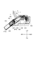
図2は、本実施形態のノズルユニットを例示する斜視模式図である。
なお、図2(a)は、洗浄ノズルがケーシングに収納された状態を表す斜視模式図であり、図2(b)は、洗浄ノズルが進出した状態を表す斜視模式図である。
FIG. 2 is a schematic perspective view illustrating the nozzle unit of this embodiment.
2A is a schematic perspective view showing a state in which the cleaning nozzle is housed in the casing, and FIG. 2B is a schematic perspective view showing a state in which the cleaning nozzle has advanced.
本実施形態のノズルユニット470は、図2に表したように、基台475と、基台475に支持された洗浄ノズル473と、洗浄ノズル473を移動させるノズルモータ476と、を有する。なお、図2に表した洗浄ノズル473は、単段式すなわち1本の可動部を有する洗浄ノズルであるが、本発明はこれだけに限定されるわけではない。洗浄ノズルは、複数の可動部を有する多段式の洗浄ノズルであってもよい。
As shown in FIG. 2, the
洗浄ノズル473は、ノズルモータ476から伝達される駆動力により、基台475に対して摺動自在に設けられている。ノズルモータ476は、基台475に固定されている。
The cleaning
また、洗浄ノズル473は、スライダ477を有する。スライダ477は、基台475に対して摺動自在に設けられている。そのため、洗浄ノズル473は、スライダ477とともに基台475に対して摺動可能である。これにより、洗浄ノズル473は、ケーシング400および基台475から進退自在に移動できる。
Further, the cleaning
ケーシング400は、ケースプレート401と、ケースカバー402と、を有する。ケースカバー402の前側には、ケースカバー402の開口部を開閉するシャッター420が設けられている。図2(b)に表したように、シャッター420は、洗浄ノズル473の進退に伴って開閉することができる。より具体的には、シャッター420は、ケースカバー402に対して回動自在に軸支されている。そして、シャッター420は、洗浄ノズル473がケーシング400から進出する際に、上部を中心として回動しケースカバー402の開口部を開けることができる。一方、シャッター420は、洗浄ノズル473がケーシング400へ後退する際あるいは後退した後に、上部を中心として回動しケースカバー402の開口部を閉じることができる。なお、シャッター420の設置形態は、これだけに限定されず、例えばケースプレート401に回動自在に軸支されていてもよい。
The
ケーシング400には、洗浄ノズル473の移動を案内する軌道ガイド450が設けられている。洗浄ノズル473は、軌道ガイド450により一定の軌道を描き、収納状態から進出状態へ変化する。このとき、洗浄ノズル473は、例えば便器800の上面などの水平面850(図4(a)参照)に対する洗浄ノズル473の軸473cの角度θ(図4(a)参照)が大きくなる姿勢へ遷移しつつ進出する。言い換えれば、洗浄ノズル473は、収納状態よりも起立する姿勢へ遷移しつつ進出する。これについて、図面を参照しつつ詳細に説明する。
The
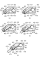
図3は、本実施形態の洗浄ノズルの軌道を例示する平面模式図である。
また、図4は、本実施形態のノズルユニットを右側方から眺めた平面模式図である。
FIG. 3 is a schematic plan view illustrating the trajectory of the cleaning nozzle of this embodiment.
FIG. 4 is a schematic plan view of the nozzle unit of this embodiment as viewed from the right side.
洗浄ノズル473には、ケーブルラック478(図6〜図14参照)が固定されている。ケーブルラック478は、例えば柔軟性を有する樹脂などの材料により形成されている。ケーブルラック478の少なくとも一側面には、歯車481、483(図6〜図14参照)と係合する凹凸が設けられている。そして、ケーブルラック478は、基台475に設けられた第1のケーブルガイド部479と、ケーシング400に設けられた第2のケーブルガイド部411と、に沿って衛生洗浄装置100内で摺動可能に支持されている。
A cable rack 478 (see FIGS. 6 to 14) is fixed to the
ノズルモータ476は、駆動出力を適宜減速させて歯車481、483に出力可能である。ケーブルラック478は、歯車483に係合され、歯車483の回転駆動力を直線方向の駆動力に変換して洗浄ノズル473を移動させる。つまり、洗浄ノズル473は、歯車481、483およびケーブルラック478を介してノズルモータ476から伝達される駆動力により、基台475に対して摺動自在に設けられている。
The
軌道ガイド450には、図3および図4に表したように、洗浄ノズル473の軌道を規制する軌道溝451が形成されている。一方、スライダ477には、図3および図4に表したように、軌道溝451に嵌合可能な嵌合部477bが設けられている。嵌合部477bは、軌道溝451に嵌合されている。そして、洗浄ノズル473が収納状態から進出状態へ変化する際には、スライダ477の嵌合部477bは、軌道溝451を摺動しつつ移動する。そのため、スライダ477は、軌道溝451と略同一の軌道を描き移動する。
As shown in FIGS. 3 and 4, the
嵌合部477bは、例えば回動不能な突起部としてスライダ477に付設されていてもよいし、スライダ477に対して回動自在な部分を有していてもよい。嵌合部477bがスライダ477に対して回動自在な部分を有する場合には、スライダ477の嵌合部477bは、軌道溝451を回動しつつ移動する。そのため、本願明細書において「摺動」という範囲には、接触状態で摺り動く場合だけではなく、接触状態で転がり動く場合が含まれるものとする。
The
軌道ガイド450は、曲線規制部453と、直線規制部455と、を有する。曲線規制部453は、略水平方向に形成されている。一方、直線規制部455は、曲線規制部453と接続された側の一端部が曲線規制部453と接続されていない側の他端部よりも高くなるように傾斜して形成されている。言い換えれば、直線規制部455は、曲線規制部453と接続されていない側の他端部が曲線規制部453と接続された側の一端部よりも低くなるように傾斜して形成されている。なお、直線規制部455にロック機構を持たせたり、角度変更用の駆動源を設けてもよい。
The
まず、洗浄ノズル473が収納状態から進出状態へ変化を始めると、スライダ477の嵌合部477bは、曲線規制部453を摺動する。このとき、洗浄ノズル473は、回動軸463によりケーシング400に対して回動自在に軸支された筒体461を通過する。筒体461は、筒状に形成され、洗浄ノズル473の角度に応じて回動軸463を中心として回動できる。つまり、筒体461のケーシング400に対する角度は、洗浄ノズル473の角度変化に連動して変化する。そして、筒体461および回動軸463は、洗浄ノズル473の移動を案内し規制することができる。
First, when the cleaning
そのため、洗浄ノズル473が収納状態から進出状態へ変化を始めると、嵌合部477bは、曲線規制部453に案内され略水平方向に移動する。一方で、洗浄ノズル473は、回動軸463を中心として回動する筒体461の内部を通過する。これにより、洗浄ノズル473は、洗浄ノズル473の軸473cの水平面850に対する角度θが大きくなる姿勢へ遷移しつつ進出する。言い換えれば、洗浄ノズル473は、収納状態よりも起立する姿勢へ遷移しつつ進出する。そのため、スライダ477の嵌合部477bが曲線規制部453を摺動する際には、洗浄ノズル473の先端部473aは、図3に表したように、曲線軌道491を描きつつ進出する。
Therefore, when the cleaning
続いて、スライダ477の嵌合部477bは、直線規制部455を摺動する。このとき、筒体461は、ケーシング400に対して回動自在に軸支されているため、直線規制部455の傾斜角度すなわちスライダ477および洗浄ノズル473の移動方向と、筒体461の軸方向と、は略同一となる。これにより、スライダ477の嵌合部477bが直線規制部455を摺動する際には、洗浄ノズル473の先端部473aは、図3に表したように、直線軌道493を描きつつ進出する。
Subsequently, the
本実施形態では、洗浄ノズル473の先端部473aが描く曲線軌道491は、洗浄ノズル473が便座200に着座した使用者の臀部と接触することを回避する軌道である。一方、洗浄ノズル473の先端部473aが描く直線軌道493は、進出状態へ到達する軌道である。そのため、進出状態の洗浄ノズル473の軸473cは、便座200に着座した使用者の臀部とは干渉しない。また、進出状態および進出途中の洗浄ノズル473は、便座200に着座した使用者の臀部とは接触しない。これにより、収納状態の洗浄ノズル473の軸473cが便座200に着座した使用者の臀部と干渉する程度にまで、洗浄ノズル473の軸473cの水平面850に対する角度θが小さい姿勢で洗浄ノズル473を収納させることができる。
In the present embodiment, the
なお、洗浄ノズル473と使用者の臀部との干渉を回避する角度θは、一般的な形状を有する便座200および便器800、並びに一般的な収納位置(例えば臀部との水平方向および鉛直方向の相対的位置)に設置された洗浄ノズル473を有する衛生洗浄装置100を使用した場合には、例えば約30°〜45°程度である。
Note that the angle θ for avoiding the interference between the cleaning
本実施形態によれば、図3および図4(a)〜図4(e)に表したように、洗浄ノズル473は、洗浄ノズル473の軸473cの水平面850に対する角度θが大きくなる姿勢へ遷移しつつ進出する。また、収納状態の洗浄ノズル473の高さをより低く抑えた場合でも、進出状態および進出途中の洗浄ノズル473が便座200に着座した使用者の臀部と接触することを回避できる。さらに、洗浄ノズル473の軸473cの水平面850に対する角度θを変化させるために必要な回動スペースを最小限にすることができる。これにより、収納状態の洗浄ノズル473の高さをより低く抑えることができる。そのため、衛生洗浄装置100の高さをより低く抑え、衛生洗浄装置100のコンパクト化を図ることができる。
According to the present embodiment, as shown in FIGS. 3 and 4A to 4E, the cleaning
本実施形態にかかる衛生洗浄装置100は、洗浄ノズル473を洗浄あるいは清掃するノズル洗浄部を備える。ノズル洗浄部は、洗浄ノズル473が収納状態から進出状態へ変化しているときに、洗浄ノズル473の外観面(側面あるいは胴体面)に対して吐水部から洗浄水を吐水し、洗浄ノズル473の外観面を洗浄することができる。あるいは、ノズル洗浄部は、洗浄ノズル473が進出状態から収納状態へ変化しているときに、洗浄ノズル473の外観面に対して洗浄水を吐水し、洗浄ノズル473の外観面を洗浄することができる。あるいは、ノズル洗浄部は、洗浄ノズル473が収納状態から進出状態へ変化しているときに、および洗浄ノズル473が進出状態から収納状態へ変化しているときに、洗浄ノズル473の外観面に対して洗浄水を吐水し、洗浄ノズル473の外観面を洗浄することができる。
The
前述したように、洗浄ノズル473は、洗浄ノズル473の軸473cの水平面850に対する角度θが大きくなる姿勢へ遷移しつつ進出する。つまり、洗浄ノズル473は、角度変化を伴ってケーシング400から進出したり、ケーシング400へ後退する。そのため、ノズル洗浄部が単に洗浄水を吐水すると、ノズル洗浄部の吐水部と洗浄ノズル473の外観面との間の距離が変化する。そのため、洗浄ノズル473の外観面に洗浄むらや洗い残しが生じ、洗浄ノズル473を衛生的に保てないおそれがある。また、ノズル洗浄部の吐水部と洗浄ノズル473の外観面との間の距離が変化することで洗浄ノズル473の外観面への洗浄水の当たり方が変化するため、洗浄水の飛び散る範囲や方向が洗浄ノズル473の状態によって大きく変わる。そのため、飛び散り対策を行うことを考えると大がかりな構造が必要となる。
As described above, the cleaning
これに対して、本実施形態にかかる衛生洗浄装置100では、例えば図3に表した矢印Aのように、ノズル洗浄部の吐水部と洗浄ノズル473の外観面との間の距離Lは、洗浄ノズル473が収納状態から進出状態へ変化しているとき及び進出状態から収納状態へ変化しているときにおいて一定である。なお、図3に表した矢印Aは、説明の便宜上のものであり、ノズル洗浄部の吐水部が図3に表した矢印Aの一端(洗浄ノズル473の外観面とは反対側の一端)のような軌跡を描きつつ変化することを意味するものではない。
On the other hand, in the
これによれば、洗浄ノズル473が角度変化を伴って進退しても、洗浄ノズル473の外観面に対して一定の距離で洗浄水がノズル洗浄部から吐水される。そのため、洗浄ノズル473の外観面における洗浄位置の違いにより洗いむらや洗い残しが発生することを抑え、洗浄ノズル473の外観面を衛生的に保つことができる。また、洗浄ノズル473の外観面への洗浄水の当たり方が一定であるため、洗浄水の飛び散る範囲や方向が洗浄ノズル473の状態によっては変わらない。そのため、飛び散り対策を行うことを考えると簡単な構造で対策が可能となる。
According to this, even if the
また、本実施形態のノズル洗浄部は、洗浄ノズル473の先端部473aが曲線軌道491の後半以降に進出すると洗浄水の吐水を開始する。そのため、ノズル洗浄部の吐水部と洗浄ノズル473の外観面との間の距離Lをより大きく調整する必要はない。これにより、ノズル洗浄部の吐水部と洗浄ノズル473の外観面との間の距離Lを一定の距離でより安定させて洗浄水をノズル洗浄部から吐水させることができる。また、例えば、ノズル洗浄部は、洗浄ノズル473の先端部473aが直線軌道493に進出すると洗浄水の吐水を開始する。洗浄ノズル473の先端部473aが直線軌道493を描く際には、洗浄ノズル473は角度変化を伴わずに進出する。そのため、洗浄ノズル473の先端部473aが直線軌道493を描いているときには、ノズル洗浄部の吐水部と洗浄ノズル473の外観面との間の距離Lを調整する必要はない。これにより、ノズル洗浄部の吐水部と洗浄ノズル473の外観面との間の距離Lを一定の距離でさらに安定させて洗浄水をノズル洗浄部から吐水させることができる。
In addition, the nozzle cleaning unit of the present embodiment starts to discharge the cleaning water when the
次に、ノズル洗浄部の具体例について、図面を参照しつつ説明する。
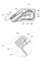
図5は、本実施形態のノズル洗浄部の具体例を表す斜視模式図である。
また、図6〜図9は、本具体例のノズル洗浄部の動作を説明するための断面模式図である。
なお、図6〜図9は、洗浄ノズル473の軸473cに沿うような切断面すなわち図2(a)に表した切断面A−Aにおける断面模式図である。
また、図7(b)は、図7(a)に表した領域Bの拡大模式図であり、図8(b)は、図8(a)に表した領域Cの拡大模式図である。
また、図5においては、説明の便宜上、軌道ガイド450や筒体461などを省略している。
Next, a specific example of the nozzle cleaning unit will be described with reference to the drawings.
FIG. 5 is a schematic perspective view illustrating a specific example of the nozzle cleaning unit of the present embodiment.
6 to 9 are schematic cross-sectional views for explaining the operation of the nozzle cleaning unit of this example.
6 to 9 are schematic cross-sectional views taken along a cutting plane AA shown in FIG. 2A, that is, a cutting plane along the
Moreover, FIG.7 (b) is an expansion schematic diagram of the area | region B represented to Fig.7 (a), FIG.8 (b) is an expansion schematic diagram of the area | region C represented to Fig.8 (a).
Further, in FIG. 5, the
図5に表したように、本具体例のノズル洗浄部510は、シャッター(連動部材)420に設けられている。図2に関して前述したように、シャッター420は、洗浄ノズル473の収納状態から進出状態への変化および進出状態から収納状態への変化に連動できる。ノズル洗浄部510は、洗浄ノズル473の外観面に対して洗浄水を吐水する吐水部515と、吐水部515と洗浄ノズル473の外観面とを一定に保つリブ(距離規制部材)511と、を有する。なお、距離規制部材は、シャッター420およびノズル洗浄部510の少なくともいずれかに設けられていてもよい。
As shown in FIG. 5, the
図6(a)に表したように、洗浄ノズル473がケーシング400に収納された状態において、シャッター420は、ケースカバー402の開口部を閉じている。このとき、ノズル洗浄部510のリブ511と、洗浄ノズル473の外観面と、は接触していない。続いて、図6(b)に表したように、洗浄ノズル473は、収納状態から進出状態へ変化を始めるとシャッター420と接触しシャッター420を押す。そうすると、シャッター420は、洗浄ノズル473の進退変化に連動し上部を中心として回動する。このときにも、ノズル洗浄部510のリブ511と、洗浄ノズル473の外観面と、は接触していない。
As illustrated in FIG. 6A, the
続いて、図7(a)に表したように、洗浄ノズル473がさらに進出すると、シャッター420はさらに回動する。そして、図7(b)に表したように、ノズル洗浄部510のリブ511は、洗浄ノズル473の外観面と接触する。リブ511が洗浄ノズル473の外観面と接触した状態において、ノズル洗浄部510は、吐水部515から洗浄水を吐水し、洗浄ノズル473の外観面を洗浄することができる。
Subsequently, as shown in FIG. 7A, when the cleaning
続いて、図8(a)に表したように、洗浄ノズル473は、さらに進出する。このとき、リブ511と洗浄ノズル473の外観面とは、接触している。つまり、洗浄ノズル473は、リブ511と洗浄ノズル473の外観面とが接触した状態で進出する。そのため、図7(b)および図8(b)に表したように、ノズル洗浄部510の吐水部515と洗浄ノズル473の外観面との間の距離Lは、洗浄ノズル473が収納状態から進出状態へ変化しているときにおいて一定である。
Subsequently, as illustrated in FIG. 8A, the cleaning
続いて、図9に表したように、洗浄ノズル473は、リブ511と洗浄ノズル473の外観面とが接触した状態で所定の洗浄位置まで進出する。このときにも、ノズル洗浄部510の吐水部515と洗浄ノズル473の外観面との間の距離Lは一定である。そして、洗浄ノズル473は、吐水口474から水を噴射して、便座200に座った使用者の「おしり」などを洗浄することができる。
Subsequently, as illustrated in FIG. 9, the cleaning
本具体例によれば、洗浄ノズル473が角度変化を伴って進退しても、洗浄ノズル473の外観面に対して一定の距離で洗浄水がノズル洗浄部510から吐水される。そのため、洗浄ノズル473の外観面における洗浄位置の違いにより洗いむらや洗い残しが発生することを抑え、洗浄ノズル473の外観面を衛生的に保つことができる。また、洗浄ノズル473の外観面への洗浄水の当たり方が一定であるため、洗浄水の飛び散る範囲や方向が洗浄ノズル473の状態によって変わらない。そのため、飛び散り対策を行うことを考えると簡単な構造で対策が可能となる。
According to this specific example, even if the
また、本具体例のノズル洗浄部510は、洗浄ノズル473の進退変化に連動するシャッター420に設けられている。そのため、ノズル洗浄部510を別個に形成し、洗浄ノズル473の進退変化に連動させる必要はない。具体的には、例えば、洗浄ノズル473の進退変化にノズル洗浄部510を連動させるモータや歯車などを設ける必要はない。そのため、衛生洗浄装置100のコンパクト化を図ることができる。
In addition, the
また、本具体例のノズル洗浄部510は、吐水部515と洗浄ノズル473の外観面とを一定に保つリブ511を有する。そのため、図示しない制御部により吐水部515の位置を制御する必要はない。言い換えれば、ノズル洗浄部510の自重を利用することにより、ノズル洗浄部510の吐水部515と洗浄ノズル473の外観面との間の距離Lを一定に保つことができる。これにより、より簡易的な構造で、ノズル洗浄部510の吐水部515と洗浄ノズル473の外観面との間の距離Lを一定に保つことができる。
In addition, the
また、本具体例のノズル洗浄部510は、収納状態の洗浄ノズル473よりも前方に配置されたシャッター420に設けられているため、洗浄ノズル473の中央部の外観面だけではなく先端部の外観面を洗浄することができる。これにより、洗浄ノズル473をケーシング400の奥の方(後方)に収納する必要はなく、衛生洗浄装置100の前後方向のコンパクト化を図ることができる。
In addition, since the
図10〜図14は、本実施形態のノズル洗浄部の他の具体例を表す断面模式図である。 なお、図10〜図14は、洗浄ノズル473の軸473cに沿うような切断面すなわち図2(a)に表した切断面A−Aにおける断面模式図である。
また、図10(b)は、図10(a)に表した領域Dの拡大模式図である。図11(b)は、図11(a)に表した領域Eの拡大模式図である。図13(b)は、図13(a)に表した領域Fの拡大模式図である。図14(b)は、図14(a)に表した領域Gの拡大模式図である。
FIGS. 10-14 is a cross-sectional schematic diagram showing the other specific example of the nozzle washing | cleaning part of this embodiment. 10 to 14 are schematic cross-sectional views along a cut surface along the
FIG. 10B is an enlarged schematic diagram of the region D shown in FIG. FIG. 11B is an enlarged schematic diagram of the region E illustrated in FIG. FIG. 13B is an enlarged schematic diagram of the region F illustrated in FIG. FIG. 14B is an enlarged schematic diagram of the region G shown in FIG.
本具体例のノズル洗浄部520は、図5〜図9に関して前述した具体例のノズル洗浄部510と同様に、シャッター420に設けられている。また、本具体例のノズル洗浄部520は、洗浄ノズル473の外観面に対して洗浄水を吐水する吐水部525と、吐水部525と洗浄ノズル473の外観面とを一定に保つリブ521と、を有する。
The
本具体例の洗浄ノズル473は、ノズルヘッド471と、シリンダ472と、を有する。すなわち、本具体例の洗浄ノズル473は、2段式である。ノズルヘッド471は、シリンダ472に対して摺動自在に設けられ、少なくともその一部がシリンダ472の中に格納可能とされている。ノズルヘッド471は、ノズルモータ476(図2参照)から伝達される駆動力により、基台475に対して摺動自在に設けられている。
The cleaning
より具体的に説明すると、ノズルヘッド471には、ケーブルラック478が固定されている。ノズルモータ476は、駆動出力を適宜減速させて歯車481、483に出力可能である。ケーブルラック478は、歯車483に係合され、歯車483の回転駆動力を直線方向の駆動力に変換してノズルヘッド471を移動させる。つまり、ノズルヘッド471は、歯車481、483およびケーブルラック478を介してノズルモータ476から伝達される駆動力により、基台475に対して摺動自在に設けられている。
More specifically, a
ノズルヘッド471およびシリンダ472の進出順序は、例えば以下の如くである。図10(a)および図10(b)に表したように、ノズルヘッド471がシリンダ472の中に格納された状態で、洗浄ノズル473の先端部473aが曲線軌道491を描きつつ進出する。その後、図11(a)および図11(b)ならびに図12に表したように、ノズルヘッド471がシリンダ472の中から外へ摺動し、洗浄ノズル473の先端部473aが直線軌道493を描きつつ進出する。その後、図13(a)および図13(b)ならびに図14に表したように、シリンダ472がノズルヘッド471に引っ張られることにより、洗浄ノズル473の先端部473aが直線軌道493を描きつつさらに進出する。
The advancement order of the
洗浄ノズル473がケーシング400に収納された状態、および洗浄ノズル473が収納状態から進出状態へ変化を始めた直後の状態は、図6(a)および図6(b)に表した状態と同様である。
続いて、ノズルヘッド471がシリンダ472の中から外へ摺動すると、シャッター420はさらに回動する。そして、図10(a)および図10(b)に表したように、ノズル洗浄部520のリブ521は、ノズルヘッド471の外観面と接触する。リブ521がノズルヘッド471の外観面と接触した状態において、ノズル洗浄部520は、吐水部525から洗浄水を吐水し、ノズルヘッド471の外観面を洗浄することができる。
The state in which the
Subsequently, when the
続いて、図11(a)および図11(b)に表したように、ノズルヘッド471は、シリンダ472の中から外へさらに摺動する。このとき、リブ521とノズルヘッド471の外観面とは、接触している。つまり、ノズルヘッド471は、リブ521とノズルヘッド471の外観面とが接触した状態で、シリンダ472の中から外へ摺動する。そのため、図10(b)および図11(b)に表したように、ノズル洗浄部520の吐水部525とノズルヘッド471の外観面との間の距離Lは、ノズルヘッド471がシリンダ472の中から外へ摺動するときにおいて一定である。
Subsequently, as shown in FIGS. 11A and 11B, the
続いて、図12に表したように、ノズルヘッド471は、リブ521とノズルヘッド471の外観面とが接触した状態で所定位置まで進出する。このときにも、ノズル洗浄部520の吐水部525とノズルヘッド471の外観面との間の距離Lは一定である。
Subsequently, as illustrated in FIG. 12, the
続いて、図13(a)に表したように、シリンダ472がノズルヘッド471に引っ張られることにより、洗浄ノズル473の先端部473aが直線軌道493を描きつつさらに進出する。このとき、図13(b)に表したように、ノズル洗浄部520のリブ521は、ノズルヘッド471の外観面からシリンダ472の外観面へ乗り上げる。そして、ノズル洗浄部520のリブ521は、シリンダ472の外観面と接触する。リブ521がシリンダ472の外観面と接触した状態において、ノズル洗浄部520は、吐水部525から洗浄水を吐水し、シリンダ472の外観面を洗浄することができる。
Subsequently, as illustrated in FIG. 13A, when the
図14(a)および図14(b)に表したように、シリンダ472は、ノズルヘッド471に引っ張られさらに進出する。このとき、リブ521とシリンダ472の外観面とは、接触している。つまり、シリンダ472は、リブ521とシリンダ472の外観面とが接触した状態で進出する。そのため、図13(b)および図14(b)に表したように、ノズル洗浄部520の吐水部525とシリンダ472の外観面との間の距離Lは、シリンダ472がノズルヘッド471に引っ張られ進出するときにおいて一定である。
As shown in FIG. 14A and FIG. 14B, the
続いて、シリンダ472は、リブ521とシリンダ472の外観面とが接触した状態で所定の洗浄位置まで進出する。このときにも、ノズル洗浄部520の吐水部525とシリンダ472の外観面との間の距離Lは一定である。そして、洗浄ノズル473は、吐水口474から水を噴射して、便座200に座った使用者の「おしり」などを洗浄することができる。
Subsequently, the
本具体例によれば、多段式の洗浄ノズル473の進退変化の際に段差が存在する場合でも、ノズル洗浄部520の吐水部525と、ノズルヘッド471およびシリンダ472の外観面と、の間の距離Lを一定に保つことができる。そのため、多段式の洗浄ノズル473が角度変化を伴って進退しても、洗浄ノズル473の外観面に対して一定の距離で洗浄水がノズル洗浄部520から吐水される。そのため、多段式の洗浄ノズル473の外観面における洗浄位置の違いにより洗いむらや洗い残しが発生することを抑え、多段式の洗浄ノズル473の外観面を衛生的に保つことができる。また、多段式の洗浄ノズル473の外観面への洗浄水の当たり方が一定であるため、洗浄水の飛び散る範囲や方向が洗浄ノズル473の状態によって変わらない。そのため、飛び散り対策を行うことを考えると簡単な構造で対策が可能となる。また、その他の効果についても、図5〜図9に関して前述した具体例の効果と同様の効果が得られる。
According to this specific example, even when there is a step when the
以上説明したように、本実施形態によれば、ノズル洗浄部510、520の吐水部515、525と洗浄ノズル473の外観面との間の距離Lは、洗浄ノズル473が収納状態から進出状態へ変化しているとき及び進出状態から収納状態へ変化しているときにおいて一定である。そのため、洗浄ノズル473が角度変化を伴って進退しても、洗浄ノズル473の外観面に対して一定の距離で洗浄水がノズル洗浄部510、520から吐水される。そのため、洗浄ノズル473の外観面における洗浄位置の違いにより洗いむらや洗い残しが発生することを抑え、洗浄ノズル473の外観面を衛生的に保つことができる。また、洗浄ノズル473の外観面への洗浄水の当たり方が一定であるため、洗浄水の飛び散る範囲や方向が洗浄ノズル473の状態によって変わらない。そのため、飛び散り対策を行うことを考えると簡単な構造で対策が可能となる。
As described above, according to the present embodiment, the distance L between the
以上、本発明の実施の形態について説明した。しかし、本発明はこれらの記述に限定されるものではない。前述の実施の形態に関して、当業者が適宜設計変更を加えたものも、本発明の特徴を備えている限り、本発明の範囲に包含される。例えば、ノズル洗浄部510、520などが備える各要素の形状、寸法、材質、配置などや吐水部515、525の設置形態などは、例示したものに限定されるわけではなく適宜変更することができる。
また、前述した各実施の形態が備える各要素は、技術的に可能な限りにおいて組み合わせることができ、これらを組み合わせたものも本発明の特徴を含む限り本発明の範囲に包含される。
The embodiment of the present invention has been described above. However, the present invention is not limited to these descriptions. As long as the features of the present invention are provided, those skilled in the art appropriately modified the design of the above-described embodiments are also included in the scope of the present invention. For example, the shape, size, material, arrangement, and the like of each element included in the
Moreover, each element with which each embodiment mentioned above is provided can be combined as long as technically possible, and the combination of these is also included in the scope of the present invention as long as it includes the features of the present invention.
100 衛生洗浄装置、 200 便座、 300 便蓋、 400 ケーシング、 401 ケースプレート、 402 ケースカバー、 404 着座検知センサ、 411 第2のケーブルガイド部、 420 シャッター、 450 軌道ガイド、 451 軌道溝、 453 曲線規制部、 455 直線規制部、 461 筒体、 463 回動軸、 470 ノズルユニット、 471 ノズルヘッド、 472 シリンダ、 473 洗浄ノズル、 473a 先端部、 473c 軸、 474 吐水口、 475 基台、 476 ノズルモータ、 477 スライダ、 477b 嵌合部、 478 ケーブルラック、 479 第1のケーブルガイド部、 481 歯車、 483 歯車、 491 曲線軌道、 493 直線軌道、 510 ノズル洗浄部、 511 リブ、 515 吐水部、 520 ノズル洗浄部、 521 リブ、 525 吐水部、 800 便器、 801 ボウル、 850 水平面 100 sanitary washing device, 200 toilet seat, 300 toilet lid, 400 casing, 401 case plate, 402 case cover, 404 seating detection sensor, 411 second cable guide, 420 shutter, 450 track guide, 451 track groove, 453 curve regulation Part, 455 linear restriction part, 461 cylinder, 463 rotation shaft, 470 nozzle unit, 471 nozzle head, 472 cylinder, 473 cleaning nozzle, 473a tip, 473c shaft, 474 water outlet, 475 base, 476 nozzle motor, 477 slider, 477b fitting portion, 478 cable rack, 479 first cable guide portion, 481 gear, 483 gear, 491 curved track, 493 linear track, 510 nozzle cleaning unit, 511 rib, 515 discharge Water section, 520 nozzle cleaning section, 521 rib, 525 water discharge section, 800 toilet bowl, 801 bowl, 850 horizontal plane
Claims (8)
前記洗浄ノズルを収納可能なケーシングと、
吐水部を有し、前記吐水部から洗浄水を吐水して前記洗浄ノズルを洗浄するノズル洗浄部と、
を備え、
前記洗浄ノズルは、前記洗浄ノズルの軸の水平面に対する角度が大きくなる姿勢へ遷移しつつ前記ケーシングに収納された収納状態から前記身体を洗浄する進出状態へ進出変化、及び、前記洗浄ノズルの軸の水平面に対する角度が小さくなる姿勢へ遷移しつつ前記進出状態から前記収納状態へ収納変化し、
前記ノズル洗浄部は、前記洗浄ノズルの前記進出変化中および前記収納変化中の少なくともいずれかにおいて前記洗浄ノズルの胴体面に向けて洗浄水を吐水し、
前記吐水部と前記胴体面との間の距離は、前記洗浄ノズルの前記進出変化中および前記収納変化中において一定であることを特徴とする衛生洗浄装置。 A cleaning nozzle that has a water discharge port and sprays water from the water discharge port to clean the user's body;
A casing capable of storing the washing nozzle;
A nozzle cleaning unit that has a water discharge unit, and discharges cleaning water from the water discharge unit to clean the cleaning nozzle;
With
The cleaning nozzle changes from a stored state stored in the casing to an advanced state in which the body is cleaned while transitioning to a posture in which the angle of the axis of the cleaning nozzle with respect to a horizontal plane increases, and the shaft of the cleaning nozzle While changing to a posture in which the angle with respect to the horizontal plane becomes small, the storage changes from the advanced state to the storage state,
The nozzle cleaning unit spouts cleaning water toward the body surface of the cleaning nozzle during at least one of the advancement change and the storage change of the cleaning nozzle,
The sanitary washing apparatus according to claim 1, wherein a distance between the water discharge unit and the body surface is constant during the advancement change and the storage change of the washing nozzle.
前記リブは、前記洗浄ノズルの前記進出変化中および前記収納変化中において前記洗浄ノズルの胴体面と接触することを特徴とする請求項3記載の衛生洗浄装置。 The distance regulating member is a rib provided on at least one of the interlocking member and the nozzle cleaning unit,
4. The sanitary washing device according to claim 3, wherein the rib contacts the body surface of the washing nozzle during the advancement change and the storage change of the washing nozzle.
前記ノズル洗浄部は、前記シャッターに設けられたことを特徴とする請求項1〜4のいずれか1つに記載の衛生洗浄装置。 A shutter that is provided on the front side of the casing and opens and closes in conjunction with the advancement change and the storage change of the cleaning nozzle;
The said nozzle washing | cleaning part was provided in the said shutter, The sanitary washing apparatus as described in any one of Claims 1-4 characterized by the above-mentioned.
前記洗浄ノズルが前記使用者の臀部と接触することを回避する曲線軌道と、
前記洗浄ノズルが前記進出状態へ到達する直線軌道と、
を有し、
前記ノズル洗浄部は、前記先端部が前記曲線軌道の後半以降に進出すると前記洗浄水の吐水を開始することを特徴とする請求項1〜5のいずれか1つに記載の衛生洗浄装置。 The trajectory drawn by the tip of the washing nozzle is
A curved trajectory that avoids contact of the cleaning nozzle with the buttocks of the user;
A linear trajectory for the cleaning nozzle to reach the advanced state;
Have
The sanitary washing device according to any one of claims 1 to 5, wherein the nozzle washing unit starts discharging the washing water when the tip part advances after the second half of the curved track.
Priority Applications (1)
| Application Number | Priority Date | Filing Date | Title |
|---|---|---|---|
| JP2011017172A JP5201224B2 (en) | 2011-01-28 | 2011-01-28 | Sanitary washing device |
Applications Claiming Priority (1)
| Application Number | Priority Date | Filing Date | Title |
|---|---|---|---|
| JP2011017172A JP5201224B2 (en) | 2011-01-28 | 2011-01-28 | Sanitary washing device |
Publications (2)
| Publication Number | Publication Date |
|---|---|
| JP2012158865A JP2012158865A (en) | 2012-08-23 |
| JP5201224B2 true JP5201224B2 (en) | 2013-06-05 |
Family
ID=46839627
Family Applications (1)
| Application Number | Title | Priority Date | Filing Date |
|---|---|---|---|
| JP2011017172A Active JP5201224B2 (en) | 2011-01-28 | 2011-01-28 | Sanitary washing device |
Country Status (1)
| Country | Link |
|---|---|
| JP (1) | JP5201224B2 (en) |
Families Citing this family (1)
| Publication number | Priority date | Publication date | Assignee | Title |
|---|---|---|---|---|
| JP6946975B2 (en) * | 2017-11-27 | 2021-10-13 | 株式会社アイシン | Washing toilet seat device |
Family Cites Families (4)
| Publication number | Priority date | Publication date | Assignee | Title |
|---|---|---|---|---|
| JPS6429532A (en) * | 1987-07-22 | 1989-01-31 | Toto Ltd | Sanitary washer |
| JP2001059253A (en) * | 1998-04-08 | 2001-03-06 | Toto Ltd | Human-body washing device |
| JP2008214956A (en) * | 2007-03-05 | 2008-09-18 | Matsushita Electric Ind Co Ltd | Nozzle device and sanitary washing unit using it |
| CN102076918B (en) * | 2008-07-03 | 2012-12-26 | 松下电器产业株式会社 | Sanitary cleaning device |
-
2011
- 2011-01-28 JP JP2011017172A patent/JP5201224B2/en active Active
Also Published As
| Publication number | Publication date |
|---|---|
| JP2012158865A (en) | 2012-08-23 |
Similar Documents
| Publication | Publication Date | Title |
|---|---|---|
| JP5429254B2 (en) | Sanitary washing device | |
| KR101294110B1 (en) | Sanitary washing apparatus | |
| JP5598637B1 (en) | Nozzle device and sanitary washing device using it | |
| JP5999418B2 (en) | Local cleaning equipment | |
| JP5565707B2 (en) | Sanitary washing device | |
| JP5246277B2 (en) | Sanitary washing device | |
| JP5201224B2 (en) | Sanitary washing device | |
| JP2007247281A (en) | Warm water washing device | |
| JP5633803B2 (en) | Sanitary washing device | |
| JP4940748B2 (en) | Nozzle device and sanitary washing device using it | |
| JP5732876B2 (en) | Sanitary washing device | |
| JP5626304B2 (en) | Nozzle device and sanitary washing device using it | |
| JP5605579B2 (en) | Sanitary washing device | |
| JP6515464B2 (en) | Human body part cleaning device | |
| JP6387520B2 (en) | Nozzle device and sanitary washing device using it | |
| JP5761658B2 (en) | Sanitary washing device | |
| JP4974065B2 (en) | Sanitary washing device | |
| JP6819937B2 (en) | Nozzle unit and sanitary cleaning equipment | |
| JP5338020B2 (en) | Nozzle device and sanitary washing device using it | |
| JP5093030B2 (en) | Nozzle device and sanitary washing device using it | |
| TWI473928B (en) | Sanitary cleaning device | |
| JP5828214B2 (en) | Sanitary washing device | |
| JP6848557B2 (en) | Sanitary washing toilet seat device | |
| JP5884587B2 (en) | Toilet seat device | |
| JP6848556B2 (en) | Sanitary washing toilet seat device |
Legal Events
| Date | Code | Title | Description |
|---|---|---|---|
| A621 | Written request for application examination |
Free format text: JAPANESE INTERMEDIATE CODE: A621 Effective date: 20121127 |
|
| A871 | Explanation of circumstances concerning accelerated examination |
Free format text: JAPANESE INTERMEDIATE CODE: A871 Effective date: 20121127 |
|
| TRDD | Decision of grant or rejection written | ||
| A975 | Report on accelerated examination |
Free format text: JAPANESE INTERMEDIATE CODE: A971005 Effective date: 20130110 |
|
| A01 | Written decision to grant a patent or to grant a registration (utility model) |
Free format text: JAPANESE INTERMEDIATE CODE: A01 Effective date: 20130115 |
|
| A61 | First payment of annual fees (during grant procedure) |
Free format text: JAPANESE INTERMEDIATE CODE: A61 Effective date: 20130128 |
|
| R150 | Certificate of patent or registration of utility model |
Ref document number: 5201224 Country of ref document: JP Free format text: JAPANESE INTERMEDIATE CODE: R150 Free format text: JAPANESE INTERMEDIATE CODE: R150 |
|
| FPAY | Renewal fee payment (event date is renewal date of database) |
Free format text: PAYMENT UNTIL: 20160222 Year of fee payment: 3 |