JP5199186B2 - Mounting mechanism, especially for centrifuges that separate blood - Google Patents
Mounting mechanism, especially for centrifuges that separate blood Download PDFInfo
- Publication number
- JP5199186B2 JP5199186B2 JP2009138348A JP2009138348A JP5199186B2 JP 5199186 B2 JP5199186 B2 JP 5199186B2 JP 2009138348 A JP2009138348 A JP 2009138348A JP 2009138348 A JP2009138348 A JP 2009138348A JP 5199186 B2 JP5199186 B2 JP 5199186B2
- Authority
- JP
- Japan
- Prior art keywords
- chuck
- distal
- transmission body
- proximal
- channel
- Prior art date
- Legal status (The legal status is an assumption and is not a legal conclusion. Google has not performed a legal analysis and makes no representation as to the accuracy of the status listed.)
- Expired - Fee Related
Links
Images

Classifications
-
- B—PERFORMING OPERATIONS; TRANSPORTING
- B04—CENTRIFUGAL APPARATUS OR MACHINES FOR CARRYING-OUT PHYSICAL OR CHEMICAL PROCESSES
- B04B—CENTRIFUGES
- B04B7/00—Elements of centrifuges
- B04B7/02—Casings; Lids
- B04B7/06—Safety devices ; Regulating
-
- B—PERFORMING OPERATIONS; TRANSPORTING
- B04—CENTRIFUGAL APPARATUS OR MACHINES FOR CARRYING-OUT PHYSICAL OR CHEMICAL PROCESSES
- B04B—CENTRIFUGES
- B04B7/00—Elements of centrifuges
-
- B—PERFORMING OPERATIONS; TRANSPORTING
- B04—CENTRIFUGAL APPARATUS OR MACHINES FOR CARRYING-OUT PHYSICAL OR CHEMICAL PROCESSES
- B04B—CENTRIFUGES
- B04B15/00—Other accessories for centrifuges
-
- B—PERFORMING OPERATIONS; TRANSPORTING
- B23—MACHINE TOOLS; METAL-WORKING NOT OTHERWISE PROVIDED FOR
- B23B—TURNING; BORING
- B23B31/00—Chucks; Expansion mandrels; Adaptations thereof for remote control
- B23B31/02—Chucks
- B23B31/10—Chucks characterised by the retaining or gripping devices or their immediate operating means
- B23B31/12—Chucks with simultaneously-acting jaws, whether or not also individually adjustable
- B23B31/22—Jaws in the form of balls
-
- Y—GENERAL TAGGING OF NEW TECHNOLOGICAL DEVELOPMENTS; GENERAL TAGGING OF CROSS-SECTIONAL TECHNOLOGIES SPANNING OVER SEVERAL SECTIONS OF THE IPC; TECHNICAL SUBJECTS COVERED BY FORMER USPC CROSS-REFERENCE ART COLLECTIONS [XRACs] AND DIGESTS
- Y10—TECHNICAL SUBJECTS COVERED BY FORMER USPC
- Y10T—TECHNICAL SUBJECTS COVERED BY FORMER US CLASSIFICATION
- Y10T279/00—Chucks or sockets
- Y10T279/24—Chucks or sockets by centrifugal force
- Y10T279/247—Chucks or sockets by centrifugal force to grip tool or workpiece
Landscapes
- Engineering & Computer Science (AREA)
- Mechanical Engineering (AREA)
- Centrifugal Separators (AREA)
Description
本発明の分野
本明細書は、血液および類似の液体の成分を分離するための遠心分離機に関する。
FIELD OF THE INVENTION This specification relates to centrifuges for separating blood and similar liquid components.
1つの態様において、本明細書は、分離ボウルをメカニカルチャックに取り付けるためのメカニズム(機構)に関する。 In one aspect, the present description relates to a mechanism for attaching a separation bowl to a mechanical chuck.
関連技術の説明
従来の血液処理デバイスは、大きな遠心力を用いて、分離および収集することができる種々の血液成分の種々の密度に基づき、全血の種々の成分を分離する。
Description of Related Art Conventional blood processing devices use large centrifugal forces to separate different components of whole blood based on different densities of different blood components that can be separated and collected.
これらの血液処理デバイスは、全血を供給するボウル、ボウルを固定するチャックおよびチャックに接続可能な遠心分離モーターを有してよい。遠心分離モーターは、チャックおよびそこに固定するボウルを非常に高速で駆動させ、それによって、血液の種々の相の分離を可能にする。 These blood processing devices may have a bowl for supplying whole blood, a chuck for securing the bowl, and a centrifuge motor connectable to the chuck. Centrifugal motors drive the chuck and the bowl secured thereto at very high speed, thereby allowing the separation of various phases of blood.
これらのデバイスの設計における要素は、運転中のボウルのチャックからの望ましくない離脱、そして、その結果としてのボウル、チャックの損傷および血液製剤の損失を避けるために、分離ボウルのチャックへの確実な接続である。 The elements in the design of these devices are to ensure reliable separation of the separation bowl to the chuck to avoid undesired detachment of the bowl from operation and the resulting bowl, chuck damage and blood product loss. It is a connection.
分離ボウルをメカニカルチャックに固定するための種々のメカニズムが、ボウルをチャックから簡単に装着および離脱できるようにすると同時に、運転中、分離ボウルをチャックに堅固に固定するために、何年にもわたって開発されてきた。 Various mechanisms for securing the separation bowl to the mechanical chuck have made it possible for years to secure the separation bowl firmly to the chuck during operation while allowing the bowl to be easily mounted and removed from the chuck. Have been developed.
例えば、米国特許第5 658 231号は、チャックの周囲に沿って等間隔に並んだ複数のスロットを設けたチャックハウジングを有して成る遠心分離チャックを開示し、ハウジング内では把持フィンガーが収容されている。ピンによってチャックハウジングの外周に枢動可能に把持フィンガーを取り付け、把持フィンガーは遠心分離機の回転軸に略平行な軸方向で延在する。各把持フィンガーは先端部を含み、分離ボウルの基底部を受容するように構成され、それによって、ボウルをチャックに固定する。 For example, US Pat. No. 5,658,231 discloses a centrifuge chuck having a chuck housing with a plurality of slots spaced equidistantly around the circumference of the chuck, in which a gripping finger is received. ing. A gripping finger is pivotally attached to the outer periphery of the chuck housing by a pin, and the gripping finger extends in an axial direction substantially parallel to the rotation axis of the centrifuge. Each gripping finger includes a tip and is configured to receive the base of the separation bowl, thereby securing the bowl to the chuck.
分離ボウルをチャックに固定するためのメカニズムのもう1つの例は、本出願人が開発したデバイスによって代表され、現在、出願人の会社からElecta(商品名)で入手することができる。そのようなアレンジメントでは、ボウルは円筒形の中空体と永久的に組み合わせられる;ボウルをチャックに一旦装着すると、(中空体の内径よりもわずかに小さい外径を有する)チャックと組み合わせられるように、円筒形の中空体が構成されている。分離ボウルをチャックに固定するためのロック機構は、スプリングピン(即ち、小さなボールまたは球体を半径方向に押すスプリング)を含み、該スプリングピンは、チャック上にボウル底部を堅固に取り付ける中空体の内側面に設けたスロットと協動する。チャックは、中空体に形成された各穴に係合する各スプリングによって半径方向に外向きに促される3つのロックから構成される、更なるセーフティロックシステムを含む。 Another example of a mechanism for securing the separation bowl to the chuck is represented by a device developed by the applicant and is currently available under the name Electa from the applicant's company. In such an arrangement, the bowl is permanently combined with a cylindrical hollow body; once mounted on the chuck, it is combined with a chuck (having an outer diameter slightly smaller than the inner diameter of the hollow body) A cylindrical hollow body is formed. The locking mechanism for securing the separation bowl to the chuck includes a spring pin (ie, a spring that radially pushes a small ball or sphere), which spring pin is within a hollow body that securely mounts the bowl bottom on the chuck. Cooperates with side slots. The chuck includes a further safety lock system composed of three locks that are urged radially outward by respective springs that engage respective holes formed in the hollow body.
本発明の目的および要約
分離ボウルをチャックに安全に接続することを可能とするメカニズムの存在にかかわらず、ある先行技術のクラッチシステムには重要な問題点が存在することに、発明者は気付いた:例えば、既に引用した米国特許第5 658 231号のアレンジメントでは、血液および埃が簡単にチャックに入り、それを塞ぐ可能性があり、その後、高速で回転する際、ボウルがチャックから離脱するかもしれない危険性を伴う。
Objects and Summary of the Invention The inventors have realized that there are significant problems with certain prior art clutch systems, despite the existence of a mechanism that allows the separation bowl to be securely connected to the chuck. For example, in the arrangement of US Pat. No. 5,658,231 already cited, blood and dust can easily enter and close the chuck, and then the bowl may come off the chuck when rotating at high speed. There is a risk that it cannot be done.
従って、チャックの内部の保護を確実に向上させながら、より簡単に製造することができ、分離ボウルのチャックへの取り付け/チャックからの取り外しを容易にするメカニズムに対するニーズが、依然存在する。 Accordingly, there remains a need for a mechanism that can be more easily manufactured while reliably improving the internal protection of the chuck and that facilitates attachment / detachment of the separation bowl to / from the chuck.
本発明では、下記の請求項に記載するチャックによって、その目的を達成する。請求項は、本明細書で説明する本発明の開示の欠かせない部分である。 In the present invention, the object is achieved by the chuck described in the following claims. The claims are an integral part of the disclosure of the invention described herein.
1つの態様において、本発明は、分離ボウルをメカニカルチャックに固定するためのメカニズムを対象とし、該メカニズムは、チャックの周囲に間隔を開けて配置された複数の伝達体クラッチシステムを含む。 In one aspect, the present invention is directed to a mechanism for securing a separation bowl to a mechanical chuck, the mechanism including a plurality of transmitter clutch systems spaced around the chuck.
添付図を参照して、単なる例のみによって本発明を説明する。 The present invention will now be described by way of example only with reference to the accompanying drawings.
実施態様の詳細な説明
下記の記載において、実施態様の完全な理解のために、多数の具体的な詳細を説明する。1つまたはそれより多くの具体的な詳細情報なしに、または他の方法、要素、材料などを用いて、態様を実施することができる。他の場合において、態様の要旨が不明瞭になることを避けるために、周知の構造、材料または操作を詳細に図示または説明しない。
In the following description, numerous specific details are set forth in order to provide a thorough understanding of the embodiments. Aspects can be implemented without one or more specific details or using other methods, elements, materials, and the like. In other instances, well-known structures, materials, or operations have not been shown or described in detail to avoid obscuring aspects of the aspects.
本明細書を通じて“1つの(実施)態様”または“(実施)態様”と言う場合、その態様と関連して説明する特定の特徴、構造または特性が、少なくとも1つの実施態様に含まれることを意味する。従って、本明細書を通じて種々の箇所で“1つの態様において”または“態様において”なる記載がある場合、必ずしもすべて同じ態様を参照しているとは限らない。更に、1つまたはそれより多くの態様において、任意の適する方法で、特定の特徴、構造または特性を組み合わせることができる。 If say herein through "one (exemplary) embodiment" or "(Working) mode", that a particular feature described in connection with its embodiments, structure, or characteristic included in at least one embodiment means. Therefore, if there is described "in embodiments," or "in one embodiment" in various places throughout this specification are not necessarily refer to not all the same manner. Furthermore, in one or more embodiments, particular features, structures or characteristics can be combined in any suitable manner.
本明細書で用いる見出しは、便宜上のものでしかなく、実施態様の範囲または意味を説明するものではない。 Headings used herein is not only for convenience and are not intended to illustrate the scope or meaning of the embodiments.
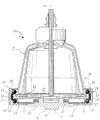
図示する態様において、全血の種々の成分を分離するための遠心分離機10は、閉コーン形状(ベル形状)分離ボウル2を取り付けるためのモーター駆動チャック1を含み、それによって、チャック1およびそれに取り付けられる分離ボウル2は、主(遠心)軸XAの周囲で回転できる。処理すべき全血のための1つまたはそれより多くの入口、および分離した血液成分を取り出す1つまたはそれより多くの出口が、ボウル2に設けられている。
In the illustrated embodiment, a
図示する態様において、ボウル2には、凸状(例えばコーン形状)の下側端部22が設けられている。この下側端部22は、コーン状の外周フランク23に包囲された状態で、チャック1内に連結される。
In the illustrated embodiment, the
図示する例示的な態様において、チャック1は、桶(vat)のような形状に構成されたチャック本体部11を備えていて、内部底面12および遠心分離モーターに面する外部下側面13を有する。この実施態様が運転されるとき、内部底面12および外部下側面13は、それぞれボウル2の下側端部22および遠心分離モーターに面する。
In the illustrated exemplary embodiment, the
従って、図示する例示的な態様において、チャック本体部11は、分離ボウル2の下側端部22を受け入れることができ、そのとき、チャックの周縁リム28が分離ボウル2の外周フランク23を包囲する。
Thus, in the illustrated exemplary embodiment, the chuck body 11 can receive the
以上に説明した部材の配置は、それ自体、当該技術分野において常套的であり、本明細書で更に詳しく説明する必要はない。 The arrangement of members described above is itself conventional in the art and need not be described in further detail herein.
1つの態様において、周縁リム28は連続構造体を有する(例えば、完全なリング形状体またはドーナツ形状体から構成される)。1つの態様において、周縁リム28は不連続構造体を有する(例えば、分離ボウルを掴む手指のように機能することが意図された、間隔をおいて配置された複数の弓状セグメント)。
In one embodiment, the
ある態様において、ボウル2をチャック1に固定する複数のクラッチシステム(または保持システム、clutching system)がチャック本体部11に設けられる。これらのクラッチシステムを、チャックの周囲で角度的に60°で等しく隔てて並べることができ、軸XAの周囲でボウル2をチャック1に取り付ける。1つの態様において、クラッチシステムは好ましくは6つ存在する。
In one embodiment, the chuck body 11 is provided with a plurality of clutch systems (or holding systems) that secure the
本明細書で説明する複数のクラッチシステム構成の1つの態様においては、それぞれのクラッチシステムは、次のものを含む。
−チャック本体部11に形成されたチャネル30。チャネル30は、周縁リム28の内側にアーチ状の経路を有する。
−チャネル30内に配置される一連の伝達体(例えば、複数の球体ボール)。当該一連の伝達体には、基端側伝達体16、末端側伝達体20、およびその間に位置する1または2以上の中間伝達体17、18、19が含まれる。
−遠心重錘15。この遠心重錘15は、付勢スプリング21の作用によって、および(または)チャック1が軸X A の周りに回転する際の遠心作用(下記で更に説明する)によって、基端側伝達体16に軸(X A )から外向きに向かう力を及ぼす。
In one aspect of the multiple clutch system configurations described herein , each clutch system includes:
A channel 30 formed in the chuck body 11; The channel 30 has an arcuate path inside the
A series of transmitters (eg, a plurality of spherical balls) disposed within the channel 30; The series of transmitters includes a
A
基端側伝達体16に外向きに作用する半径方向の力は、中間伝達体17、18、19を通して、末端側伝達体20に伝えることができる。それによって、末端側伝達体20は、回転軸XA radial force acting outwardly on the
1つの態様において、分離ボウルの外側底部側面は、チャック1に向かって開口する凸円錐形状を有する。このようにして、末端側伝達体20によって負荷される半径内向きの力から生じる“垂直”成分(即ち、軸X A に平行な方向における成分)が、ボウル2をチャック1に堅固に取り付けた状態を維持する。
In one embodiment, the outer bottom side of the separation bowl has a convex conical shape that opens toward the
図示する例示的な態様において、チャック本体部11内に形成されるチャネル30は、C形の経路(即ち、より一般的には、アーチ状または円弧状の経路)であって、次のものを含んでいる。
−軸X A から半径方向に延在して、基端側伝達体16を含む1または2以上の伝達体を受け入れる基端側部分31。基端側部分31は、図示した態様では、遠心重錘15も受け入れている。
−複数の中間伝達体を受け入れる中間部分32。中間伝達体とは、例えば、基端側達体16と末端側伝達体20との間に存在する3つの伝達体17、18、19である。チャネルの中間部分32は、軸X A と平行な方向に延在している。
−末端側伝達体20を含む1または2以上の伝達体を受け入れる末端側部分33。末端側部分33は、軸X A から半径方向に延在している。
In the exemplary embodiment shown, the channel 30 formed in the chuck body 11 is a C-shaped path (ie, more generally, an arched or arcuate path) comprising: Contains .
A
An
A
本明細書において、チャネル30、および回転する伝達体16〜20(および重錘体15)を“受け入れる”(即ち、収容する)チャネルの部分31、32、33とは、次のことを意味している。すなわち、基端側伝達体16から(即ち、遠心重錘15/スプリング21から)、末端側伝達体20へと(即ち、ボウル2のフランク23へと)、スラスト(即ち、力)を伝達する効果を実行すべく、チャネルに沿って少なくとも僅かに動くことができるように、伝達体は、チャネル内に入れられている。
As used herein , the
図示する態様において、伝達体は鋼ボールのようなボールであるが、例えばローラーのような低い摩擦で、動きおよび力を適切に伝えることができる他の伝達体を用いることができる。 In the embodiment shown, the transmitter is a ball, such as a steel ball, but other transmitters that can properly transmit motion and force with low friction, such as a roller, can be used.
1つの態様において、チャネルの基端側部分31に収納される伝達体(即ち、図示する例示的な態様においては、基端側伝達体16、およびそれに作用する遠心重錘15)の合計質量は、チャネルの末端側部分33に収納される伝達体(即ち、図示する例示的な態様においては、末端側伝達体20)の合計質量よりも大きい。そのような質量の違いは、関連する個々の部材の質量および/または数に基づき、達成することができる。例えば、チャネル30の基端側部分31における伝達体の数を、チャネル30の末端側部分33における伝達体の数よりも多くする。また、基端側伝達体16が遠心重錘15の役割を兼ねていてもよく、このようにすると、別の要素として遠心重錘15を供給することが不要になる。
In one embodiment, the total mass of the transmitter housed in the
遠心分離機10の運転中で、チャックの回転速度が小さい場合には、水平のチャネル部分31内で基端側伝達体16に作用する重錘15によって生み出される遠心力は、無視できる。これらの状況において、弾性部材(例えばスプリング)21が、基端側伝達体16に外向きの弾性力を及ぼす(当該弾性力は、中間伝達体17、18、19を通して末端側伝達体20に伝えられる)。この弾性力は、ボウル2をチャック1に堅固に取り付けた状態を維持するのに十分な力をもって、末端側達体20をボウル2のコーン形状下側側面23上に押圧する。
When the
チャックの回転速度が増すにつれて、弾性部材21が基端側伝達体16に及ぼすスプリング力に対して、重錘15による遠心力が徐々に加重されていき、大きい回転速度では支配的となる。
As the rotation speed of the chuck increases, the centrifugal force by the
チャネル30の基端側部分31内の伝達体の質量によって発生する遠心力は、チャネル30の末端側部分33内の伝達体の質量によって発生する遠心力に勝り、その結果、チャックの回転速度が増すにつれて増加する力で、末端側伝達体20をボウル2の外周フランク23に対してしっかりと押しやり、チャックにボウル2を固定する。
The centrifugal force generated by the mass of the transmitter in the
ボウル2の下側端部22におけるフランク23の傾斜した凸円錐形状は、末端側伝達体20が及ぼす内向きの力を、強い下向き成分に変換する。即ち、軸X A に平行な方向でチャック1に向かう強い力が、ボウル2をチャック1に堅固に取り付けた状態に維持する。
The inclined convex cone shape of the
このようにして、どのようなチャックの回転速度であっても、ボウル2は、所定位置に堅固に固定され、チャック1に取り付けたままに維持される。
In this way, the
ボウル2を(静止した)チャック1に連結するには、ボウル2の下側部をチャックの桶状の空間に単に滑り込ませる。そのために、まず、スプリング21によって生じる適度な反力に抗して、上記固定メカニズムの末端側伝達体20を拡げる。次に、スプリング21によって生じた弾性力により、末端側伝達体20を再びフランク23にスナップ係合させる。スプリング21の作用により伝達体20からフランク23に作用する弾性反力からボウルを解放させる補足的な動作を行えば、ボウル2をチャック1から簡単に外すことができる。
To connect the
レバーまたはヒンジを用いないため、本明細書のチャック構造体はより簡単に製造および組立作業をすることを可能にする。更に、本明細書のチャック構造体は、悪環境に対するより高い保護性を提供し、血液および埃による汚染を防ぐ。実際に、ボウル2をチャック1から離脱する場合、末端側伝達体20はチャネル30を密閉して塞ぎ、チャックの内側部分を外部環境から封止する。
Because no levers or hinges are used, the chuck structure herein allows for easier manufacturing and assembly operations. Further, the chuck structure herein provides greater protection against adverse environments and prevents contamination with blood and dust. In fact, when the
本発明の基本原理を損なうことなく、例のみによって説明したことを参照して詳細および態様を変更することができ、そのような変更が相当なものであっても、添付の請求項によって規定される本発明の範囲から逸脱するものではない。 Details and aspects may be altered with reference to what has been described by way of example only, without departing from the basic principles of the invention, even if such modifications are substantial, as defined by the appended claims. It does not depart from the scope of the present invention.
Claims (13)
当該チャック本体部(11)は、当該チャック(1)の周縁リム(28)が遠心分離ボウル(2)の外周フランク(23)を包囲した状態において、遠心分離ボウル(2)の下側端部(22)を受け入れて固定し、
当該チャックは、遠心分離ボウル(2)をチャック(1)に固定することにおいて、遠心分離ボウル(2)の外周フランク(23)と協動する少なくとも1つのクラッチシステムを含んでおり、
当該クラッチシステムは、
−上記チャック本体部(11)内に形成され上記周縁リム(28)の内側にアーチ状の経路を有するチャネル(30)と、
−上記チャネル(30)内に配置されていて、基端側伝達体(16)および末端側伝達体(20)を含む一連の伝達体(16、17、18、19、20)と、を含んでおり、
上記回転軸(X A )の回りに回転している間、基端側伝達体(16)に作用し、上記回転軸(X A )から外側に向かう力が、チャネル内で一連の伝達体(16、17、18、19、20)を通して、末端側伝達体(20)まで伝達され、これにより、当該末端側伝達体(20)を上記回転軸(X A )に向かって内向き付勢し、その結果、遠心分離ボウル(2)の外周フランク(23)を掴んで、遠心分離ボウル(2)を当該チャック(1)に固定する、ことを特徴とするチャック。
The centrifuge bowl (2), a chuck for rotating around a rotation axis (X A) (1), said chuck, tub-shaped chuck body portion (11) Te containing Ndei,
The chuck body (11) has a lower end of the centrifuge bowl (2) in a state where the peripheral rim (28) of the chuck (1) surrounds the outer peripheral flank (23) of the centrifuge bowl (2). Accept (22) and fix,
The chuck includes at least one clutch system that cooperates with the outer peripheral flank (23) of the centrifuge bowl (2) in securing the centrifuge bowl (2) to the chuck (1) ;
The clutch system
A channel (30) formed in the chuck body (11) and having an arched path inside the peripheral rim (28) ;
A series of transmitters (16, 17, 18, 19, 20) disposed within the channel (30) and including a proximal transmitter (16) and a distal transmitter (20); And
While rotating around the rotation axis (X A), acts on the base end side transmission member (16), a force directed outward from the rotating shaft (X A) is a series of transfer body in the channel ( 16, 17, 18, 19, 20) to the distal transmission body (20), thereby urging the distal transmission body (20) inward toward the rotation axis (X A ). As a result, the chuck characterized in that the outer peripheral flank (23) of the centrifuge bowl (2) is gripped and the centrifuge bowl (2) is fixed to the chuck (1) .
It said at least part component of force directed outwardly, comprising a resilient element (21) to act on the base end side transmission member (16), according to claim 1 chuck according.
It said at least part component of force directed outwardly, comprising a centrifugal weight (15) to act on the base end side transmission member (16), according to claim 1 chuck according.
当該遠心重錘(15)および弾性要素(21)は、それぞれが、上記外側に向かう力の各成分を上記基端側伝達体(16)に作用させる、請求項1記載のチャック。
The chuck, both elastic element for biasing the centrifugal weight (15) and the centrifugal weight (15) (21) Te containing Ndei,
The chuck according to claim 1, wherein each of the centrifugal weight (15) and the elastic element (21) causes each component of the outward force to act on the proximal transmission body (16) .
The chuck according to claim 3 or 4, wherein the centrifugal weight (15) is a member different from the proximal-side transmission body (16).
The chuck according to claim 5, wherein the centrifugal weight (15) is a rod slidably disposed in a radial hole of the chuck.
−上記回転軸(X A )から半径方向に延在していて、上記基端側伝達体(16)を受け入れる基端側部分(31)と、
−上記回転軸(X A )と平行に延在していて、上記一連の伝達体(16、17、18、19、20)における、基端側伝達体(16)と末端側伝達体(20)との間に位置する伝達体(17、18、19)を受け入れる中間部分(32)と、
−上記回転軸(X A )から半径方向に延在していて、上記末端側伝達体(20)を受け入れる末端側部分(33)と、を含む請求項1〜6のいずれか1つに記載のチャック。
The channel (30) formed in the chuck body (11) and having an arcuate path inside the peripheral rim (28) ,
A proximal end portion (31) extending radially from the rotational axis (X A ) and receiving the proximal end transmission body (16);
The base-side transmitter (16) and the distal-side transmitter (20) in the series of transmitters (16, 17, 18, 19, 20) extending in parallel with the rotation axis (X A ). Intermediate portion (32) for receiving the transmission body (17, 18, 19) located between
A distal portion (33) extending radially from the rotational axis (X A ) and receiving the distal transmission body (20), according to any one of claims 1-6. Chuck.
チャネル(30)の基端側部分(31)内で遠心力を受ける遠心重錘(15)と基端側伝達体(16)の合計質量は、チャネル(30)の末端側部分(33)内で遠心力を受ける末端側伝達体(20)の合計質量よりも大きい、請求項7記載のチャック。
The proximal end portion (31) and the distal end portion (33) of the channel (30) include a proximal transmission body (16) and a distal end that receive a centrifugal force while rotating around the rotation axis (X A ). Receiving the side transmitter (20), centrifugal weight (15),
The total mass of the centrifugal weight (15) and the proximal transmitter (16) that receive a centrifugal force in the proximal portion (31) of the channel (30) is within the distal portion (33) of the channel (30). The chuck according to claim 7, wherein the chuck is larger than a total mass of the distal transmission body (20) subjected to centrifugal force .
The clutch system according to claim 1, comprising a plurality of the clutch systems, wherein the plurality of clutch systems are arranged at equal angular intervals around the rotation axis (X A ) . Chuck.
The chuck according to any one of claims 1 to 9, comprising six clutch systems.
The chuck according to any one of claims 1 to 10, wherein the peripheral rim (28) is constituted by a continuous structure .
The chuck according to any one of claims 1 to 11, wherein the transmission body (16, 17, 18, 19, 20) is a ball .
遠心分離ボウル(2)は、上記チャック(1)に向かって開口する凸円錐形状を為しており、
上記一連の伝達体を通して、末端側伝達体(20)まで伝達され、当該末端側伝達体(20)を上記回転軸(X A )に向かって内向きに付勢することで外周フランク(23)を掴む上記力が、遠心分離ボウル(2)をチャック(1)に押し付ける力を生じさせる、組合せ。 A combination of the chuck according to any one of claims 1 to 12 and the centrifuge bowl (2),
The centrifuge bowl (2) has a convex conical shape opening toward the chuck (1),
It is transmitted to the terminal side transmission body (20) through the series of transmission bodies, and the peripheral side flank (23) is urged inward toward the rotating shaft (X A ) by urging the terminal side transmission body (20 ). A combination in which the above-described force of gripping the force produces a force that presses the centrifuge bowl (2) against the chuck (1) .
Applications Claiming Priority (2)
| Application Number | Priority Date | Filing Date | Title |
|---|---|---|---|
| EP08157932.8 | 2008-06-10 | ||
| EP08157932A EP2138237B1 (en) | 2008-06-10 | 2008-06-10 | A securing mechanism, particularly for blood separation centrifuges and the like |
Publications (3)
| Publication Number | Publication Date |
|---|---|
| JP2010042398A JP2010042398A (en) | 2010-02-25 |
| JP2010042398A5 JP2010042398A5 (en) | 2012-07-26 |
| JP5199186B2 true JP5199186B2 (en) | 2013-05-15 |
Family
ID=39870607
Family Applications (1)
| Application Number | Title | Priority Date | Filing Date |
|---|---|---|---|
| JP2009138348A Expired - Fee Related JP5199186B2 (en) | 2008-06-10 | 2009-06-09 | Mounting mechanism, especially for centrifuges that separate blood |
Country Status (4)
| Country | Link |
|---|---|
| US (3) | US7993257B2 (en) |
| EP (1) | EP2138237B1 (en) |
| JP (1) | JP5199186B2 (en) |
| DE (1) | DE602008004637D1 (en) |
Families Citing this family (7)
| Publication number | Priority date | Publication date | Assignee | Title |
|---|---|---|---|---|
| US7998052B2 (en) * | 2006-03-07 | 2011-08-16 | Jacques Chammas | Rotor defining a fluid separation chamber of varying volume |
| US8506825B2 (en) | 2006-11-27 | 2013-08-13 | Sorin Group Italia S.R.L. | Method and apparatus for controlling the flow rate of washing solution during the washing step in a blood centrifugation bowl |
| EP2138237B1 (en) * | 2008-06-10 | 2011-01-19 | Sorin Group Italia S.r.l. | A securing mechanism, particularly for blood separation centrifuges and the like |
| PT2456565T (en) * | 2009-07-24 | 2017-02-28 | Duerr Systems Ag | Rotary atomiser comprising a spraying cup and a securing retention mechanism |
| US9308314B2 (en) | 2011-04-08 | 2016-04-12 | Sorin Group Italia S.R.L. | Disposable device for centrifugal blood separation |
| US10039876B2 (en) | 2014-04-30 | 2018-08-07 | Sorin Group Italia S.R.L. | System for removing undesirable elements from blood using a first wash step and a second wash step |
| US10617804B2 (en) | 2014-10-23 | 2020-04-14 | Sorin Group Italia S.R.L. | Integrated autotransfusion bowl and fluid line organizer |
Family Cites Families (57)
| Publication number | Priority date | Publication date | Assignee | Title |
|---|---|---|---|---|
| US1385306A (en) * | 1918-04-08 | 1921-07-19 | Courtaulds Ltd | Spinning-box for artificial silk |
| US3317127A (en) * | 1945-03-02 | 1967-05-02 | Little Inc A | Centrifuge |
| US2536793A (en) * | 1945-03-02 | 1951-01-02 | Separator Ab | Sealing device for centrifugal separators |
| US2835517A (en) * | 1953-09-25 | 1958-05-20 | Uster Spindel Motoren Maschf | Holding device |
| US3409213A (en) * | 1967-01-23 | 1968-11-05 | 500 Inc | Rotary seal and centrifuge incorporation |
| US3565330A (en) * | 1968-07-11 | 1971-02-23 | Cryogenic Technology Inc | Rotary seal and centrifuge incorporating same |
| US3785549A (en) * | 1972-07-31 | 1974-01-15 | Haemonetics Corp | Centrifuge chuck for disposable, snap-in centrifuge rotor |
| US4140268A (en) * | 1977-03-15 | 1979-02-20 | Haemo-Transfer S.A. | Centrifugating device for biological liquids, having a rotatable container, and supporting bracket therefor |
| US4795419A (en) * | 1985-10-11 | 1989-01-03 | Kardiothor, Inc. | Centrifuge |
| US4718888A (en) * | 1986-03-10 | 1988-01-12 | Cardiovascular Systems, Inc. | Centrifuge bowl mount |
| US4668214A (en) | 1986-06-09 | 1987-05-26 | Electromedics, Inc. | Method of washing red blood cells |
| EP0277994B1 (en) | 1986-08-11 | 1991-09-04 | BAXTER INTERNATIONAL INC. (a Delaware corporation) | Blood cell washing systems and methods |
| IT1202514B (en) * | 1987-02-10 | 1989-02-09 | Dideco Spa | SPINDLE FOR FASTENING OF CELL FOR CENTRIFUGATION OF BLOOD, AND SIMILAR |
| US4889524A (en) * | 1987-09-04 | 1989-12-26 | Haemonetics Corporation | Portable centrifuge apparatus |
| DE8816668U1 (en) * | 1988-07-04 | 1990-02-22 | Paul Forkardt GmbH & Co KG, 4000 Düsseldorf | Power operated chuck |
| IT1230356B (en) * | 1989-07-14 | 1991-10-18 | Dideco Spa | BLOCK SPINDLE BLOCKING DEVICE FOR BLOOD CENTRIFUGATION. |
| IT1231023B (en) * | 1989-07-31 | 1991-11-08 | Dideco Spa | CELL CONTAINMENT CLOSING DEVICE FOR CENTRIFUGING BLOOD IN A CENTRIFUGAL MACHINE |
| US5137221A (en) * | 1990-10-04 | 1992-08-11 | Axis Usa, Inc. | Rapidly changeable chucks for holding stators in stator processing apparatus |
| US5273517A (en) | 1991-07-09 | 1993-12-28 | Haemonetics Corporation | Blood processing method and apparatus with disposable cassette |
| DE4126341C1 (en) | 1991-08-09 | 1993-01-28 | Fresenius Ag, 6380 Bad Homburg, De | |
| US5730883A (en) | 1991-12-23 | 1998-03-24 | Baxter International Inc. | Blood processing systems and methods using apparent hematocrit as a process control parameter |
| US5423738A (en) | 1992-03-13 | 1995-06-13 | Robinson; Thomas C. | Blood pumping and processing system |
| DE69310995T2 (en) * | 1992-04-29 | 1997-09-04 | Cobe Lab | Centrifuge with a single swing arm to hold a stator tube |
| US5385539A (en) | 1992-06-30 | 1995-01-31 | Advanced Haemotechnologies | Apparatus for monitoring hematocrit levels of blood |
| SE9202937D0 (en) | 1992-10-07 | 1992-10-07 | Siemens Elema Ab | FREQUENCY ADAPTIVE HEART STIMULATOR |
| CH687505A5 (en) * | 1993-01-29 | 1996-12-31 | Elp Rochat | Centrifugal separator for fluids. |
| US5383911A (en) | 1993-01-29 | 1995-01-24 | Siemens Pacesetter, Inc. | Rate-responsive pacemaker having selectable response to arm movement and pedal impacts |
| DE69425966T2 (en) | 1993-04-27 | 2001-03-29 | Haemonetics Corp., Braintree | Apheresis device |
| US5379775A (en) | 1993-10-15 | 1995-01-10 | Medtronic, Inc. | Low amplitude pacing artifact detection apparatus and method using isolation amplifier to minimize distortion |
| US5505683A (en) * | 1993-12-10 | 1996-04-09 | Haemonetics Corporation | Centrifuge bowl gripping apparatus having a retaining arm with a stationary jaw and a moveable jaw |
| US5478479A (en) | 1994-05-20 | 1995-12-26 | Haemonetics Corporation | Two-stage cell wash process controlled by optical sensor |
| US5733253A (en) * | 1994-10-13 | 1998-03-31 | Transfusion Technologies Corporation | Fluid separation system |
| US5591113A (en) * | 1994-10-31 | 1997-01-07 | Cobe Laboratories, Inc. | Centrifugally assisted centrifuge bowl mount |
| US5658231A (en) | 1995-09-21 | 1997-08-19 | Haemonetics Corporation | Mechanism for securing a separation bowl to a mechanical chuck |
| ATE217212T1 (en) * | 1995-12-07 | 2002-05-15 | Bristol Myers Squibb Co | CENTRIFUGE |
| US5851169A (en) * | 1996-01-31 | 1998-12-22 | Medtronic Electromedics, Inc. | Rotary plate and bowl clamp for blood centrifuge |
| JPH09320158A (en) * | 1996-05-27 | 1997-12-12 | Pioneer Electron Corp | Disk-chucking mechanism |
| DE19746914C2 (en) | 1996-10-25 | 1999-07-22 | Peter Dr Geigle | Centrifugation unit |
| WO1998029149A1 (en) | 1997-01-03 | 1998-07-09 | Shettigar U Ramakrishna | Intraoperative blood salvaging system and method |
| US5876611A (en) | 1997-06-16 | 1999-03-02 | Shettigar; U. Ramakrishna | Intraoperative blood salvaging system and method |
| SE9700495D0 (en) | 1997-02-12 | 1997-02-12 | Omega Medicinteknik Ab | Method and round bag system and centrifuge for blood treatment |
| US5964690A (en) * | 1997-03-19 | 1999-10-12 | Medtronic, Inc. | Mechanism for fixing a blood centrifuge bowl to a rotating spindle |
| DE69837541T2 (en) | 1997-05-20 | 2007-12-13 | Zymequest, Inc., Beverly | Rotary seal for cell treatment systems |
| US5919125A (en) | 1997-07-11 | 1999-07-06 | Cobe Laboratories, Inc. | Centrifuge bowl for autologous blood salvage |
| DE19802321C2 (en) | 1998-01-23 | 2000-05-11 | Fresenius Ag | Method and device for the preparation of intra- or post-operative blood loss for autotransfusion |
| IT1302015B1 (en) | 1998-08-07 | 2000-07-20 | Dideco Spa | AUTOMATIC CELL CONTROL SYSTEM FOR BLOOD CENTRIFUGATION. |
| US6629919B2 (en) | 1999-06-03 | 2003-10-07 | Haemonetics Corporation | Core for blood processing apparatus |
| JP4064014B2 (en) * | 1999-09-01 | 2008-03-19 | 株式会社テック・ヤスダ | Base |
| US6605028B2 (en) | 2001-04-09 | 2003-08-12 | Medtronic, Inc. | Blood centrifuge having integral heating to control cellular component temperature |
| ITMI20010899A1 (en) | 2001-04-30 | 2002-10-30 | Dideco Spa | CELL WASHING PHASE CONTROL SYSTEM FOR BLOOD CENTRIFUGATION |
| US7186230B2 (en) | 2002-03-04 | 2007-03-06 | Therakos, Inc | Method and apparatus for the continuous separation of biological fluids into components |
| ITMI20031715A1 (en) | 2003-09-05 | 2005-03-06 | Dideco Spa | CONTROL DEVICE IN THE DIFFERENTIATED COLLECTION OF THE |
| JP4304031B2 (en) * | 2003-09-11 | 2009-07-29 | テルモ株式会社 | Rotation drive device for centrifuge |
| US7998052B2 (en) * | 2006-03-07 | 2011-08-16 | Jacques Chammas | Rotor defining a fluid separation chamber of varying volume |
| US8506825B2 (en) | 2006-11-27 | 2013-08-13 | Sorin Group Italia S.R.L. | Method and apparatus for controlling the flow rate of washing solution during the washing step in a blood centrifugation bowl |
| JP2009291335A (en) * | 2008-06-04 | 2009-12-17 | Terumo Corp | Centrifugal separator and blood component collecting apparatus |
| EP2138237B1 (en) * | 2008-06-10 | 2011-01-19 | Sorin Group Italia S.r.l. | A securing mechanism, particularly for blood separation centrifuges and the like |
-
2008
- 2008-06-10 EP EP08157932A patent/EP2138237B1/en active Active
- 2008-06-10 DE DE602008004637T patent/DE602008004637D1/en active Active
-
2009
- 2009-05-27 US US12/472,825 patent/US7993257B2/en active Active
- 2009-06-09 JP JP2009138348A patent/JP5199186B2/en not_active Expired - Fee Related
-
2011
- 2011-06-29 US US13/172,220 patent/US8262552B2/en active Active
-
2012
- 2012-08-16 US US13/587,153 patent/US8485957B2/en active Active
Also Published As
| Publication number | Publication date |
|---|---|
| US8485957B2 (en) | 2013-07-16 |
| JP2010042398A (en) | 2010-02-25 |
| US20110256999A1 (en) | 2011-10-20 |
| US8262552B2 (en) | 2012-09-11 |
| EP2138237A1 (en) | 2009-12-30 |
| EP2138237B1 (en) | 2011-01-19 |
| US20090305863A1 (en) | 2009-12-10 |
| US7993257B2 (en) | 2011-08-09 |
| DE602008004637D1 (en) | 2011-03-03 |
| US20130079211A1 (en) | 2013-03-28 |
Similar Documents
| Publication | Publication Date | Title |
|---|---|---|
| JP5199186B2 (en) | Mounting mechanism, especially for centrifuges that separate blood | |
| JP2010042398A5 (en) | ||
| US8051960B2 (en) | Braking apparatus for blind | |
| CN208233359U (en) | Power suit | |
| GB2524285A (en) | Cleaner head | |
| KR20160136360A (en) | Cleaning appliance | |
| WO2017056650A1 (en) | Tube rack for centrifuge | |
| JPH09506558A (en) | Removable nosepiece for chucks and similar tool holders | |
| JP4187273B2 (en) | Mechanism for securing the vessel for the blood centrifuge to the rotating spindle | |
| JP2009082922A (en) | Centrifuge rotor locking apparatus, rotor locking mechanism and rotor assembly | |
| JP5762419B2 (en) | Support and drive assembly for blade carrier disk of rotary multi-plate mower | |
| JP5839909B2 (en) | Chuck mechanism for mounting a dental tool on a dental turbine handpiece | |
| JP2000107643A5 (en) | ||
| JP3861476B2 (en) | centrifuge | |
| JP4613905B2 (en) | Centrifuge rotor and centrifuge with the same | |
| US20050221971A1 (en) | Attachment and release apparatus and method | |
| KR20130071654A (en) | Spindle locking apparatus | |
| JP4971602B2 (en) | Tool holder | |
| KR101859162B1 (en) | Propeller attachable and detachable apparatus for drone | |
| JP2004057242A (en) | Cleaning device | |
| JP2001316083A (en) | Device for restricting upper-side rotating speed of balancing hoist | |
| JP4751616B2 (en) | Cleaning method and apparatus for tool mounting apparatus | |
| JP2006159005A (en) | Centrifugal machine | |
| JP2008307495A (en) | Rotor for centrifuge and centrifuge equipped therewith | |
| JPH1156U (en) | Dental handpiece |
Legal Events
| Date | Code | Title | Description |
|---|---|---|---|
| A621 | Written request for application examination |
Free format text: JAPANESE INTERMEDIATE CODE: A621 Effective date: 20110830 |
|
| A977 | Report on retrieval |
Free format text: JAPANESE INTERMEDIATE CODE: A971007 Effective date: 20120316 |
|
| A131 | Notification of reasons for refusal |
Free format text: JAPANESE INTERMEDIATE CODE: A131 Effective date: 20120327 |
|
| A524 | Written submission of copy of amendment under article 19 pct |
Free format text: JAPANESE INTERMEDIATE CODE: A524 Effective date: 20120607 |
|
| TRDD | Decision of grant or rejection written | ||
| A01 | Written decision to grant a patent or to grant a registration (utility model) |
Free format text: JAPANESE INTERMEDIATE CODE: A01 Effective date: 20130108 |
|
| A61 | First payment of annual fees (during grant procedure) |
Free format text: JAPANESE INTERMEDIATE CODE: A61 Effective date: 20130207 |
|
| FPAY | Renewal fee payment (event date is renewal date of database) |
Free format text: PAYMENT UNTIL: 20160215 Year of fee payment: 3 |
|
| R150 | Certificate of patent or registration of utility model |
Ref document number: 5199186 Country of ref document: JP Free format text: JAPANESE INTERMEDIATE CODE: R150 Free format text: JAPANESE INTERMEDIATE CODE: R150 |
|
| R250 | Receipt of annual fees |
Free format text: JAPANESE INTERMEDIATE CODE: R250 |
|
| R250 | Receipt of annual fees |
Free format text: JAPANESE INTERMEDIATE CODE: R250 |
|
| R250 | Receipt of annual fees |
Free format text: JAPANESE INTERMEDIATE CODE: R250 |
|
| R250 | Receipt of annual fees |
Free format text: JAPANESE INTERMEDIATE CODE: R250 |
|
| R250 | Receipt of annual fees |
Free format text: JAPANESE INTERMEDIATE CODE: R250 |
|
| LAPS | Cancellation because of no payment of annual fees |