JP5185024B2 - Communication system, its dependent stations, and relay transmission method - Google Patents
Communication system, its dependent stations, and relay transmission method Download PDFInfo
- Publication number
- JP5185024B2 JP5185024B2 JP2008220501A JP2008220501A JP5185024B2 JP 5185024 B2 JP5185024 B2 JP 5185024B2 JP 2008220501 A JP2008220501 A JP 2008220501A JP 2008220501 A JP2008220501 A JP 2008220501A JP 5185024 B2 JP5185024 B2 JP 5185024B2
- Authority
- JP
- Japan
- Prior art keywords
- station
- data
- dependent
- frame
- relay
- Prior art date
- Legal status (The legal status is an assumption and is not a legal conclusion. Google has not performed a legal analysis and makes no representation as to the accuracy of the status listed.)
- Expired - Fee Related
Links
Images


Classifications
-
- H—ELECTRICITY
- H04—ELECTRIC COMMUNICATION TECHNIQUE
- H04L—TRANSMISSION OF DIGITAL INFORMATION, e.g. TELEGRAPHIC COMMUNICATION
- H04L1/00—Arrangements for detecting or preventing errors in the information received
- H04L1/12—Arrangements for detecting or preventing errors in the information received by using return channel
- H04L1/16—Arrangements for detecting or preventing errors in the information received by using return channel in which the return channel carries supervisory signals, e.g. repetition request signals
- H04L1/18—Automatic repetition systems, e.g. Van Duuren systems
- H04L1/1829—Arrangements specially adapted for the receiver end
-
- H—ELECTRICITY
- H04—ELECTRIC COMMUNICATION TECHNIQUE
- H04H—BROADCAST COMMUNICATION
- H04H20/00—Arrangements for broadcast or for distribution combined with broadcast
- H04H20/02—Arrangements for relaying broadcast information
- H04H20/08—Arrangements for relaying broadcast information among terminal devices
-
- H—ELECTRICITY
- H04—ELECTRIC COMMUNICATION TECHNIQUE
- H04L—TRANSMISSION OF DIGITAL INFORMATION, e.g. TELEGRAPHIC COMMUNICATION
- H04L1/00—Arrangements for detecting or preventing errors in the information received
- H04L1/0001—Systems modifying transmission characteristics according to link quality, e.g. power backoff
- H04L1/0023—Systems modifying transmission characteristics according to link quality, e.g. power backoff characterised by the signalling
- H04L1/0027—Scheduling of signalling, e.g. occurrence thereof
-
- H—ELECTRICITY
- H04—ELECTRIC COMMUNICATION TECHNIQUE
- H04L—TRANSMISSION OF DIGITAL INFORMATION, e.g. TELEGRAPHIC COMMUNICATION
- H04L1/00—Arrangements for detecting or preventing errors in the information received
- H04L1/0001—Systems modifying transmission characteristics according to link quality, e.g. power backoff
- H04L1/0023—Systems modifying transmission characteristics according to link quality, e.g. power backoff characterised by the signalling
- H04L1/0028—Formatting
-
- H—ELECTRICITY
- H04—ELECTRIC COMMUNICATION TECHNIQUE
- H04L—TRANSMISSION OF DIGITAL INFORMATION, e.g. TELEGRAPHIC COMMUNICATION
- H04L1/00—Arrangements for detecting or preventing errors in the information received
- H04L1/0078—Avoidance of errors by organising the transmitted data in a format specifically designed to deal with errors, e.g. location
- H04L1/0079—Formats for control data
-
- H—ELECTRICITY
- H04—ELECTRIC COMMUNICATION TECHNIQUE
- H04L—TRANSMISSION OF DIGITAL INFORMATION, e.g. TELEGRAPHIC COMMUNICATION
- H04L1/00—Arrangements for detecting or preventing errors in the information received
- H04L1/12—Arrangements for detecting or preventing errors in the information received by using return channel
- H04L1/16—Arrangements for detecting or preventing errors in the information received by using return channel in which the return channel carries supervisory signals, e.g. repetition request signals
- H04L1/18—Automatic repetition systems, e.g. Van Duuren systems
- H04L1/1809—Selective-repeat protocols
-
- H—ELECTRICITY
- H04—ELECTRIC COMMUNICATION TECHNIQUE
- H04H—BROADCAST COMMUNICATION
- H04H20/00—Arrangements for broadcast or for distribution combined with broadcast
- H04H20/42—Arrangements for resource management
-
- H—ELECTRICITY
- H04—ELECTRIC COMMUNICATION TECHNIQUE
- H04W—WIRELESS COMMUNICATION NETWORKS
- H04W40/00—Communication routing or communication path finding
Landscapes
- Engineering & Computer Science (AREA)
- Signal Processing (AREA)
- Computer Networks & Wireless Communication (AREA)
- Quality & Reliability (AREA)
- Mobile Radio Communication Systems (AREA)
- Radio Relay Systems (AREA)
Description
本発明は、制御局が複数の従属局宛てのデータをスーパーフレーム毎にブロードキャスト送信する技術に関するものである。 The present invention, control station to a technique you send broadcast data of the dependent station addressed several per superframe.
無線通信システムは、可搬性の優れたネットワークシステムとして利用され、無線通信区間の伝送速度の向上や携帯端末の普及、モバイル通信に適したアプリケーションの出現などにより、飛躍的な普及を見せている。特に、室内や構内などの比較的近距離においてコンピュータ機器類を無線接続する方式として、2.4GHzや5GHz帯の電波を用いたWLANシステムが広く普及している。その技術仕様は、IEEE802.11標準規格群で規定されている。 A wireless communication system is used as a network system having excellent portability, and is rapidly spreading due to an improvement in transmission speed in a wireless communication section, a spread of mobile terminals, and the emergence of applications suitable for mobile communication. In particular, WLAN systems that use radio waves in the 2.4 GHz and 5 GHz bands are widely used as a method for wirelessly connecting computer devices in a relatively short distance such as indoors or premises. The technical specifications are defined in the IEEE 802.11 standard group.
また、コンピュータ周辺機器のみならずデジタルスチルカメラやデジタルビデオカメラなどのコンシューマ機器と、プリンタや携帯電話などを接続するような機器間無線通信に対する要求も高まっている。現在、これらは一般的に、USBやIEEE1394など有線ケーブルによって接続される形態が採用されているが、利用者が簡便にこれらの機器を接続できる方法として無線接続によるものも考えられている。 In addition, there is an increasing demand for not only computer peripheral devices but also consumer devices such as digital still cameras and digital video cameras, and wireless communication between devices such as connecting a printer or a mobile phone. At present, these are generally connected by a wired cable such as USB or IEEE1394, but a method by which a user can easily connect these devices is also considered by wireless connection.
このような極近距離における機器間無線通信方式はWLANと異なり、たかだか10メートル程度と考えられる一人の人間の周辺環境内での無線接続を志向しており、WLANとは区別されWPANと呼ばれる。現在、WPANに関しては、UWB(Ultra Wide Band)通信方式を使用するものとして標準規格策定団体であるECMA internationalからECMA-368標準規格として物理層及びMAC層の仕様が定義されている。更に、このECMA-368の上位で動作するプロトコルとしてはWireless USB規格などが定義されている。 The wireless communication system between devices at such a short distance is different from WLAN, and is aimed at wireless connection within the environment of one person, which is considered to be about 10 meters at the most. It is distinguished from WLAN and called WPAN. At present, regarding the WPAN, specifications of the physical layer and the MAC layer are defined as ECMA-368 standards from ECMA international, which is a standard-defining organization, that uses UWB (Ultra Wide Band) communication methods. Furthermore, the Wireless USB standard is defined as a protocol that operates above the ECMA-368.
WLANやWPANでは複数の無線端末が同時に無線フレーム送信することにより発生する恐れのある無線フレームの衝突を防止するために、各無線端末が無線メディアへアクセスするタイミングの制御が行われる。この制御方式を定めたものがメディアアクセス制御(MAC)プロトコルである。このようなMACプロトコルには様々な方式が存在するが、代表的な分類方法として非同期式データ転送方式と同期式データ転送方式の2つに分類することができる。 In WLAN and WPAN, in order to prevent collision of radio frames that may occur when a plurality of radio terminals transmit radio frames at the same time, the timing at which each radio terminal accesses the radio medium is controlled. The media access control (MAC) protocol defines this control method. There are various methods for such a MAC protocol, but as a typical classification method, it can be classified into two types, an asynchronous data transfer method and a synchronous data transfer method.
一般に、非同期式データ転送ではCSMA/CA(Carrier Sense Multiple Access/Collision Avoidance)プロトコルなどによってメディアへのアクセス権を得た端末がデータ送信を行う。そして、当該データの宛先端末は当該データを正しく受信した場合、一般にアクノレッジフレームと呼ばれる認識応答を送信端末に対して返送する。データ送信端末はこの認識応答を受信した場合、データ転送が正常に完了したと判断する。逆に、この認識応答を受信しなかった場合、データ送信端末はデータ転送に失敗したと判断し、一定の期間後に当該データの再送を試みる。 In general, in asynchronous data transfer, a terminal that has obtained an access right to a medium through a CSMA / CA (Carrier Sense Multiple Access / Collision Avoidance) protocol transmits data. When the data destination terminal correctly receives the data, it returns a recognition response generally called an acknowledge frame to the transmitting terminal. When receiving the recognition response, the data transmitting terminal determines that the data transfer has been completed normally. On the other hand, when the recognition response is not received, the data transmitting terminal determines that the data transfer has failed and tries to retransmit the data after a certain period.
このようにして、非同期式データ転送方式では確実にデータを宛先端末に転送することが可能であるが、その反面、メディアアクセス権獲得の失敗や、上述したデータ再送などによりデータ転送の遅延量が変動する。ここでは、このようなデータ転送における遅延量の変動を遅延ジッタと呼ぶ。 In this way, the asynchronous data transfer method can reliably transfer the data to the destination terminal. However, on the other hand, the data transfer delay amount due to the failure to acquire the media access right or the above-mentioned data retransmission, etc. fluctuate. Here, such a variation in delay amount in data transfer is referred to as delay jitter.
尚、音声や動画像などを転送するアプリケーションは、データ転送に対して同期性或いは等時性を必要とするため、遅延ジッタが大きくなってしまう非同期式データ転送方式は、このようなアプリケーションには適していない。 Note that applications that transfer audio, video, etc. require synchronicity or isochronism with respect to data transfer, so asynchronous data transfer methods that increase delay jitter are not suitable for such applications. Not suitable.
一方、同期式データ転送方式では、各端末はTDMA(Time Division Multiple Access)プロトコルなどによって自局に割り当てられたタイムスロット内でデータ送信を行う。このようなプロトコルでは各端末は一定周期毎にデータ送信権を獲得することができるため、データ転送に対する遅延ジッタが小さい。従って、同期式データ転送方式は同期性或いは等時性を必要とするデータ転送に適している。 On the other hand, in the synchronous data transfer method, each terminal transmits data within a time slot assigned to itself by a TDMA (Time Division Multiple Access) protocol or the like. In such a protocol, each terminal can acquire the right to transmit data at regular intervals, so that the delay jitter for data transfer is small. Therefore, the synchronous data transfer method is suitable for data transfer that requires synchronization or isochronism.
更に、同期式データ転送方式では、データ転送における遅延ジッタを一定以内に収めるため、一般に送受信端末間で認識応答を交換したり、データ転送失敗時の再送処理を行ったりしない。このため、同期式データ転送方式では、通信状態によってはデータパケットが損失される場合が発生し得る。 Further, in the synchronous data transfer method, since the delay jitter in data transfer is kept within a certain range, generally, a recognition response is not exchanged between the transmitting and receiving terminals, and a retransmission process when data transfer fails is not performed. For this reason, in the synchronous data transfer method, a data packet may be lost depending on the communication state.
しかしながら、音声や動画像伝送では、通信の特性として常に、一定の平均転送速度と平均遅延を維持することが最優先されるため、ある程度のパケット損失が許容できるようにアプリケーションプロトコルが設計されている。 However, in audio and video transmission, maintaining the constant average transfer rate and average delay is always given the highest priority as communication characteristics, so the application protocol is designed to allow a certain amount of packet loss. .
このように、同期式データ転送方式では、音声や動画像のような同期性を必要とするアプリケーションに適している反面、パケット損失によるアプリケーションデータの消失が発生する。このようなデータ消失は再生される音声の途切れや動画像のブロックノイズなどを引き起こし、アプリケーション品質を劣化させてしまうという欠点があった。 As described above, the synchronous data transfer method is suitable for applications that require synchronization such as voice and moving images, but application data is lost due to packet loss. Such data loss has a drawback in that the quality of the application is deteriorated due to interruption of the reproduced sound, block noise of the moving image, and the like.
同期式データ転送方式におけるこのような問題を解決するために、同期性を維持しながらデータ消失の発生を抑制する信頼性の高い通信方式として、同一データを冗長的に複数回、転送する中継伝送方式が考えられている。そこで、このような中継伝送方式について説明する。 To solve such problems in synchronous data transfer systems, relay transmission that transfers the same data redundantly multiple times as a highly reliable communication system that suppresses the occurrence of data loss while maintaining synchronization A method is considered. Therefore, such a relay transmission method will be described.
図16は、中継伝送システムの構成の一例を示すシステム構成図である。このシステムは、例えば音声や動画像のような同期データの生成元としての制御局11と同期データの宛先となる4個の従属局12〜15から構成される。
FIG. 16 is a system configuration diagram illustrating an example of the configuration of the relay transmission system. This system is composed of, for example, a
図17は、中継伝送システムのメディアアクセスタイミングを示す図である。ここで、システムはアクセスプロトコルとしてTDMAを採用しており、メディアへのアクセスタイミングはスーパーフレーム21と呼ばれる一定周期を単位として管理される。このスーパーフレーム21は制御局11及び従属局12〜15がそれぞれデータ送信するためのタイムスロット31〜35に分割されている。
FIG. 17 is a diagram illustrating the media access timing of the relay transmission system. Here, the system employs TDMA as an access protocol, and the access timing to the medium is managed in units of a fixed period called a
スーパーフレーム21において、タイムスロット31は、制御局11がデータ送信する時間、タイムスロット32〜35までは従属局12〜15がそれぞれ順番にデータ送信を行う時間である。
In the
図18は、スーパーフレーム中の各タイムスロットで送信される無線フレームを示す図である。最初に、制御局11はスーパーフレーム中のタイムスロット31において各従属局宛ての同期データを保持した同報フレーム41を全従属局に向かってブロードキャスト送信する。
FIG. 18 is a diagram illustrating a radio frame transmitted in each time slot in a super frame. First, the
図19は、ブロードキャスト送信される同報フレームのフレームフォーマットを示す図である。同報フレーム41において、フィールド51には、ISO_DATA1フィールドが配置されるが、このフィールド51には従属局12宛ての同期データ本体が格納されている。また同様に、フィールド52〜54には、それぞれ従属局13〜15宛ての同期データがそれぞれ格納されている。また、フィールド55には、CHECKSUM_FRAMEフィールドが配置されており、同報フレーム41を受信した局はこのチェックサムを検証することによって同報フレーム41の中で発生したビット誤りを検出する。尚、この例では、各同期データの長さは固定長とする。
FIG. 19 is a diagram showing a frame format of a broadcast frame transmitted by broadcast. In the
図20は、各タイムスロットにおけるデータ転送の向きを示す模式図である。図20に示す(A)は、第一のタイムスロット31において制御局11から各従属局12〜15へ同報フレーム41が送信される様子を示している。同報フレーム41を受信した各従属局12〜15は、同報フレーム41を受信した時点を基準として、予め決められた送信順序を参照して自己の送信タイミングを決定する。また、従属局12〜15は受信された同報フレーム41に含まれる同期データの中から自局宛てのデータをアプリケーションデータとして利用する。また同時に、従属局12〜15は同報フレーム41を他の従属局に中継伝送するために、同報フレーム41全体を内部に記憶しておく。
FIG. 20 is a schematic diagram showing the direction of data transfer in each time slot. (A) shown in FIG. 20 shows a situation where a
同報フレーム41を受信し自己の送信タイミングを決定した従属局12は、制御局11から受信した同報フレーム41の複製として、中継フレーム42をタイムスロット32において送信する。この様子を図20の(B)に示す。そして、従属局12を除く他の従属局13〜15は、この中継フレーム42を受信し記憶する。また同様に、タイムスロット33では、従属局13が同報フレーム41の複製として中継フレーム43を送信し、従属局13を除く他の従属局12、14、15がこの中継フレーム43を受信する。
The
このようにして、タイムスロット31で制御局11から送信された同報フレーム41は、図20の(B)〜(E)に示すようにタイムスロット32〜35において従属局12〜15から中継伝送される。また、中継伝送される中継フレーム42〜45は同報フレーム41と同じフォーマットを持つ。従って、各々の従属局にとっては、同一の同期データを制御局11からの同報フレーム及び他の従属局からの中継フレームとして、合計4回受信する機会が得られる。
In this manner, the
本システムでは、このように複数の回数だけデータ転送するため、従属局が制御局からの同報フレームを正しく受信できなかった場合でも、他の従属局が送信する中継フレームから自局宛ての同期データを獲得することができる。従って、本システムでは、通信路の遮断などが発生した場合であっても、1つのスーパーフレーム内でデータ転送が完了するため、データ転送の同期性を維持することが可能である。 In this system, since the data is transferred a plurality of times in this way, even if the dependent station cannot correctly receive the broadcast frame from the control station, it is possible to synchronize from the relay frame transmitted by another dependent station to the local station. Data can be acquired. Therefore, in this system, even when a communication path is interrupted, data transfer is completed within one superframe, so that data transfer synchronization can be maintained.
尚、特許文献1には、同報データを確実に宛先ノードに送信するための技術が提案されている(例えば、特許文献1参照)。
上述の中継伝送システムでは、同一のデータを従属局間で中継伝送することにより、パケット損失を抑制し信頼性の高い同期式データ通信を行うことができる。しかしながら、この方法は、通信帯域の利用効率という観点から考えた場合、同じデータを5回繰り返して冗長に伝送しているため、通信帯域を無駄に占有しているという側面もある。 In the relay transmission system described above, the same data is relayed and transmitted between subordinate stations, whereby packet loss can be suppressed and highly reliable synchronous data communication can be performed. However, this method also has an aspect in which the communication band is wasted because the same data is repeatedly transmitted five times redundantly from the viewpoint of communication band utilization efficiency.
例えば、ある従属局が制御局からの同報データを正常に受信できていれば、それ以降のタイムスロットにおける中継伝送は不必要な通信となり、通信帯域が無駄に浪費されていることになる。このような冗長中継伝送システムでは、本質的にデータ中継転送によって通信帯域が占有されてしまい、より多くのデータを転送することが不可能であった。 For example, if a dependent station can normally receive broadcast data from the control station, relay transmission in subsequent time slots becomes unnecessary communication, and the communication band is wasted. In such a redundant relay transmission system, the communication band is essentially occupied by data relay transfer, and it is impossible to transfer more data.
その結果、通信帯域の利用を最適化してシステム全体のデータ転送量を増大させることが困難であるという問題があった。 As a result, there is a problem that it is difficult to optimize the use of the communication band and increase the data transfer amount of the entire system.
本発明は、通信システムにおいて、通信帯域の利用効率を改善し、同期データ及び非同期データを含む全体のデータ伝送量を増大させることを目的とする。 An object of the present invention is to improve the utilization efficiency of a communication band in a communication system and increase the total data transmission amount including synchronous data and asynchronous data.
本発明は、制御局が複数の従属局宛てのデータをスーパーフレーム毎にブロードキャスト送信する通信システムであって、
前記複数の従属局のそれぞれは、
N(Nは整数)番目のスーパーフレームにおいて前記制御局からブロードキャスト送信されたデータを受信する手段と、
N番目のスーパーフレーム内の自局に割当てられたタイムスロットにおいて、前記データの受信状況を示す認識応答を送信する手段と、
他の従属局から送信される前記認識応答に応じて、当該他の従属局宛てのデータをN+1番目のスーパーフレーム内の自局に割当てられたタイムスロットにおいて中継伝送する手段とを有することを特徴とする。
The present invention, control station is a communication system that broadcasts a data dependent station addressed several per superframe,
Each of the plurality of dependent stations is
Means for receiving data broadcast from the control station in an Nth (N is an integer) superframe;
Means for transmitting a recognition response indicating the reception status of the data in a time slot allocated to the own station in the Nth superframe;
Means for relaying and transmitting data addressed to the other dependent station in a time slot assigned to the own station in the N + 1th superframe in response to the recognition response transmitted from the other dependent station. And
また、本発明は、制御局が複数の従属局宛てのデータをスーパーフレーム毎にブロードキャスト送信する通信システムの従属局であって、
N(Nは整数)番目のスーパーフレームにおいて前記制御局からブロードキャスト送信されたデータを受信する手段と、
N番目のスーパーフレーム内の自局に割当てられたタイムスロットにおいて、前記データの受信状況を示す認識応答を送信する手段と、
他の従属局から送信される前記認識応答に応じて、当該他の従属局宛てのデータをN+1番目のスーパーフレーム内の自局に割当てられたタイムスロットにおいて中継伝送する手段とを有することを特徴とする。
Further, the present invention is the control station is a subordinate station of a communication system broadcasts data of the dependent station addressed several per superframe,
Means for receiving data broadcast from the control station in an Nth (N is an integer) superframe;
Means for transmitting a recognition response indicating the reception status of the data in a time slot allocated to the own station in the Nth superframe;
Means for relaying and transmitting data addressed to the other dependent station in a time slot assigned to the own station in the N + 1th superframe in response to the recognition response transmitted from the other dependent station. And
更に、本発明は、制御局が複数の従属局宛てのデータをスーパーフレーム毎にブロードキャスト送信する通信システムにおける従属局の中継伝送方法であって、
受信する手段が、N(Nは整数)番目のスーパーフレームにおいて前記制御局からブロードキャスト送信されたデータを受信する工程と、
送信する手段が、N番目のスーパーフレーム内の自局に割当てられたタイムスロットにおいて、前記データの受信状況を示す認識応答を送信する工程と、
中継伝送する手段が、他の従属局から送信される前記認識応答に応じて、当該他の従属局宛てのデータをN+1番目のスーパーフレーム内の自局に割当てられたタイムスロットにおいて中継伝送する工程とを有することを特徴とする。
Furthermore, the present invention is the control station is a relay transmission method of the dependent station in a communication system broadcasts data of the dependent station addressed several per superframe,
Means for receiving data broadcast from the control station in an Nth (N is an integer) superframe;
Means for transmitting a recognition response indicating a reception status of the data in a time slot allocated to the local station in the Nth superframe;
A step of relaying and transmitting data addressed to the other dependent station in a time slot allocated to the own station in the N + 1th superframe, in accordance with the recognition response transmitted from the other dependent station. It is characterized by having.
本発明によれば、通信システムにおいて、通信帯域の利用効率を改善し、同期データ及び非同期データを含む全体のデータ伝送量を増大させることができる。 ADVANTAGE OF THE INVENTION According to this invention, in the communication system, the utilization efficiency of a communication band can be improved and the whole data transmission amount including synchronous data and asynchronous data can be increased.
以下、図面を参照しながら発明を実施するための最良の形態について詳細に説明する。 The best mode for carrying out the invention will be described below in detail with reference to the drawings.
[第一の実施形態]
第一の実施形態における無線中継伝送システムの構成及び動作を、図1〜図7を用いて説明する。
[First embodiment]
The configuration and operation of the wireless relay transmission system according to the first embodiment will be described with reference to FIGS.
図1は、第一の実施形態における無線中継伝送システムの構成の一例を示す図である。図1に示すように、無線中継伝送システムは、例えば音声や動画像のような同期データの生成元としての制御局101及び同期データの宛先となる従属局102〜105から構成される。尚、この例においてもTDMAが採用され、メディアアクセスタイミングは図17に示すスーパーフレーム21を単位として管理される。そして、このスーパーフレーム21は制御局101及び従属局102〜105がそれぞれデータ送信するための複数のタイムスロット31〜35に分割されている。
FIG. 1 is a diagram illustrating an example of a configuration of a wireless relay transmission system according to the first embodiment. As shown in FIG. 1, the wireless relay transmission system includes a
図2は、第一の実施形態における制御局の構成の一例を示す図である。図2において、スーパーフレームタイミング生成部206は、後述するスーパーフレームのタイミングを生成する。スーパーフレームタイミング生成部206によって生成されたタイミング情報は送信タイミング生成部207に伝えられる。送信タイミング生成部207からの指示に従って送信フレーム生成部204がアプリケーション処理部201から同期データ生成部202を経由して受領した各従属局宛ての同期データを用いて送信フレームを生成する。また、非同期データ生成部203を経由して受領した非同期データの場合も同様に、送信フレームを生成する。この非同期データについては、更に後述する。
FIG. 2 is a diagram illustrating an example of the configuration of the control station in the first embodiment. In FIG. 2, a super frame
ここで、生成された送信フレームには、チェックサム生成部205において誤り検出のためのチェックサムが付加され、変調部250及び高周波部252により無線信号に変換された後、アンテナ253から無線メディアへ送出される。
Here, a checksum for error detection is added to the generated transmission frame in the
一方、各従属局からの中継フレームはアンテナ253で受信され、高周波部252及び復調部251を介してチェックサム検証部210に入力される。そして、チェックサムが検証され、フレーム長判定部208又は非同期データ受信部209へ送られる。
On the other hand, the relay frame from each dependent station is received by the
図3は、第一の実施形態における従属局の内部構成の一例を示す図である。尚、図3において、アプリケーション処理部301、非同期データ生成部302、送信フレーム生成部303、チェックサム生成部304、送信タイミング生成部305、スーパーフレームタイミング同期部308は図2に示す制御局の各部と同様である。また、変調部350、復調部351、高周波部352、アンテナ353も制御局の各部と同じ機能を有するものである。
FIG. 3 is a diagram illustrating an example of the internal configuration of the dependent station in the first embodiment. In FIG. 3, the
図3において、アンテナ353によって受信された同報フレームは高周波部352及び復調部351によって受信データに変換される。この受信データは、チェックサム検証部312においてビット誤りを含んでいるか検証される。ここで受信データにビット誤りが無いと判定されると、この受信データは受信フレーム解析部309及び中継データ蓄積部306へ送られる。各従属局によって正常に受信された全ての同期データは他の従属局へ中継伝送するために、中継データ蓄積部306に一時的に記憶される。更に、受信データは、受信フレーム解析部309で解析された結果に応じて、同期データ受信部310又は非同期データ受信部311へ送られる。
In FIG. 3, the broadcast frame received by the
受信データが制御局101からの同報フレームの場合、受信フレーム解析部309から同期制御信号がスーパーフレームタイミング同期部308へ送られる。このようにして、従属局102〜105は制御局101が管理するスーパーフレームに対して同期追従することが可能となり、自従属局に割り当てられているタイムスロットで中継フレームを送信する。
When the received data is a broadcast frame from the
また、同報フレームを受信した従属局102〜105は、同報フレームを受信した時点を基準として、予め決められた送信順序を参照して自己の送信タイミングを決定し、それぞれ中継フレームを送信する。
In addition, the
図4は、第一の実施形態におけるスーパーフレームの構成を示す図である。この例では、描画の便宜のため、上段にN番目のスーパーフレームを、下段にN+1番目のスーパーフレームを図示しているが、N番目のスーパーフレームが先になるように時間的に連続して配置される。 FIG. 4 is a diagram illustrating a configuration of a super frame in the first embodiment. In this example, for convenience of drawing, the Nth superframe is illustrated in the upper stage and the (N + 1) th superframe is illustrated in the lower stage. However, the Nth superframe is temporally consecutive so that the Nth superframe comes first. Be placed.
まず、N番目のスーパーフレームの最初のタイムスロットで制御局101が従属局宛ての同期データを保持したN番目の同報フレーム401を全ての従属局に向かってブロードキャスト送信する。この同報フレーム401のフレームフォーマットは図19に示すものと同じである。
First, in the first time slot of the Nth superframe, the
図4において、402は従属局102が送信する中継フレーム、403は従属局103が送信する中継フレーム、404は従属局104が送信する中継フレーム、405は従属局105が送信する中継フレームである。
4, 402 is a relay frame transmitted from the
ここで、本発明の特徴となる中継フレームのフレームフォーマット例を、図5〜図7を用いて説明する。 Here, a frame format example of the relay frame, which is a feature of the present invention, will be described with reference to FIGS.
図5は、第一の実施形態における中継フレームの構成を示す図である。中継フレームは、フレーム開始部分にフレーム全体の長さを示すLEN_FRAMEフィールドと、同じスーパーフレームで受信された同報フレームへの認識応答を示すACKNOWLEDGEフィールドを持っている。尚、LEN_FRAMEフィールドで示されるフレーム長の単位としては、実装に依存してバイト(8ビット)やワード(16ビット)などが挙げられるが、何れの単位を採用しても本発明を適用することが可能である。 FIG. 5 is a diagram showing the configuration of the relay frame in the first embodiment. The relay frame has a LEN_FRAME field indicating the length of the entire frame at the frame start portion and an ACKNOWLEDGE field indicating a recognition response to the broadcast frame received in the same super frame. The unit of the frame length indicated by the LEN_FRAME field may be a byte (8 bits) or a word (16 bits) depending on the implementation, but the present invention can be applied to any unit. Is possible.
これら中継フレームを受信した局は、LEN_FRAMEフィールドの値を参照することにより当該中継フレームの長さを知ることが可能であり、同時に当該フレームが通信帯域を占有する時間も算出することができる。 The station that receives these relay frames can know the length of the relay frame by referring to the value of the LEN_FRAME field, and can also calculate the time for which the frame occupies the communication band.
ACKNOWLEDGEフィールドに格納される値の例としては、ACK及びNACKなどが挙げられる。この例では、同報フレームを正常に受信した従属局は、ACKNOWLEDGEフィールドに値としてACKを設定する。一方、同報フレームの受信に失敗した従属局はACKNOWLEDGEフィールドに値としてNACKを設定する。 Examples of values stored in the ACKNOWLEDGE field include ACK and NACK. In this example, the dependent station that has successfully received the broadcast frame sets ACK as a value in the ACKNOWLEDGE field. On the other hand, the dependent station that failed to receive the broadcast frame sets NACK as a value in the ACKNOWLEDGE field.
図5に示す中継フレームの3番目のフィールドはデータペイロード部である。ここで、データペイロード部には中継伝送される同期データや他の非同期データが格納されるが、詳しくは後述する。 The third field of the relay frame shown in FIG. 5 is a data payload portion. Here, synchronous data and other asynchronous data that are relayed and transmitted are stored in the data payload portion, which will be described in detail later.
そして、中継フレームの最後となる4番目のフィールドは、中継フレーム全体に対してビット誤りが含まれているか否かを検出するためのチェックサムである。チェックサムとしては、一般に16ビット或いは32ビットなどのCRC(Cyclic Redundancy Code)などが利用されるが、ビット誤りを検出できるものであれば、如何なる符号も適用可能である。 The fourth field at the end of the relay frame is a checksum for detecting whether a bit error is included in the entire relay frame. As the checksum, a CRC (Cyclic Redundancy Code) such as 16 bits or 32 bits is generally used, but any code can be applied as long as a bit error can be detected.
ここで、図1に示すように、制御局101から送信される同報フレーム401を従属局102及び従属局105は正常に受信できたが、従属局103及び従属局104は受信に失敗した場合を考える。
Here, as shown in FIG. 1, the
各従属局は、チェックサム検証部312における誤り検出結果を参照して認識応答生成部307でACKNOWLEDGEフィールドへ設定される値を決定する。今、従属局102の中継フレーム402及び従属局105の中継フレーム405におけるACKNOWLEDGEフィールドには、これら従属局がN番目の同報フレーム401を正常に受信したため、値ACKが格納される。また、従属局103の中継フレーム403及び従属局104の中継フレーム405におけるACKNOWLEDGEフィールドには、これら従属局がN番目の同報フレーム401の受信に失敗したため値としてNACKが格納される。
Each dependent station determines a value set in the ACKNOWLEDGE field by the recognition
これにより、各従属局がACKNOWLEDGEフィールドを用いて送信した認識応答を他の従属局が受信することにより、各従属局は同報フレームに含まれる同期データの転送が必要であるか否かを判断することができる。例えば、従属局102は自局がN番目の同報フレーム401を正常に受信したことは理解しており、更に従属局105が認識応答として送信した値ACKを保持したACKNOWLEDGEフレームを受信している。
As a result, each dependent station receives a recognition response transmitted using the ACKNOWLEDGE field, so that each dependent station determines whether or not the synchronization data included in the broadcast frame needs to be transferred. can do. For example, the
従って、従属局102は、N番目の同期フレームにおいて従属局103及び従属局104に宛てられた同期データのみを、N+1番目のスーパーフレームで中継すれば良いと判断する。また、従属局105は自局がN番目の同報フレーム401を正常に受信したことは理解しており、更に従属局102が認識応答として送信した値ACKを保持したACKNOWLEDGEフレームを受信している。
Therefore, the
従って、従属局105も同様に、N番目の同期フレームにおいて従属局103及び従属局104に宛てられた同期データのみを、N+1番目のスーパーフレームで中継すれば良いと判断する。
Therefore, the
ここで、N番目の同報フレーム401を従属局103及び104が受信に失敗した場合のN+1番目のスーパーフレームにおける各局の動作を説明する。N+1番目のスーパーフレームも、第一のタイムスロットで制御局101が各従属局宛ての同期データを保持したN+1番目の同報フレーム406をブロードキャスト送信する。そして、同報フレーム406を受信した従属局102〜105は、N番目のスーパーフレームと同様にして自己の送信タイミングを決定し、中継フレームを送信する。
Here, the operation of each station in the (N + 1) th superframe when the
図4において、407は従属局102が送信する中継フレーム、408は従属局103が送信する中継フレーム、409は従属局104が送信する中継フレーム、410は従属局105が送信する中継フレームである。
In FIG. 4, 407 is a relay frame transmitted from the
図6は、従属局102の中継フレーム407及び従属局105の中継フレーム410のフレームフォーマットを示す図である。これらの中継フレームも図5に示すものと同様に、LEN_FRAMEフィールド及びACKNOWLEDGEフィールドを含むヘッダ部を持っている。
FIG. 6 is a diagram illustrating the frame formats of the
まず、LEN_FRAMEフィールドは中継フレーム全体の長さを示し、ACKNOWLEDGEフィールドは同じスーパーフレームにおける同報フレームを正常に受信したか否かを示す認識応答である。そして、中継フレームには中継伝送されるべき同期データが格納された同期データ部を持つ。 First, the LEN_FRAME field indicates the length of the entire relay frame, and the ACKNOWLEDGE field is a recognition response indicating whether or not a broadcast frame in the same super frame has been normally received. The relay frame has a synchronization data part in which synchronization data to be relayed is stored.
図6では、3番目のフィールドとしてDATA_TYPEフィールドが示されており、この同期データが従属局103宛てのデータであることを示すために、このフィールドは値としてISO2に設定されている。そして、4番目のフィールドとしてISO_DATAフィールドを持ち、このフィールドには従属局103宛ての同期データ本体が格納されている。
In FIG. 6, a DATA_TYPE field is shown as the third field, and this field is set to ISO2 as a value in order to indicate that this synchronization data is data addressed to the
また同様に、5番目のフィールドとしてDATA_TYPEフィールドを持ち、次の同期データが従属局104宛てのデータであることを示すために、このフィールドは値としてISO3に設定されている。そして、6番目のフィールドとしてISO_DATAフィールドを持ち、このフィールドには従属局104宛ての同期データ本体が格納されている。
Similarly, it has a DATA_TYPE field as the fifth field, and this field is set to ISO3 as a value to indicate that the next synchronization data is data addressed to the
このようなフォーマットの中継データを送信することにより、従属局103及び104宛ての同期データのみが従属局102及び105から中継伝送される。
By transmitting relay data in such a format, only synchronous data addressed to the
図7は、従属局103の中継フレーム408及び従属局104の中継フレーム409のフレームフォーマットを示す図である。従属局103及び104は制御局101から送信されたN番目の同報フレーム401を正常に受信していないため、N+1番目のスーパーフレームにおいて他の従属局へ中継伝送可能な同期データを保持していない。
FIG. 7 is a diagram illustrating the frame formats of the
従って、従属局103及び104はN+1番目の同報フレーム406に対する認識応答を送信するだけであり、同期データの中継は行わない。
Therefore, the
以上説明したように、認識応答を用いることにより、同期データの不必要な中継伝送を抑制する。このため、図4に示すように、本発明を適用した中継フレーム407〜410は、図18で既に示した従来の中継伝送システムにおける中継フレーム42〜45よりもフレーム長が短くなる。 As described above, unnecessary relay transmission of synchronous data is suppressed by using the recognition response. For this reason, as shown in FIG. 4, the relay frames 407 to 410 to which the present invention is applied have a shorter frame length than the relay frames 42 to 45 in the conventional relay transmission system already shown in FIG.
その結果、図4に示すように、中継伝送のために予約されている期間(タイムスロットの後半部分)が実際に中継伝送に使用されなくなり、通信メディア上に非占有時間を設けることができる。また、N番目のスーパーフレームにおいて制御局より各従属局に送信された同期データを、各従属局は少なくともN+1番目のスーパーフレームで受信できるので、遅延ジッタが少なく、かつ通信帯域を有効利用な通信システムが構築される。 As a result, as shown in FIG. 4, the period reserved for relay transmission (the second half of the time slot) is not actually used for relay transmission, and an unoccupied time can be provided on the communication medium. Further, since each dependent station can receive at least the (N + 1) th superframe in the Nth superframe, the synchronization data transmitted from the control station to each subordinate station can be received. A system is built.
ここまでの説明では、各従属局は非同期データなど伝送を求められる他のデータを保持していないことを前提とし、中継フレームとして図5〜図7に示すフォーマットを用いていた。これ以降、このようにして得られた非占有時間を各従属局がどのように他のデータ伝送のために利用するかについて説明する。 In the description so far, the formats shown in FIGS. 5 to 7 have been used as relay frames on the assumption that each dependent station does not hold other data such as asynchronous data that is required to be transmitted. Hereinafter, how each substation uses the non-occupation time obtained in this way for other data transmission will be described.
図8は、従属局102及び103が同期データ以外の他のデータとして非同期データを送信する場合のスーパーフレームを示す図である。非同期データとは、中継伝送によって同期式に伝送されるデータ以外のデータであり、非同期データとして様々な形式や特性を持つデータを伝送することが可能である。
FIG. 8 is a diagram illustrating a super frame when the
図8において、801〜806、809、810は図4に示す401〜406、409、410と同じフレームである。807は従属局102が送信する中継フレームである。図9は、従属局102が非同期データを伝送する中継フレームのフレームフォーマットを示す図である。
In FIG. 8,
図9において、1〜6番目のフィールドは図6に示すものと同じである。そして、これらのフィールドを用いることにより、従属局102はN+1番目の同報フレーム806に対して認識応答し、また同時にN番目の同報フレーム801に含まれる同期データを従属局103及び104へ中継伝送する。ここで、従属局102が送信するべき非同期データを保持している場合、図9に示すフレームフォーマットのように、非同期データ送信用のフィールドとして7〜9番目のフィールドが追加される。
In FIG. 9, the first to sixth fields are the same as those shown in FIG. By using these fields, the
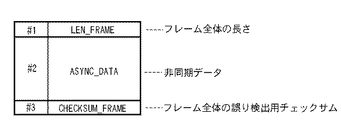
まず、7番目のフィールドとなるDATA_TYPEフィールドは、値としてASYNCを保持している。中継フレーム807を受信した各局は、このフィールドを参照することにより非同期データが送信されていることを識別できる。次に、8番目のフィールドとなるLEN_ASYNCフィールドは非同期データのデータ長を示す。同期データと異なり、一般に非同期データのデータ長は可変であることが多く、中継フレーム807を受信した各局はこのフィールドを参照することにより非同期データのデータ長を知ることができる。最後に、可変長となる9番目のフィールドとなるASYNC_DATAフィールドに非同期データが格納される。
First, the DATA_TYPE field, which is the seventh field, holds ASYNC as a value. Each station that has received the
ここでは、どのように従属局が非占有時間を用いて非同期データを送信するかを説明するものであり、このASYNC_DATAフィールドに対する詳細な内部フォーマットには特に言及しない。しかしながら、このASYNC_DATAフィールドの内部構成としては、非同期データの通信プロトコルに従って、例えば非同期データの宛先局のアドレスやデータ種別を識別するための各種タグなどを含むことが想定される。 Here, how the dependent station transmits asynchronous data using the non-occupancy time is described, and a detailed internal format for the ASYNC_DATA field is not particularly mentioned. However, the internal configuration of the ASYNC_DATA field is assumed to include various tags for identifying the address and data type of the destination station of the asynchronous data, for example, according to the asynchronous data communication protocol.
また、複数の宛先局に非同期データを伝送するために、ASYNC_DATAフィールドを複数のサブフィールドに分割することも可能である。このASYNC_DATAフィールドの内部に対してどのような使用方法を採用するにしても、本発明を適用することが可能であることは言うまでもない。 In addition, the ASYNC_DATA field can be divided into a plurality of subfields in order to transmit asynchronous data to a plurality of destination stations. It goes without saying that the present invention can be applied no matter what method of use is adopted for the inside of the ASYNC_DATA field.
次に、従属局103の動作を説明する。図8に示すように、従属局103はN+1番目のスーパーフレームにおいて中継フレーム808を送信する。この中継フレーム808のフレームフォーマットを図10に示す。このフレームフォーマットにおいて、1〜2番目のフィールドは図7に示すものと同じであり、従属局103はN+1番目の同報フレーム806に対する認識応答を送信する。
Next, the operation of the
ここで、従属局103が送信するべき非同期データを保持している場合、図10に示すように、非同期データ送信用のフィールドとして3〜5番目のフィールドが追加される。これらのフィールドは、図9に示す従属局102が送信する中継フレーム807における7〜9番目のフィールドにそれぞれ対応する。
Here, when the
従属局103はN+1番目のスーパーフレームにおいて中継伝送を行わないが、3〜5番目のフィールドを利用することにより、従属局102と同様に、非占有時間を利用して非同期データを伝送することが可能となる。
The
以上説明したように、従属局が認識応答を送信することによって通信帯域に非占有時間が設けられ、この非占有時間を利用して従属局が非同期データを送信できるようになる。その結果、新たに非同期データの転送が可能となり、同期データ及び非同期データの両方を含めた全体のデータ転送量を増大させるという効果が得られた。 As described above, when the dependent station transmits the recognition response, a non-occupancy time is provided in the communication band, and the dependent station can transmit asynchronous data using this non-occupied time. As a result, asynchronous data can be transferred anew, and the entire data transfer amount including both synchronous data and asynchronous data can be increased.
尚、一般に同期データは固定長として扱われることが多いため、固定長の同期データを用いて説明したが、可変長となる同期データに対しても本発明を適用することもできる。更に、認識応答の送信、同期データの中継伝送、非同期データの伝送を単一のフレームで送信するためのフォーマットを例示したが、これらを個別のフレームとして従属局から送信することも可能である。 In general, since synchronization data is often handled as a fixed length, the description has been given using the fixed-length synchronization data. However, the present invention can also be applied to synchronization data having a variable length. Furthermore, although the format for transmitting the recognition response, the relay transmission of the synchronous data, and the transmission of the asynchronous data in a single frame has been illustrated, it is also possible to transmit these from the subordinate station as individual frames.
[第二の実施形態]
次に、図面を参照しながら本発明に係る第二の実施形態を詳細に説明する。第一の実施形態では、本発明が適用された無線中継伝送システムにおいて、従属局が非同期データを送信することができることを説明した。この第二の実施形態では、制御局101が従属局102及び103と同様に、非同期データを送信する方法を説明する。
[Second Embodiment]
Next, a second embodiment according to the present invention will be described in detail with reference to the drawings. In the first embodiment, it has been described that a dependent station can transmit asynchronous data in a wireless relay transmission system to which the present invention is applied. In the second embodiment, a method in which the
第二の実施形態における無線中継伝送システムの構成は、図1を用いて説明した第一の実施形態の構成と同様であり、説明は省略する。また、制御局101及び従属局102〜105の内部構成も、図2及び図3を用いて説明した第一の実施形態の内部構成と同様であり、説明は省略する。
The configuration of the wireless relay transmission system in the second embodiment is the same as the configuration of the first embodiment described with reference to FIG. The internal configurations of the
第二の実施形態における中継伝送システムの動作例として、第一の実施形態で説明した図8に示すフレームを送信する場合を説明する。第一の実施形態で説明したように、従属局102〜105はN+1番目のスーパーフレームにおいて中継フレーム807〜810を送信することにより、中継伝送と非同期データの伝送を同時に実行している。
As an example of the operation of the relay transmission system in the second embodiment, a case of transmitting the frame shown in FIG. 8 described in the first embodiment will be described. As described in the first embodiment, the
図8に示すN+1番目のスーパーフレームでは、従属局103が中継フレーム808を送信しているが、中継フレーム808の終了時点から次のタイムスロットまで、まだ非占有時間が残されている。第二の実施形態では、この非占有時間に、制御局101が非同期データを保持した非同期フレームを送信する。
In the (N + 1) th superframe shown in FIG. 8, the
ここで、制御局101は図8に示す中継フレームを受信する。それぞれの中継フレームには、前述したようにLEN_FRAMEフィールドが含まれるため、制御局101はフレーム長判定部208がLEN_FRAMEフィールドの値を参照することで、当該中継フレームの長さを知ることができる。更に、制御局101はTDMAプロトコルを制御しているため、各タイムスロットの開始時点も既知である。
Here, the
従って、制御局101は各タイムスロットで送信される中継データの終了時点から次のタイムスロットまで通信メディアが利用されていない非占有時間を正確に検出することが可能である。
Therefore, the
図2において、送信タイミング生成部207は、フレーム長判定部208から受信フレーム終了時点、スーパーフレームタイミング生成部206から次タイムスロット開始時点に関する情報を得る。これらの情報に基づいて送信タイミング生成部207が送信フレーム生成部204に対してフレーム送信を指示する。このように、制御局101は、非占有時間において非同期フレームを送信することにより、他の従属局とのフレーム衝突を発生させることなく非同期データを伝送できる。
In FIG. 2, the transmission
図11は、制御局が非同期フレームを送信する場合のスーパーフレームの構成を示す図である。図11において、1101〜1110は第一の実施形態での図8に示す801〜810と同じフレームである。 FIG. 11 is a diagram illustrating a superframe configuration when the control station transmits an asynchronous frame. 11, 1101 to 1110 are the same frames as 801 to 810 shown in FIG. 8 in the first embodiment.
N+1番目のスーパーフレームにおいて、従属局103の中継フレーム1108を受信している制御局101は、中継フレーム1108の終了を検知し、直ちに非同期フレーム1111の送信を開始する。
In the (N + 1) th superframe, the
図12は、制御局が送信する非同期フレームの構成の一例を示す図である。この1番目のフィールドは非同期フレーム1111の全体の長さを示すLEN_FRAMEフィールドである。尚、LEN_FRAMEフィールドで示されるフレーム長の単位としては、実装に依存してバイト(8ビット)やワード(16ビット)などが挙げられるが、如何なる単位を採用しても本発明を適用することが可能である。
FIG. 12 is a diagram illustrating an example of a configuration of an asynchronous frame transmitted by the control station. This first field is a LEN_FRAME field indicating the entire length of the
制御局101は、この非同期フレーム1111が次のタイムスロットの開始時点よりも前に終了するように、非同期フレーム1111の長さを決定し、LEN_FRAMEフィールドを設定する。
The
図12に示す2番目のフィールドはASYNC_DATAフィールドであり、ここに制御局101から送信される非同期データが格納される。尚、第二の実施形態では、制御局101が非占有時間を用いてどのように非同期データを送信するかを説明するものであり、このASYNC_DATAフィールドに対する詳細な内部フォーマットには特に言及しない。しかしながら、このASYNC_DATAフィールド内部に対してどのような使用方法を採用するにしても、本発明を適用することが可能であることは言うまでもない。
The second field shown in FIG. 12 is an ASYNC_DATA field, in which asynchronous data transmitted from the
以上説明したように、従属局102〜105が非占有時間を利用して非同期データの送信を行った場合、制御局101も同様に非同期データを送信することができる。本発明を適用することにより、制御局及び従属局が同期データ及び非同期データの両方を送信することが可能となる。
As described above, when the
更に、通信状態に応じて、必要な中継伝送の回数を最適化し、非占有時間のほぼ全てを非同期データの伝送に利用できるため、システム全体のデータ転送量を増大させることができる。 Furthermore, since the number of necessary relay transmissions can be optimized according to the communication state and almost all of the non-occupancy time can be used for asynchronous data transmission, the data transfer amount of the entire system can be increased.
[第三の実施形態]
次に、図面を参照しながら本発明に係る第三の実施形態を詳細に説明する。第三の実施形態では、中継伝送を最適化するものである。
[Third embodiment]
Next, a third embodiment according to the present invention will be described in detail with reference to the drawings. In the third embodiment, relay transmission is optimized.
第三の実施形態における無線中継伝送システムの構成は、図1を用いて説明した第一の実施形態の構成と同様であり、説明は省略する。また、制御局101及び従属局102〜105の内部構成も、図2及び図3を用いて説明した第一の実施形態の内部構成と同様であり、説明は省略する。
The configuration of the wireless relay transmission system according to the third embodiment is the same as the configuration of the first embodiment described with reference to FIG. The internal configurations of the
第三の実施形態でも、N番目の同報フレーム401を従属局103及び104が受信に失敗した場合を想定する。この時、図13に示すように、受信した同報フレーム401中で3番目のフィールドに格納されている従属局104宛ての同期データであるISO_DATA3フィールドのみにビット誤りが発生していることもあり得る。
Also in the third embodiment, it is assumed that the
ここで、同報フレーム401全部が正しく受信できなくとも、従属局103にとってはISO_DATA2フィールドに格納されている自局宛ての同期データが取得できてさえいれば、以後の他の従属局からの中継伝送は不要である。それにもかかわらず、このような状態において、第一の実施形態では従属局102及び105は従属局103宛ての同期データを中継伝送しており、これらは無駄な通信として通信帯域を浪費することとなる。
Here, even if all the broadcast frames 401 cannot be received correctly, as long as the
第三の実施形態では、このような事態を鑑み、制御局101が送信する同報フレームのフォーマット例として図14に示すフォーマットを使用する。図14において、各従属局宛ての同期データはそれぞれISO_DATA1〜4フィールドに格納されている。更に、ISO_DATA1〜4フィールドの直後には、それぞれ同期データ毎に誤り検出符号によるチェックサムとしてCHECKSUM1〜4フィールドが備えられている。
In the third embodiment, in view of such a situation, the format shown in FIG. 14 is used as a format example of a broadcast frame transmitted by the
図15は、第三の実施形態におけるスーパーフレームの構成を示す図である。まず、N番目のスーパーフレームで制御局101が同報フレーム1501をブロードキャスト送信する。同報フレーム1501は図14に示すフレームフォーマットを持つ。同報フレーム1501を受信した従属局103は、各同期データに対するチェックサムであるCHECKSUM_ISO1〜4を検証する。その後、自局のタイムスロットで従属局103は中継フレーム1503を送信するが、第一の実施形態と同様に、中継フレーム1503にはACKNOWLEDGEフィールドが含まれている。
FIG. 15 is a diagram illustrating a configuration of a superframe in the third embodiment. First, the
ここで、ISO_DATA3のみにビット誤りが発生している場合、従属局103は自局宛ての同期データとなるISO_DATA2を正常に受信できているため、中継フレーム1503のACKNOWLEDGEフィールドには値ACKを設定する。そして、このACKNOWLEDGEフィールドを受信した他の従属局が従属局103に対してN番目の同報フレーム1501を中継伝送する必要がないことを認識する。
Here, when a bit error has occurred only in ISO_DATA3, the
このN番目の同報フレーム1501に対する中継伝送はN+1番目のスーパーフレームで実施され、従属局102は中継フレーム1507を、従属局105は中継フレーム1510を送信する。但し、従属局102及び105は、既に中継フレーム1503によって従属局103へ中継伝送する必要がないことを知っているため、中継フレーム1507及び1510には従属局103宛ての同期データは含まれない。
The relay transmission for the
従って、従属局102から送信される中継フレーム1507の長さは、図4に示す中継フレーム407よりも短くなる。また同様に、従属局105から送信される中継フレーム1510の長さも図4に示す中継フレーム410よりも短くなる。従って、N+1番目のスーパーフレームにおける非占有時間は図4に示す場合よりも長くなる。
Therefore, the length of the
以上のように、チェックサムと認識応答方式を改善することにより、中継伝送を最適化することが可能となり、より長い非占有時間を設けることができる。 As described above, by improving the checksum and the recognition response system, it becomes possible to optimize relay transmission and to provide a longer non-occupancy time.
また、制御局及び従属局は、第一及び第二の実施形態と同様の方式で、この非占有時間を利用して非同期データを送信する。これにより、中継伝送システムにおける同期データ及び非同期データ全体としてのデータ転送量を更に増大させることができる。 In addition, the control station and the dependent stations transmit asynchronous data using this non-occupancy time in the same manner as in the first and second embodiments. Thereby, the data transfer amount as the whole synchronous data and asynchronous data in a relay transmission system can further be increased.
以上説明した実施形態によれば、無線中継伝送システムにおいて受信局が正常にデータフレームを受信した場合に不必要となるデータ中継転送の回数を削減することが可能となる。従って、中継伝送に利用されなくなった通信時間を非同期データなど他のデータ転送のために使用することができるようになるため、ネットワーク全体としてのデータ転送量を増大させるという効果が得られる。 According to the embodiment described above, it is possible to reduce the number of data relay transfers that are unnecessary when a receiving station normally receives a data frame in a wireless relay transmission system. Therefore, since the communication time that is no longer used for relay transmission can be used for other data transfer such as asynchronous data, an effect of increasing the data transfer amount as a whole network can be obtained.
尚、本発明は複数の機器(例えば、ホストコンピュータ、インターフェース機器、リーダ、プリンタなど)から構成されるシステムに適用しても、1つの機器からなる装置(例えば、複写機、ファクシミリ装置など)に適用しても良い。 Even if the present invention is applied to a system constituted by a plurality of devices (for example, a host computer, an interface device, a reader, a printer, etc.), it is applied to an apparatus (for example, a copying machine, a facsimile machine, etc.) comprising a single device. It may be applied.
また、前述した実施形態の機能を実現するソフトウェアのプログラムコードを記録した記録媒体を、システム或いは装置に供給し、そのシステム或いは装置のコンピュータ(CPU若しくはMPU)が記録媒体に格納されたプログラムコードを読出し実行する。これによっても、本発明の目的が達成されることは言うまでもない。 In addition, a recording medium in which a program code of software for realizing the functions of the above-described embodiments is recorded is supplied to the system or apparatus, and the computer (CPU or MPU) of the system or apparatus stores the program code stored in the recording medium. Read and execute. It goes without saying that the object of the present invention can also be achieved by this.
この場合、コンピュータ読み取り可能な記録媒体から読出されたプログラムコード自体が前述した実施形態の機能を実現することになり、そのプログラムコードを記憶した記録媒体は本発明を構成することになる。 In this case, the program code itself read from the computer-readable recording medium realizes the functions of the above-described embodiments, and the recording medium storing the program code constitutes the present invention.
このプログラムコードを供給するための記録媒体として、例えばフレキシブルディスク、ハードディスク、光ディスク、光磁気ディスク、CD−ROM、CD−R、磁気テープ、不揮発性のメモリカード、ROMなどを用いることができる。 As a recording medium for supplying the program code, for example, a flexible disk, a hard disk, an optical disk, a magneto-optical disk, a CD-ROM, a CD-R, a magnetic tape, a nonvolatile memory card, a ROM, or the like can be used.
また、コンピュータが読出したプログラムコードを実行することにより、前述した実施形態の機能が実現されるだけでなく、次の場合も含まれることは言うまでもない。即ち、プログラムコードの指示に基づき、コンピュータ上で稼働しているOS(オペレーティングシステム)などが実際の処理の一部又は全部を行い、その処理により前述した実施形態の機能が実現される場合である。 In addition, by executing the program code read by the computer, not only the functions of the above-described embodiments are realized, but also the following cases are included. That is, based on the instruction of the program code, an OS (operating system) running on the computer performs part or all of the actual processing, and the functions of the above-described embodiments are realized by the processing. .
更に、記録媒体から読出されたプログラムコードがコンピュータに挿入された機能拡張ボードやコンピュータに接続された機能拡張ユニットに備わるメモリに書込む。その後、そのプログラムコードの指示に基づき、その機能拡張ボードや機能拡張ユニットに備わるCPUなどが実際の処理の一部又は全部を行い、その処理により前述した実施形態の機能が実現される場合も含まれることは言うまでもない。 Further, the program code read from the recording medium is written in a memory provided in a function expansion board inserted into the computer or a function expansion unit connected to the computer. After that, based on the instruction of the program code, the CPU of the function expansion board or function expansion unit performs part or all of the actual processing, and the function of the above-described embodiment is realized by the processing. Needless to say.
101 制御局
102 従属局
103 従属局
104 従属局
105 従属局
Claims (10)
前記複数の従属局のそれぞれは、
N(Nは整数)番目のスーパーフレームにおいて前記制御局からブロードキャスト送信されたデータを受信する手段と、
N番目のスーパーフレーム内の自局に割当てられたタイムスロットにおいて、前記データの受信状況を示す認識応答を送信する手段と、
他の従属局から送信される前記認識応答に応じて、当該他の従属局宛てのデータをN+1番目のスーパーフレーム内の自局に割当てられたタイムスロットにおいて中継伝送する手段とを有することを特徴とする通信システム。 Control station is a communication system that broadcasts a data dependent station addressed several per superframe,
Each of the plurality of dependent stations is
Means for receiving data broadcast from the control station in an Nth (N is an integer) superframe;
Means for transmitting a recognition response indicating the reception status of the data in a time slot allocated to the own station in the Nth superframe;
Means for relaying and transmitting data addressed to the other dependent station in a time slot assigned to the own station in the N + 1th superframe in response to the recognition response transmitted from the other dependent station. A communication system.
前記検出された期間に他のデータを送信することを特徴とする請求項1乃至4の何れか1項に記載の通信システム。 The control station further includes means for detecting a period that is not used among periods reserved for relay transmission of data addressed to the other dependent stations by each of the plurality of dependent stations,
Communication system according to any one of claims 1 to 4, characterized in that to transmit other data on the detected period.
N(Nは整数)番目のスーパーフレームにおいて前記制御局からブロードキャスト送信されたデータを受信する手段と、
N番目のスーパーフレーム内の自局に割当てられたタイムスロットにおいて、前記データの受信状況を示す認識応答を送信する手段と、
他の従属局から送信される前記認識応答に応じて、当該他の従属局宛てのデータをN+1番目のスーパーフレーム内の自局に割当てられたタイムスロットにおいて中継伝送する手段とを有することを特徴とする通信システムの従属局。 Control station is a subordinate station of a communication system broadcasts data of the dependent station addressed several per superframe,
Means for receiving data broadcast from the control station in an Nth (N is an integer) superframe;
Means for transmitting a recognition response indicating the reception status of the data in a time slot allocated to the own station in the Nth superframe;
Means for relaying and transmitting data addressed to the other dependent station in a time slot assigned to the own station in the N + 1th superframe in response to the recognition response transmitted from the other dependent station. Dependent station of the communication system.
受信する手段が、N(Nは整数)番目のスーパーフレームにおいて前記制御局からブロードキャスト送信されたデータを受信する工程と、
送信する手段が、N番目のスーパーフレーム内の自局に割当てられたタイムスロットにおいて、前記データの受信状況を示す認識応答を送信する工程と、
中継伝送する手段が、他の従属局から送信される前記認識応答に応じて、当該他の従属局宛てのデータをN+1番目のスーパーフレーム内の自局に割当てられたタイムスロットにおいて中継伝送する工程とを有することを特徴とする通信システムにおける従属局の中継伝送方法。 Control station is a relay transmission method of the dependent station in a communication system broadcasts data of the dependent station addressed several per superframe,
Means for receiving data broadcast from the control station in an Nth (N is an integer) superframe;
Means for transmitting a recognition response indicating a reception status of the data in a time slot allocated to the local station in the Nth superframe;
A step of relaying and transmitting data addressed to the other dependent station in a time slot allocated to the own station in the N + 1th superframe, in accordance with the recognition response transmitted from the other dependent station. A relay transmission method of a dependent station in a communication system.
Priority Applications (5)
| Application Number | Priority Date | Filing Date | Title |
|---|---|---|---|
| JP2008220501A JP5185024B2 (en) | 2008-08-28 | 2008-08-28 | Communication system, its dependent stations, and relay transmission method |
| CN200980133921.2A CN102138295B (en) | 2008-08-28 | 2009-07-17 | Communication system, dependent station thereof and dependent-station relay transmission method |
| US12/999,720 US8848595B2 (en) | 2008-08-28 | 2009-07-17 | Communication system, dependent station thereof and dependent-station relay transmission method |
| EP20090787998 EP2342857B1 (en) | 2008-08-28 | 2009-07-17 | Communication system, dependent station thereof and dependent-station relay transmission method |
| PCT/JP2009/063299 WO2010024073A1 (en) | 2008-08-28 | 2009-07-17 | Communication system, dependent station thereof and dependent-station relay transmission method |
Applications Claiming Priority (1)
| Application Number | Priority Date | Filing Date | Title |
|---|---|---|---|
| JP2008220501A JP5185024B2 (en) | 2008-08-28 | 2008-08-28 | Communication system, its dependent stations, and relay transmission method |
Related Child Applications (1)
| Application Number | Title | Priority Date | Filing Date |
|---|---|---|---|
| JP2013004042A Division JP5362131B2 (en) | 2013-01-11 | 2013-01-11 | COMMUNICATION DEVICE, COMMUNICATION DEVICE CONTROL METHOD, AND PROGRAM |
Publications (3)
| Publication Number | Publication Date |
|---|---|
| JP2010056963A JP2010056963A (en) | 2010-03-11 |
| JP2010056963A5 JP2010056963A5 (en) | 2011-09-29 |
| JP5185024B2 true JP5185024B2 (en) | 2013-04-17 |
Family
ID=41308701
Family Applications (1)
| Application Number | Title | Priority Date | Filing Date |
|---|---|---|---|
| JP2008220501A Expired - Fee Related JP5185024B2 (en) | 2008-08-28 | 2008-08-28 | Communication system, its dependent stations, and relay transmission method |
Country Status (5)
| Country | Link |
|---|---|
| US (1) | US8848595B2 (en) |
| EP (1) | EP2342857B1 (en) |
| JP (1) | JP5185024B2 (en) |
| CN (1) | CN102138295B (en) |
| WO (1) | WO2010024073A1 (en) |
Families Citing this family (5)
| Publication number | Priority date | Publication date | Assignee | Title |
|---|---|---|---|---|
| US8953516B2 (en) * | 2010-03-04 | 2015-02-10 | The Chamberlain Group, Inc. | Facilitating asynchronous transmissions using a protocol having asynchronous and synchronous portions |
| JP5676911B2 (en) * | 2010-04-30 | 2015-02-25 | キヤノン株式会社 | COMMUNICATION SYSTEM, CONTROL NODE DEVICE, ITS CONTROL METHOD, CONTROLLED NODE DEVICE, ITS CONTROL METHOD, PROGRAM |
| JP5327204B2 (en) * | 2010-11-19 | 2013-10-30 | 株式会社デンソー | Wireless communication apparatus and wireless communication system |
| CN102231642B (en) * | 2011-06-29 | 2013-02-13 | 绥中时骏科技有限公司 | Time division-synchronous code division multiple access (TD-SCDMA) synchronous transmission and recovery device |
| JP5997974B2 (en) * | 2012-08-16 | 2016-09-28 | 日本放送協会 | Wireless communication apparatus and program |
Family Cites Families (66)
| Publication number | Priority date | Publication date | Assignee | Title |
|---|---|---|---|---|
| JPS61210745A (en) | 1985-03-14 | 1986-09-18 | Nec Corp | Broadcast communication system |
| JPH06188676A (en) * | 1992-12-17 | 1994-07-08 | Canon Inc | Correlator |
| JPH06188675A (en) * | 1992-12-18 | 1994-07-08 | Canon Inc | Surface acoustic wave convolver |
| US5677909A (en) * | 1994-05-11 | 1997-10-14 | Spectrix Corporation | Apparatus for exchanging data between a central station and a plurality of wireless remote stations on a time divided commnication channel |
| JP3136076B2 (en) * | 1994-06-08 | 2001-02-19 | キヤノン株式会社 | Code division multiplex modem |
| JPH0897675A (en) * | 1994-09-28 | 1996-04-12 | Canon Inc | Surface acoustic wave element and its manufacture and communication equipment using it |
| US5917850A (en) * | 1994-11-24 | 1999-06-29 | Canon Kabushiki Kaisha | Spread spectrum receiving apparatus |
| JP3395414B2 (en) | 1994-12-07 | 2003-04-14 | 株式会社明電舎 | Delivery confirmation method for broadcast transmission |
| JPH0998061A (en) * | 1995-07-24 | 1997-04-08 | Canon Inc | Saw matched filter, receiving device using the filter and communication system |
| JPH09153754A (en) * | 1995-09-27 | 1997-06-10 | Canon Inc | Saw(surface accoustic wave) converter, saw convolver receiver and communication system using the converter |
| US6298405B1 (en) * | 1997-02-14 | 2001-10-02 | Canon Kabushiki Kaisha | Data communication system, printing system and data communication apparatus |
| US6625162B2 (en) * | 1997-12-17 | 2003-09-23 | Canon Kabushiki Kaisha | Method and apparatus for data transmission with control over access to a transmission medium |
| JP3414244B2 (en) * | 1998-02-27 | 2003-06-09 | ソニー株式会社 | Communication control method and transmission device |
| JP3007069B2 (en) | 1998-03-05 | 2000-02-07 | 日本電信電話株式会社 | Wireless packet transfer method |
| JPH11289335A (en) | 1998-04-02 | 1999-10-19 | Mitsubishi Electric Corp | Data transmitting device |
| JP2000059459A (en) * | 1998-08-11 | 2000-02-25 | Canon Inc | Data communication device, data communication system, data communication method, and storage medium |
| JP2000092076A (en) * | 1998-09-11 | 2000-03-31 | Sony Corp | Communication control method and transmitter |
| US7936381B2 (en) * | 1998-10-30 | 2011-05-03 | Canon Kabushiki Kaisha | Management and setting of photographing condition of image sensing apparatus |
| JP4374725B2 (en) * | 1999-09-22 | 2009-12-02 | パナソニック株式会社 | Communication method and communication station |
| US6724770B1 (en) | 2000-02-17 | 2004-04-20 | Kenneth P. Birman | Multicast protocol with reduced buffering requirements |
| US6788670B1 (en) * | 2000-10-27 | 2004-09-07 | Telefonaktiebolaget Lm Ericsson (Publ) | Method for forwarding in multi-hop networks |
| CA2376987C (en) * | 2001-03-16 | 2005-07-26 | Nippon Telegraph And Telephone Corporation | Wireless communication system using access points that can be freely set up by users |
| US7594010B2 (en) * | 2001-06-28 | 2009-09-22 | King's London College | Virtual antenna array |
| US7224942B2 (en) * | 2001-07-26 | 2007-05-29 | Telefonaktiebolaget Lm Ericsson (Publ) | Communications system employing non-polluting pilot codes |
| JP2005538574A (en) * | 2001-10-03 | 2005-12-15 | エクストリームスペクトラム,インコーポレイテッド | How the media access controller works |
| US7027409B2 (en) * | 2002-01-10 | 2006-04-11 | Harris Corporation | Method and device for establishing communication links and for estimating overall quality of a directional link and reporting to OLSR in a communication system |
| US7672274B2 (en) * | 2002-01-11 | 2010-03-02 | Broadcom Corporation | Mobility support via routing |
| US7095732B1 (en) * | 2002-04-12 | 2006-08-22 | Bbn Technologies Corp. | Quality of service based media access control for mobile ad hoc networks |
| JP2004023454A (en) * | 2002-06-17 | 2004-01-22 | Canon Inc | Radio communication system and radio communication method thereof |
| US7894381B2 (en) * | 2003-03-04 | 2011-02-22 | Samsung Electronics Co., Ltd. | System and method of reliably broadcasting data packet under ad-hoc network environment |
| KR100490429B1 (en) * | 2003-04-25 | 2005-05-17 | 삼성전자주식회사 | System and method for managing the association of device to a piconet |
| CN101472342B (en) * | 2003-05-16 | 2012-02-22 | 松下电器产业株式会社 | Medium access control in master-slave system |
| KR100547116B1 (en) * | 2003-05-23 | 2006-01-26 | 삼성전자주식회사 | Method for communicating through wireless network and a device thereof |
| GB0407902D0 (en) * | 2003-08-15 | 2004-05-12 | Koninkl Philips Electronics Nv | Feedback signalling for multicast data transmission |
| KR100643272B1 (en) * | 2004-04-26 | 2006-11-10 | 삼성전자주식회사 | Method and apparatus for communication between coordinator-based wireless networks |
| JP2005333360A (en) * | 2004-05-19 | 2005-12-02 | Sony Corp | System and method for radio communication and device |
| JP4271089B2 (en) * | 2004-06-17 | 2009-06-03 | パナソニック株式会社 | Wireless communication method and wireless communication apparatus |
| JP4379237B2 (en) * | 2004-07-14 | 2009-12-09 | ソニー株式会社 | Wireless communication system, wireless communication apparatus, wireless communication method, and computer program |
| CA2576833C (en) | 2004-08-12 | 2014-10-28 | Interdigital Technology Corporation | Method and system for controlling access to a wireless communication medium |
| CN101036345A (en) * | 2004-09-29 | 2007-09-12 | 皇家飞利浦电子股份有限公司 | Interconnection of wireless networks using a master/slave node |
| CN1943175B (en) * | 2005-02-04 | 2011-07-27 | 株式会社东芝 | Optimal channel assignment for multi-class, multi-channel wireless LANs and the like |
| JP4763334B2 (en) * | 2005-04-28 | 2011-08-31 | ルネサスエレクトロニクス株式会社 | Wireless ad hoc communication system and communication terminal synchronization method in wireless ad hoc communication system |
| JP2006319676A (en) * | 2005-05-12 | 2006-11-24 | Oki Electric Ind Co Ltd | Frame transmitting method, topology acquiring method and radio communication system |
| CN101238687B (en) * | 2005-08-04 | 2011-12-21 | 皇家飞利浦电子股份有限公司 | Method, device and system for coexistence of wireless technology for facilitating competing identical bandwidth |
| KR100943601B1 (en) * | 2005-12-27 | 2010-02-24 | 삼성전자주식회사 | Method and system for selecting relay station in communication using multihop relay scheme |
| US8363675B2 (en) * | 2006-03-24 | 2013-01-29 | Samsung Electronics Co., Ltd. | Method and system for transmission of uncompressed video over wireless communication channels |
| JP2007266876A (en) | 2006-03-28 | 2007-10-11 | Toyota Infotechnology Center Co Ltd | Wireless communication method, wireless communication device, and wireless communication program |
| US7813373B2 (en) * | 2006-05-25 | 2010-10-12 | Motorola, Inc. | Systems, methods and apparatus for detecting time slot interference and recovering from time slot interference in an ad hoc wireless communication network |
| KR100871853B1 (en) * | 2006-06-05 | 2008-12-03 | 삼성전자주식회사 | Data slot allocation method for transferring uncompressed AV data, uncompressed AV data transferring method, and apparatus thereof |
| KR100871854B1 (en) * | 2006-06-05 | 2008-12-03 | 삼성전자주식회사 | Channel allocation management method for transferring asynchronous data, asynchronous data transferring method, and apparatus thereof |
| JP4790544B2 (en) * | 2006-08-31 | 2011-10-12 | 富士通株式会社 | Retransmission control method and relay station apparatus in relay communication system |
| JP4961910B2 (en) * | 2006-09-01 | 2012-06-27 | ソニー株式会社 | Wireless communication apparatus and wireless communication system |
| JP4865456B2 (en) * | 2006-09-01 | 2012-02-01 | キヤノン株式会社 | Communication device, control method for controlling communication device, program for controlling communication device, and storage medium storing program |
| JP4138831B2 (en) * | 2006-09-19 | 2008-08-27 | 株式会社東芝 | Wireless communication apparatus and program |
| DE602006006917D1 (en) * | 2006-11-20 | 2009-07-02 | Ntt Docomo Inc | Relay for forwarding a data packet sent from a first transmitter / receiver to a second transmitter / receiver. |
| JP5072329B2 (en) * | 2006-11-22 | 2012-11-14 | キヤノン株式会社 | Control device and control method thereof, communication device and control method thereof, wireless communication system, and program |
| US8457260B2 (en) * | 2006-12-04 | 2013-06-04 | Qualcomm Incorporated | System and method for acquisition in wireless communication systems |
| JP5008427B2 (en) | 2007-03-09 | 2012-08-22 | ホシザキ電機株式会社 | Dishwasher |
| JP2008227642A (en) * | 2007-03-09 | 2008-09-25 | Hitachi Ltd | Retransmission control method and radio communication system |
| US8451809B2 (en) * | 2007-04-13 | 2013-05-28 | Hart Communication Foundation | Wireless gateway in a process control environment supporting a wireless communication protocol |
| JP2008306549A (en) * | 2007-06-08 | 2008-12-18 | Canon Inc | Method for controlling wireless control station and wireless terminal station, and computer program for computer to implement the control method |
| JP4989346B2 (en) * | 2007-07-30 | 2012-08-01 | キヤノン株式会社 | COMMUNICATION SYSTEM, COMMUNICATION DEVICE, AND COMMUNICATION METHOD |
| US8331308B1 (en) * | 2007-11-09 | 2012-12-11 | Research In Motion Limited | Systems and methods for network MIMO |
| TWI458284B (en) * | 2007-12-07 | 2014-10-21 | Koninkl Philips Electronics Nv | Multiple channel support in distributed wireless systems |
| JP2009253382A (en) * | 2008-04-01 | 2009-10-29 | Canon Inc | Terminal station, method, program, and system thereof |
| JP5184945B2 (en) * | 2008-04-07 | 2013-04-17 | キヤノン株式会社 | Wireless communication system, terminal station, wireless communication method, program, and storage medium |
-
2008
- 2008-08-28 JP JP2008220501A patent/JP5185024B2/en not_active Expired - Fee Related
-
2009
- 2009-07-17 EP EP20090787998 patent/EP2342857B1/en active Active
- 2009-07-17 US US12/999,720 patent/US8848595B2/en active Active
- 2009-07-17 CN CN200980133921.2A patent/CN102138295B/en active Active
- 2009-07-17 WO PCT/JP2009/063299 patent/WO2010024073A1/en active Application Filing
Also Published As
| Publication number | Publication date |
|---|---|
| JP2010056963A (en) | 2010-03-11 |
| US20110096716A1 (en) | 2011-04-28 |
| CN102138295A (en) | 2011-07-27 |
| WO2010024073A1 (en) | 2010-03-04 |
| EP2342857A1 (en) | 2011-07-13 |
| CN102138295B (en) | 2014-03-12 |
| US8848595B2 (en) | 2014-09-30 |
| EP2342857B1 (en) | 2012-07-11 |
Similar Documents
| Publication | Publication Date | Title |
|---|---|---|
| US7561542B2 (en) | System, method and apparatus for determining if data from a source has arrived properly at a destination in a time division multiplex (TDM) communication network | |
| JP5192498B2 (en) | System and method for wireless communication of uncompressed video with multiple object sets (MDA) | |
| KR100750166B1 (en) | Method and apparatus for transmitting Data efficiently in wireless network system | |
| JP3891145B2 (en) | Wireless communication apparatus, wireless communication method and program | |
| US7003710B2 (en) | Communications method, communications apparatus and communications system using same communications apparatus | |
| JP5185024B2 (en) | Communication system, its dependent stations, and relay transmission method | |
| KR20070051632A (en) | Method and apparatus for transmitting data frame efficiently in communication network | |
| US11962413B2 (en) | Wireless communication device and method | |
| US11909525B2 (en) | Communication system, communication method, and communication apparatus | |
| US20110200130A1 (en) | Method and apparatus for transmitting/receiving data in mu-mimo system | |
| EP2165431B1 (en) | Data transmission system for asynchronous transmitting data and map information | |
| KR20070087725A (en) | Method for effectively transmitting or receiving data via wireless network, and wireless device thereof | |
| US8780737B2 (en) | Apparatus and method for loop-back in wireless communication systems | |
| JP5362131B2 (en) | COMMUNICATION DEVICE, COMMUNICATION DEVICE CONTROL METHOD, AND PROGRAM | |
| JP2007074641A (en) | Communication system | |
| JP4479208B2 (en) | Wireless relay method and apparatus, and wireless relay system | |
| JP6813858B2 (en) | Wireless communication system, wireless communication terminal, collision detection method, program | |
| JP2002135273A (en) | Method and equipment for radio transmission | |
| JP2007325077A (en) | Data receiver and data receiving method | |
| JP2009232084A (en) | Communication system, data transmission side device, data reception side device, and automatic retransmission request resetting method |
Legal Events
| Date | Code | Title | Description |
|---|---|---|---|
| A521 | Written amendment |
Free format text: JAPANESE INTERMEDIATE CODE: A523 Effective date: 20110812 |
|
| A621 | Written request for application examination |
Free format text: JAPANESE INTERMEDIATE CODE: A621 Effective date: 20110812 |
|
| TRDD | Decision of grant or rejection written | ||
| A01 | Written decision to grant a patent or to grant a registration (utility model) |
Free format text: JAPANESE INTERMEDIATE CODE: A01 Effective date: 20121221 |
|
| A61 | First payment of annual fees (during grant procedure) |
Free format text: JAPANESE INTERMEDIATE CODE: A61 Effective date: 20130117 |
|
| R151 | Written notification of patent or utility model registration |
Ref document number: 5185024 Country of ref document: JP Free format text: JAPANESE INTERMEDIATE CODE: R151 |
|
| FPAY | Renewal fee payment (event date is renewal date of database) |
Free format text: PAYMENT UNTIL: 20160125 Year of fee payment: 3 |
|
| LAPS | Cancellation because of no payment of annual fees |