JP5179556B2 - Tap holder - Google Patents
Tap holder Download PDFInfo
- Publication number
- JP5179556B2 JP5179556B2 JP2010239285A JP2010239285A JP5179556B2 JP 5179556 B2 JP5179556 B2 JP 5179556B2 JP 2010239285 A JP2010239285 A JP 2010239285A JP 2010239285 A JP2010239285 A JP 2010239285A JP 5179556 B2 JP5179556 B2 JP 5179556B2
- Authority
- JP
- Japan
- Prior art keywords
- tap
- tap holder
- rear end
- shank member
- main body
- Prior art date
- Legal status (The legal status is an assumption and is not a legal conclusion. Google has not performed a legal analysis and makes no representation as to the accuracy of the status listed.)
- Active
Links
Images
Landscapes
- Gripping On Spindles (AREA)
Description
本発明は、工作機械の主軸に取り付けられる工具ホルダに、タップを取り付け固定するタップホルダないしタップコレットに関する。 The present invention relates to a tap holder or a tap collet that attaches and fixes a tap to a tool holder attached to a spindle of a machine tool.
金属製のワークに雌ねじ孔を設けるタップ加工にあっては、タップを回転させながらワークの孔に進行(送り)させて孔壁にねじ山を形成する。最も良好な雌ねじ孔を形成するために、タップの回転および進行(送り)は、タップのピッチに合わせて同期しなければならない。そこでNC装置において、主軸の回転と主軸の送りを同期させる同期制御を行う。ところが、かかる同期制御において、なんらかの原因により工作機械の主軸の回転と送り前進とが同期せず不一致になると、ねじ山の稜線が削れて雌ねじ孔の口径が大きくなったり、ねじ山が痩せたりするなどの不都合が生じる。特に、工作機械および工作物が大型化すれば、同期が若干量くずれ、タップの進行が遅れる懸念があった。 In the tapping process in which the female screw hole is provided in the metal work, the thread is formed in the hole wall by advancing (feeding) the work hole while rotating the tap. In order to form the best female thread hole, the rotation and progression (feed) of the taps must be synchronized to the tap pitch. Therefore, in the NC device, synchronous control is performed to synchronize the rotation of the spindle and the feed of the spindle. However, in such synchronous control, if the rotation of the spindle of the machine tool and the feed forward are not synchronized due to some cause and they do not match, the ridgeline of the screw thread is shaved and the diameter of the female screw hole is increased or the thread is thinned. Inconvenience such as occurs. In particular, when the machine tool and the workpiece are increased in size, there is a concern that the synchronization is slightly shifted and the progress of the tap is delayed.
そこで、主軸の回転と軸送りとの同期誤差を吸収する技術としては従来、例えば、特開2008−12613号公報(特許文献1)に記載のごときタップホルダが知られている。特許文献1に記載のタップホルダは、一端にタップを保持するタップコレットと、このタップコレットを受け入れて回転不能に把持固定するタッパー本体とからなる。タッパー本体の透孔内には、弾性変形可能な樹脂製ボールがほとんど隙間のない状態で保持されている。そして、樹脂製ボールはタップコレットの凹溝内に突出し、凹溝に密着するよう押圧する。これによりタップコレットはタッパー本体と結合して、軸方向の移動が規制される。 Therefore, as a technique for absorbing the synchronization error between the rotation of the main shaft and the shaft feed, a tap holder as described in, for example, Japanese Patent Application Laid-Open No. 2008-12613 (Patent Document 1) is conventionally known. The tap holder described in Patent Document 1 includes a tap collet that holds a tap at one end, and a tapper body that receives the tap collet and holds and fixes it in a non-rotatable manner. In the through hole of the tapper main body, an elastically deformable resin ball is held with almost no gap. Then, the resin ball protrudes into the groove of the tap collet and is pressed so as to be in close contact with the groove. As a result, the tap collet is coupled to the tapper body, and movement in the axial direction is restricted.
また、タップコレットの他端には軸直角方向に延在する回り止め溝が形成されており、この回り止め溝にタッパー本体のピンが係合して、タッパー本体の回転運動をタップコレットへ伝達する。 Also, the other end of the tap collet is formed with a detent groove extending in the direction perpendicular to the axis, and the pin of the tapper body is engaged with this detent groove to transmit the rotational movement of the tapper body to the tap collet. To do.
樹脂製ボールはタッパー本体の軸移動をタップコレットに正確に伝達するので、特許文献1のタップホルダは同期してタップ加工を行うことができる。かかるタップ加工において、主軸の回転と軸送りの誤差などにより、タップコレットが引っ張り力によって軸先端のタップ側方向に移動しようとする場合、透孔内においてほとんど隙間のない状態で保持されている樹脂製ボールは、透孔の孔壁と凹部の表面とによって軸方向のせん断応力を受けて弾性変形し、その分タップコレットの軸方向への微小量の移動を許容する。この結果、軸送りの誤差を吸収するようタップコレットがタップのピッチに一致する方向に微小移動し、精度の高いタップ加工を行うことができるというものである。 Since the resin balls accurately transmit the axial movement of the tapper body to the tap collet, the tap holder of Patent Document 1 can perform tapping in synchronization. In such tap processing, when the tap collet tries to move in the tap side direction of the shaft tip due to pulling force due to rotation of the main shaft and shaft feed, etc., the resin that is held in the through hole with almost no gap The ball-made ball is elastically deformed by the axial shear stress due to the hole wall of the through hole and the surface of the recess, and allows a small amount of movement of the tap collet in the axial direction. As a result, the tap collet moves slightly in the direction matching the pitch of the tap so as to absorb the axial feed error, and the tap processing with high accuracy can be performed.
しかし、上記従来のようなタップホルダにあっては、以下に説明するような問題を生ずる。つまり、樹脂製ボールの弾性変形は極めて微小であることから、吸収することができる誤差範囲が小さかった。このため、大型化したタップ加工にあっては、誤差を吸収することができない。また、樹脂製ボールがタップコレットに嵌合するため、タップコレットはタッパー本体に固定されており、吸収できる誤差に限界があった。 However, the conventional tap holder causes problems as described below. That is, since the elastic deformation of the resin balls is extremely small, the error range that can be absorbed is small. For this reason, the error cannot be absorbed in the tapping process which is enlarged. Further, since the resin balls are fitted to the tap collet, the tap collet is fixed to the tapper body, and there is a limit to the error that can be absorbed.
本発明は、上述の実情に鑑み、大きな誤差量であっても吸収することができるタップホルダを提供することを目的とする。 An object of this invention is to provide the tap holder which can absorb even if it is a big error amount in view of the above-mentioned situation.
この目的のため第1発明によるタップホルダは、略円筒形状であって軸線に沿って延びる中心孔を有し、工具ホルダにチャッキングされるためのシャンク部材と、軸線方向後端領域が外径一定のストレート形状にされ、軸線方向先端部にタップを把持するための把持部を有し、後端領域がシャンク部材の中心孔に挿通されることによりシャンク部材に前進および後退可能に支持されるタップホルダ本体と、シャンク部材とタップホルダ本体との間の第1の位置に設けられて基準位置よりも軸線方向後端側へ後退したタップホルダ本体を軸線方向先端側に付勢するコンプレッション用弾性部材と、シャンク部材とタップホルダ本体との間の第2の位置に設けられて基準位置よりも軸線方向先端側へ前進したタップホルダ本体を軸線方向後端側に付勢するテンション用弾性部材とを備える。そして、シャンク部材の中心孔の内周面は、相対的に大きな内径の部分と、相対的に小さな内径の部分であって後端領域の外周面に緊密に接触してタップの芯をシャンク部材の軸線に一致させるガイド部とを含む。 For this purpose, the tap holder according to the first invention has a substantially cylindrical shape and has a center hole extending along the axis , the shank member to be chucked by the tool holder, and the axial rear end region having an outer diameter. is a constant straight shape, have a grip portion for gripping the tap axially forward end portion, is advanced and retracted rotatably supported to the shank member by the rear end region is inserted through the center hole of the shank member Elasticity for compression that urges the tap holder main body and the tap holder main body, which is provided at the first position between the shank member and the tap holder main body and retracted from the reference position toward the rear end in the axial direction, toward the front end in the axial direction. The tap holder main body which is provided at the second position between the member and the shank member and the tap holder main body and has advanced to the front end side in the axial direction from the reference position is set to the rear end side in the axial direction. And a tension elastic member for energizing. And the inner peripheral surface of the center hole of the shank member is a relatively large inner diameter portion and a relatively small inner diameter portion that is in close contact with the outer peripheral surface of the rear end region, and the core of the tap is the shank member. to coincide with the axis and a guide portion.
かかる本発明によれば、後退したタップホルダ本体を基準位置へ復帰するよう軸線方向先端側に付勢するコンプレッション用弾性部材と、前進したタップホルダ本体を基準位置へ復帰するよう軸線方向後端側に付勢するテンション用弾性部材をそれぞれ備えることから、樹脂ボールがコンプレッション用弾性部材およびテンション用弾性部材を兼用する構成の従来技術と比較して、主軸の回転と軸送りの誤差を好適に吸収することができる。しかも、ガイド部を有することから、タップホルダ本体は、ガイド部を有さない従来技術よりも大きな距離を相対移動することができる。したがって、主軸の回転と軸送りの誤差が大きい場合であっても、誤差を十分に吸収して回転と軸送りとを同期させることができる。この結果、大型化したタップ加工にも適用することができる。 According to the present invention, the compression elastic member that urges the retracted tap holder body toward the axial front end side to return to the reference position, and the axial rear end side to return the advanced tap holder body to the reference position. Since each of the tension elastic members urged against each other is provided, the resin ball absorbs errors in the rotation of the main shaft and the shaft feed more favorably than the conventional technology in which the resin ball serves as both the compression elastic member and the tension elastic member. can do. And since it has a guide part, a tap holder main body can be relatively moved the larger distance than the prior art which does not have a guide part. Therefore, even when the error between the rotation of the main shaft and the shaft feed is large, the error can be sufficiently absorbed and the rotation and the shaft feed can be synchronized. As a result, the present invention can also be applied to an enlarged tap process.
本発明は、シャンク部材をタップホルダ本体よりも軸線方向先端側に配置することを排除するものではない。また、本発明のタップホルダがコレットないしタップコレットとして利用されて工具ホルダにチャッキングされることを排除するものではない。本発明のガイド部は、特に限定されるものではなく、軸線の周りに周方向所定間隔で配置されて軸線方向に延びる軌道のようなものであってもよい。例えば、シャンク部材が有するガイド部はシリンダ形状であり、ピストン形状のタップホルダ本体を軸線方向に案内してもよい。あるいは、タップホルダ本体が有するガイド部はピストン形状であり、シリンダ形状のシャンク部材に軸線方向に案内されてもよい。第2発明によるタップホルダは、工具ホルダにチャッキングされるためのシャンク部材と、シャンク部材に前進および後退可能に支持され、タップを軸線方向先端側で把持するための把持部を有するタップホルダ本体と、シャンク部材とタップホルダ本体との間の第1の位置に設けられて基準位置よりも軸線方向後端側へ後退したタップホルダ本体を軸線方向先端側に付勢するコンプレッション用弾性部材と、シャンク部材とタップホルダ本体との間の第2の位置に設けられて基準位置よりも軸線方向先端側へ前進したタップホルダ本体を軸線方向後端側に付勢するテンション用弾性部材とを備え、シャンク部材は、略円筒形状であって、軸線に沿って後端から先端側に向かって延びる中心孔と、軸線に沿って先端から後端に向かって延び中心孔と接続するタップ挿入孔とが形成され、中心孔にタップホルダ本体の先端領域を受け入れてタップホルダ本体を軸線方向に案内し、タップホルダ本体は、中心孔の内周面と摺接する先端領域の先端部外周面に、タップの芯をシャンク部材の軸線に一致させるガイド部を有する。 The present invention does not exclude the arrangement of the shank member closer to the tip end side in the axial direction than the tap holder body. Moreover, it does not exclude that the tap holder of the present invention is used as a collet or a tap collet and is chucked to the tool holder. The guide portion of the present invention is not particularly limited, and may be a track that is arranged around the axis at predetermined intervals in the circumferential direction and extends in the axial direction. For example, the guide portion of the shank member may be a cylinder shape, and the piston-shaped tap holder body may be guided in the axial direction. Or the guide part which a tap holder main body has is a piston shape, and may be guided to an axial direction by a cylinder-shaped shank member. A tap holder according to a second aspect of the present invention is a tap holder main body having a shank member to be chucked by a tool holder, a gripping portion supported by the shank member so as to be able to advance and retreat, and for gripping the tap on the tip end side in the axial direction. And an elastic member for compression that is provided at a first position between the shank member and the tap holder main body and biases the tap holder main body retracted toward the rear end side in the axial direction from the reference position toward the front end side in the axial direction. A tension elastic member provided at a second position between the shank member and the tap holder main body and biasing the tap holder main body that has advanced from the reference position toward the front end side in the axial direction toward the rear end side in the axial direction; The shank member is substantially cylindrical and has a center hole extending from the rear end toward the front end side along the axis, and a center hole extending from the front end toward the rear end along the axis. It is formed and the tap insert holes for connecting the holes to guide the tap holder body axially accepts distal region of the tap holder body into the center hole, the tap holder body, the inner circumferential surface of the central hole and slidably contacting the tip region to the tip outer peripheral surface, that having a guide portion for matching the cores of the tap to the axis of the shank member.
好ましい実施形態として、第1発明のガイド部は、後端領域の外周面と摺接する中心孔の先端部内周面である。 As a preferred embodiment, the guide portion of the first invention is the inner peripheral surface of the front end portion of the center hole that is in sliding contact with the outer peripheral surface of the rear end region.
テンション用弾性部材が設けられる第2の位置は、特に限定されないが、好ましい実施形態として例えば、タップホルダ本体は、後端領域よりも先端側にあって外径側へ張り出した外向きフランジ部をさらに有し、シャンク部材は、該シャンク部材の外周に固定されて外向きフランジ部を越えて先端側へ延びる略円筒形状部と、円筒形状部の先端部から内径側に張り出した内向きフランジ部を含み、該内向きフランジ部が外向きフランジ部の先端面と対向してタップホルダ本体の前進距離を所定範囲に規制するストッパ部材をさらに有し、テンション用弾性部材は、ストッパ部材の内向きフランジ部と、タップホルダ本体の外向きフランジ部との間に設けられる。 The second position where the elastic member for tension is provided is not particularly limited. However, as a preferred embodiment, for example, the tap holder main body has an outward flange portion that protrudes toward the outer diameter side at the front end side with respect to the rear end region. Further, the shank member includes a substantially cylindrical portion that is fixed to the outer periphery of the shank member and extends to the distal end side beyond the outward flange portion, and an inward flange portion that protrudes from the distal end portion of the cylindrical portion toward the inner diameter side. A stopper member that restricts the advance distance of the tap holder body within a predetermined range with the inward flange portion facing the distal end surface of the outward flange portion, and the elastic member for tension is inward of the stopper member It is provided between the flange part and the outward flange part of the tap holder body.
コンプレッション用弾性部材が設けられる第1の位置は、特に限定されないが、好ましい実施形態として例えば、タップホルダ本体の外向きフランジ部とシャンク部材の先端部との間に設けられる。 Although the 1st position in which the elastic member for compression is provided is not specifically limited, For example, it is provided between the outward flange part of a tap holder main body, and the front-end | tip part of a shank member as preferable embodiment.
タップを把持するタップホルダ本体の把持部の構成は、特に限定されないが、好ましい実施形態として例えば、タップホルダ本体の把持部は、タップを把持する際にタップの芯をタップホルダ本体の中心線に一致させる機構を有する。具体例として、テーパ穴と、このテーパ穴に押し込められて位置決めされるテーパ面を有するコレットである。 The configuration of the grip portion of the tap holder body that grips the tap is not particularly limited, but as a preferred embodiment, for example, the grip portion of the tap holder body has the tap core as the center line of the tap holder body when gripping the tap. It has a matching mechanism. As a specific example, a collet having a tapered hole and a tapered surface that is pushed into the tapered hole and positioned.
タップ加工の向上のためタップにはクーラントまたはエアを供給することが好ましい。1実施形態として、タップホルダ本体は、シャンク部材側から把持部へクーラントまたはエアを供給する本体通路をさらに有する。 In order to improve tapping, it is preferable to supply coolant or air to the tap. As one embodiment, the tap holder main body further includes a main body passage for supplying coolant or air from the shank member side to the grip portion.
ここで、クーラントまたはエアは高圧にされて、工作機械の主軸から工具ホルダを経てタップホルダへ供給されるため、通路の継ぎ目からクーラントまたはエアが漏れる懸念がある。このため、より好ましい実施形態として、シャンク部材は、タップホルダ本体の本体通路を工具ホルダに接続するためのアダプタと、アダプタとシャンク部材との隙間を封止する第1シール部材とを有し、アダプタは、タップホルダ本体の本体通路と連通して工具ホルダ側まで延びるアダプタ通路が形成され、アダプタとタップホルダ本体との隙間を封止する第2シール部材を有するとよい。かかる実施形態によれば、クーラントまたはエアが漏れることがなく、タップホルダ本体の後端側(コンプレッション側)への後退移動に影響を与えない。 Here, since the coolant or air is increased in pressure and supplied from the spindle of the machine tool to the tap holder via the tool holder, there is a concern that the coolant or air leaks from the joint of the passage. Therefore, as a more preferred embodiment, the shank member has an adapter for connecting the main body passage of the tap holder main body to the tool holder, and a first seal member for sealing a gap between the adapter and the shank member, The adapter may include a second seal member that is formed with an adapter passage that communicates with the main body passage of the tap holder main body and extends to the tool holder side, and seals a gap between the adapter and the tap holder main body. According to this embodiment, the coolant or air does not leak and does not affect the backward movement of the tap holder body toward the rear end side (compression side).
1実施形態として、シャンク部材はその外径が一定のストレート形状のシャンクである。これにより、ストレートタイプの工具ホルダに本発明のタップホルダをチャッキングすることができる。 In one embodiment, the shank member is a straight shank with a constant outer diameter. Thereby, the tap holder of the present invention can be chucked on the straight type tool holder.
他の実施形態として、シャンク部材はその外径が後端に向かうに連れて細くなるテーパ形状のシャンクである。これにより、テーパタイプの工具ホルダに本発明のタップホルダをチャッキングすることができる。 In another embodiment, the shank member is a tapered shank whose outer diameter becomes narrower toward the rear end. Thereby, the tap holder of this invention can be chucked to a taper type tool holder.
このように本発明は、基準位置よりも軸線方向後端側へ後退したタップホルダ本体を軸線方向先端側に付勢するコンプレッション用弾性部材と、基準位置よりも軸線方向先端側へ前進したタップホルダ本体を軸線方向後端側に付勢するテンション用弾性部材を備えることから、主軸の回転と軸送りの誤差を吸収して回転と送りとを好適に同期させることができる。さらに、シャンク部材およびタップホルダ本体のいずれか一方は、残る他方を軸線方向に案内し、タップの芯をシャンク部材の軸線に一致させるガイド部を備えることから、前進距離および後退距離を大きくすることが可能となり、主軸の回転と軸送りの誤差を十分に吸収し得て、タップ加工の大型化に資する。さらにアダプタを有することにより、工作機械の主軸から供給される高圧のクーラントやエアがタップ刃先にかかり、切削条件の向上と刃物の長寿命が実現する。 As described above, the present invention provides an elastic member for compression that biases the tap holder main body retracted toward the rear end side in the axial direction from the reference position toward the front end side in the axial direction, and the tap holder advanced from the reference position toward the front end side in the axial direction. Since the elastic member for tension that urges the main body toward the rear end side in the axial direction is provided, it is possible to absorb rotation errors of the main shaft and the shaft feed and to appropriately synchronize the rotation and the feed. Furthermore, since either one of the shank member and the tap holder body is provided with a guide portion that guides the remaining other in the axial direction and aligns the core of the tap with the axis of the shank member, the forward distance and the backward distance are increased. It is possible to absorb the error of the rotation of the main shaft and the shaft feed sufficiently, which contributes to the enlargement of tapping. Furthermore, by having an adapter, high-pressure coolant or air supplied from the main spindle of the machine tool is applied to the tap blade tip, improving cutting conditions and realizing a long tool life.
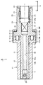
以下、本発明の実施の形態を、図面に示す実施例に基づき詳細に説明する。図1は、本発明の一実施例になるタップホルダを示す縦断面図である。タップホルダ10は、主な構成要素としてシャンク部材11およびタップホルダ本体21を備える。シャンク部材11は、略円筒形状であって、一点鎖線で表されるシャンク部材11の軸線に沿って延びる中心孔12を有するとともに、その外径が一定のストレート形状のシャンクであり、タップホルダ10の後端側に配置される。ストレート形状であるシャンク部材11の外周面13は、図示しない工具ホルダにチャッキングされる。中心孔12は、タップホルダ本体21の後端領域22aを受け入れて支持する。中心孔12の軸線方向後端部には、ロッド17が架設される。ロッド17は、シャンク部材11の軸線と直交して、中心孔12を横断する。ロッド17の両端は中心孔12の孔壁、つまりシャンク部材11、と強固に連結する。
Hereinafter, embodiments of the present invention will be described in detail based on examples shown in the drawings. FIG. 1 is a longitudinal sectional view showing a tap holder according to an embodiment of the present invention. The
タップホルダ本体21は、タップホルダ10の先端側に配置される。タップホルダ本体21は、その軸線方向後端領域22aが外径一定のストレート形状にされ、先端部にタップ(図示せず)を把持するための把持部23を有する。
The tap holder
タップホルダ本体21の軸線方向後端には軸線直角方向に延びる溝29が形成され、溝29は、シャンク部材11のロッド17を受け入れる。これによりタップホルダ本体21はシャンク部材11に対して回り止めされる。そしてタップ加工において、シャンク部材11の軸線周りの回転が、ロッド17を介してタップホルダ本体21に伝達される。また、溝29の軸線方向深さは、ロッド17の外径よりも大きい。これによりタップホルダ本体21は、シャンク部材11に対し、回り止めされたまま軸線方向に前進および後退することが可能である。
A
タップホルダ本体21の軸線方向先端部に設けられた把持部23につき簡単に説明すると、把持部23はタップの着脱作業が容易なワンタッチ式である。図示しないタップ根元部を受け入れる略円筒形状のタップスリーブ24は、タップホルダ本体21の先端部に形成された中心孔25に取り付け固定される。ワンタッチ式の構成は、タップスリーブ24に周方向に間隔を開けて配列されたボール26と、タップスリーブ24の後端と中心孔25の孔底25bとの間に縮設されたバネ27によって実現される。把持部23によって、タップの芯はタップホルダ本体21の中心線に固定される。
The gripping
タップホルダ本体21は、その後端領域22aがシャンク部材11の軸線に沿って延びる中心孔12に挿通されることから、シャンク部材の軸線方向に摺動可能に支持される。具体的には、後端領域22aの外径が一定であるのに対し、中心孔12は、後端側の内周面である後端部12bと、後端部12bよりも先端側にある相対的にやや大きな内径の境界部12cと、境界部12cよりも先端側にあって後端部12bよりも小さな内径の内周面であるガイド部12gとを有する。そして、タップホルダ本体21の後端領域22aの外周面は、中心孔12の内周面であるガイド部12gに緊密に接触して摺動可能に支持される。かかるガイド部12gにより、タップの芯およびタップホルダ本体21の中心線がシャンク部材11の軸線と一致する。
Since the
特に本実施例では、後端領域22aがタップホルダ本体21の軸線方向後端からタップホルダ本体21の軸線方向中央部まで形成される。そしてシャンク部材の先端部に設けられたガイド部12gが後端領域22aの先端側部位と摺接する。これにより、ガイド部12gはタップホルダ本体21の軸線方向中央部を案内することが可能となり、ガイド部12gは、タップの芯をシャンク部材11の軸線に精度よく一致させる。
In particular, in the present embodiment, the
シャンク部材11からみて、タップホルダ本体21は通常、基準位置Sにされる。ただし、主軸の回転と軸送りの誤差を吸収するため、タップホルダ本体21は矢印Cで示すようにシャンク部材11からみて軸線方向に後退し、または矢印Tで示すように軸線方向に前進する。このためタップホルダ10は、コンプレッション用弾性部材としてのコンプレッション用バネ31と、テンション用弾性部材としてのテンション用ウェーブスプリング32と、タップホルダ本体21の前進距離を所定範囲に規定して、シャンク部材11からタップホルダ本体21が抜け落ちることを防止するストッパ部材15とをさらに備える。
When viewed from the
コンプレッション用バネ31は、シャンク部材11とタップホルダ本体21との間の第1の位置に設けられて基準位置Sよりも軸線方向後端側Cへ後退したタップホルダ本体21を軸線方向先端側に付勢する。このときコンプレッション用バネ31は、軸線方向の圧縮力をうけて弾性変形することから、自己の復元力によりタップホルダ本体21を軸線方向先端側に付勢するのである。シャンク部材11の先端部は、この先端部よりも後端側の外周面13よりも外径側へ張り出し、シャンク外向きフランジ部14を構成する。また、タップホルダ本体21には、後端領域22aよりも先端側で、後端領域22aの外周面よりも外径側へ張り出した本体外向きフランジ部28が形成される。本体外向きフランジ部28の後端面28bは、シャンク外向きフランジ部14の先端面14fと対向する。前述した第1の位置は、タップホルダ本体21の外向きフランジ部28とシャンク部材11の先端部との間、具体的には後端面28bと先端面14fとの間、である。
The
先端面14fには、軸線方向後端側へ窪んだ有底の小穴11hが穿設される。小穴11hは軸線の周りに、周方向に間隔を開けて複数設けられる。コンプレッション用バネ31は、コイルバネであり、各小穴11hにそれぞれ配設される。
A bottomed
ストッパ部材15は、略円筒形状であって、シャンク外向きフランジ部14の外周に嵌合する。なお本実施例の他、ストッパ部材15の内周面に雌ねじを形成し、シャンク外向きフランジ部14の外周に雄ねじを形成し、両者を螺合してもよい。またストッパ部材15は、シャンク外向きフランジ部14から本体外向きフランジ部28を越えて軸線方向先端側に延び、本体外向きフランジ部28の外周を包囲する。そして、ストッパ部材15は、その先端部から内径側に張り出した内向きフランジ部16を含む。かくして、内向きフランジ部16は、本体外向きフランジ部28と対向し、タップホルダ本体21の前進距離を所定範囲に規制する。また、タップホルダ本体21の本体外向きフランジ部28が、シャンク部材11のシャンク外向きフランジ部14およびシャンク部材11と嵌合する内径側に張り出した内向きフランジ部16の間に配置されることから、基準位置SからT方向の前進距離およびC方向の後退距離がそれぞれ規制される。
The
テンション用ウェーブスプリング32は、シャンク部材11とタップホルダ本体21との間の第2の位置に設けられて基準位置Sよりも軸線方向先端側Tへ前進したタップホルダ本体21を軸線方向後端側に付勢する。このときテンション用ウェーブスプリング32は、軸線方向の圧縮力をうけて弾性変形することから、自己の復元力によりタップホルダ本体21を軸線方向後端側に付勢するのである。本体外向きフランジ部28の先端面28fは、内向きフランジ部16の後端面16bと対向する。前述した第2の位置は、ストッパ部材15の内向きフランジ部16と、タップホルダ本体21の外向きフランジ部28との間、具体的には後端面16bと先端面28fとの間、である。
The
なお図示はしなかったが、テンション用弾性部材として、上述したウェーブスプリング32に代えて、コイルバネを用いてもよい。かかるコイルバネは、バネ31に倣い、軸線の周りに周方向に間隔を空けて複数個配設される。
Although not shown, a coil spring may be used as the tension elastic member in place of the
タップホルダ本体21の中心孔25の孔底25bは、その中央で中心孔25よりも小さな断面寸法の角孔41と同軸に接続する。角孔41の先端は中心孔25と接続し、角孔41の後端は、相対的にさらに小さな直径の本体通路42と接続する。このように角孔41は中心孔25と本体通路42とを連通する連絡用の孔であり、断面形状が正方形などの矩形であって図示しないタップの後端角部を受け入れる。これら中心孔25、角孔41、および本体通路42は、相互に接続し、軸線に沿ってタップホルダ本体21の先端から後端まで一直線に延びる貫通孔を構成する。タップ加工において、図示しない工具ホルダから供給されるクーラントは、本体通路42、角孔41、中心孔25、および把持部23を順次流れて、図示しないタップに供給される。
The hole bottom 25b of the
本実施例の機能につき説明する。 The function of this embodiment will be described.
本実施例のタップホルダ10は、主軸に装着された工具ホルダ(ともに図示せず)にチャッキングされて、図示しないタップのピッチに合わせて回転および軸送りが同期する。しかしながら、軸送りに誤差が生じ回転と軸送りとがわずかにずれる場合がある。すなわち、主軸の回転と送りの誤差などによりタップホルダ本体21が軸線方向先端側(T)へ向かう力を受ける場合、本体外向きフランジ部28よりも先端側のテンション用ウェーブスプリング32が本体外向きフランジ部28から軸線方向の圧縮力を受ける。テンション用ウェーブスプリング32は弾性部材であることから、所定以上の圧縮力によって圧縮変形し、タップホルダ本体21の先端方向(T)への微小変位を許容する。これにより、タップがタップ自身のピッチに合うよう微小前進し、誤差を吸収して同期させることができる。
The
あるいは、主軸の回転と送りの誤差などによりタップホルダ本体21が軸線方向後端側(C)へ向かう力を受ける場合、本体外向きフランジ部28よりも後端側のコンプレッション用バネ31が本体外向きフランジ部28から軸線方向の圧縮力を受ける。コンプレッション用バネ31は弾性部材であることから、所定以上の圧縮力によって圧縮変形し、タップホルダ本体21の後端方向(C)への微小変位を許容する。これにより、タップがタップ自身のピッチに合うよう微小後退し、誤差を吸収して同期させることができる。
Alternatively, when the tap holder
そして、かかる微小前進および微小後退の間、タップの芯およびタップホルダ本体21の中心線は、シャンク部材11のガイド部12gによってシャンク部材11の軸線と一致する。
During the minute advance and minute retreat, the center line of the tap and the center line of the
かくして本実施例によれば、タップホルダ10における回転と軸送りの誤差を吸収することができ、しかもタップの芯をシャンク部材の軸線に一致させて、精度の高いタップ加工をすることができる。
Thus, according to the present embodiment, it is possible to absorb errors in rotation and axial feed in the
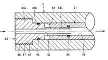
次に本発明の変形例を説明する。図2は本発明の変形例を示す縦断面図であり、この変形例では、シャンク部材11は、タップホルダ本体21の本体通路42を図示しない工具ホルダに接続するためのアダプタ44と、アダプタ44とシャンク部材11との隙間を封止する第1シール部材45を有する。アダプタ44は本体通路42と工具ホルダの通路(図示せず)との継ぎ目を好適な接続状態にするものである。
Next, a modification of the present invention will be described. FIG. 2 is a longitudinal sectional view showing a modification of the present invention. In this modification, the
シャンク部材11の中心孔12の後端部の内径は、環状段差46を境界として先端側よりも拡径されており、かかる内周面には雌ねじ47が形成される。また、アダプタ44の後端部44aの外周面には雄ねじ48が形成され、アダプタ44はシャンク部材11の後端部に螺合する。
The inner diameter of the rear end portion of the
アダプタ44は、その後端部44aの外径が最も大きく、中央部44bの外径が後端部44aよりも小さく、先端部44cの外径が中央部44bよりもさらに小さく、軸線方向の途中2箇所に環状段差を伴った3段の先細形状である。中央部44bの外周面には周方向溝が刻設されており、かかる周方向溝に第1シール部材45が嵌合する。第1シール部材45は、例えばゴム製のOリングであり、中心孔12の内周面と中央部44bの外周面の環状隙間を封止する。
In the
アダプタ44の先端部44cは、タップホルダ本体21の本体通路42に差し込まれる。ただしタップホルダ本体21はアダプタ44に対し微小な相対前進および後退が可能である。先端部44cの外周面には周方向溝が刻設されており、かかる周方向溝に第2シール部材49が嵌合する。第2シール部材49は、例えばゴム製のOリングであり、本体通路42の内周面と先端部44cの外周面の環状隙間を摺動可能に封止する。これにより、タップホルダ本体21は先端部44cに対して摺動することを妨げられない。
The
アダプタ44には、軸線に沿って延び、後端部44aから先端部44cまで貫通するアダプタ通路43が形成される。アダプタ通路43は、タップホルダ本体21の本体通路42と連通して工具ホルダ側まで延びる。
The
かかる変形例によれば、アダプタ通路43が形成されたアダプタ44と、第1シール部材45と、第2シール部材49を有することから、矢印の方向に、主軸および工具ホルダ側からタップホルダ10を経由してタップへクーラントを供給する際、高圧のクーラントが継ぎ目から漏れることを防止することができる。したがって継ぎ目から漏出したクーラントがタップホルダ本体21の後端側C(コンプレッション側)の動作に影響を与える懸念を解消することができ、タップホルダ本体21を基準位置Sへ確実に復帰させることができる。なお、アダプタ通路43および本体通路42は、クーラントに代えてエアを、タップへ供給することができる。
According to this modification, since the
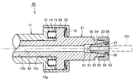
次に本発明の他の実施例を説明する。図3は、本発明の他の実施例になるタップホルダを示す縦断面図である。図3に示す実施例につき、上述した実施例と共通する構成については同一の符号を付して説明を省略し、異なる構成について以下に説明する。図3に示すタップホルダ50では、タップホルダ本体21の把持部23が、タップ101を把持する際にタップ101の芯をタップホルダ本体21の中心線に一致させる機構を有する。
Next, another embodiment of the present invention will be described. FIG. 3 is a longitudinal sectional view showing a tap holder according to another embodiment of the present invention. In the embodiment shown in FIG. 3, the same reference numerals are given to the same components as those in the above-described embodiment, and the description thereof is omitted, and different configurations will be described below. In the
当該機構として把持部23は、タップホルダ本体21の先端部に形成されたテーパ穴51と、テーパ穴51に嵌合してタップの根元部を把持するテーパコレット52と、タップホルダ本体21の先端部と螺合してテーパコレット52をテーパ穴51に押し込む筒状部材53を有する。
As the mechanism, the gripping
テーパ穴51は、その後端で連絡用の角孔41と接続し、タップホルダ本体21の中心線に沿って延び、先端側に向かうに連れて徐々に内径が大きくなる。テーパ穴51には、筒状のテーパコレット52が嵌合する。テーパコレット52の内周はタップ挿入孔54になっている。タップ挿入孔54はテーパコレット52の後端から先端まで軸線方向に貫通する。タップ挿入孔54には先端側からタップ101の根元部が挿入される。
The tapered
テーパコレット52の外周後端領域は、後端側へ向かうにつれて小径となる主テーパ面55になっている。主テーパ面55は、上述したテーパ穴51と嵌合する。
The outer peripheral rear end region of the
主テーパ面55と隣接するテーパコレット52の外周先端部には、全周に亘って延びるリング溝56が形成されており、リング溝56には筒状部材53が係合する。リング溝56の先端側の側壁を含むテーパコレット52の先端部57は、筒状部材53の凹部58に収容される。テーパコレット52は、軸線と平行に延在するスリット状のスリ割り(図示せず)を有する。スリ割りを押し縮めることによって、テーパコレット52はその径が変化可能である。
A
タップホルダ本体21の先端部外周に形成された雄ねじ59には、筒状部材53の内周に形成された雌ねじ62が螺合する。筒状部材53の先端部には内向きフランジ部が形成されて、かかる内向きフランジ部の内縁部がリング溝56と係合する。かくして筒状部材53は、テーパコレット52を軸線方向に移動させることができる。内向きフランジの先端面の内径縁には、リング状の凹部58が形成されている。凹部58の内径は、テーパコレット先端部57の外径よりも大きく、凹部58の軸線方向深さは先端部57の軸線方向厚みより大きい。これにより、テーパコレット先端部57は凹部58に完全に収容される。
A
筒状部材53はタップホルダ本体21に螺合してテーパコレット52を軸線後端方向へ押し込むためのものであり、テーパコレット52はテーパ穴51に押し付けられてタップ挿入孔54が縮径する。したがって、筒状部材53を回転させて締め込むと、タップ101が把持されるとともに、タップ101の芯がタップホルダ本体21の中心線に一致するよう位置決めされる。
The
これとは反対に、筒状部材53を回転させて緩めると、テーパコレット52をテーパ穴51から軸線先端方向へ離隔して、タップ挿入孔54の内径が広がり、タップ101の把持を解放する。
On the other hand, when the
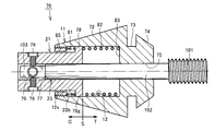
次に本発明のさらに他の実施例を説明する。図4は本発明のさらに他の実施例になるタップホルダを模式的に示す縦断面図である。図4に示す実施例につき、上述した実施例と共通する構成については同一の符号を付して説明を省略し、異なる構成について以下に説明する。図4に示すタップホルダ70では、シャンク部材11がタップホルダ本体21よりも先端側に配置される。またシャンク部材11は、その外径が後端に向かうに連れて細くなるテーパ形状のシャンクである。
Next, still another embodiment of the present invention will be described. FIG. 4 is a longitudinal sectional view schematically showing a tap holder according to still another embodiment of the present invention. In the embodiment shown in FIG. 4, the same components as those in the above-described embodiment are denoted by the same reference numerals, description thereof is omitted, and different configurations will be described below. In the
まずシャンク部材11につき説明すると、その外周面が軸線方向中央部から軸線方向後端に向かうにつれて細くなる先細形状のテーパ面72であることから、コレットとも称する。テーパ面72の先端側と隣接するコレット11の外周にはリング溝73が形成され、このリング溝73よりも先端側、つまりコレット11の先端部74は、リング溝73よりも相対的に大径に形成される。テーパ面72は、図示しない工具ホルダのテーパ穴に挿入される。そして、工具ホルダの先端部に螺合する筒状部材(図示せず)が、リング溝73に係合して、コレット11を軸線方向後端側に押し込む。この筒状部材を締め込むことにより、コレット11およびタップホルダ本体21の軸線は、工具ホルダにチャッキングされ、工具ホルダの軸線に一致するよう位置決めされる。なおコレット11にはスリ割りが形成されず、コレット11は縮径されないと理解されたい。
First, the
コレット11の軸線に沿って延びる中心孔12は、コレット11の後端から軸線方向中央部まで延び、中央孔12の孔底でタップ挿入孔75と接続する。タップ挿入孔75はコレット11の先端まで貫通し、タップ101の根元部102が挿通される。タップ挿入孔75の内径は中央孔12の内径よりも小さいことから、中央孔12の孔底は環状段差83に形成される。
The
次にタップホルダ本体21につき説明すると、タップホルダ本体21は軸線に沿って延びる貫通孔77が形成された略円筒形状の部材であり、先端部を除いた軸線方向中央領域および軸線方向後端部が外径一定である。そしてタップホルダ本体21の先端に相対的に大径のフランジ部78が形成されている。この先端フランジ部78の外周面はコレット11の中心孔12の内周面と摺接するガイド部78gである。
Next, the tap holder
タップホルダ本体21の後端部には、軸線直角方向に延びてタップホルダ本体21に螺合する止めねじ79が四方に設けられる。この止めねじ79および貫通孔77は、タップ101をタップホルダ本体21の軸線方向先端側で把持するための把持部を構成する。すなわち、タップ挿入孔75を貫通して中心孔12内に達する根元部102は、タップホルダ本体21の貫通孔77に受け入れられる。根元部102の後端部には断面正方形の角部103が形成される、そして、四方から止めねじ79を締め込むと、止めねじ79の先端が角部103の側面を押圧する。これにより、タップ101はタップホルダ本体21に抜け止め固定される。
At the rear end portion of the tap holder
タップホルダ本体21の先端領域22bは、コレット11の中心孔12に受け入れられて支持される。コレット11の後端部にはストッパ部材85が取り付け固定される。ストッパ部材85はリング形状であって、その外周面に雄ねじが形成される。また、中心孔12の内周面には、雌ねじ12sが形成され、かかる雌ねじ12sにリング形状のストッパ部材85が螺合する。コレット11に固定されたストッパ部材85はタップホルダ本体21の先端フランジ部78よりも軸線方向後端側に位置し、ストッパ部材85および先端フランジ部78は軸線方向に間隔を開けて対向する。これにより、タップホルダ本体21の後退距離が所定範囲に規制される。ストッパ部材85および先端フランジ部78間にはコンプレッション用弾性部材としてのコンプレッション用バネ81が縮設される。コンプレッション用バネ81の作用機能は、前述したコンプレッション用バネ31と同様である。
The
コレット11の中心孔12内において、環状段差83および先端フランジ部78間にはテンション用弾性部材としてのテンション用バネ82が縮設される。テンション用バネ82の作用機能は、前述したテンション用ウェーブスプリング32と同様である。環状段差83は、間隔をあけて、中心孔12の軸線方向中程に位置する先端フランジ部78と対向する。これにより、タップホルダ本体21の前進距離が所定範囲に規制される。
In the
図4に示すタップホルダ70では、タップホルダ本体21の先端フランジ部78のガイド部78gが中心孔12の内周面と摺接することから、タップホルダ本体21はコレット11の軸線方向に摺動可能に支持される。そして、中心孔12の内周面は、タップホルダ本体21の外周面であるガイド部12gに緊密に接触してタップホルダ本体21を摺動可能に支持する。かかるガイド部12gにより、タップの芯およびタップホルダ本体21の中心線がコレット11の軸線と一致する。
In the
先端領域22bは、タップホルダ本体21の軸線方向先端からタップホルダ本体21の軸線方向中央部まで形成される。そしてタップホルダ本体21の軸線方向先端部に形成されたガイド部78gは、中心孔12のうちストッパ部材85よりも先端側の内周面と摺接することにより、タップホルダ本体21の軸線方向先端部を案内する。これによりガイド部78gは、タップ101の芯をコレット11の軸線に一致させる。
The
以上、図面を参照してこの発明の実施の形態を説明したが、この発明は、図示した実施の形態のものに限定されない。図示した実施の形態に対して、この発明と同一の範囲内において、あるいは均等の範囲内において、種々の修正や変形を加えることが可能である。 Although the embodiments of the present invention have been described with reference to the drawings, the present invention is not limited to the illustrated embodiments. Various modifications and variations can be made to the illustrated embodiment within the same range or equivalent range as the present invention.
この発明になるタップホルダは、工作機械において有利に利用される。 The tap holder according to the present invention is advantageously used in a machine tool.
11 シャンク部材(コレット)、12 中心孔、12g ガイド部、14 シャンク外向きフランジ部、15 ストッパ部材、16 内向きフランジ部、17 ロッド、21 タップホルダ本体、23 把持部、24 タップスリーブ、25 中心孔、26 ボール、27 バネ、28 本体外向きフランジ部、31 コンプレッション用バネ、32 テンション用ウェーブスプリング、41 角孔、42 本体通路、43 アダプタ通路、44 アダプタ、45 第1シール部材、46 環状段差、49 第2シール部材、50 タップホルダ、51 テーパ穴、52 テーパコレット、53 筒状部材、54 タップ挿入孔、55 主テーパ面、56 リング溝、57 テーパコレット先端部、70 タップホルダ、72 テーパ面、73 リング溝、74 コレット先端部、75 タップ挿入孔、77 貫通孔、78 先端フランジ部、78g ガイド部、79 止めねじ、81 コンプレッション用バネ、82 テンション用バネ、83 環状段差、85 ストッパ部材、101 タップ、102 根元部。 11 Shank member (Collet), 12 Center hole, 12g Guide part, 14 Shank outward flange part, 15 Stopper member, 16 Inward flange part, 17 Rod, 21 Tap holder body, 23 Grip part, 24 Tap sleeve, 25 Center Hole, 26 Ball, 27 Spring, 28 Body outward flange, 31 Compression spring, 32 Tension wave spring, 41 Square hole, 42 Body passage, 43 Adapter passage, 44 Adapter, 45 First seal member, 46 Annular step , 49 Second seal member, 50 Tap holder, 51 Taper hole, 52 Taper collet, 53 Tubular member, 54 Tap insertion hole, 55 Main taper surface, 56 Ring groove, 57 Taper collet tip, 70 Tap holder, 72 Taper Surface, 73 ring groove, 74 Lett tip, 75 tap insertion hole, 77 through hole, 78 tip flange, 78g guide, 79 set screw, 81 compression spring, 82 tension spring, 83 annular step, 85 stopper member, 101 tap, 102 root .
Claims (10)
軸線方向後端領域が外径一定のストレート形状にされ、軸線方向先端部にタップを把持するための把持部を有し、前記後端領域が前記シャンク部材の中心孔に挿通されることにより前記シャンク部材に前進および後退可能に支持されるタップホルダ本体と、
前記シャンク部材と前記タップホルダ本体との間の第1の位置に設けられて基準位置よりも軸線方向後端側へ後退したタップホルダ本体を軸線方向先端側に付勢するコンプレッション用弾性部材と、
前記シャンク部材と前記タップホルダ本体との間の第2の位置に設けられて基準位置よりも軸線方向先端側へ前進したタップホルダ本体を軸線方向後端側に付勢するテンション用弾性部材とを備え、
前記シャンク部材の中心孔の内周面は、相対的に大きな内径の部分と、相対的に小さな内径の部分であって前記後端領域の外周面に緊密に接触して前記タップの芯を前記シャンク部材の軸線に一致させるガイド部とを含む、タップホルダ。 A shank member having a substantially cylindrical shape and having a central hole extending along an axis, and being chucked by a tool holder;
The axial rear end region has a straight outer shape with a constant outer diameter , and has a grip portion for gripping the tap at the axial front end portion, and the rear end region is inserted through the center hole of the shank member. A tap holder body supported by the shank member so as to be capable of moving forward and backward;
A compression elastic member that is provided at a first position between the shank member and the tap holder body and biases the tap holder body, which is retracted to the rear end side in the axial direction from the reference position, toward the front end side in the axial direction;
A tension elastic member provided at a second position between the shank member and the tap holder main body and biasing the tap holder main body that has advanced from the reference position toward the front end in the axial direction toward the rear end in the axial direction; Prepared,
The inner peripheral surface of the central hole of the shank member is a relatively large inner diameter portion and a relatively small inner diameter portion, and is in close contact with the outer peripheral surface of the rear end region so that the core of the tap is A tap holder including a guide portion that matches the axis of the shank member.
前記シャンク部材に前進および後退可能に支持され、タップを軸線方向先端側で把持するための把持部を有するタップホルダ本体と、
前記シャンク部材と前記タップホルダ本体との間の第1の位置に設けられて基準位置よりも軸線方向後端側へ後退したタップホルダ本体を軸線方向先端側に付勢するコンプレッション用弾性部材と、
前記シャンク部材と前記タップホルダ本体との間の第2の位置に設けられて基準位置よりも軸線方向先端側へ前進したタップホルダ本体を軸線方向後端側に付勢するテンション用弾性部材とを備え、
前記シャンク部材は、略円筒形状であって、軸線に沿って後端から先端側に向かって延びる中心孔と、軸線に沿って先端から後端に向かって延び前記中心孔と接続するタップ挿入孔とが形成され、前記中心孔に前記タップホルダ本体の先端領域を受け入れて前記タップホルダ本体を軸線方向に案内し、
前記タップホルダ本体は、前記中心孔の内周面と摺接する前記先端領域の先端部外周面に、前記タップの芯を前記シャンク部材の軸線に一致させるガイド部を有する、タップホルダ。 A shank member to be chucked in the tool holder;
A tap holder body supported by the shank member so as to be able to advance and retract, and having a grip portion for gripping the tap on the tip end side in the axial direction;
A compression elastic member that is provided at a first position between the shank member and the tap holder body and biases the tap holder body, which is retracted to the rear end side in the axial direction from the reference position, toward the front end side in the axial direction;
A tension elastic member provided at a second position between the shank member and the tap holder main body and biasing the tap holder main body that has advanced from the reference position toward the front end in the axial direction toward the rear end in the axial direction; Prepared,
The shank member has a substantially cylindrical shape, a center hole extending from the rear end toward the front end side along the axis, and a tap insertion hole extending from the front end toward the rear end along the axis to connect to the center hole Is formed, receives the tip region of the tap holder body in the center hole , guides the tap holder body in the axial direction ,
The tap holder main body has a guide portion that has a guide portion that aligns a core of the tap with an axis of the shank member on an outer peripheral surface of a tip portion of the tip region that is in sliding contact with an inner peripheral surface of the center hole.
請求項1に記載のタップホルダ。 Before SL guide portion is a distal end inner peripheral surface of the outer peripheral surface in sliding contact said central hole of said rear end region,
The tap holder according to claim 1.
前記シャンク部材は、該シャンク部材の外周に固定されて前記外向きフランジ部を越えて先端側へ延びる略円筒形状部と、前記円筒形状部の先端部から内径側に張り出した内向きフランジ部を含み、該内向きフランジ部が前記外向きフランジ部の先端面と対向して前記タップホルダ本体の前進距離を所定範囲に規制するストッパ部材をさらに有し、
前記テンション用弾性部材は、前記ストッパ部材の内向きフランジ部と、前記タップホルダ本体の外向きフランジ部との間に設けられる、請求項3に記載のタップホルダ。 The tap holder body further has an outward flange portion that protrudes to the outer diameter side on the tip side from the rear end region,
The shank member includes a substantially cylindrical portion that is fixed to the outer periphery of the shank member and extends to the distal end side beyond the outward flange portion, and an inward flange portion that projects from the distal end portion of the cylindrical portion to the inner diameter side. Including a stopper member that restricts the advancing distance of the tap holder body within a predetermined range so that the inward flange portion faces the distal end surface of the outward flange portion,
The tap holder according to claim 3, wherein the tension elastic member is provided between an inward flange portion of the stopper member and an outward flange portion of the tap holder body.
前記アダプタは、前記タップホルダ本体の本体通路と連通して工具ホルダ側まで延びるアダプタ通路が形成され、アダプタと前記タップホルダ本体との隙間を封止する第2シール部材を有する、請求項7に記載のタップホルダ。 The shank member has an adapter for connecting a main body passage of the tap holder main body to a tool holder, and a first seal member for sealing a gap between the adapter and the shank member,
The adapter includes a second seal member that is formed with an adapter passage that communicates with a body passage of the tap holder body and extends to the tool holder side, and that seals a gap between the adapter and the tap holder body. The described tap holder.
The tap holder according to any one of claims 1 to 8, wherein the shank member is a tapered shank whose outer diameter becomes narrower toward the rear end.
Priority Applications (1)
| Application Number | Priority Date | Filing Date | Title |
|---|---|---|---|
| JP2010239285A JP5179556B2 (en) | 2010-10-26 | 2010-10-26 | Tap holder |
Applications Claiming Priority (1)
| Application Number | Priority Date | Filing Date | Title |
|---|---|---|---|
| JP2010239285A JP5179556B2 (en) | 2010-10-26 | 2010-10-26 | Tap holder |
Publications (2)
| Publication Number | Publication Date |
|---|---|
| JP2012091251A JP2012091251A (en) | 2012-05-17 |
| JP5179556B2 true JP5179556B2 (en) | 2013-04-10 |
Family
ID=46385199
Family Applications (1)
| Application Number | Title | Priority Date | Filing Date |
|---|---|---|---|
| JP2010239285A Active JP5179556B2 (en) | 2010-10-26 | 2010-10-26 | Tap holder |
Country Status (1)
| Country | Link |
|---|---|
| JP (1) | JP5179556B2 (en) |
Families Citing this family (5)
| Publication number | Priority date | Publication date | Assignee | Title |
|---|---|---|---|---|
| JP6869536B2 (en) | 2017-05-17 | 2021-05-12 | エヌティーツール株式会社 | Tool holder |
| EP3628424A1 (en) | 2018-09-17 | 2020-04-01 | Korea Institute of Machinery & Materials | Cutting head operated by centrifugal force and cutting apparatus including the same |
| KR102068526B1 (en) * | 2019-03-25 | 2020-01-21 | 한국기계연구원 | Static and dynamically stable cutting units |
| JP6573300B1 (en) * | 2019-03-29 | 2019-09-11 | カトウ工機株式会社 | Machining tools |
| JP7261285B1 (en) | 2021-12-08 | 2023-04-19 | 株式会社日研工作所 | tap holder |
Family Cites Families (4)
| Publication number | Priority date | Publication date | Assignee | Title |
|---|---|---|---|---|
| JPS4947264Y1 (en) * | 1968-05-01 | 1974-12-25 | ||
| JPS4719890U (en) * | 1971-02-08 | 1972-11-06 | ||
| JPH0546812Y2 (en) * | 1986-05-30 | 1993-12-08 | ||
| EP2113329A4 (en) * | 2007-02-23 | 2011-01-19 | Daishowa Seiki | Tap holder |
-
2010
- 2010-10-26 JP JP2010239285A patent/JP5179556B2/en active Active
Also Published As
| Publication number | Publication date |
|---|---|
| JP2012091251A (en) | 2012-05-17 |
Similar Documents
| Publication | Publication Date | Title |
|---|---|---|
| JP5179556B2 (en) | Tap holder | |
| KR101828334B1 (en) | Holder device | |
| JP5420528B2 (en) | Device for adjusting the position of the blade of a rotary cutting tool | |
| TWI574773B (en) | Collet chuck, chuck apparatus, and method for manufacturing worked products | |
| US8550755B2 (en) | Tap driver for rigid/synchronous tapping | |
| CN106964813B (en) | A kind of method of precise hole organisation of working and manual processing precise hole | |
| WO2010090261A1 (en) | Main shaft device of machine tool | |
| KR20160053924A (en) | Cutting tool | |
| JPWO2008105043A1 (en) | Tap holder | |
| CN110678287A (en) | Knife handle | |
| US5284348A (en) | Apparatus for cutting ocular lens materials | |
| US2470218A (en) | Toolholder | |
| JP2017159372A (en) | Work support device | |
| JP6851092B2 (en) | Tool holder tightening method and tool holder | |
| JP6762042B2 (en) | Tool chuck, tool holding method and tool removal method | |
| JP4280253B2 (en) | Work rotation device | |
| JP2018103295A (en) | Attachment for machine tool tailstock | |
| CN212704824U (en) | Manual tapping hole tool | |
| US20050280216A1 (en) | Machine tool arbor fitted for tool-less chucking | |
| JP5079274B2 (en) | Tap holder | |
| JP7261285B1 (en) | tap holder | |
| TWM616042U (en) | Telescopic floating tapping tool chuck | |
| JP4331486B2 (en) | Work support device | |
| JP5946570B1 (en) | Tool holder | |
| JP2007168003A (en) | Tool holder |
Legal Events
| Date | Code | Title | Description |
|---|---|---|---|
| A131 | Notification of reasons for refusal |
Free format text: JAPANESE INTERMEDIATE CODE: A131 Effective date: 20121016 |
|
| A521 | Request for written amendment filed |
Free format text: JAPANESE INTERMEDIATE CODE: A523 Effective date: 20121210 |
|
| RD03 | Notification of appointment of power of attorney |
Free format text: JAPANESE INTERMEDIATE CODE: A7423 Effective date: 20121210 |
|
| TRDD | Decision of grant or rejection written | ||
| A01 | Written decision to grant a patent or to grant a registration (utility model) |
Free format text: JAPANESE INTERMEDIATE CODE: A01 Effective date: 20130108 |
|
| A61 | First payment of annual fees (during grant procedure) |
Free format text: JAPANESE INTERMEDIATE CODE: A61 Effective date: 20130109 |
|
| R150 | Certificate of patent or registration of utility model |
Ref document number: 5179556 Country of ref document: JP Free format text: JAPANESE INTERMEDIATE CODE: R150 |
|
| R250 | Receipt of annual fees |
Free format text: JAPANESE INTERMEDIATE CODE: R250 |
|
| R250 | Receipt of annual fees |
Free format text: JAPANESE INTERMEDIATE CODE: R250 |
|
| R250 | Receipt of annual fees |
Free format text: JAPANESE INTERMEDIATE CODE: R250 |
|
| R250 | Receipt of annual fees |
Free format text: JAPANESE INTERMEDIATE CODE: R250 |
|
| R250 | Receipt of annual fees |
Free format text: JAPANESE INTERMEDIATE CODE: R250 |
|
| R250 | Receipt of annual fees |
Free format text: JAPANESE INTERMEDIATE CODE: R250 |
|
| R250 | Receipt of annual fees |
Free format text: JAPANESE INTERMEDIATE CODE: R250 |
|
| R250 | Receipt of annual fees |
Free format text: JAPANESE INTERMEDIATE CODE: R250 |
|
| R250 | Receipt of annual fees |
Free format text: JAPANESE INTERMEDIATE CODE: R250 |
|
| R250 | Receipt of annual fees |
Free format text: JAPANESE INTERMEDIATE CODE: R250 |
|
| R250 | Receipt of annual fees |
Free format text: JAPANESE INTERMEDIATE CODE: R250 |