JP5172191B2 - Laser shock hardening processing method and laser shock hardening processing apparatus - Google Patents
Laser shock hardening processing method and laser shock hardening processing apparatus Download PDFInfo
- Publication number
- JP5172191B2 JP5172191B2 JP2007087616A JP2007087616A JP5172191B2 JP 5172191 B2 JP5172191 B2 JP 5172191B2 JP 2007087616 A JP2007087616 A JP 2007087616A JP 2007087616 A JP2007087616 A JP 2007087616A JP 5172191 B2 JP5172191 B2 JP 5172191B2
- Authority
- JP
- Japan
- Prior art keywords
- laser beam
- laser
- processed
- shock hardening
- laser shock
- Prior art date
- Legal status (The legal status is an assumption and is not a legal conclusion. Google has not performed a legal analysis and makes no representation as to the accuracy of the status listed.)
- Active
Links
Images


Landscapes
- Laser Beam Processing (AREA)
Description
本発明は、金属やセラミックスなどの固体材料の表面に液体を介してパルス状のレーザビームを照射することにより、材料表面および内部の組織、硬さ、残留応力などの特性を調整するレーザ衝撃硬化処理方法およびそのための処理装置に関する。 The present invention is a laser shock hardening that adjusts the characteristics of the material surface and internal structure, hardness, residual stress, etc. by irradiating the surface of a solid material such as metal or ceramics with a pulsed laser beam via a liquid. The present invention relates to a processing method and a processing apparatus therefor.
腐食や亀裂の発生など、構造物の損傷は表面を起点とする場合がほとんどであり、構造物の寿命は表面の特性に左右される。このため、各種の表面処理技術を適用して材料表面の機械的あるいは化学的な性質を改善し、疲労強度、耐腐食性、耐摩耗性などを向上させることにより、構造物の寿命延長を図る試みが行なわれている。 In most cases, damage to structures such as corrosion and cracks originates from the surface, and the life of the structure depends on the characteristics of the surface. For this reason, various surface treatment technologies are applied to improve the mechanical or chemical properties of the material surface, thereby improving the fatigue strength, corrosion resistance, wear resistance, etc., thereby extending the life of the structure. An attempt is being made.
ショットピーニングは代表的な表面処理技術であり、部材表面層の硬さの上昇と、表面層への圧縮残留応力の導入が可能である。このため、自動車、航空機などの産業分野で多く利用されている。 Shot peening is a typical surface treatment technique, and can increase the hardness of the member surface layer and introduce compressive residual stress into the surface layer. For this reason, it is widely used in industrial fields such as automobiles and aircraft.
一方、レーザはエネルギー密度や照射位置の精密かつ高速な制御が容易であり、他の方法では困難な高速処理、超急熱急冷処理などを行なうことができるため、種々の技術が開発され、材料の加工処理への応用が拡大している。 Lasers, on the other hand, are capable of precise and high-speed control of energy density and irradiation position, and can perform high-speed processing and super rapid thermal quenching that are difficult with other methods. The application to processing is expanding.
その一つとして、液体を介して材料の表面にパルス状のレーザビームを照射するレーザ衝撃硬化処理があり、ショットピーニングと同様に部材表面層の硬さの上昇と、表面層への圧縮残留応力の導入を行なうことが可能である。 As one of them, there is a laser shock hardening treatment that irradiates the surface of the material with a pulsed laser beam via a liquid. Like shot peening, the hardness of the member surface layer is increased and the compressive residual stress on the surface layer is increased. Can be introduced.
レーザ衝撃硬化処理は、ショットピーニングと比較して効果が高く、非接触作業が可能、反力がない、レーザ照射の条件や部位を精密に制御できる等、ショットピーニングでは実現できない優れた利点があり、開発および実用化が進められている(特許文献1ないし特許文献5参照)。
Laser shock hardening is more effective than shot peening, has non-contact work, no reaction force, and has excellent advantages that cannot be realized by shot peening, such as precise control of laser irradiation conditions and parts. Development and practical use are underway (see
特許文献5には、金属やセラミックスなどの固体材料の表面に、液体を介してパルス状のレーザビームを照射することにより、材料表面および内部の組織、硬さ、残留応力などの材料特性を調整するレーザ衝撃硬化処理について開示されている。 In Patent Document 5, the surface of a solid material such as metal or ceramics is irradiated with a pulsed laser beam through a liquid, thereby adjusting the material characteristics such as the material surface and the internal structure, hardness, and residual stress. A laser shock hardening process is disclosed.
特許文献5によれば、レーザビームのピーク出力密度が被処理部材のプラズマ発生閾値(金属の場合概ね0.1〜10TW/m2)を超えると、被処理部材のごく表層(1μm以下)が瞬時に蒸発し、プラズマが発生する。液体中では慣性が瞬間的に強く働くため、プラズマはほとんど膨張することができず、狭い領域にレーザビームのエネルギーが集中する。このため、プラズマの圧力は大気中や真空中と比較して十〜百倍にも達する。 According to Patent Document 5, when the peak output density of the laser beam exceeds the plasma generation threshold of the member to be processed (approximately 0.1 to 10 TW / m 2 in the case of metal), the very surface layer (1 μm or less) of the member to be processed is formed. It instantly evaporates and plasma is generated. Inertia momentarily works strongly in the liquid, so that the plasma can hardly expand and the energy of the laser beam is concentrated in a narrow area. For this reason, the pressure of the plasma reaches 10 to 100 times that in the atmosphere or vacuum.
液体として水を使用した場合、被処理部材に照射されるレーザビームのピーク出力密度をI(TW/m2)とすると、発生するプラズマの圧力P(GPa)は概ね、P=(0.2×I)0.5となる。被処理部材の設置雰囲気が油、アルコール、アンモニア水、ホウ酸水など、水以外の液体の場合には、次の係数kを使用してP=(0.2×I×k)0.5により、プラズマの圧力を求めることができる。 When water is used as the liquid, if the peak output density of the laser beam applied to the member to be processed is I (TW / m 2 ), the pressure P (GPa) of the generated plasma is approximately P = (0.2 XI) 0.5 . When the installation atmosphere of the member to be treated is a liquid other than water, such as oil, alcohol, ammonia water, boric acid water, etc., P = (0.2 × I × k) 0.5 using the following coefficient k. Thus, the pressure of the plasma can be obtained.
k=(液体の音響インピーダンス)/(水の音響インピーダンス)
ここで、液体の音響インピーダンスは、(液体の密度)×(液体中の音速)であるため、前記した液体であれば、プラズマの圧力は水の場合と大きくは変わらない。したがって、被処理部材の表面でレーザビームのピーク出力密度が1〜100TW/m2となるようにレーザビームの大きさおよびパルスエネルギーを制御すれば、プラズマの圧力は概ね450MPa〜45GPaとなる。
k = (acoustic impedance of liquid) / (acoustic impedance of water)
Here, since the acoustic impedance of the liquid is (the density of the liquid) × (the speed of sound in the liquid), in the case of the above-described liquid, the plasma pressure is not significantly different from that in the case of water. Therefore, if the laser beam size and pulse energy are controlled so that the peak output density of the laser beam is 1 to 100 TW / m 2 on the surface of the member to be processed, the plasma pressure is approximately 450 MPa to 45 GPa.
このようにして発生した高圧のプラズマは、被処理部材の表面を瞬間的に圧縮し、圧縮による表面の変位は衝撃波となって部材の深さ方向に伝播する。このとき、衝撃波の圧力が部材の降伏応力を上回ると、局所的な塑性変形が生じるため、組織、硬さ、残留応力などの材料特性を調整することができる。 The high-pressure plasma generated in this way instantaneously compresses the surface of the member to be processed, and the displacement of the surface due to the compression becomes a shock wave and propagates in the depth direction of the member. At this time, if the pressure of the shock wave exceeds the yield stress of the member, local plastic deformation occurs, so that material characteristics such as the structure, hardness, and residual stress can be adjusted.
レーザ衝撃硬化処理により材料表面の硬さが上昇し、圧縮の残留応力が形成されると、疲労強度の向上や応力腐食割れの予防に効果がある。そのため、航空機産業、自動車産業、原子力産業などでレーザ衝撃硬化処理の適用が進められている。 When the hardness of the material surface is increased by the laser shock hardening process and a compressive residual stress is formed, it is effective in improving fatigue strength and preventing stress corrosion cracking. Therefore, application of laser shock hardening is being promoted in the aircraft industry, the automobile industry, the nuclear power industry, and the like.
レーザ衝撃硬化処理は、パルス状のレーザビームを被処理部材の表面に直接照射するため、プラズマによって分解された液体の構成元素が被処理部材の表面と反応する場合がある。 In the laser shock hardening process, since the pulsed laser beam is directly irradiated on the surface of the member to be processed, the constituent elements of the liquid decomposed by the plasma may react with the surface of the member to be processed.
たとえば、水雰囲気でステンレス鋼をレーザ衝撃硬化処理する場合、水の分解によって水素と酸素が発生し、酸素がステンレス鋼の表面と反応するため、レーザ衝撃硬化処理後の表面にはFe3O4を主成分とする厚さ約1μmの強固な黒色の酸化被膜が形成される。 For example, when laser shock hardening treatment is performed on stainless steel in a water atmosphere, hydrogen and oxygen are generated by the decomposition of water, and oxygen reacts with the surface of the stainless steel. Therefore, the surface after the laser shock hardening treatment is Fe 3 O 4. As a result, a strong black oxide film having a thickness of about 1 μm is formed.
黒色の被膜が外観上好ましくない場合には、塗料や金属テープなどにより被処理部材の表面にあらかじめ厚さ数十μm程度の被膜を形成した後レーザ衝撃硬化処理を施せば、被膜除去後の被処理部材の表面は処理前とほとんど同一の表面性状を示す。
前記した例は、国内で実施された実験の結果であるが、欧米ではレーザのパルスエネルギーをさらに高め、100J程度で実験を行なっている。その結果、圧縮残留応力の深さは表面から数mmにも及び、さらに高い効果が期待されている。しかしながら、高いパルスエネルギーでレーザピーニングを行なった場合、材料の表面が溶融するため、表面から数十μmの領域が逆に引張の応力状態となってしまうことが知られている(非特許文献1)。 The example described above is the result of an experiment conducted in Japan. In Europe and the United States, the laser pulse energy is further increased, and the experiment is performed at about 100 J. As a result, the depth of the compressive residual stress reaches several mm from the surface, and a higher effect is expected. However, when laser peening is performed with high pulse energy, the surface of the material melts, and it is known that a region of several tens of μm from the surface becomes a tensile stress state (Non-Patent Document 1). ).
このため、高エネルギーでレーザピーニングを行なう場合には、遮熱のためのコーティングを材料の表面にあらかじめ施し、その後レーザピーニング処理を行なっているが、工程が複雑となり、コストの増大とスループットの低下を招いている。 For this reason, when laser peening is performed with high energy, a coating for heat shielding is applied to the surface of the material in advance, and then laser peening is performed, but the process becomes complicated, increasing costs and lowering throughput. Is invited.
本発明は、従来技術に伴うこれらの課題を解決することを目的としてなされたものであり、表面のコーティングが不要で、被処理部材の硬さの上昇および残留応力の改善効果が深い領域まで及び、大面積を高速でレーザピーニング処理することが可能なレーザ衝撃硬化処理方法およびそのための処理装置を提供するものである。 The present invention has been made for the purpose of solving these problems associated with the prior art, does not require surface coating, extends to a region where the hardness of the processed member is increased and the effect of improving residual stress is deep. The present invention provides a laser shock hardening method and a processing apparatus therefor capable of performing a laser peening process on a large area at high speed.
また、本発明の目的は、駆動装置に過剰な負荷をかけず十分高速な処理ができるようにしたレーザ衝撃硬化処理方法およびそのための処理装置を提供することにある。 Another object of the present invention is to provide a laser shock hardening processing method and a processing apparatus therefor that can perform sufficiently high-speed processing without applying an excessive load to the driving device.
上記の目的を達成するために、本発明に係るレーザ衝撃硬化処理方法は、液体に接した被処理部材の表面に液体を通してパルス状のレーザビームを照射し、被処理部材の表面処理を行なうレーザ衝撃硬化処理方法において、前記被処理部材の表面に1パルスで形成されるレーザビームの照射スポットが、複数の小領域で構成されていることを特徴とする。 In order to achieve the above object, a laser shock hardening method according to the present invention is a laser that performs surface treatment of a member to be treated by irradiating the surface of the member to be treated with the pulsed laser beam through the liquid. In the impact hardening method, the laser beam irradiation spot formed in one pulse on the surface of the member to be processed is composed of a plurality of small regions.
また、本発明に係るレーザ衝撃硬化処理装置は、レーザビームを出射するレーザ発振器と、被処理部材の表面におけるレーザビームの照射スポットが複数の小領域で構成されるように前記レーザ発振器から出射されたレーザビームの照射スポット形状を整形する光学装置と、被処理部材の表面に沿ってレーザビームを相対的に移動させ被処理部材の所望の部位にレーザビームを位置決めするための駆動装置と、被処理部材の少なくともレーザビームによって照射される表面に液体を供給するための液体供給手段と、を有すること、を特徴とする。 Further, the laser shock hardening processing apparatus according to the present invention emits a laser beam from the laser oscillator so that the laser beam irradiation spot on the surface of the member to be processed is composed of a plurality of small regions. An optical device for shaping the irradiated spot shape of the laser beam, a drive device for relatively moving the laser beam along the surface of the member to be processed and positioning the laser beam at a desired part of the member to be processed; And a liquid supply means for supplying a liquid to at least the surface irradiated with the laser beam of the processing member.
本発明によれば、レーザビームの照射スポットを複数の小領域で構成することにより、各小領域で微小なプラズマが形成されるため、従来技術に比較して液体との接触面積が増大する。その結果、プラズマの冷却が促進され、被処理部材表面に対するプラズマからの入熱量が減り、高いエネルギーのレーザパルスを使用した場合においても表面を溶融させることなくレーザピーニングすることが可能となる。 According to the present invention, by forming a laser beam irradiation spot in a plurality of small regions, a minute plasma is formed in each small region, so that the contact area with the liquid is increased as compared with the prior art. As a result, cooling of the plasma is promoted, the amount of heat input from the plasma to the surface of the member to be processed is reduced, and laser peening can be performed without melting the surface even when a high energy laser pulse is used.
また、本発明によれば、レーザビームの照射スポットを複数の小領域に分割するため、従来技術に比較して1パルスで処理できる面積が増加し、より高速に処理を行なうことが可能となる。 Further, according to the present invention, since the laser beam irradiation spot is divided into a plurality of small regions, the area that can be processed with one pulse is increased as compared with the prior art, and processing can be performed at higher speed. .
以下、本発明の実施の形態について図面を参照して説明する。 Hereinafter, embodiments of the present invention will be described with reference to the drawings.
[第1の実施形態]
図1は、本発明の第1の実施形態によるレーザ衝撃硬化処理方法を示す説明図である。
[First Embodiment]
FIG. 1 is an explanatory view showing a laser shock hardening method according to the first embodiment of the present invention.
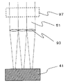
被処理部材41は保持台42に設置され、被処理部材41および保持台42は容器21内に置かれ、容器21内には液体22が満たされている。保持台42は、被処理部材41を固定し、高さおよび角度調整などを行なうための位置調整機能を備えている。
The member to be processed 41 is installed on the holding table 42, and the member to be processed 41 and the holding table 42 are placed in the
レーザ発振器11から出射したパルス状レーザビーム51は、出力調整装置12、シャッター13、ビーム拡大器91、固定ミラー92および移動ミラー94を介して照射ヘッド17に入射する。照射ヘッド17から出射したレーザビーム51は、液体22中の被処理部材41に向けて照射される。また、駆動装置30により、照射ヘッド17および移動ミラー94を被処理部材41の表面に倣って移動させながらレーザビーム51を照射することにより、被処理部材41の表面の所定の処理領域を衝撃硬化処理する。
The
ここで、レーザ発振器11としては、たとえば、波長約1mmの近赤外で発振するガラスレーザやNd:YAGレーザが使用される。液体22として水を使用する場合、近赤外の光は水に吸収されやすいため、水深は数mm以下とする必要があるが、被処理部材41が複雑な形状のときには、水深を数mmに制御することは難しい。このため、水にほとんど吸収されず、水深の制限がないNd:YAGレーザの第2高調波(波長0.53mm)をレーザ発振器11として使用することが好ましい。
Here, as the
出力調整装置12は、偏光板とビーム分岐器の組合せなどによって構成され、レーザビーム51のエネルギーを調整する光学装置である。シャッター13は、高速動作ミラーなどで構成され、駆動装置30と同期して開閉制御することにより、被処理部材41の表面の必要な部分にのみレーザビーム51を照射することができるようになっている。また、ビーム拡大器91はレーザビーム51の大きさを拡大または縮小し、照射ヘッド17に入射するレーザビーム51の大きさを調整する機能を有している。
The
照射ヘッド17は、レーザビーム51の方向に垂直な方向の軸を有する複数の円柱状凸レンズ93を備え、図2に示すように、レーザビーム51を複数に分割するとともに、その各々をライン状に絞り込みながら被処理部材41の表面に照射する機能を有する。したがって、照射ヘッド17と被処理部材41の距離を変化させることにより、被処理部材41の表面に照射されるレーザビーム51の面積が変化し、被処理部材41の表面に照射されるレーザビーム51のピーク出力密度(I(TW/m2))も変化する。
The irradiation head 17 includes a plurality of cylindrical
レーザ衝撃硬化処理の効果はプラズマ52の圧力(P=(0.2×I)0.5)によって決まるため、その効果を保証するためには、該ピーク出力密度を所定の範囲に保つ必要がある。このため、被処理部材41を保持する保持台42は位置調整機能を有し、被処理部材41の位置調整により概略の調整を行なうとともに、駆動装置30により照射ヘッド17の高さを制御することにより、照射ヘッド17と被処理部材41の距離を所定の範囲に保っている。
Since the effect of the laser shock hardening process is determined by the pressure of the plasma 52 (P = (0.2 × I) 0.5 ), it is necessary to keep the peak power density within a predetermined range in order to guarantee the effect. is there. For this reason, the holding table 42 that holds the member to be processed 41 has a position adjustment function, and performs rough adjustment by adjusting the position of the member to be processed 41, and the height of the irradiation head 17 is controlled by the driving
ここで、超音波距離計またはレーザ距離計などの距離計測装置(図示せず)を使用して照射ヘッド17と被処理部材41の距離を測定し、照射ヘッド17の高さを制御することが行なわれる。また、レーザビーム51の照射によるプラズマ52の発生音の到達時間により照射ヘッド17の高さを制御することも可能である。さらに、処理部材41の表面で反射されたレーザビーム51の反射強度を測定することにより、照射ヘッド17の高さを制御することも可能である。
Here, it is possible to control the height of the irradiation head 17 by measuring the distance between the irradiation head 17 and the member to be processed 41 using a distance measuring device (not shown) such as an ultrasonic distance meter or a laser distance meter. Done. It is also possible to control the height of the irradiation head 17 by the arrival time of the generated sound of the
レーザビーム51の照射によって発生したプラズマ52は、短時間(10−7秒程度)でエネルギーを失って冷却され、微粒子となって液体中に浮遊する。この状態で、次のレーザビームを照射すると、微粒子がレーザのエネルギーを吸収したり散乱したりするため、効率の良いレーザ衝撃硬化処理ができない。
The
本実施形態では、微粒子の浮遊を防止するため、液体供給装置20を容器21に接続し、常に清浄な液体22を供給することが行なわれる。ここで、液体供給装置20は、ポンプ、フィルター、流量計(図示せず)などで構成される。
In the present embodiment, in order to prevent fine particles from floating, the
なお、本実施形態では、照射ヘッド17を移動させることにより、被処理部材41の表面の所定の範囲をレーザ衝撃硬化処理する場合について説明したが、照射ヘッド17を固定して被処理部材41を移動させる場合、照射ヘッド17と被処理部材41を同時に移動させる場合にも全く同じ効果があることは言うまでもない。 In the present embodiment, the case where the predetermined range of the surface of the member to be processed 41 is subjected to the laser shock hardening process by moving the irradiation head 17 is described, but the irradiation head 17 is fixed and the member to be processed 41 is fixed. Needless to say, the same effect can be obtained when the irradiation head 17 and the member to be processed 41 are moved simultaneously.
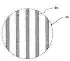
図3は、本実施形態により、被処理部材41上に照射されるレーザビーム51の形状を模式的に表した図である。通常、レーザ発振器11から出射されたレーザビーム51の形状は円形であることが多い。その場合、複数の円柱状凸レンズ93によって、照射スポット45は複数の小領域46に分割される。ただし、この実施形態では、各小領域46は、たとえば等間隔の互いに平行な直線状である。したがって、プラズマ52は各小領域(ライン)46状に発生し、ライン間の液体により容易に冷却される。その結果、被処理部材41の表面への入熱量が激減し、表面の溶融を避けることができ、被処理部材41の表面に遮熱コーティングを施すことなく表面に圧縮の残留応力を形成することができる。また、ライン間の面積も、1パルスで処理できる面積に含まれるため、より高速な処理が可能となる。
FIG. 3 is a diagram schematically showing the shape of the
図4は、1パルスで処理する面積(照射スポット45の面積であって、図3の破線の円の面積)に対する小領域46の面積(各ラインの面積の合計)の割合と、残留応力改善効果の関係を示す図である。この割合が概ね30%〜70%の範囲で有効なことがわかる。
FIG. 4 shows the ratio of the area of the small region 46 (the total area of each line) to the area processed by one pulse (the area of the
本実施形態によれば、レーザビームの照射スポットを複数の小領域で構成することにより、各小領域で微小なプラズマが形成されるため、従来技術に比較して液体との接触面積が増大する。その結果、プラズマの冷却が促進され、被処理部材表面に対するプラズマからの入熱量が激減し、高いエネルギーのレーザパルスを使用した場合においても表面を溶融させることなくレーザピーニングすることが可能となる。 According to the present embodiment, by forming the laser beam irradiation spot in a plurality of small regions, a minute plasma is formed in each small region, so that the contact area with the liquid is increased as compared with the prior art. . As a result, the cooling of the plasma is promoted, the amount of heat input from the plasma to the surface of the member to be processed is drastically reduced, and even when a high energy laser pulse is used, laser peening can be performed without melting the surface.
また、本実施形態によれば、レーザビームの照射スポットを複数の小領域46に分割するため、従来技術に比較して1パルスで処理できる面積が増加し、より高速に処理を行なうことが可能となる。
In addition, according to the present embodiment, the laser beam irradiation spot is divided into a plurality of
たとえば、溶接線に沿った帯状の領域を処理する場合、通常は10mm幅程度の処理が必要となり、2次元的な駆動が必要であったが、本発明によれば1パルスで広い領域を処理することが可能となるため、1方向のみの動作で処理を完了させることができる。 For example, when processing a band-shaped region along a weld line, processing of about 10 mm width is usually required, and two-dimensional driving is required. However, according to the present invention, a wide region is processed with one pulse. Therefore, the process can be completed with an operation in only one direction.
また、微小なプラズマから発生した衝撃波は被処理部材の内部を伝播するに従って周囲の衝撃波と合体し、より広い面積の衝撃波が形成される。その結果、波面の広がりによる衝撃波の減衰が抑制されるため、従来技術に比較して被処理部材内部のより深い領域まで効果を及ぼすことが可能となる。 Further, the shock wave generated from the minute plasma is combined with the surrounding shock wave as it propagates inside the member to be processed, and a shock wave having a wider area is formed. As a result, shock wave attenuation due to the spread of the wavefront is suppressed, and it is possible to exert an effect up to a deeper region inside the member to be processed as compared with the prior art.
このように、本実施形態によれば、被処理部材の表面にコーティングを施さずに高いエネルギーのレーザパルスを使用しても、表面を溶融させることなくレーザピーニングすることが可能であり、その効果は従来技術に比較してより大きく、より高速な処理を行なうことができる。また、駆動装置に対する負荷が軽減されるため、駆動装置をより小型でシンプルなものにすることができる。 Thus, according to the present embodiment, even if a high energy laser pulse is used without coating the surface of the member to be processed, laser peening can be performed without melting the surface, and the effect Is larger than the prior art and can perform faster processing. Further, since the load on the drive device is reduced, the drive device can be made smaller and simpler.
さらにこの実施形態の変形例として、図2に点線で示すホモジナイザ97を用いれば、照射スポット45の各ラインの出力密度をほぼ一定に制御することが可能であり、より高品質の処理を行なうことができる。
Further, as a modification of this embodiment, if a
[第2の実施形態]
次に、図5を参照して、本発明の第2の実施形態によるレーザ衝撃硬化処理方法を説明する。ここで、第1の実施形態と共通する部分の重複説明は省略する。この実施形態では、図1に示す第1の実施形態における円柱状凸レンズ93の組を2組直列に並べて用いる。2組の円柱状凸レンズ93は、円柱軸が互いに直交する配置とする。
[Second Embodiment]
Next, a laser shock hardening method according to the second embodiment of the present invention will be described with reference to FIG. Here, the overlapping description of the parts common to the first embodiment is omitted. In this embodiment, two sets of cylindrical
図5は、本発明の第2の実施形態に係る、被処理部材41上に照射されるレーザビーム51の形状を模式的に表した図である。この場合、複数の円柱状凸レンズ93を2組用い、その2組がほぼ直交する配置することにより、この照射形状を得ることができる。照射スポット45の各小領域46は、この場合2次元的に等間隔に配列されたドットマトリックス状の形態を示す。したがって、プラズマ52は各ドット上に発生し、ドット間の液体により容易に冷却される。その結果、被処理部材41の表面への入熱量が激減し、表面の溶融を避けることができ、被処理部材41の表面に遮熱コーティングを施すことなく表面に圧縮の残留応力を形成することができる。また、ドット間の面積も、1パルスで処理できる面積に含まれるため、より高速な処理が可能となる。
FIG. 5 is a diagram schematically showing the shape of the
第1の実施形態と同様に、1パルスで処理する面積(照射スポット45の面積であって、図5の破線の円の面積)に対する小領域46の面積(各小正方形の面積の合計)の割合と、残留応力改善効果の関係を求めたところ、この割合が、図4と同様に概ね30%〜70%の範囲で有効なことがわかった。
Similarly to the first embodiment, the area of the small region 46 (the total area of each small square) with respect to the area processed with one pulse (the area of the
さらに、図2に点線で示すホモジナイザ97を用いれば、照射スポット45の各小領域(ドット)46の出力密度をほぼ一定に制御することが可能であり、より高品質の処理を行なうことができることは、第1の実施形態と同様である。
Furthermore, if the
[他の実施形態]
以上説明した各実施形態は単なる例示であって、本発明はこれらの実施形態の具体的構成に限定されるものではない。
[Other Embodiments]
The embodiments described above are merely examples, and the present invention is not limited to the specific configurations of these embodiments.
たとえば、図2の円柱状凸レンズ93の代わりに、図6に示すように、六角形状のマイクロレンズの2次元アレイ99を用いれば、第2の実施形態における図5の照射スポット45の各小領域46は六角形になる。また、平板ガラス上に小型の円形凸レンズを2次元的に並べたレンズアレイを用いれば、図5の照射スポット45の各小領域46は円形になる。
For example, if a two-
また、図1に示す例では、被処理部材41が液体22内に浸漬されている。このように被処理部材41を液体22内に浸漬する代わりに、被処理部材41にレーザビーム51が照射される部分に向けて液体を噴射させて被処理部材41に沿った液膜を形成させてもよい。
In the example shown in FIG. 1, the member to be processed 41 is immersed in the liquid 22. In this way, instead of immersing the member to be processed 41 in the liquid 22, the liquid is ejected toward the portion to be irradiated with the
また、図1に示す例では、円柱状凸レンズを用いてレーザビームの照射スポット形状を整形するものとしたが、円柱状凸レンズの代わりに円柱状凹面鏡を用いることもできる。 In the example shown in FIG. 1, the shape of the laser beam irradiation spot is shaped using a cylindrical convex lens, but a cylindrical concave mirror can be used instead of the cylindrical convex lens.
10・・・レーザ照射装置
11・・・レーザ発振器
12・・・出力調整装置
13・・・シャッター
17・・・照射ヘッド
20・・・液体供給装置
21・・・容器
22・・・液体
30・・・駆動装置
41・・・被処理部材
42・・・保持台
45・・・照射スポット
46・・・小領域
51・・・レーザビーム
52・・・プラズマ
91・・・ビーム拡大器
92・・・固定ミラー
93・・・円柱状凸レンズ
94・・・移動ミラー
97・・・ホモジナイザ
99・・・マイクロレンズアレイ
DESCRIPTION OF
Claims (12)
前記被処理部材の表面に1パルスで形成されるレーザビームの照射スポットが、複数の小領域で構成されていることを特徴とするレーザ衝撃硬化処理方法。 In a laser shock hardening method for performing surface treatment of a member to be treated by irradiating the surface of the member to be treated in contact with the liquid with a pulsed laser beam through the liquid,
A laser shock hardening method, wherein an irradiation spot of a laser beam formed by one pulse on the surface of the member to be processed is composed of a plurality of small regions.
被処理部材の表面におけるレーザビームの照射スポットが複数の小領域で構成されるように前記レーザ発振器から出射されたレーザビームの照射スポット形状を整形する光学装置と、
被処理部材の表面に沿ってレーザビームを相対的に移動させ被処理部材の所望の部位にレーザビームを位置決めするための駆動装置と、
被処理部材の少なくともレーザビームによって照射される表面に液体を供給するための液体供給手段と、
を有すること、を特徴とするレーザ衝撃硬化処理装置。 A laser oscillator for emitting a laser beam;
An optical device for shaping the irradiation spot shape of the laser beam emitted from the laser oscillator so that the irradiation spot of the laser beam on the surface of the member to be processed is composed of a plurality of small regions;
A driving device for relatively moving the laser beam along the surface of the member to be processed and positioning the laser beam at a desired portion of the member to be processed;
A liquid supply means for supplying a liquid to at least a surface irradiated with a laser beam of a member to be processed;
A laser shock hardening apparatus characterized by comprising:
レーザビームを横切る第1の方向に軸を配置して、レーザビームを横切って配列された複数の第1の円柱状凸レンズまたは円柱状凹面鏡と、
レーザビームを横切り前記第1の方向に垂直な第2の方向に軸を配置して、レーザビームを横切って配列された複数の第2の円柱状凸レンズまたは円柱状凹面鏡と、
を備え、
前記第1および第2の円柱状凸レンズまたは円柱状凹面鏡それぞれから出射されるレーザビームが、2次元的に配列された複数の小領域に分割されるように整形されて被処理部材の表面に照射されるように構成されていること、を特徴とする請求項7または請求項8に記載のレーザ衝撃硬化処理装置。 The optical device comprises:
A plurality of first cylindrical convex lenses or cylindrical concave mirrors arranged in a first direction across the laser beam and arranged across the laser beam;
And in the first direction across the laser beam to place the axis vertical for the second direction, and a plurality of second cylindrical convex lens or cylindrical concave mirror arranged across the laser beam,
With
The laser beam emitted from each of the first and second cylindrical convex lenses or the cylindrical concave mirror is shaped so as to be divided into a plurality of two-dimensionally arranged small regions and irradiated onto the surface of the member to be processed. The laser shock hardening processing apparatus according to claim 7 or 8, wherein the apparatus is configured to be configured as described above.
Priority Applications (1)
| Application Number | Priority Date | Filing Date | Title |
|---|---|---|---|
| JP2007087616A JP5172191B2 (en) | 2007-03-29 | 2007-03-29 | Laser shock hardening processing method and laser shock hardening processing apparatus |
Applications Claiming Priority (1)
| Application Number | Priority Date | Filing Date | Title |
|---|---|---|---|
| JP2007087616A JP5172191B2 (en) | 2007-03-29 | 2007-03-29 | Laser shock hardening processing method and laser shock hardening processing apparatus |
Publications (2)
| Publication Number | Publication Date |
|---|---|
| JP2008248270A JP2008248270A (en) | 2008-10-16 |
| JP5172191B2 true JP5172191B2 (en) | 2013-03-27 |
Family
ID=39973571
Family Applications (1)
| Application Number | Title | Priority Date | Filing Date |
|---|---|---|---|
| JP2007087616A Active JP5172191B2 (en) | 2007-03-29 | 2007-03-29 | Laser shock hardening processing method and laser shock hardening processing apparatus |
Country Status (1)
| Country | Link |
|---|---|
| JP (1) | JP5172191B2 (en) |
Cited By (1)
| Publication number | Priority date | Publication date | Assignee | Title |
|---|---|---|---|---|
| CN103898313A (en) * | 2014-04-10 | 2014-07-02 | 西安航空动力股份有限公司 | Laser impact reinforcing method of turbine disc tongue-and-groove structure |
Families Citing this family (3)
| Publication number | Priority date | Publication date | Assignee | Title |
|---|---|---|---|---|
| JP5654219B2 (en) * | 2009-07-14 | 2015-01-14 | 富士重工業株式会社 | Rotating tool for friction stir welding |
| CN113122702B (en) * | 2021-03-25 | 2022-03-01 | 山东大学 | Double-physical-effect pulse laser impact method based on physical properties of variable liquid restraint layer |
| CN113832336B (en) * | 2021-10-22 | 2022-10-28 | 北京理工大学 | Residual stress reduction method for barrel type component |
Family Cites Families (6)
| Publication number | Priority date | Publication date | Assignee | Title |
|---|---|---|---|---|
| JPS62179882A (en) * | 1986-02-05 | 1987-08-07 | Aisan Ind Co Ltd | Heating method by laser beam |
| JPH03188212A (en) * | 1989-12-15 | 1991-08-16 | Nippon Steel Corp | Laser beam heat treatment method |
| JP3373638B2 (en) * | 1994-03-09 | 2003-02-04 | 株式会社東芝 | Laser peening method |
| JP2003344802A (en) * | 2002-05-23 | 2003-12-03 | Toshiba Corp | Laser light irradiating device |
| JP4087349B2 (en) * | 2004-03-26 | 2008-05-21 | 株式会社東芝 | Pulse laser surface treatment method |
| JP4868729B2 (en) * | 2004-11-12 | 2012-02-01 | 株式会社東芝 | Laser shock hardening method and apparatus |
-
2007
- 2007-03-29 JP JP2007087616A patent/JP5172191B2/en active Active
Cited By (2)
| Publication number | Priority date | Publication date | Assignee | Title |
|---|---|---|---|---|
| CN103898313A (en) * | 2014-04-10 | 2014-07-02 | 西安航空动力股份有限公司 | Laser impact reinforcing method of turbine disc tongue-and-groove structure |
| CN103898313B (en) * | 2014-04-10 | 2016-01-13 | 西安航空动力股份有限公司 | A kind of laser shock peening method of turbine disc mortise structure |
Also Published As
| Publication number | Publication date |
|---|---|
| JP2008248270A (en) | 2008-10-16 |
Similar Documents
| Publication | Publication Date | Title |
|---|---|---|
| US20210053160A1 (en) | Method and System for Ultrafast Laser-based Material Removal, Figuring and Polishing | |
| US8872058B2 (en) | Laser shock hardening apparatus | |
| CN108235694B (en) | Method and device for blackening surface laser light, in which the laser light has a specific power density and/or a specific pulse duration | |
| EP3292941B1 (en) | Method for non-ablative and/or photo acoustic compression machining a transparent target | |
| KR100650118B1 (en) | Contour Forming Of Metals By Laser Peening | |
| JP4977234B2 (en) | Laser shock hardening method and apparatus | |
| JP4690895B2 (en) | Laser peening treatment method of metal object and metal object manufactured by laser peening treatment method | |
| JP2006322446A (en) | Common rail and its manufacturing method | |
| Shen et al. | An experimental investigation of underwater pulsed laser forming | |
| Mak et al. | Liquid-immersion laser micromachining of GaN grown on sapphire | |
| JP5172191B2 (en) | Laser shock hardening processing method and laser shock hardening processing apparatus | |
| KR20070103356A (en) | Heat treating assembly and method | |
| JP2008178888A (en) | Laser peening method of metallic object | |
| Tsuyama et al. | Effects of laser peening parameters on plastic deformation in stainless steel | |
| JP4868729B2 (en) | Laser shock hardening method and apparatus | |
| KR101335688B1 (en) | Laser processing method for formation of microspike | |
| JP5360253B2 (en) | Laser peening processing method | |
| Zahrani et al. | Ablation characteristics of picosecond laser single point drilling of Si3N4 under dry and water medium | |
| JP4658832B2 (en) | Laser peening treatment method of metal object and metal object | |
| KR102504654B1 (en) | Magnesium material treatment method and magnesium material treatment device | |
| CA2857840C (en) | Method and apparatus for non-ablative, photoaccoustic compression machining in transparent materials using filamentation by burst ultrafast laser pulses | |
| JP2023153467A (en) | Surface modification method and modification member | |
| Taylor et al. | Germanium Polishing via Femtosecond Laser Radiation | |
| Shin et al. | Glass scribing by a UV picosecond laser | |
| Malhotra et al. | Line-based laser induced plasma micro-machining (L-LIPMM) |
Legal Events
| Date | Code | Title | Description |
|---|---|---|---|
| A621 | Written request for application examination |
Free format text: JAPANESE INTERMEDIATE CODE: A621 Effective date: 20090330 |
|
| A977 | Report on retrieval |
Free format text: JAPANESE INTERMEDIATE CODE: A971007 Effective date: 20110318 |
|
| RD04 | Notification of resignation of power of attorney |
Free format text: JAPANESE INTERMEDIATE CODE: A7424 Effective date: 20110420 |
|
| A131 | Notification of reasons for refusal |
Free format text: JAPANESE INTERMEDIATE CODE: A131 Effective date: 20120424 |
|
| A521 | Written amendment |
Free format text: JAPANESE INTERMEDIATE CODE: A523 Effective date: 20120514 |
|
| TRDD | Decision of grant or rejection written | ||
| A01 | Written decision to grant a patent or to grant a registration (utility model) |
Free format text: JAPANESE INTERMEDIATE CODE: A01 Effective date: 20121204 |
|
| A61 | First payment of annual fees (during grant procedure) |
Free format text: JAPANESE INTERMEDIATE CODE: A61 Effective date: 20121226 |
|
| R151 | Written notification of patent or utility model registration |
Ref document number: 5172191 Country of ref document: JP Free format text: JAPANESE INTERMEDIATE CODE: R151 |
|
| FPAY | Renewal fee payment (event date is renewal date of database) |
Free format text: PAYMENT UNTIL: 20160111 Year of fee payment: 3 |