JP5168435B2 - Character string extraction method and character string extraction device - Google Patents
Character string extraction method and character string extraction device Download PDFInfo
- Publication number
- JP5168435B2 JP5168435B2 JP2012543386A JP2012543386A JP5168435B2 JP 5168435 B2 JP5168435 B2 JP 5168435B2 JP 2012543386 A JP2012543386 A JP 2012543386A JP 2012543386 A JP2012543386 A JP 2012543386A JP 5168435 B2 JP5168435 B2 JP 5168435B2
- Authority
- JP
- Japan
- Prior art keywords
- character
- character data
- search
- candidate
- data
- Prior art date
- Legal status (The legal status is an assumption and is not a legal conclusion. Google has not performed a legal analysis and makes no representation as to the accuracy of the status listed.)
- Active
Links
Images


Classifications
-
- G—PHYSICS
- G06—COMPUTING; CALCULATING OR COUNTING
- G06V—IMAGE OR VIDEO RECOGNITION OR UNDERSTANDING
- G06V30/00—Character recognition; Recognising digital ink; Document-oriented image-based pattern recognition
- G06V30/10—Character recognition
- G06V30/26—Techniques for post-processing, e.g. correcting the recognition result
- G06V30/262—Techniques for post-processing, e.g. correcting the recognition result using context analysis, e.g. lexical, syntactic or semantic context
- G06V30/268—Lexical context
-
- B—PERFORMING OPERATIONS; TRANSPORTING
- B09—DISPOSAL OF SOLID WASTE; RECLAMATION OF CONTAMINATED SOIL
- B09B—DISPOSAL OF SOLID WASTE
- B09B3/00—Destroying solid waste or transforming solid waste into something useful or harmless
-
- B—PERFORMING OPERATIONS; TRANSPORTING
- B23—MACHINE TOOLS; METAL-WORKING NOT OTHERWISE PROVIDED FOR
- B23P—METAL-WORKING NOT OTHERWISE PROVIDED FOR; COMBINED OPERATIONS; UNIVERSAL MACHINE TOOLS
- B23P15/00—Making specific metal objects by operations not covered by a single other subclass or a group in this subclass
- B23P15/26—Making specific metal objects by operations not covered by a single other subclass or a group in this subclass heat exchangers or the like
-
- B—PERFORMING OPERATIONS; TRANSPORTING
- B09—DISPOSAL OF SOLID WASTE; RECLAMATION OF CONTAMINATED SOIL
- B09B—DISPOSAL OF SOLID WASTE
- B09B2101/00—Type of solid waste
- B09B2101/02—Gases or liquids enclosed in discarded articles, e.g. aerosol cans or cooling systems of refrigerators
-
- G—PHYSICS
- G06—COMPUTING; CALCULATING OR COUNTING
- G06V—IMAGE OR VIDEO RECOGNITION OR UNDERSTANDING
- G06V30/00—Character recognition; Recognising digital ink; Document-oriented image-based pattern recognition
- G06V30/10—Character recognition
-
- G—PHYSICS
- G06—COMPUTING; CALCULATING OR COUNTING
- G06V—IMAGE OR VIDEO RECOGNITION OR UNDERSTANDING
- G06V30/00—Character recognition; Recognising digital ink; Document-oriented image-based pattern recognition
- G06V30/10—Character recognition
- G06V30/24—Character recognition characterised by the processing or recognition method
- G06V30/248—Character recognition characterised by the processing or recognition method involving plural approaches, e.g. verification by template match; Resolving confusion among similar patterns, e.g. "O" versus "Q"
-
- Y—GENERAL TAGGING OF NEW TECHNOLOGICAL DEVELOPMENTS; GENERAL TAGGING OF CROSS-SECTIONAL TECHNOLOGIES SPANNING OVER SEVERAL SECTIONS OF THE IPC; TECHNICAL SUBJECTS COVERED BY FORMER USPC CROSS-REFERENCE ART COLLECTIONS [XRACs] AND DIGESTS
- Y02—TECHNOLOGIES OR APPLICATIONS FOR MITIGATION OR ADAPTATION AGAINST CLIMATE CHANGE
- Y02W—CLIMATE CHANGE MITIGATION TECHNOLOGIES RELATED TO WASTEWATER TREATMENT OR WASTE MANAGEMENT
- Y02W30/00—Technologies for solid waste management
- Y02W30/50—Reuse, recycling or recovery technologies
- Y02W30/82—Recycling of waste of electrical or electronic equipment [WEEE]
-
- Y—GENERAL TAGGING OF NEW TECHNOLOGICAL DEVELOPMENTS; GENERAL TAGGING OF CROSS-SECTIONAL TECHNOLOGIES SPANNING OVER SEVERAL SECTIONS OF THE IPC; TECHNICAL SUBJECTS COVERED BY FORMER USPC CROSS-REFERENCE ART COLLECTIONS [XRACs] AND DIGESTS
- Y10—TECHNICAL SUBJECTS COVERED BY FORMER USPC
- Y10T—TECHNICAL SUBJECTS COVERED BY FORMER US CLASSIFICATION
- Y10T29/00—Metal working
- Y10T29/49—Method of mechanical manufacture
- Y10T29/4935—Heat exchanger or boiler making
- Y10T29/49359—Cooling apparatus making, e.g., air conditioner, refrigerator
-
- Y—GENERAL TAGGING OF NEW TECHNOLOGICAL DEVELOPMENTS; GENERAL TAGGING OF CROSS-SECTIONAL TECHNOLOGIES SPANNING OVER SEVERAL SECTIONS OF THE IPC; TECHNICAL SUBJECTS COVERED BY FORMER USPC CROSS-REFERENCE ART COLLECTIONS [XRACs] AND DIGESTS
- Y10—TECHNICAL SUBJECTS COVERED BY FORMER USPC
- Y10T—TECHNICAL SUBJECTS COVERED BY FORMER US CLASSIFICATION
- Y10T29/00—Metal working
- Y10T29/53—Means to assemble or disassemble
- Y10T29/53113—Heat exchanger
Abstract
Description
本発明は、家電製品や自動車の車載製品、事務機器等の電化製品に表示される個体情報を読み取る文字列抽出方法と文字列抽出装置に関する。個体情報とは、主に製品の品番や型番などをいう。 The present invention relates to a character string extraction method and a character string extraction device for reading individual information displayed on electrical appliances such as home appliances, automobile-mounted products, and office equipment. The individual information mainly refers to the product number and model number of the product.
近年、地球温暖化対策としてさまざまな規制が段階的に設定されてきた。これらの各規制に対応するよう技術革新がなされた結果、社会全体では同一部分に対して多様な材料が用いられた家電製品、特に冷蔵庫が存在する。 In recent years, various regulations have been set in stages as a countermeasure against global warming. As a result of technological innovation to meet each of these regulations, there are household appliances, especially refrigerators, in which various materials are used for the same part in society as a whole.
具体的には、冷蔵庫の冷媒は、フロンと可燃性冷媒とが採用されている。フロンは、R12、R22、R134a、R502が用いられる。可燃性冷媒は、イソブタンが用いられる。また、冷蔵庫の断熱材は、発泡ガスとしてフロン(R11、R141b)、シクロペンタンが用いられる。あるいは、冷蔵庫の断熱材は、真空断熱材が用いられる。真空断熱材は、発泡ウレタンとガラス繊維とが用いられる。真空断熱材は、これらの材料が真空パックされることで形成される。さらに、この真空断熱材には、断熱性能の維持を目的としてゲッター材が取付けられるものも存在する。 Specifically, Freon and flammable refrigerant are adopted as the refrigerant of the refrigerator. R12, R22, R134a, and R502 are used for CFCs. Isobutane is used as the combustible refrigerant. In addition, for the heat insulating material of the refrigerator, Freon (R11, R141b) and cyclopentane are used as the foaming gas. Or a vacuum heat insulating material is used for the heat insulating material of a refrigerator. As the vacuum heat insulating material, foamed urethane and glass fiber are used. The vacuum heat insulating material is formed by vacuum packing these materials. Further, some vacuum heat insulating materials can be attached with getter materials for the purpose of maintaining heat insulating performance.
これら多様な材料が用いられた冷蔵庫を分解、処理するために、さまざまな取決めがなされている。具体的には、地球温暖化防止の観点から、フロンは種類ごとの回収が義務付けられている。解体作業の安全性確保の観点から、イソブタンやシクロペンタンは希釈しながら作業を行った後、大気中へ開放することとされている。 Various arrangements have been made to disassemble and dispose of refrigerators using these various materials. Specifically, from the viewpoint of preventing global warming, chlorofluorocarbons must be collected by type. From the viewpoint of ensuring the safety of dismantling work, isobutane and cyclopentane are supposed to be released into the atmosphere after working while being diluted.
このようなさまざまな要求に応えるため、冷蔵庫の解体現場において、廃棄される冷蔵庫は、用いられるフロンの種類、用いられる断熱材の種類によるグループ分けが行われる。グループ分けされた冷蔵庫は、所定台数が蓄積された後、解体作業が行われる。 In order to meet such various demands, in the dismantling site of the refrigerator, the discarded refrigerators are grouped according to the type of fluorocarbon used and the type of heat insulating material used. The grouped refrigerators are disassembled after a predetermined number is accumulated.
その概要について、図47を用いて説明する。 The outline will be described with reference to FIG.
廃棄された冷蔵庫は、市場1からリサイクル工場1002へと回収される。回収された冷蔵庫は、使用されているフロンや、使用されている断熱材等の種類ごとに仕分けられる(3)。同種の部材が使用されている冷蔵庫の台数が所定台数蓄積されるまで、仕分けられた冷蔵庫は保管される(所定台数蓄積待ち4)。
The discarded refrigerator is collected from the
同種の部材が使用されている冷蔵庫の台数が所定台数蓄積されると、これらの冷蔵庫は、冷蔵庫の解体ラインへ移される。解体ラインへ移された冷蔵庫は、その部材に適合した処理方法により解体処理される。このような解体方法をロット処理5という。
When a predetermined number of refrigerators using the same kind of members are accumulated, these refrigerators are moved to the refrigerator dismantling line. The refrigerator moved to the dismantling line is dismantled by a processing method suitable for the member. Such a dismantling method is referred to as
例えば、特許文献1は、断熱材に着目したロット処理の一例を示している。
For example,
従来の冷蔵庫の解体方法では、各ロットが所定の台数を蓄積するまで、冷蔵庫の解体作業が行われなかった。作業待ちの冷蔵庫は、在庫として保管されていた。各ロットとは、特定の同じ原材料が用いられた冷蔵庫のグループをいう。冷蔵庫の場合、主に、冷媒と断熱材の組み合わせをいう。他の条件が追加されてもよい。 In the conventional refrigerator disassembling method, the dismantling operation of the refrigerator is not performed until each lot accumulates a predetermined number. The refrigerators waiting for work were kept in stock. Each lot refers to a group of refrigerators that use the same specific ingredients. In the case of a refrigerator, it mainly refers to a combination of a refrigerant and a heat insulating material. Other conditions may be added.
近年、冷蔵庫は大型のものが好まれる傾向にある。作業待ちの冷蔵庫は、広大は空間を用いて保管されていた。 In recent years, large refrigerators are preferred. Refrigerators waiting for work were stored in large spaces.
特に、冷媒を中心とする各要素技術が累積的に進歩した結果、各ロットが蓄積される早さは異なる。具体的には、大半が市場から回収された材料が用いられた冷蔵庫や、新しく採用された材料が採用された冷蔵庫は、蓄積される早さが遅い。蓄積される早さが遅い冷蔵庫は、解体作業の処理鮮度が著しく低下する。解体作業の処理鮮度とは、リサイクル工場へ冷蔵庫が回収されてから、冷蔵庫の解体作業が着手されるまでの期間をいう。つまり、蓄積される早さが遅い冷蔵庫は、リサイクル工場へ回収されて後、解体作業が着手されるまで、長い期間、待機することとなる。 In particular, as a result of cumulative progress of each elemental technology centering on the refrigerant, the speed at which each lot is accumulated differs. Specifically, refrigerators that use mostly materials collected from the market and refrigerators that use newly adopted materials are slow to accumulate. In a refrigerator that accumulates slowly, the processing freshness of the dismantling work is significantly reduced. The processing freshness of the dismantling work means a period from when the refrigerator is collected to the recycling factory until the refrigerator dismantling work is started. In other words, a refrigerator that is accumulated at a low speed waits for a long period of time until it is collected at a recycling factory and then dismantling is started.
本発明は、後述する各実施の形態に記載された各装置、各方法を用いて、上記のような課題を解消する。 The present invention solves the above problems by using each device and each method described in each embodiment described later.
本発明に関する冷蔵庫の解体装置は、記憶部と、個体情報読出部と、処理情報取出部と、処理情報表示部と、第一判定部と、第一制御部と、第二判定部と、第二制御部と、第三判定部と、第三制御部と、を備える。 A refrigerator disassembling apparatus according to the present invention includes a storage unit, an individual information reading unit, a processing information extraction unit, a processing information display unit, a first determination unit, a first control unit, a second determination unit, A second control unit, a third determination unit, and a third control unit;
記憶部は、冷蔵庫を解体するための処理情報が予め記憶される。個体情報読出部は、冷蔵庫から個体情報を読み出す。個体情報とは、主に製品の品番や型番など(以下、「品番」という。)をいう。処理情報取出部は、読み出された個体情報から処理情報を取り出す。処理情報表示部は、取り出された処理情報を冷蔵庫へ表示する。 The storage unit stores in advance processing information for disassembling the refrigerator. The individual information reading unit reads individual information from the refrigerator. The individual information mainly refers to the product number and model number of the product (hereinafter referred to as “product number”). The processing information extraction unit extracts processing information from the read individual information. The processing information display unit displays the extracted processing information on the refrigerator.
第一判定部は、表示された処理情報に基いて、冷蔵庫を予備処理工程と冷媒回収工程とのいずれへ進めるかを判定する。第一制御部は、第一判定部による判定の結果、冷蔵庫を直接、冷媒回収工程へ進めるか、あるいは、冷蔵庫を予備処理工程へ進め、冷蔵庫に対して処理情報に基いた予備処理が施された後、冷蔵庫を冷媒回収工程へ進める、ように動作する。 The first determination unit determines whether to advance the refrigerator to the preliminary processing step or the refrigerant recovery step based on the displayed processing information. As a result of the determination by the first determination unit, the first control unit advances the refrigerator directly to the refrigerant recovery step or advances the refrigerator to the preliminary processing step, and the refrigerator is subjected to preliminary processing based on the processing information. Then, the refrigerator is operated to proceed to the refrigerant recovery process.
第二判定部は、冷媒回収工程において、処理情報に基いて冷蔵庫から回収する冷媒を判定する。第二制御部は、第二判定部の判定結果に従って冷蔵庫から冷媒を回収する工程へ進める、ように動作する。 A 2nd determination part determines the refrigerant | coolant collect | recovered from a refrigerator based on process information in a refrigerant | coolant collection process. A 2nd control part operate | moves so that it may progress to the process of collect | recovering refrigerant | coolants from a refrigerator according to the determination result of a 2nd determination part.
第三判定部は、冷蔵庫から冷媒が回収された後、処理情報に基いて冷蔵庫を破砕工程と待機工程とのいずれへ進めるかを判定する。第三制御部は、第三判定部による判定の結果、冷蔵庫を直接、破砕工程へ進めて破砕するか、あるいは、冷蔵庫を待機工程へ進め、待機工程において待機する冷蔵庫群の台数が所定台数となった後、冷蔵庫を破砕工程へ進めて破砕する、ように動作する。 The third determination unit determines whether the refrigerator is advanced to the crushing step or the standby step based on the processing information after the refrigerant is collected from the refrigerator. As a result of the determination by the third determination unit, the third control unit advances the refrigerator directly to the crushing process and crushes it, or advances the refrigerator to the standby process, and the number of refrigerator groups waiting in the standby process is the predetermined number. Then, the refrigerator is moved to the crushing process and crushed.
また、処理情報は、少なくとも冷蔵庫に使用している断熱材の種類と冷媒の種類とを表す情報である。処理情報表示部は、処理情報として冷媒の種類を異なる色で表示するように動作する。処理情報表示部は、処理情報として冷媒の種類を異なる記号または図形で表示するように動作する。 The processing information is information representing at least the type of heat insulating material used in the refrigerator and the type of refrigerant. The processing information display unit operates to display the type of refrigerant in different colors as the processing information. The processing information display unit operates to display the type of refrigerant as processing information with different symbols or figures.
また、予備処理工程は、冷蔵庫を成す筐体へ孔を開ける処理工程である。 Further, the preliminary processing step is a processing step in which a hole is opened in the casing constituting the refrigerator.
冷媒回収工程において、冷媒を回収する治具と冷媒の種類を示す色とは同色で示される。 In the refrigerant recovery step, the jig for recovering the refrigerant and the color indicating the type of the refrigerant are shown in the same color.
上記解体装置であれば、ライン切替えや保管場所を必要とするロット処理ではなく、廃棄された冷蔵庫が入荷順に解体処理される。 If it is the said dismantling apparatus, the discarded refrigerator is disassembled in the order of arrival instead of the lot processing which requires line switching and a storage place.
本発明に関する冷蔵庫の解体方法は、上記解体装置の動作に沿って、実施される。 The refrigerator disassembling method according to the present invention is carried out along with the operation of the disassembling apparatus.
さらに、本発明の冷蔵庫の解体装置または冷蔵庫の解体方法に用いられる文字列抽出装置は、個体情報が読み取られた画像情報から予め登録された候補文字列が抽出される。 Furthermore, the character string extraction device used in the refrigerator disassembly apparatus or refrigerator disassembly method of the present invention extracts candidate character strings registered in advance from image information obtained by reading individual information.
本発明の文字列抽出装置は、置換情報登録部と、候補文字データ登録部と、画像情報変換部と、文字情報置換部と、検索文字生成部と、第一比較部と、候補文字列出力部と、を備える。 A character string extraction device according to the present invention includes a replacement information registration unit, a candidate character data registration unit, an image information conversion unit, a character information replacement unit, a search character generation unit, a first comparison unit, and a candidate character string output. A section.
置換情報登録部は、誤認識が予想される文字情報について、特定文字を指定文字へと置換するための置換情報が予め登録される。候補文字データ登録部は、候補文字列について、指定文字が用いられた場合に想定される候補文字データが予め登録される。画像情報変換部は、読み取られた画像情報が文字情報へ変換される。 In the replacement information registration unit, replacement information for replacing a specific character with a designated character is registered in advance for character information that is expected to be erroneously recognized. The candidate character data registration unit registers in advance candidate character data assumed when a designated character is used for a candidate character string. The image information conversion unit converts the read image information into character information.
文字情報置換部は、文字情報の中で、特定文字が含まれている場合には、特定文字が指定文字へ置換される。文字情報置換部は、文字情報の中で、特定文字が含まれていない場合には、変換された文字情報を用いて読取文字データが生成される。 The character information replacement unit replaces the specific character with the designated character when the specific character is included in the character information. The character information replacement unit generates read character data using the converted character information when the character information does not include the specific character.
検索文字生成部は、読取文字データの所定文字が特殊文字へ置換される。検索文字生成部は、特殊文字が連続する場合は、連続する特殊文字群が一文字の特殊文字へさらに置換される。そして、読取文字データから検索文字データが生成される。第一比較部は、検索文字データと候補文字データとが比較される。 The search character generation unit replaces predetermined characters in the read character data with special characters. When the special character is continuous, the search character generation unit further replaces the continuous special character group with one special character. Then, search character data is generated from the read character data. The first comparison unit compares the search character data with the candidate character data.
候補文字列出力部は、第一比較部において、検索文字データと候補文字データとが比較された結果、検索文字データと一致する候補文字データが存在する場合、候補文字データに対応する候補文字列が抽出される。 The candidate character string output unit is a candidate character string corresponding to the candidate character data when there is candidate character data matching the search character data as a result of the comparison between the search character data and the candidate character data in the first comparison unit. Is extracted.
さらに、本発明の文字列抽出装置は、特殊文字付検索文字生成部と、第二比較部と、を備える。 Furthermore, the character string extraction device of the present invention includes a search character generation unit with special characters and a second comparison unit.
特殊文字付検索文字生成部は、第一比較部において、検索文字データと候補文字データとが比較された結果、検索文字データと一致する候補文字データが存在しない場合、検索文字データの前後へ特殊文字が付加されて特殊文字付検索文字データが生成される。特殊文字付検索文字生成部は、特殊文字が連続する場合は、連続する特殊文字群が一文字の特殊文字へさらに置換されて、特殊文字付検索文字データとされる。 The search character generation unit with special characters, when the first comparison unit compares the search character data with the candidate character data, and there is no candidate character data that matches the search character data, Characters are added to generate search character data with special characters. When the special characters are consecutive, the search character generation unit with special characters further replaces the continuous special character group with a single special character to obtain search character data with special characters.
第二比較部は、特殊文字付検索文字データと候補文字データとが比較される。 The second comparison unit compares the search character data with special characters and the candidate character data.
第二比較部において、特殊文字付検索文字データと候補文字データとが比較された結果、特殊文字付検索文字データと一致する候補文字データが存在しない場合、特殊文字付検索文字データから、付加された特殊文字に隣接する前後一文字が削除されて新たな検索文字データとされる。そして、特殊文字付検索文字生成部以降の演算が繰り返される。 If there is no candidate character data that matches the search character data with special characters as a result of comparison between the search character data with special characters and the candidate character data in the second comparison unit, it is added from the search character data with special characters. One character before and after the special character is deleted to obtain new search character data. And the calculation after the search character generation part with a special character is repeated.
また、第二比較部は、特殊文字付検索文字データから、付加された特殊文字に隣接する前後一文字が削除された結果、新たな検索文字データが2文字未満となった場合、検索不能とする。 In addition, the second comparison unit makes search impossible when new search character data becomes less than two characters as a result of deleting one character before and after the added special character from the search character data with special characters. .
さらに、本発明の文字列抽出装置は、前側復帰検索文字生成部と、第三比較部と、前側復帰文字削除部と、後側復帰検索文字生成部と、第四比較部と、を備える。 Furthermore, the character string extraction apparatus of the present invention includes a front return search character generation unit, a third comparison unit, a front return character deletion unit, a rear return search character generation unit, and a fourth comparison unit.
前側復帰検索文字生成部は、第二比較部において、特殊文字付検索文字データと候補文字データとが比較された結果、特殊文字付検索文字データと一致する候補文字データが存在する場合、さらに、特殊文字付検索文字データに対して、直前に削除された特殊文字に隣接する前後一文字のうち、前側の一文字が復帰されて前側復帰検索文字データが生成される。 In the case where there is candidate character data that matches the search character data with special characters, as a result of comparing the search character data with special characters and the candidate character data in the second comparison unit, With respect to the search character data with special characters, among the one character before and after the special character deleted immediately before, the front one character is restored to generate the front return search character data.
第三比較部は、前側復帰検索文字データと候補文字データとが比較される。 The third comparison unit compares the front return search character data with the candidate character data.
前側復帰文字削除部は、第三比較部において、前側復帰検索文字データと候補文字データとが比較された結果、前側復帰検索文字データと一致する候補文字データが存在する場合、前側復帰検索文字データが新たな特殊文字付検索文字データとされる。そして、さらに前側復帰検索文字生成部以降での演算が繰り返される。前側復帰文字削除部は、第三比較部において、前側復帰検索文字データと候補文字データとが比較された結果、前側復帰検索文字データと一致する候補文字データが存在しない場合、前側復帰検索文字データから復帰された前側の一文字が削除されて特殊文字付検索文字データが生成される。 When the third comparison unit compares the front return search character data with the candidate character data, if there is candidate character data that matches the front return search character data, the front return search character data Is the new search character data with special characters. Then, the calculation after the front return search character generator is repeated. The front carriage return character deletion unit, when the third comparison unit compares the front carriage search character data with the candidate character data, and if there is no candidate character data that matches the front carriage search character data, the front carriage search character data The first character restored from is deleted, and search character data with special characters is generated.
後側復帰検索文字生成部は、この特殊文字付検索文字データに対して、直前に削除された特殊文字に隣接する前後一文字のうち、後側の一文字が復帰されて後側復帰検索文字データが生成される。 The back side return search character generator generates the back side return search character data for the search character data with the special character after the back side character is restored among the previous and next characters adjacent to the special character deleted immediately before. Generated.
第四比較部は、後側復帰検索文字データと候補文字データとが比較される。 The fourth comparison unit compares the rearward return search character data with the candidate character data.
候補文字列出力部は、第四比較部において、後側復帰検索文字データと候補文字データとが比較された結果、後側復帰検索文字データと一致する候補文字データが存在する場合、後側復帰検索文字データが新たな特殊文字付検索文字データとされる。そして、さらに後側復帰検索文字生成部以降での演算が繰り返される。候補文字列出力部は、第四比較部において、後側復帰検索文字データと候補文字データとが比較された結果、後側復帰検索文字データと一致する候補文字データが存在しない場合、後側復帰検索文字データから、直前に復帰された後側の一文字が削除されて候補文字データに対応する候補文字列が抽出される。 The candidate character string output unit, when the fourth comparison unit compares the rear return search character data with the candidate character data, and there is candidate character data that matches the rear return search character data, the rear return The search character data is new search character data with special characters. Then, the calculation after the rearward return search character generator is repeated. The candidate character string output unit, when the fourth comparison unit compares the rear return search character data with the candidate character data, if there is no candidate character data that matches the rear return search character data, A character string corresponding to the candidate character data is extracted from the search character data by deleting the character after the last restored character.
また、個体情報は、廃家電製品が有する個体情報である。特に、廃家電製品は、冷蔵庫である。 Moreover, individual information is the individual information which a waste household appliance has. In particular, the waste home appliance is a refrigerator.
上記文字列抽出装置であれば、予め想定される範囲内の候補文字データが登録されていれば、多種多様な冷蔵庫の品番は精度よく読み取られる。 With the above character string extraction device, various candidate product numbers of the refrigerator can be accurately read as long as candidate character data within a previously assumed range is registered.
本発明に関する文字列抽出方法は、上記文字列抽出装置の動作に沿って、実施される。 The character string extraction method according to the present invention is implemented in accordance with the operation of the character string extraction device.
本発明に関する家電製品の解体装置は、記憶部と、個体情報読出部と、処理情報取出部と、処理情報表示部と、第四判定部と、第四制御部と、第五判定部と、第五制御部と、を備える。 A dismantling apparatus for home appliances related to the present invention includes a storage unit, an individual information reading unit, a processing information extraction unit, a processing information display unit, a fourth determination unit, a fourth control unit, and a fifth determination unit. A fifth control unit.
記憶部は、家電製品を解体するための処理情報が予め記憶される。個体情報読出部は、家電製品から個体情報を読み出す。処理情報取出部は、読み出された個体情報から処理情報を取り出す。処理情報表示部は、取り出された処理情報を家電製品へ表示する。 The storage unit stores in advance processing information for dismantling the home appliance. The individual information reading unit reads individual information from the home appliance. The processing information extraction unit extracts processing information from the read individual information. The processing information display unit displays the extracted processing information on the home appliance.
第四判定部は、表示された処理情報に基いて、家電製品を予備処理工程と解体工程とのいずれへ進めるかを判定する。第四制御部は、第四判定部による判定の結果、家電製品を直接、解体工程へ進めるか、あるいは、家電製品を予備処理工程へ進め、家電製品に対して処理情報に基いた予備処理が施された後、家電製品を解体工程へ進める、ように動作する。 The fourth determination unit determines whether to advance the home electric appliance to the preliminary processing step or the disassembly step based on the displayed processing information. As a result of the determination by the fourth determination unit, the fourth control unit proceeds the household appliance directly to the disassembly process or advances the household appliance to the preliminary processing step, and the household appliance is subjected to preliminary processing based on the processing information. After being applied, the appliance operates to proceed to the dismantling process.
第五判定部は、解体工程において、処理情報に基いて家電製品を予め定められた分解工程の中からいずれの分解工程へ進めるかを判定する。第五制御部は、第五判定部の判定結果に従って家電製品を判例された分解工程へ進める、ように動作する。 In the disassembly process, the fifth determination unit determines which disassembly process the home appliance from among the disassembly processes set in advance based on the processing information. The fifth control unit operates so as to advance the household electrical appliance to the preceded disassembly process according to the determination result of the fifth determination unit.
上記解体装置であれば、ライン切替えや保管場所を必要とするロット処理ではなく、廃棄された家電製品が入荷順に解体処理される。 If it is the said dismantling apparatus, the discarded household appliances are disassembled in the order of arrival instead of the lot processing which requires line switching and a storage place.
本発明に関する家電製品の解体方法は、上記解体装置の動作に沿って、実施される。 The method for disassembling home appliances according to the present invention is carried out along with the operation of the dismantling apparatus.
冷蔵庫をはじめとする電化製品が解体処理されるにあたり、電化製品の各部材料に適した作業が求められる。各部材料に適した作業が施されるには、各々の電化製品の仕様が把握され、その仕様に応じた処理情報が必要となる。 When electrical appliances such as refrigerators are dismantled, work suitable for each material of the electrical appliances is required. In order to perform work suitable for each part material, the specification of each electric appliance is grasped, and processing information corresponding to the specification is required.
処理情報が効率よく得られるために、各電化製品に表示されている品番が活用される。 In order to obtain processing information efficiently, the product number displayed on each electrical appliance is used.
各電化製品に表示されている品番が読み取られる方法として、文字認識方法がある。読み取られた文字認識結果には、誤認識された文字が含まれることがある。この誤認識された文字が含まれる文字認識結果から、精度よい出力が得られるために、様々な方法が提案されている。 There is a character recognition method as a method of reading the product number displayed on each electric appliance. The read character recognition result may include a misrecognized character. Various methods have been proposed in order to obtain an accurate output from the character recognition result including the misrecognized character.
その一例として、スキャナーなどで読み取られた文字認識結果から精度よい出力が得られるために、特開2001−312693号公報(日本特許公開)などが提案されている。この文献は、ある特定の文字を置換する、ある特定の文字を削除する、ある特定の文字を変換候補から削除する、あるいは、文字を変換するにあたり、変換候補の順位を変更する、というものである。 As an example, Japanese Patent Laid-Open No. 2001-312663 (Japanese Patent Publication) has been proposed in order to obtain an accurate output from a character recognition result read by a scanner or the like. This document replaces a specific character, deletes a specific character, deletes a specific character from a conversion candidate, or changes the order of conversion candidates when converting a character. is there.
しかしながら、スキャナーなどで読み取られた文字認識結果が加工されて、真の値、すなわち真の品番を特定するために、つぎの課題があった。すなわち、誤認識が見込まれる文字から真の文字を見出すためには、多くの工数が費やされる。多くの工数が費やされるために、真の品番が把握されるまでに膨大な時間が必要とされる。 However, in order to specify the true value, that is, the true product number, by processing the character recognition result read by the scanner or the like, there has been the following problem. That is, it takes a lot of man-hours to find a true character from characters that are expected to be erroneously recognized. Since a lot of man-hours are spent, a tremendous amount of time is required until the true product number is grasped.
そこで、後述する実施の形態2に記載された文字列抽出装置とその抽出方法を用いて、このような課題を解消する。 Therefore, such a problem is solved by using the character string extraction device and the extraction method described in the second embodiment to be described later.
(実施の形態1)
以下、本発明の実施の形態1における冷蔵庫の解体方法および冷蔵庫の解体装置について、図面を参照しながら説明する。この説明は、本発明の文字列抽出装置および文字列抽出方法が用いられる具体例のひとつを示している。(Embodiment 1)
Hereinafter, a refrigerator disassembly method and a refrigerator disassembly apparatus according to
なお、背景技術で説明したものと同じ構成要素については、同一の符号を付し、説明を援用する。 In addition, about the same component as what was demonstrated by background art, the same code | symbol is attached | subjected and description is used.
まず、図1から図15を用いて説明する。 First, a description will be given with reference to FIGS.
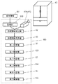
図1に示すように、市場1からリサイクル工場2へ冷蔵庫が回収される。回収された冷蔵庫は、工程10を経て、個体情報から処理情報が得られる。処理情報とは、冷蔵庫を解体するにあたり、使用されている材料に応じて処理工程が選択される場合に、選択される処理工程を識別するための情報である。
As shown in FIG. 1, the refrigerator is collected from the
まず、図2、図3に示すように、記憶部150には、冷蔵庫40の個体情報と関連付けられた、冷蔵庫40を解体するための処理情報151が予め記憶される(記憶する工程152)。記憶部150は、冷蔵庫の解体装置159に含まれる。個体情報読出工程30において、個体情報読出部41により、冷蔵庫40から個体情報が読み出される。処理情報取出工程31では、処理情報取出部42により、読み出された個体情報から冷蔵庫40を解体するための処理情報が取り出される。図2、図3、図5に示すように、処理情報表示工程32では、処理情報表示部43により、取り出された処理情報が処理情報表示材46を介して冷蔵庫40へ表示される。なお、冷蔵庫40がパレットなどに載置されて移動する場合、処理情報はパレットへ表示されても良い。あるいは、処理情報は、直接、冷蔵庫40へ印刷されても良い。
First, as shown in FIGS. 2 and 3, processing
図1、図8に示すように、第一判定工程11において、第一判定部56により、冷蔵庫40は表示された処理情報に基いて予備処理工程12と冷媒回収工程19、20とのいずれへ進められるか、が判定される。
As shown in FIGS. 1 and 8, in the
第一判定工程11による判定の結果、直接、冷媒回収工程19、20へ進められると判定された冷蔵庫40は、第一制御部153により、まず庫内部品が回収される庫内部品回収工程13へと進められる(工程156)。ここで、冷蔵庫内の棚や引出しなどの庫内部品が回収される。回収された庫内部品は、その材質ごとに庫内部品選別14、庫内部品破砕15され、再資源として出荷16される。
As a result of the determination in the
なお、「冷蔵庫40が、直接、冷媒回収工程19、20へ進められる」とは、予備処理工程12を経ることなく、冷媒回収工程19、20へ進められることをいう。予備処理工程12を経なければ、冷蔵庫40は、途中、他の工程を経由して冷媒回収工程19、20へ進められてもよい。
Note that “the
一方、第一判定工程11による判定の結果、予備処理工程12へ進められると判定された冷蔵庫40は、第一制御部153により、処理情報に基いて予備処理が施される予備処理工程12へ進められる(工程156)。
On the other hand, as a result of the determination in the
ここで、予備処理について説明する。本発明の実施の形態1において、予備処理の対象と位置付けられる機種は、断熱材へゲッター材が取り付けられる機種、圧縮機の取付け位置や圧縮機の取付け方が特徴的な機種、冷媒としてアンモニアが用いられる機種などである。 Here, the preliminary process will be described. In the first embodiment of the present invention, the model that is positioned as an object of the pretreatment includes a model in which the getter material is attached to the heat insulating material, a model in which the compressor mounting position and the compressor mounting method are characteristic, and ammonia as a refrigerant. The model used.
断熱材へゲッター材が取り付けられる機種は、冷蔵庫の筐体外部から筐体を成す壁面へ複数の孔が開けられる。ゲッター材が活性状態であれば、ゲッター材と水分とが反応して発熱する恐れがある。そこで、ゲッター材を大気と接触させることで、予めゲッター材の性質は活性状態から不活性状態へと変化される。このゲッター材の性質変化には約48時間を要する。よって、断熱材へゲッター材が混入される機種は、予備処理の対象とされる。 In the model in which the getter material is attached to the heat insulating material, a plurality of holes are opened from the outside of the refrigerator housing to the wall surface forming the housing. If the getter material is in an active state, the getter material and moisture may react to generate heat. Therefore, by bringing the getter material into contact with the atmosphere, the properties of the getter material are changed from the active state to the inactive state in advance. It takes about 48 hours to change the properties of the getter material. Therefore, a model in which the getter material is mixed into the heat insulating material is a target for preliminary processing.
圧縮機の取付け位置や圧縮機の取付け方が特徴的な機種としては、トップユニットと呼ばれる、圧縮機が冷蔵庫の上部に位置する機種がある。その他、特徴的な機種として、圧縮機と冷凍サイクルをなす配管との接続部分に鉄管が使用される機種や、圧縮機を冷蔵庫へかしめて固定される機種や、圧縮機を取り外す作業を行うにあたり、作業空間がないためにボルトやナットを緩める作業が行えない機種がある。 As a model characterized by the compressor mounting position and the compressor mounting method, there is a model called a top unit in which the compressor is located at the top of the refrigerator. In addition, as a characteristic model, a model in which an iron pipe is used for the connection part between the compressor and the piping forming the refrigeration cycle, a model in which the compressor is crimped to the refrigerator, and a work to remove the compressor are performed. There are models that cannot perform the work of loosening bolts and nuts because there is no working space.
圧縮機が冷蔵庫の上部に位置する機種は、冷蔵庫を立てた状態では圧縮機の取り外し作業がやり難い。そこで、予備処理工程12において、作業者が圧縮機を取り外し易い位置関係が構築される。作業者は、圧縮機の取り外し作業を効率よく行える。
With the model in which the compressor is located at the top of the refrigerator, it is difficult to remove the compressor when the refrigerator is standing. Therefore, in the
一般的に、圧縮機と冷凍サイクルをなす配管との接続部分には銅管が使用される。銅管は加工が容易なので、超音波溶着機やかしめ器を用いて、この接続部分の銅管が塞がれる。銅管は一定の幅を有するように塞がれる。あるいは、銅管は近接する二ヶ所が塞がれる。一定の幅を有して塞がれた銅管は、一定の幅の中心付近が切断される。あるいは、近接する二ヶ所が塞がれた銅管は、塞がれた二ヶ所を分断するように切断される。こうして、冷蔵庫の筐体側配管と圧縮機側配管の双方切断部分が塞がれた状態で、圧縮機が取り出される。 Generally, a copper pipe is used for a connection portion between a compressor and a pipe forming a refrigeration cycle. Since the copper tube is easy to process, the copper tube at this connecting portion is closed using an ultrasonic welding machine or a caulking device. The copper tube is closed to have a certain width. Alternatively, the copper tube is closed at two adjacent locations. The copper tube closed with a certain width is cut near the center of the certain width. Alternatively, a copper tube in which two adjacent places are closed is cut so as to divide the two closed places. Thus, the compressor is taken out in a state where both the cut portions of the refrigerator side piping and the compressor side piping are closed.
しかしながら、圧縮機と冷凍サイクルをなす配管との接続部分に鉄管が使用される機種は、配管の加工が容易ではなく、圧縮機の取り外しが困難となる。そこで、予備処理工程12では、鉄管用の専用かしめ器を用いて配管が近接する二ヶ所で塞がれる。近接する二ヶ所が塞がれた配管は、二ヶ所のかしめ部を分断するように切断される。その結果、冷蔵庫の筐体側配管と圧縮機側配管の双方切断部分が塞がれた状態で、圧縮機が取り外される。
However, in a model in which an iron pipe is used for a connection portion between a compressor and a pipe forming a refrigeration cycle, the pipe is not easily processed and the compressor is difficult to remove. Therefore, in the
圧縮機を冷蔵庫へかしめて固定される機種は、かしめを戻して圧縮機が取り外される。また、圧縮機を取り外す作業を行うにあたり、作業空間がないためにボルトやナットを緩める作業が行えない機種は、ボルトやナット周辺の部材を取り外すなどして作業空間が確保される。その後、ボルトやナットが取り外された後、圧縮機が取り外される。 For models in which the compressor is caulked and fixed, the caulking is returned and the compressor is removed. In addition, when the work for removing the compressor is performed, a model in which the work for loosening the bolts and nuts cannot be performed because there is no work space, the work space is secured by removing members around the bolts and nuts. Thereafter, after the bolts and nuts are removed, the compressor is removed.
冷媒としてアンモニアが用いられる機種は、専用工程が設けられる。冷媒としてアンモニアが用いられる機種は、この専用工程において解体処理が行われる。 A model that uses ammonia as a refrigerant is provided with a dedicated process. Models that use ammonia as a refrigerant are dismantled in this dedicated process.
以上のような予備処理が行われた後、これらの冷蔵庫は、庫内部品が回収される庫内部品回収工程13へ進められる。
After the preliminary processing as described above is performed, these refrigerators are advanced to the in-
なお、一部の機種については、圧縮機が取り外された状態で、庫内部品が回収される庫内部品回収工程13へ進められる。
For some models, the process proceeds to an in-house
次に、庫内部品が回収された冷蔵庫は、圧縮機が回収される圧縮機回収工程17へ進められる。具体的には、圧縮機と、冷凍サイクルを成す配管とが分離される。この結果、冷蔵庫から圧縮機が分離、回収される。
Next, the refrigerator from which the internal parts have been collected proceeds to the
図1、図8に示すように、冷媒が冷蔵庫40から回収される際、第二判定工程18では、第二判定部57により、表示された処理情報に基いて、冷蔵庫40から回収される冷媒が判定される。第二制御部154は、第二判定部57の判定結果に従って、冷蔵庫40から冷媒を回収する工程へ進めるように動作する(工程157)。
As shown in FIGS. 1 and 8, when the refrigerant is collected from the
冷媒の回収方法は、大きく二種類に大別される。フロンと可燃性冷媒であるイソブタンである。各種規制の取決めにより、フロンは、その組成ごとに回収容器であるボンベへ回収される。一方、イソブタンは、希釈して濃度が低下された後、大気中へ開放される。 There are two main types of refrigerant recovery methods. It is chlorofluorocarbon and isobutane which is a flammable refrigerant. According to various regulatory arrangements, chlorofluorocarbons are collected in a cylinder, which is a collection container, for each composition. On the other hand, isobutane is released into the atmosphere after being diluted to lower its concentration.
冷蔵庫から圧縮機が分離される。冷蔵庫本体内に残存する冷媒と、圧縮機に残存する冷媒とに分けて冷媒が回収される。冷蔵庫本体内に残存する冷媒は極めて少量のため、短時間で回収される。一方、圧縮機内に残存する冷媒は、大量かつ潤滑油に溶出しているものもある。圧縮機内に残存する冷媒が、全て回収されるには、相応の時間が必要となる。 The compressor is separated from the refrigerator. The refrigerant is recovered by dividing it into a refrigerant remaining in the refrigerator main body and a refrigerant remaining in the compressor. Since the refrigerant remaining in the refrigerator main body is extremely small, it is recovered in a short time. On the other hand, a large amount of refrigerant remaining in the compressor is eluted in the lubricating oil. Appropriate time is required to recover all the refrigerant remaining in the compressor.
そこで、本発明における実施の形態1のように、圧縮機が冷蔵庫から分離される。冷蔵庫と圧縮機から別々に冷媒が回収される。この結果、冷蔵庫の筐体をなす部分の解体作業は、円滑に進められる。
Then, like
なお、上記説明では、冷蔵庫の筐体と圧縮機とを分離した後、回収される冷媒が各々、第二判定工程18で判定された。回収される冷媒は、この第二判定工程18で一括して判定された後、冷蔵庫の筐体と圧縮機に分けるよう、処理されてもよい(図1中、一点鎖線160で示すフロー)。
In the above description, the refrigerant collected after the refrigerator casing and the compressor are separated from each other is determined in the
図1に示すように、冷媒が回収された冷蔵庫は、残部品回収工程22において配管類やプリント基板などの部品が回収される。この結果、冷蔵庫は筐体のみとなる。
As shown in FIG. 1, in the refrigerator from which the refrigerant is recovered, components such as piping and a printed circuit board are recovered in the remaining
一方、冷媒が回収された圧縮機は分解され(圧縮機分解工程21)、圧縮機を構成する材料ごとに仕分けられて再資源として出荷16される。 On the other hand, the compressor from which the refrigerant has been recovered is decomposed (compressor disassembling step 21), sorted for each material constituting the compressor, and shipped 16 as a resource.
こうして第二判定工程18の判定結果に従い、冷媒が冷蔵庫から回収された後、冷蔵庫は第三判定工程23へと進められる。第三判定工程23では、第三判定部59(図11)により、処理情報に基いて冷蔵庫40が破砕工程25と待機工程24とのいずれへ進められるかを判定する(工程158)。
Thus, after the refrigerant is recovered from the refrigerator according to the determination result of the
本発明の実施の形態1において、筐体のみとなった冷蔵庫は、表示された処理情報により、使用している断熱材ごとに仕分けがなされる。具体的には、断熱材に用いられている発泡ガスの種類により、大きく2つに分けられる。つまり、フロンのように回収を必要とするガス種と、シクロペンタンのように大気への希釈、開放を必要とするガス種である。
In
図1、図11に示すように、第三判定工程23において、第三判定部59により、冷蔵庫40は、直接、破砕工程25へ進められて破砕されるか、あるいは、待機工程24へ進められるか、判定される(工程158)。第三制御部155は、第三判定部59の判定結果に従って、冷蔵庫40を破砕工程へ進める、あるいは、冷蔵庫40を待機工程24を介して破砕工程25へ進めるように動作する(工程158)。
As shown in FIGS. 1 and 11, in the
待機工程24へ進められた冷蔵庫40は、待機する冷蔵庫40群の台数が所定台数となった後、破砕工程25へ進められて破砕される。
The
これら待機工程24と破砕工程25について、詳細に説明する。
The
上述したように、断熱材に用いられる発泡ガスの種類により、筐体の破砕方法は大きく異なる。フロンが用いられる断熱材(以下、「フロン系断熱材」と記す。)の場合、各種規制の要請により、フロンが大気中へ放出されないよう、破砕室は密閉される。これに対し、シクロペンタンが用いられる断熱材(以下、「シクロペンタン系断熱材」と記す。)の場合、作業の安全性確保の観点より、シクロペンタンが大気で希釈された後、大気中へ開放される。 As described above, the method for crushing the housing varies greatly depending on the type of foaming gas used for the heat insulating material. In the case of a heat insulating material using CFC (hereinafter referred to as “CFC-based heat insulating material”), the crushing chamber is sealed so that CFC is not released into the atmosphere due to various regulatory requirements. On the other hand, in the case of a heat insulating material using cyclopentane (hereinafter referred to as “cyclopentane-based heat insulating material”), from the viewpoint of ensuring work safety, the cyclopentane is diluted in the air and then into the air. Opened.
この相反する作業が同一工程で行われる場合、使用される設備は切換作業が必要となる。この設備の切換作業が1台ごとに行われると、極めて作業効率が悪くなる。そこで本発明の実施の形態1では、同一設備を使用する冷蔵庫40の筐体が、所定台数となるまで蓄積されるのを待って、設備の切換が行われる少ロット切換方法が採用される。
When these conflicting operations are performed in the same process, the equipment used needs to be switched. If this equipment switching operation is performed for each unit, work efficiency is extremely deteriorated. Therefore, in the first embodiment of the present invention, a small lot switching method is adopted in which the facilities are switched after waiting for the housings of the
具体例として、破砕工程25において、フロン系断熱材が破砕される場合、第三判定工程23へフロン系断熱材が用いられた冷蔵庫が進められると、この冷蔵庫は破砕工程25へと進められる。一方、第三判定工程23へシクロペンタン系断熱材が用いられた冷蔵庫が進められると、この冷蔵庫は待機工程24へと進められる。このとき、破砕工程25では、作業室が密閉され、フロンガスを回収しながら冷蔵庫の筐体が破砕される。
As a specific example, in the crushing
このような作業が行われた結果、所定台数、例えばシクロペンタン系断熱材が用いられた冷蔵庫が60台程度蓄積されると、第三判定工程23において、つぎの工程切替えが行われる。つまり、シクロペンタン系断熱材が用いられた冷蔵庫は、破砕工程25へ進められる。フロン系断熱材が用いられた冷蔵庫は、待機工程24へ進められる。
As a result of such operations, when about 60 refrigerators using a predetermined number of, for example, cyclopentane-based heat insulating materials are accumulated, the next process switching is performed in the
その後、蓄積されたシクロペンタン系断熱材が用いられた冷蔵庫は、待機工程24から全て取出される。そして、待機工程24に蓄積された冷蔵庫が、全てフロン系断熱材が用いられた冷蔵庫となる。このとき、第三判定工程23において、つぎの工程切替えが行われる。つまり、フロン系断熱材が用いられた冷蔵庫は、破砕工程25へ進められる。シクロペンタン系断熱材が用いられた冷蔵庫は、待機工程24へと進められる。
Thereafter, all the refrigerators using the accumulated cyclopentane heat insulating material are taken out from the
このような少ロット切替方法が採用されると、ラインの切替回数が最小限に抑えられるため、効率よく冷蔵庫が解体処理される。 When such a small lot switching method is adopted, the number of line switching times can be minimized, so that the refrigerator is efficiently disassembled.
こうして破砕された冷蔵庫は、従来から使用されている風力選別機や磁力選別機などで材料ごとに選別工程26で選別され、再資源として出荷16される。
The crushed refrigerator is sorted in the sorting
要部について、詳述する。 The main part will be described in detail.
冷蔵庫の処理情報が取り出されるためには、以下の作業が必要となる。 In order to extract the processing information of the refrigerator, the following work is required.
まず第1の作業として、作業対象となる冷蔵庫の機種が特定される個体情報の入手である。具体例として、図3、図4に示すように、冷蔵庫40は、冷蔵庫40の外観映像から機種が特定される。あるいは、冷蔵庫40は、冷蔵庫40に貼付された品番を読み取ることで機種が特定される。品番を読み取るほうが、より正確に冷蔵庫40の機種を特定できる。この作業において、個体情報読出部41として、冷蔵庫40の外観を写すカメラ41Aや、品番を読み取るスキャナー41Bが用いられる。読み出された個体情報は、処理情報取出部42へ送られる。
First, as a first work, acquisition of individual information for specifying a model of a refrigerator as a work target. As a specific example, as shown in FIGS. 3 and 4, the model of the
ところで、冷蔵庫40が解体されるリサイクルの現場には、多様なメーカーが長期間に亘って製造、販売してきた多種多様な冷蔵庫40が持ち込まれる。当然、各メーカーで付与された品番はメーカーごとに異なる。そこで、撮影された冷蔵庫40の外観映像や読み取られた冷蔵庫40の品番などの個体情報から、各冷蔵庫40を解体処理するための処理情報を効率よく取出せるように整えることが重要となる。
By the way, a variety of
第2の作業は、処理情報のデータベース化である。 The second task is to create a database of processing information.
効率よく冷蔵庫を解体処理するためには、処理作業に関する情報を蓄積し、処理情報として有効に活用することが重要である。 In order to efficiently disassemble the refrigerator, it is important to accumulate information on processing work and effectively use it as processing information.
上述したように、異なる処理方法から最適な処理方法を選択するためには、少なくとも冷蔵庫に使用される断熱材の種類と、冷蔵庫に使用される冷媒の種類とを表す情報が必須となる。 As described above, in order to select an optimal processing method from different processing methods, information indicating at least the type of heat insulating material used in the refrigerator and the type of refrigerant used in the refrigerator is essential.
さらに、処理情報として、予備処理の対象としている圧縮機の取付け位置や、圧縮機の取付け方を有することも必要である。 Furthermore, as processing information, it is also necessary to have the mounting position of the compressor to be subjected to the preliminary processing and the mounting method of the compressor.
なお、処理情報に紐付けされる情報は、冷蔵庫の処理に必要となる項目が発生するたびに適宜、追加すればよい。 In addition, what is necessary is just to add the information linked | related with process information suitably, whenever the item required for the process of a refrigerator generate | occur | produces.
このように、冷蔵庫の個体情報に対して、冷蔵庫が解体されるために必要となる処理情報が紐付けされたデータベースが構築される。 In this way, a database is constructed in which processing information necessary for disassembling the refrigerator is associated with the individual information of the refrigerator.
第3の作業は、個体情報と処理情報との速やかな結び付けである。 The third operation is a quick connection between the individual information and the processing information.
具体的には、第1の作業で得られた個体情報から、第2の作業で蓄積された処理情報が効率よく取出される処理情報取出部42を構築することである。詳細は、本発明の実施の形態2で説明する。
Specifically, the processing
第4の作業として、構築されたデータベースから精度よく取り出された処理情報が、各冷蔵庫へ表示されることが必要である。図5、図6は、処理情報を示す処理情報表示材46、46Aの一例である。処理情報表示材46、46Aは、処理情報表示部43により、作成される。
As a fourth operation, it is necessary that the processing information accurately extracted from the constructed database is displayed on each refrigerator. 5 and 6 are examples of the processing
図5中、44は冷媒の種類を示し、45は断熱材の種類を示す。この冷媒の種類44は、その種類ごとに異なる色で表示される。あるいは、図6中のこの冷媒の種類47は、その種類ごとに異なる記号や図形で表示される。これらの色や記号、図形と、冷媒が回収される工程で使用される治具との対応関係が一目で分かるように表示される。具体的には、R12が黄色で表示される場合、冷媒を回収する治具として黄色のホースが用いられたり、黄色で印をされたボンベが用いられたりする。同様に、R22は黒色で表示される。R134aは青色で表示される。R502は緑色で表示される。イソブタンは赤色で表示される。こうすれば、経験が浅い作業者であっても、使用する治具が一目で分かる。熟練の作業者であれば、使用する治具の取り違いを防ぐことが期待できる。また、作業者は、多数存在する治具の中から必要なものを抽出し易くなる。よって、作業効率も向上する。図6に示すように、冷媒を区別する表示は、記号や図形を用いてもよい。冷媒を区別する表示は、これら記号や図形を冷蔵庫や治具へ目立つように取り付けられる。例えば、R12は三角形で表示される。R22は星形で表示される。R134aは四角形で表示される。
In FIG. 5, 44 shows the kind of refrigerant | coolant and 45 shows the kind of heat insulating material. The
同様に、断熱材の種類は、バーコード45(図5)や、QRコード48(図6)で示される。 Similarly, the type of heat insulating material is indicated by a bar code 45 (FIG. 5) or a QR code 48 (FIG. 6).
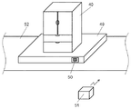
その他、処理情報表示材46、46Aの他の例として、図7に示すように、ICチップ50を用いることも可能である。例えば、処理情報がICチップ50へ書き込まれる。図7に示すように、このICチップ50が、冷蔵庫40を搬送するパレット49へ取り付けられる。冷蔵庫40の解体工程には、要所にICチップ50へ書き込まれたデータを読み取る読取機51が設けられる。そして、冷蔵庫40を載せたパレット49が各処理工程へ近づいて来たときに、読取機51は必要なデータを読み取る。読み取られたデータは、読取機51にその内容が表示される。ICチップ50は繰り返し使用できるため、経済性に富む。
In addition, as another example of the processing
あるいは、処理情報を直接、冷蔵庫へ印刷してもよい。 Alternatively, the processing information may be printed directly on the refrigerator.
つまり、取り出された処理情報は、処理情報表示部43により、直接、冷蔵庫へ表示されても良く、処理情報表示材46、46A、ICチップ50などを介して間接的に冷蔵庫へ表示されても良い。
That is, the extracted processing information may be directly displayed on the refrigerator by the processing
つぎに、冷媒を回収する工程について、説明する。 Next, the step of recovering the refrigerant will be described.
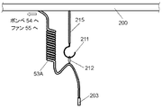
図8は、第一判定部56で上記第一判定工程11を経て、冷媒回収工程19、20へと進められた冷蔵庫40を示す。本実施の形態1では、冷蔵庫40が搬送されるコンベア52を一本とし、冷媒を回収する治具を冷媒の種類ごとに準備している。冷媒を回収する治具とは、連通路であるホース53と、回収容器であるボンベ54と、攪拌部であるファン55である。なお、ホース53、ボンベ54、ファン55を合せて治具53、54、55と記すこともある。この工程を用いて、第二判定部57の結果が第二制御部154へ反映される。すなわち、冷媒を回収する治具53、54、55には、冷媒の種類に応じた異なる色や記号、図形が表示される。第二制御部154は、冷媒の種類に応じた異なる色や記号、図形を作業者へ知らせる。この結果、経験が浅い作業者であっても、使用する治具が一目で分かる。熟練の作業者であれば、使用する治具の取り違いを防ぐことができる。また、作業者は、多数存在する治具の中から必要なものを抽出し易くなる。よって、作業効率が向上するという効果を奏する。しかも、本発明の冷蔵庫の解体装置は、敷設されるコンベア52が一本となるため、冷蔵庫40の解体装置が設置される面積も少なくなる。
FIG. 8 shows the
これに対し、図9に示す工程は、冷媒の種類ごとにコンベア52が敷設される。本工程は、冷媒を回収する治具53、54、55は、各コンベア52へ設けられる。すなわち、冷媒を回収する治具53、54、55は、冷媒の種類だけ必要となる。この場合、冷蔵庫40を解体する設備が設置される面積は多くなる。しかし、図9に示す工程を用いれば、冷蔵庫40は、第二制御部154により、第二判定部57の判定結果に応じたコンベア52へ進められる。よって、本工程は、作業者による治具53、54、55の取り違えを防ぐことができる。また本工程は、同時に多数の冷蔵庫40を並行して処理できるという利点がある。
In contrast, in the process shown in FIG. 9, the
図10は、冷媒が圧縮機58から回収される工程である。複数の冷蔵庫から、同種の冷媒が用いられた圧縮機58が連続して回収されることは稀である。また、各圧縮機58から冷媒が回収されるには、相応の時間が必要とされる。よって、回収された圧縮機58は、適宜、冷媒の種類ごとに仕分けられた作業台に集められる。そして、順次、圧縮機58から冷媒を回収することが効率的である。
FIG. 10 is a process in which the refrigerant is recovered from the
つぎに、第三判定部59を用いた第三判定工程から破砕工程について、図1および、図11から図15を用いて説明する。
Next, the third determination process to the crushing process using the
冷媒が回収された冷蔵庫40は、第三判定部59による上記第三判定工程23を経た結果、第三制御部155により、つぎの二つの場合に仕分けられる。ひとつの場合は、冷蔵庫40は、冷蔵庫40が破砕される破砕室60へ直接進められる。もうひとつの場合は、冷蔵庫40は、待機工程24を形成する待機位置61へ進められる。説明の都合上、フロン系断熱材が用いられた冷蔵庫は40Aとする。シクロペンタン系断熱材が用いられた冷蔵庫は40Bとする。
The
図11中、フロン系断熱材が用いられた冷蔵庫40Aは破砕室60へ進められる。シクロペンタン系断熱材が用いられた冷蔵庫40Bは待機位置61へ進められる。このとき、破砕室60に設けられたファン62は停止しているため、フロンは回収容器であるボンベ63へ回収される。なお、回収容器であるボンベ63は、ドラム缶などの容器を用いてもよい。
In FIG. 11, the
作業が進み、待機位置61へ蓄積される冷蔵庫40Bが所定台数まで蓄積される。本発明の実施の形態1では、所定台数を60台と設定している(図12)。
Work progresses and the
この結果、第三制御部155は、待機位置61において待機していた冷蔵庫40Bを破砕室60へ送り出す。第三制御部155は、冷蔵庫40Aを待機位置61へ進める。もし、冷媒回収工程19から冷蔵庫40Bが送られてきた場合、この冷蔵庫40Bは、第三制御部155により、直接、破砕室60へ進められる。破砕室60は、フロンをボンベ63へ回収する動作が停止される。破砕室60に設けられたファン62は、シクロペンタン等を大気中へ開放するように動作される(図13)。
As a result, the
作業が進み、待機位置61に蓄積された冷蔵庫40Bが全て送り出される。待機位置61には、冷蔵庫40Aが60台蓄積される(図14)。
Work progresses and all the
この結果、再び第三制御部155により、冷蔵庫40Aは、直接、破砕室60へ進められる。また、第三制御部155は、冷蔵庫40Bを待機位置61へ進めるように動作する。
As a result, the
このような少ロット切替方法が採用されると、破砕室60の動作環境の切替回数は、最小限に抑えられる。よって、少ロット切替方法が採用されると、冷蔵庫40A、40Bは、効率よく解体処理される。
When such a small lot switching method is adopted, the number of times of switching of the operating environment of the crushing
以上の説明から明らかなように、本発明の実施の形態1に係る冷蔵庫の解体方法および解体装置を用いれば、リサイクル工場へ入荷した順番に冷蔵庫が解体処理される。よって、従来のロット処理で必要であった処理待ち冷蔵庫を保管する空間が不要となる。換言すれば、冷蔵庫の解体設備が敷設される延べ床面積は、少なくなる。
As is clear from the above description, if the refrigerator disassembly method and disassembly apparatus according to
また、冷蔵庫の処理鮮度が向上するため、リサイクル工場における冷蔵庫の解体速度が速くなる。ロット処理を切替える際に生じていた切替ロスは、発生が防止される。また、保管場所から処理工程へ処理対象の冷蔵庫を移動するために生じていた移動ロスは、発生が防止される。つまり、リサイクル工場における冷蔵庫の解体処理能力は向上する。 Moreover, since the processing freshness of a refrigerator improves, the disassembly speed of the refrigerator in a recycling factory becomes quick. The switching loss that has occurred when the lot processing is switched is prevented from occurring. Further, the movement loss that has occurred due to the movement of the refrigerator to be processed from the storage location to the processing step is prevented. That is, the dismantling capacity of the refrigerator in the recycling factory is improved.
すなわち、本発明の実施の形態1に係る冷蔵庫の解体方法および解体装置を用いれば、空間的要素と時間的要素の改善が図られる。
That is, if the refrigerator dismantling method and dismantling apparatus according to
特に冷媒回収については、大気中への希釈、開放が必要とされる可燃性冷媒と、その種類ごとに回収が必要とされるフロンとが取扱われる。冷媒回収を行うにあたり、経験が浅い作業者でも一目で取扱い方法が理解できるように、冷媒の種類に応じて使用する治具が色や形状で区別される。あるいは、ICチップなどを用いて、冷蔵庫を解体する方法が、機械的に判定されることにより、作業を安全かつ精度よく行うことが可能となる。 In particular, with regard to refrigerant recovery, combustible refrigerants that require dilution and release into the atmosphere and chlorofluorocarbons that require recovery for each type are handled. When recovering the refrigerant, jigs used according to the type of refrigerant are distinguished by color and shape so that even an inexperienced operator can understand the handling method at a glance. Alternatively, the method of disassembling the refrigerator using an IC chip or the like is mechanically determined, so that work can be performed safely and accurately.
なお、上記実施の形態1は、冷蔵庫の解体処理について説明した。実施の形態1は、他の電化製品、例えば、テレビ受像機や空気調和装置、洗濯機などにも応用できる。その場合、本実施の形態1にて採用した第一判定部から第三判定部において判定する項目や基準は、対象となる電化製品に応じて適宜、設定される。
In addition, the said
例えば、テレビ受像機の場合、第一判定部は画像を表示する方法で判定してもよい。具体的な指標は、ブラウン管表示装置、プラズマ表示装置、液晶表示装置等が考えられる。 For example, in the case of a television receiver, the first determination unit may determine by a method of displaying an image. Specific indicators include cathode ray tube display devices, plasma display devices, liquid crystal display devices, and the like.
第二判定部の判定基準は、各表示装置の表示部をなすガラス材料の種類やその切断方法が考えられる。あるいは、第二判定部の判定基準は、ハードディスクをはじめとする付加機能の搭載有無としてもよい。上記設定とすれば、同一の設備を用いて、入荷順にブラウン管を用いたテレビ受像機等が解体処理される。 As the determination criterion of the second determination unit, the type of glass material forming the display unit of each display device and the cutting method thereof can be considered. Alternatively, the determination criterion of the second determination unit may be whether or not an additional function such as a hard disk is installed. With the above setting, a television receiver or the like using a cathode ray tube is disassembled in the order of arrival using the same equipment.
また、空気調和装置の場合、上述した冷蔵庫と同様に、冷媒の種類を判定基準としてもよい。上記設定とすれば、冷蔵庫と同様に、同一設備で、入荷順に空気調和装置が解体処理される。 In the case of an air conditioner, the type of refrigerant may be used as a criterion for determination as in the above-described refrigerator. If it is the said setting, an air conditioning apparatus will be disassembled in the order of arrival with the same installation similarly to a refrigerator.
また、洗濯機の場合、判定基準は、ヒートポンプユニットやイオン発生器を搭載したものなど、高機能の有無としてもよい。上記設定とすれば、同一設備で、入荷順に洗濯機が解体処理される。 In the case of a washing machine, the determination criterion may be the presence or absence of high functionality such as a heat pump unit or an ion generator. If it is the said setting, a washing machine will be dismantled in order of arrival with the same equipment.
判定基準は、上記記載に囚われることなく、適宜、対象となる電化製品に応じて設定されればよい。また、これらを対象とする処理情報も、適宜、対象となる電化製品に応じて設定されればよい。 The determination criteria may be appropriately set according to the target appliance without being bound by the above description. Also, the processing information for these may be set as appropriate according to the target appliance.
(実施の形態2)
以下、本発明の実施の形態2における文字列抽出装置および文字列抽出方法について、図面を参照しながら説明する。(Embodiment 2)
Hereinafter, a character string extraction device and a character string extraction method according to
まず、図16に本発明の実施の形態2の文字列抽出装置のブロック図を示す。なお、図16を用いて、文字列抽出方法のフローも併せて説明する。 First, FIG. 16 shows a block diagram of the character string extraction apparatus according to the second embodiment of the present invention. The flow of the character string extraction method will also be described with reference to FIG.
図中、画像入力部70によって、廃電化製品である冷蔵庫に表示された品番が読み取られる。画像入力部70は、スキャナーで実現できる。演算部71によって、画像入力部70で読み取られた画像情報から後段で詳述する候補文字列が算出される。登録部72には、演算部71で用いられるデータが登録される。表示部73によって、演算部71で算出された結果が表示される。表示部73は、ディスプレイで実現できる。例えば、演算部71が一体型のパーソナルコンピュータで構成される場合、表示部73は、演算部71と一体で構成される。入力部74によって、演算部71で算出された結果を、出力部75で出力するための入力指示が行われる。出力部75は、プリンターや、ICチップ等の記録媒体への書き込み装置で実現できる。
In the figure, the product number displayed on the refrigerator, which is a waste electrical appliance, is read by the
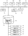
文字列抽出装置を実現するハードウェア構成を図17に示す。図に示すように、本発明の実施の形態2に係る文字列抽出装置は、CPU101と、ROM102と、RAM103と、スキャナーで構成される画像入力部70と、表示部73と、ハードディスク部(図中、「HDD」と記す。)104と、マウス、キーボードなどで構成される入力部74と、プリンターで構成される出力部75などを備える。
A hardware configuration for realizing the character string extraction apparatus is shown in FIG. As shown in the figure, the character string extraction apparatus according to the second embodiment of the present invention includes a
CPU101は、プログラムに従って動作する。ROM102は、基本的なプログラムを記憶する。RAM103は、その他のプログラムやデータを一時的に記憶する。スキャナーは、画像情報を読み取る画像入力部70である。ハードディスク部104は、各種プログラムやデータを記憶する。入力部74は、キーボードやマウスなどである。出力部75は、プリンターやICチップへの書き込み装置などである。
The
ハードディスク部104は、機種品番別基礎データを記憶したデータベース(図中、「DB」と記す。)105を有する。データベース105は、各種マスタを有する。各種マスタの一例として、以下のものが挙げられる。冷蔵庫を製造したメーカーを記憶しているメーカーマスタ106。冷蔵庫に使用される冷媒を記憶する冷媒マスタ107。冷蔵庫に使用される断熱材を記憶する断熱材マスタ108。冷蔵庫に使用される圧縮機を記憶する圧縮機マスタ109。冷蔵庫が必要とする実施の形態1で例示した各種予備処理を記憶する予備処理マスタ110。
The
以上の構成からなる文字列抽出装置の動作について、主に、図16、図24A、図24Bのブロック図と、図26A、図26Bのフローチャートとを用いて説明する。 The operation of the character string extraction apparatus configured as described above will be described mainly with reference to the block diagrams of FIGS. 16, 24A, and 24B and the flowcharts of FIGS. 26A and 26B.
(事前準備について)
まず、事前準備として、置換情報登録工程と候補文字データ登録工程とが実施される。置換情報登録工程において、置換情報80Aが置換情報登録部80へ登録される。候補文字データ登録工程において、候補文字データ123が候補文字データ登録部81へ登録される。(Preparation)
First, as a preliminary preparation, a replacement information registration step and a candidate character data registration step are performed. In the replacement information registration step,
置換情報登録工程において、誤認識が予想される文字情報について、特定文字を指定文字へと置換するための置換情報80Aが、予め置換情報登録部80へ登録される。
In the replacement information registration step,
指定文字とは、品番を読み取る対象となる電化製品で通常使用される文字をいう。一般的に、アルファベット、特に大文字のアルファベットとアラビア数字とがよく用いられる。さらに、「―(ハイフン)」を代表とする大文字のアルファベットとアラビア数字とを結び付ける文字もよく用いられる。 Designated characters refer to characters that are normally used in electrical appliances from which product numbers are read. In general, alphabets, particularly capital letters and Arabic numerals are often used. In addition, letters that connect uppercase alphabets such as “-(hyphen)” and Arabic numerals are often used.
特定文字とは、OCR(光学的文字読取装置)等で画像情報から文字情報を読み取る際、指定文字と比較して「明らかに間違っている文字」、「明らかに間違いやすい文字」、「間違いやすいが、どちらか判らない文字」をいう。 The specific characters are “obviously wrong characters”, “obviously wrong characters”, “easy to make mistakes” when reading character information from image information with an OCR (optical character reader) or the like. "I don't know which".
指定文字と特定文字とは、対象となる電化製品によって異なる。この違いには、地域性も含まれる。指定文字として、ギリシャ文字やギリシャ数字、アラビア文字あるいはハングル文字等が用いられることもある。指定文字と特定文字とは、予め対象となる電化製品を調べれば、その範囲が特定される。 The designated character and the specific character differ depending on the target electrical appliance. This difference includes regional characteristics. Greek letters, Greek numerals, Arabic letters, Korean letters, etc. may be used as the designated characters. The range of the designated character and the specific character is specified if the target electrical appliance is examined in advance.
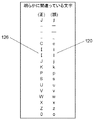
本発明の実施の形態2において、冷蔵庫を対象製品とする。この場合、「明らかに間違っている文字」(120)、「明らかに間違いやすい文字」(121)、「間違いやすいが、どちらか判らない文字」(122)が、特定文字と位置づけられる。そして、これらの特定文字120、121、122に対する指定文字126が、予め定義される。その内容を、図18、図19、図20に示す。
In
これら指定文字126が定義付けされると、最終的に得たい候補文字列127(図21)に対して、指定文字126を用いた場合に想定される候補文字データ123が導き出される。この想定される候補文字データ123の一例を、図21に示す。候補文字データ登録工程において、これら候補文字データ123が、予め候補文字データ登録部81へ登録される。
When these designated
(一次検索について)
つぎに、廃冷蔵庫に表示された品番から候補文字列を抽出する手順について説明する。(About primary search)
Next, a procedure for extracting candidate character strings from the product numbers displayed on the waste refrigerator will be described.
画像情報変換工程において、図16に示す画像入力部70で読み取られた画像情報は、画像情報変換部82によって文字情報へ変換される。図26Aに示すように、文字情報にスペースが含まれている場合、スペースは削除される(S1)。文字情報置換工程において、画像情報変換部82によって変換された文字情報の中に特定文字120、121、122が含まれている場合、特定文字120、121、122は、文字情報置換部83によって指定文字126へ置換される。また、文字情報置換工程において、画像情報変換部82によって変換された文字情報の中に特定文字120、121、122が含まれていない場合、変換された文字情報は、文字情報置換部83によって読取文字データと位置付けられる(S2、S3)。
In the image information conversion step, the image information read by the
検索文字生成工程において、読取文字データの所定文字は、検索文字生成部84によって特殊文字へ置換される(S4)。併せて、検索文字生成工程において、特殊文字が連続する場合、連続する特殊文字群は、検索文字生成部84によって一文字の特殊文字へさらに置換される。検索文字生成工程において、読取文字データから検索文字データが生成される(S5)。
In the search character generation step, the predetermined character of the read character data is replaced with a special character by the search character generation unit 84 (S4). In addition, in the search character generation step, when the special characters are continuous, the continuous special character group is further replaced with one special character by the search
所定文字とは、主に指定文字以外を指す。上述したように、予め対象となる電化製品を調べれば、指定文字には含まれない範囲が見出される。 The predetermined character mainly refers to a character other than the designated character. As described above, if a target electrical appliance is examined in advance, a range not included in the designated character is found.
本発明の実施の形態2において、廃冷蔵庫を対象製品とした場合、「英数()+−/.」以外は、所定文字と位置付けられる。本願の出願人が評価した結果、廃冷蔵庫を対象製品とした場合、漢字やカタカナ、ひらがなを用いた品番を見出すことがなかった。そこで、アルファベットの大文字とアラビア数字を中心として指定文字が設定された。これら所定文字を置換する特殊文字、いわゆるワイルドカードとして「%」や「*」が用いられる。 In the second embodiment of the present invention, when a waste refrigerator is a target product, the characters other than “alphanumeric () + − /.” Are positioned as predetermined characters. As a result of evaluation by the applicant of the present application, when a waste refrigerator was used as a target product, a product number using kanji, katakana or hiragana was not found. Therefore, the designated characters were set around the capital letters of the alphabet and Arabic numerals. "%" Or "*" is used as a special character for replacing these predetermined characters, a so-called wild card.
第一比較工程において、検索文字データと候補文字データとが、第一比較部85によって比較される(S6)。比較された結果(S7)、検索文字データと一致する候補文字データが存在する場合、候補文字データに対応する候補文字列が、候補文字列出力部86によって抽出される。
In the first comparison step, the search character data and the candidate character data are compared by the first comparison unit 85 (S6). As a result of the comparison (S7), if there is candidate character data that matches the search character data, a candidate character string corresponding to the candidate character data is extracted by the candidate character
こうして抽出された候補文字列は、候補文字列出力部86から表示部73へ表示される。図22に、候補文字列124の一例を示す。
The candidate character string extracted in this way is displayed on the
作業者が入力部74を操作することで、表示部73に示された候補文字列124から対象となる品番125が選択される。入力部74としてタッチパネル式のディスプレイが用いられる場合、このディスプレイは入力部74と表示部73とを兼用する。その結果、選択された品番125は処理情報とともに出力部75へ出力される。
When the operator operates the
出力部75から、図5、図6に示すような、処理情報表示部43、46が出力される。なお、この処理情報表示部43、46に代えて、再利用可能な記録媒体へ必要事項を記憶したものを出力してもよい。再利用可能な記録媒体として、ICチップ50等が利用できる。
Processing
なお、事前準備として上述した置換情報登録工程と候補文字データ登録工程とは、廃冷蔵庫以外の電化製品、テレビ受像機や空気調和装置、洗濯機等へも同様の内容を援用できる。 The replacement information registration step and the candidate character data registration step described above as pre-preparation can be applied to electric appliances other than the waste refrigerator, a television receiver, an air conditioner, a washing machine, and the like.
また、置換情報登録部80と候補文字データ登録部81へ登録される内容が、適宜、更新されると、より検索精度は向上する。
In addition, when the contents registered in the replacement
誤認識が予想される文字の範囲は、廃棄対象となる電化製品で採用される文字により定められる。 The range of characters that are expected to be misrecognized is determined by the characters that are adopted by the appliances to be discarded.
(一次検索の具体例について)
一次検索の具体例について、さらに説明する。(Specific examples of primary search)
A specific example of the primary search will be further described.
画像入力部70で読み取られた画像情報は、画像情報変換部82を介して文字情報へ変換される。変換された文字情報130を図23に示す。
The image information read by the
変換された文字情報130にはスペースが含まれている。そこで、後述する変換を容易にするため、文字情報130からスペースが削除される。スペースが削除された文字情報131には、図18、図19に示す特定文字120、121([明らかに間違っている文字]、[明らかに間違いやすい文字])が含まれる。よって、文字情報131は、「〜」を「−」へ、「o」を「0」へ置換される。この結果が、読取文字データ132となる。
The converted
検索文字生成工程において、読取文字データ132の所定文字が特殊文字へ置換される。併せて、検索文字生成工程において、特殊文字が連続する場合、連続する特殊文字群は、一文字の特殊文字へさらに置換される。検索文字生成工程において、読取文字データから検索文字データ133が生成される。本実施の形態2において、特殊文字は「%」が用いられる。
In the search character generation step, a predetermined character in the read
第一比較工程において、検索文字データ133と候補文字データとが比較される。比較された結果、検索文字データ133と一致する候補文字データが存在する場合、候補文字データに対応する候補文字列134が、候補文字列出力部86によって抽出される。
In the first comparison step, the
比較された結果、候補文字列134として「NR−201TR」が得られたため、検索は終了される。
As a result of the comparison, “NR-201TR” is obtained as the
(二次検索について)
もし、第一比較工程において、検索文字データと一致する候補文字データが存在しない場合、図24に示すブロック図に基づいて、次のフローが行われる。(About secondary search)
If there is no candidate character data that matches the search character data in the first comparison step, the following flow is performed based on the block diagram shown in FIG.
まず、第一比較部85における第一比較工程の結果(S7)を受けて、特殊文字付検索文字生成工程において、検索文字データから特殊文字付検索文字データが、特殊文字付検索文字生成部87によって生成される(S11)。特殊文字付検索文字データとは、検索文字データの前後(両端)へ特殊文字が付加されたものである。もし、特殊文字が連続する場合は、連続する特殊文字群を一文字の特殊文字としてさらに置換された後、検索文字データから特殊文字付検索文字データが生成される。
First, in response to the result (S7) of the first comparison step in the
第二比較工程において、特殊文字付検索文字データと候補文字データとが、第二比較部88によって比較される。すなわち、検索が実行される(S12)。比較された結果(S13)、特殊文字付検索文字データと一致する候補文字データが存在しない場合、特殊文字付検索文字データから付加された特殊文字に隣接する前後一文字が削除されたものが、新たな検索文字データと位置付けられる(S14)。そして、上述した特殊文字付検索文字生成工程が繰り返されて、新たな特殊文字付検索文字データが生成される。
In the second comparison step, the search character data with special characters and the candidate character data are compared by the
この特殊文字付検索文字生成工程は、新たな検索文字データが2文字未満となるまで繰り返される(S15)。その理由は、つぎの2点に対応するためである。すなわち、読み取られた画像情報から生成される読取文字データの桁数は一定ではない。しかも、生成される読取文字データの中心となる桁が予め定められていない。 This search character generation process with special characters is repeated until new search character data becomes less than two characters (S15). The reason is to deal with the following two points. That is, the number of digits of the read character data generated from the read image information is not constant. In addition, the digit that becomes the center of the generated read character data is not predetermined.
そこで、新たな検索文字データを2文字まで絞り込めば、読取文字データの中心位置が判明する。よって、後述する復帰検索文字データを用いた工程において、候補文字列が検索される精度が向上する。もし、新たな検索文字データが2文字未満となった場合には、第二比較部88によって、検索不能と判断される。この結果は、検索不可出力部89を介して表示部73へ表示される(S16)。
Therefore, if the new search character data is narrowed down to two characters, the center position of the read character data can be determined. Therefore, the accuracy of searching for candidate character strings is improved in a process using return search character data described later. If the new search character data is less than two characters, the
第二比較工程において、一致する前記候補文字データが存在する場合、前側復帰検索文字生成工程において、特殊文字付検索文字データから前側復帰検索文字データが、図26Bに示すように、前側復帰検索文字生成部90によって生成される(S21)。前側復帰検索文字データとは、特殊文字付検索文字データに対して、直前に削除した特殊文字に隣接する前後一文字のうち、前側の一文字が復帰されたものである。 If there is a matching candidate character data in the second comparison step, the front return search character data from the search character data with special characters is changed to the front return search character as shown in FIG. Generated by the generation unit 90 (S21). The front-side return search character data is obtained by returning one character before and after one character adjacent to the special character deleted immediately before the search character data with special characters.
第三比較工程において、前側復帰検索文字データと候補文字データとが、第三比較部91によって比較される(S22)。 In the third comparison step, the front return search character data and the candidate character data are compared by the third comparison unit 91 (S22).
第三比較工程において、前側復帰検索文字データと一致する候補文字データが存在する場合(S23)、前側復帰検索文字データが新たな特殊文字付検索文字データと位置付けられる。そして、さらに上述した前側復帰検索文字生成工程が繰り返されて、新たな前側復帰検索文字データが生成される。 In the third comparison step, when there is candidate character data that matches the front return search character data (S23), the front return search character data is positioned as new search character data with special characters. Further, the above-described front return search character generation step is repeated to generate new front return search character data.
また第三比較工程において、前側復帰検索文字データと一致する候補文字データが存在しない場合(S23)、前側復帰文字削除工程において、前側復帰検索文字データから特殊文字付検索文字データが、前側復帰文字削除部92によって生成される(S24)。特殊文字付検索文字データとは、前側復帰検索文字データから復帰した前側の一文字が削除されたものである。 If there is no candidate character data that matches the front carriage return character data in the third comparison step (S23), the search character data with special characters is converted from the front carriage return character data into the front carriage character in the front carriage return character deletion step. It is generated by the deletion unit 92 (S24). The search character data with special characters is data obtained by deleting the front character restored from the front return search character data.
後側復帰検索文字生成工程において、特殊文字付検索文字データから後側復帰検索文字データが、後側復帰検索文字生成部93によって生成される(S25)。後側復帰検索文字データとは、この特殊文字付検索文字データに対して直前に削除された特殊文字に隣接する前後一文字のうち、後側の一文字が復帰されたものである。 In the rear return search character generation step, rear return search character data is generated from the search character data with special characters by the rear return search character generation unit 93 (S25). The rear-side return search character data is obtained by returning one character after the back of the one character before and after the special character deleted immediately before the search character data with special characters.
第四比較工程において、後側復帰検索文字データと候補文字データとが、第四比較部94によって比較される(S26)。 In the fourth comparison step, the backward return search character data and the candidate character data are compared by the fourth comparison unit 94 (S26).
第四比較工程において、後側復帰検索文字データと一致する候補文字データが存在する場合(S27)、後側復帰検索文字データは、候補文字列出力部86によって、新たな特殊文字付検索文字データと位置付けられる。そして、さらに上述した後側復帰検索文字生成工程が繰り返される。
In the fourth comparison step, when there is candidate character data that matches the rearward return search character data (S27), the rearward return search character data is obtained by the candidate character
また第四比較工程において、後側復帰検索文字データと一致する候補文字データが存在しない場合(S27)、候補文字データに対応する候補文字列が、候補文字列出力部86によって抽出される(S28、S29)。候補文字データに対応する候補文字列とは、後側復帰検索文字データから直前に復帰した後側の一文字が削除されたものである。 Also, in the fourth comparison step, when there is no candidate character data that matches the rearward return search character data (S27), a candidate character string corresponding to the candidate character data is extracted by the candidate character string output unit 86 (S28). , S29). The candidate character string corresponding to the candidate character data is obtained by deleting one character after the last return from the rear return search character data.
こうして抽出された候補文字列は、候補文字列出力部86を介して表示部73に表示される。図22に、候補文字列124の一例を示す。
The candidate character string extracted in this way is displayed on the
(二次検索の具体例について)
二次検索の具体例について、図25A、図25Bを用いてさらに説明する。なお、一次検索で説明した手順までは、上記説明と同じ符号を付し、その説明を援用する。(Specific examples of secondary search)
A specific example of the secondary search will be further described with reference to FIGS. 25A and 25B. In addition, the same code | symbol as the said description is attached | subjected to the procedure demonstrated by the primary search, and the description is used.
第一比較工程において、検索文字データ133と候補文字データとが比較された結果、検索文字データ133と一致する候補文字データは存在しなかった。
As a result of comparing the
そこで、特殊文字付検索文字生成工程において、検索文字データ133の両端に特殊文字「%」が付加されて、特殊文字付検索文字データ135が生成される。
Therefore, in the search character generation process with special characters, the special character “%” is added to both ends of the
第二比較工程において、特殊文字付検索文字データ135と候補文字データとが比較された結果、特殊文字付検索文字データ135と一致する候補文字データは存在しなかった。そこで、特殊文字「%」に隣接する前後一文字、本具体例においてはともに「1」が削除される。こうして生成された新たな検索文字データ136は2文字未満ではない。よって、検索が続行される。
In the second comparison step, as a result of comparison between the search character data with
再度、特殊文字付検索文字生成工程において、検索文字データ136の両端に特殊文字「%」が付加されて、特殊文字付検索文字データ137が生成される。
In the search character generation process with special characters again, the special character “%” is added to both ends of the
ここで、特殊文字「%」が連続するため、連続する特殊文字群が一文字の特殊文字に置換されて、新たな特殊文字付検索文字データ138が生成される。
Here, since the special character “%” continues, the continuous special character group is replaced with one special character, and new search character data with
第二比較工程において、特殊文字付検索文字データ138と候補文字データとが比較された結果、特殊文字付検索文字データ138と一致する候補文字データが存在しなかった。そこで、特殊文字「%」に隣接する前後一文字、本具体例においては「V」と「R」が削除される。こうして生成された新たな検索文字データ139は2文字未満ではない。よって、検索が続行される。
As a result of comparing the search character data with
再び、特殊文字付検索文字生成工程において、検索文字データ139の両端に特殊文字「%」が付加されて、特殊文字付検索文字データ140が生成される。
In the search character generation process with special characters again, the special character “%” is added to both ends of the
ここで、特殊文字「%」が連続するため、連続する特殊文字群が一文字の特殊文字に置換されて、新たな特殊文字付検索文字データ141が生成される。
Here, since the special character “%” continues, the consecutive special character group is replaced with one special character, and new search character data with
第二比較工程において、特殊文字付検索文字データ141と候補文字データとが比較された結果、特殊文字付検索文字データ141と一致する候補文字データが存在した。一致した候補文字データは「NR−201T」(142)と、「NR−201TL」(143)と、「NR−201TR」(144)である。
In the second comparison step, as a result of comparison between the search character data with
この結果を受けて、前側復帰検索文字生成工程において、特殊文字付検索文字データ141に対して、直前に削除された特殊文字「%」に隣接する前後一文字のうち前側の一文字「V」が復帰されて、前側復帰検索文字データ145が生成される。
In response to the result, in the front return search character generation step, the front character “V” of the front and rear characters adjacent to the special character “%” deleted immediately before is returned to the search character data with
第三比較工程において、前側復帰検索文字データ145と候補文字データとが比較される。比較された結果、前側復帰検索文字データ145と一致する候補文字データが存在しなかった。よって、前側復帰文字削除工程において、前側復帰検索文字データ145から復帰した前側の一文字「V」が削除されて、特殊文字付検索文字データ146が生成される。
In the third comparison step, the front return
後側復帰検索文字生成工程において、この特殊文字付検索文字データ146に対して、直前に削除された特殊文字「%」に隣接する前後一文字のうち後側の一文字「R」が復帰されて、後側復帰検索文字データ147が生成される。
In the back side search character generation step, the back side character “R” of the front and back characters adjacent to the special character “%” deleted immediately before is returned to the
第四比較工程において、後側復帰検索文字データ147と候補文字データとが比較される。
In the fourth comparison step, the backward return
第四比較工程において、後側復帰検索文字データ147と一致する候補文字データが存在したため、後側復帰検索文字データ147は新たな特殊文字付検索文字データと位置付けられる。そして、さらに後側復帰検索文字生成工程が繰り返される。こうして新たな後側復帰検索文字データ148が得られた。
In the fourth comparison step, there is candidate character data that matches the rearward return
さらに第四比較工程において比較された結果、後側復帰検索文字データ148と一致する候補文字データが存在しなかった。そこで、後側復帰検索文字データ148から直前に復帰された後側の一文字「1」が削除されて、候補文字データに対応する候補文字列「NR−201TR」(149)が抽出される。こうして、検索が終了される。
Further, as a result of the comparison in the fourth comparison step, there is no candidate character data that matches the rearward return
以上の説明から明らかなように、本発明の実施の形態2に係る文字列抽出方法および文字列抽出装置を用いれば、多様なメーカーによって製造された多種多様な冷蔵庫から、精度よく冷蔵庫の個体情報である品番が読み取られる。その結果、個体情報に紐付けされた処理情報は、容易に入手できる。 As is clear from the above description, by using the character string extraction method and the character string extraction device according to the second embodiment of the present invention, the individual information of the refrigerator can be accurately obtained from various refrigerators manufactured by various manufacturers. The part number is read. As a result, the processing information linked to the individual information can be easily obtained.
特に、本発明の実施の形態2に係る文字列抽出方法および文字列抽出装置の特徴は、読み取られた文字認識結果が誤認識された文字を含む場合に、効果を発揮する。
In particular, the characteristics of the character string extraction method and the character string extraction device according to
すなわち、読み取られた文字認識結果が誤認識された文字を含む場合、本発明の実施の形態2に係る文字列抽出方法および文字列抽出装置は、誤認識された文字が排除されるように、さまざまな工程を経て真の品番を得ることはしない。 That is, when the read character recognition result includes a misrecognized character, the character string extraction method and the character string extraction device according to the second embodiment of the present invention eliminate the misrecognized character. The true part number is not obtained through various processes.
本発明の実施の形態2に係る文字列抽出方法および文字列抽出装置は、予め誤認識された文字を含んだ候補文字データ123を準備している。予め準備された候補文字データ123は、候補文字データ登録部81へ登録される。
The character string extraction method and character string extraction device according to
読み取られた文字認識結果が誤認識された文字を含む場合であったとしても、その値が上述した工程を経て、候補文字データ登録部81へ登録された候補文字データ123へたどり着く。登録された候補文字データ123へたどり着けば、その候補文字データ123と紐付けされている候補文字列127を抽出できる。つまり、読み取られた文字認識結果が誤認識された文字を含む場合でも、真の品番へたどり着くことができる。
Even if the read character recognition result includes a misrecognized character, the value reaches the
換言すれば、本発明の実施の形態2に係る文字列抽出装置とその抽出方法は、予め、真の品番に対して誤認識が想定される文字が置換された候補文字データが準備される。対象となる電化製品から読み取られた文字認識結果を用いて、この候補文字データへたどり着く。このようにして、効率的に真の品番が抽出される。
In other words, in the character string extraction apparatus and the extraction method according to
その結果、予め蓄積された個体情報に紐付けされた処理情報が、速やかに抽出される。 As a result, the processing information linked to the individual information accumulated in advance is quickly extracted.
この文字列抽出方法および文字列抽出装置が、本発明の実施の形態1に記載した冷蔵庫の解体方法および解体装置を支えることで、リサイクル工場へ入荷した順番に冷蔵庫が解体処理される。 The character string extraction method and the character string extraction device support the refrigerator disassembly method and the disassembly device described in the first embodiment of the present invention, so that the refrigerator is disassembled in the order of arrival at the recycling factory.
その結果、冷蔵庫の解体工程が敷設するための延べ床面積は、少なくできる。 As a result, the total floor area for laying down the refrigerator dismantling process can be reduced.
なお、上述した文字列抽出装置は、上記説明に用いられた冷蔵庫以外にも他のリサイクル対象商品や、その他の電化製品等でも利用可能であり、同様の作用効果を奏することは言うまでもない。 In addition to the refrigerator used in the above description, the above-described character string extraction device can be used for other products to be recycled, other electrical appliances, and the like, and it goes without saying that the same effects can be obtained.
また、本発明の実施の形態2では、本願の出願人が作業を行った実績に基いて、所定文字として「英数()+−/.」が規定された。しかしながら、この所定文字は上記設定に囚われることなく、本発明の実施の形態2が対象とする電化製品や、同実施の形態2が実施される地域に合せて、適宜設定されればよい。 In the second embodiment of the present invention, “alphanumeric () + − /.” Is defined as the predetermined character based on the results of the work performed by the applicant of the present application. However, this predetermined character is not limited to the above setting, and may be set as appropriate according to the electrical appliance targeted by the second embodiment of the present invention and the region where the second embodiment is implemented.
さらに、次々と新しい電化製品が市場へ投入されているため、メーカーから市場へ新製品が投入される際、該新しい電化製品に関する候補文字データ123が候補文字データ登録部81へ追加登録されればよい。あるいは、リサイクル工場2へ新製品の一台目が到着したときに、該新しい電化製品に関する候補文字データ123が候補文字データ登録部81へ追加登録されればよい。
Furthermore, since new electrical appliances are introduced to the market one after another, when new products are introduced from the manufacturer to the market, the
(実施の形態3)
以下、本発明の実施の形態3における冷媒を回収する治具について、図面を参照しながら説明する。(Embodiment 3)
Hereinafter, the jig | tool which collect | recovers the refrigerant | coolant in
図27から図44に示す、冷媒を回収する治具は、上記実施の形態1で説明した冷媒回収工程で使用される。冷媒回収工程の概要については、図8、図9を用いて説明した内容を援用する。 The refrigerant recovery jig shown in FIGS. 27 to 44 is used in the refrigerant recovery process described in the first embodiment. About the outline | summary of a refrigerant | coolant collection process, the content demonstrated using FIG. 8, FIG. 9 is used.
冷媒回収工程において、同種の冷媒が使用された冷蔵庫が、連続して処理されることがある。冷媒の種類によっては、冷蔵庫から冷媒を回収するために、特に時間を要するものがある。具体的には、冷媒としてR502、R22等が用いられた冷蔵庫は、配管が長い。よって、配管の管路抵抗は、非常に大きくなる。このように、冷媒回収作業に時間を要する冷媒が用いられた冷蔵庫が、連続して処理されると、後続する冷蔵庫から所定時間内に冷媒が回収されないことがある。このような場合、当該冷蔵庫から冷媒が回収されるまで、コンベアが停止される。このような事態を回避するために、冷媒を回収する治具は、少しでも広い稼働範囲を有することが求められる。 In the refrigerant recovery step, the refrigerator in which the same type of refrigerant is used may be processed continuously. Depending on the type of the refrigerant, there are some that take a particularly long time to recover the refrigerant from the refrigerator. Specifically, a refrigerator using R502, R22, or the like as a refrigerant has a long pipe. Accordingly, the pipe resistance of the pipe becomes very large. As described above, when a refrigerator using a refrigerant that requires time for refrigerant recovery work is continuously processed, the refrigerant may not be recovered from the subsequent refrigerator within a predetermined time. In such a case, the conveyor is stopped until the refrigerant is recovered from the refrigerator. In order to avoid such a situation, the jig for collecting the refrigerant is required to have a wide operating range.
しかしながら、稼働範囲を広げるために、冷媒を回収する治具、特に連通路をなすホース53の長さが長くなると、新たな課題が生じる。すなわち、同種の冷媒が使用された冷蔵庫が、連続して流れてこない場合、長いホース53が作業の妨げとなる。
However, if the length of the jig for collecting the refrigerant, particularly the
そこで、このように相反する課題を解決するために、冷媒を回収する治具は、冷蔵庫から冷媒を回収する回収容器と、冷蔵庫と回収容器とを連通する連通路と、連通路の稼働範囲を調整する調整部と、を備える。 Therefore, in order to solve the conflicting problems in this way, the jig for collecting the refrigerant has a collection container for collecting the refrigerant from the refrigerator, a communication path for communicating the refrigerator and the collection container, and an operating range of the communication path. An adjustment unit for adjustment.
あるいは、本発明の実施の形態3における冷媒を回収する治具は、冷蔵庫から回収した冷媒を大気中へ希釈して開放する攪拌部と、冷蔵庫と攪拌部とを連通する連通路と、連通路の稼働範囲を調整する調整部と、を備える。
Or the jig | tool which collect | recovers the refrigerant | coolant in
その一例について、図27から図30を用いて説明する。 One example will be described with reference to FIGS.
図中、フレーム200は、冷媒回収工程のコンベアの上部空間に設けられる枠体の一部である。フレーム200には、後述する調整部であるリール201が設置される。フレーム200は、金属製のレールやパイプなどで実現される。調整部であるリール201は、フレーム200から吊下具202を介して鉛直下方へ保持される。吊下具202は、吊り下げ用のロープや鎖、金属パイプなどで実現される。リール201には、連通路であるホース53が巻き付けられる。リール201には、図29に示すラチェット機構205が設けられる。または、リール201には、図30に示すぜんまいバネ206が設けられる。ラチェット機構205が用いられると、作業に必要なホース53長さのみ引き出される。冷媒回収作業が終了したとき、ラチェット機構205が開放されると、所定長さまでホース53が巻き取られる。一方、ぜんまいバネ206のように弾性力を有する部材が設けられると、このぜんまいバネ206が有する弾性力により、引き出されたホース53はリール201へ巻き戻される。こうして、ホース53は、出し入れ自在となる。
In the figure, a
ホース53の一端には、穿孔具203が取り付けられる。ホース53の他端には、回収容器であるボンベ54が取り付けられる。あるいは、ホース53の他端には、攪拌部であるファン55が取り付けられる。これらは、冷蔵庫から回収される冷媒の種類によって使い分けられる。フロンは、回収が必要とされる冷媒である。冷媒を回収する治具がフロンの回収に使用される場合、ホース53にはボンベ54が取り付けられる。可燃性冷媒は、大気中へ希釈して開放される冷媒である。他の冷媒を回収する治具が可燃性冷媒の回収に使用される場合、ホース53にはファン55が取り付けられる。穿孔具203によって、冷蔵庫が有する冷凍サイクルをなす配管213へ孔が開けられる。この孔へ穿孔具203は、取り付けられる。
A
冷媒を回収する治具が待機している状態を図27へ示す。このとき、ホース53は、リール201に巻き付けられる。
FIG. 27 shows a state in which the jig for collecting the refrigerant is waiting. At this time, the
次に、冷媒を回収する治具を用いて、冷媒が冷蔵庫から回収される状態を図28に示す。このとき、ホース53が、リール201から引き出される。ホース53の先端に設けられた穿孔具203は、冷蔵庫の配管213へ取り付けられる。冷蔵庫内の冷媒は、穿孔具203とホース53を介して、冷蔵庫内からボンベへ回収される。あるいは同様に、冷蔵庫内の冷媒は、冷蔵庫内からファンへ回収される。冷媒が冷蔵庫から回収されると、配管213から穿孔具203が取り外される。その後、冷媒を回収する治具は、図27に示す待機状態へ戻る。
Next, FIG. 28 shows a state in which the refrigerant is collected from the refrigerator using a jig for collecting the refrigerant. At this time, the
以上の説明から明らかなように、本発明の実施の形態3における冷媒を回収する治具を用いて、冷媒が冷蔵庫から回収される作業状態に応じて、ホース53の長さは調整される。具体的には、待機時において、ホース53が引き出される程度に冷媒回収用のホース53長さが短くされる。冷媒回収時において、冷媒が回収されるために必要な作業が行える程度にホース53長さが長くされる。
As is clear from the above description, the length of the
この結果、冷媒回作業に時間を要する冷媒が用いられた冷蔵庫が、連続してコンベア上を流される場合でも、冷媒が回収される作業に必要となるホース53の長さは確保される。よって、コンベアが停止されることなく、連続して冷媒回収作業は行われる。
As a result, the length of the
また、冷媒回収が行われない場合、ホース53が巻き取られることにより、コンベア近傍には、不必要に長いホース53が放置されなくなる。よって、ホース53同士が絡み合うなどの不具合がなくなるため、作業効率が低下することを防止できる。
Further, when the refrigerant is not recovered, the
その他の具体例について、図面を用いて説明する。 Other specific examples will be described with reference to the drawings.
図31、図32は、調整部として、吊下具に弾性体であるコイルバネ210が用いられる。コイルバネ210は、一端がフレーム200に取り付けられる。他端には、掛止部であるフック211が取り付けられる。ホース53の所定位置には、フック211へ掛止するリング212が取り付けられる。ホース53の一端には、穿孔具203が設けられる。
In FIG. 31 and FIG. 32, a
図33、図34は、図31、図32に示す一例からフック211とリング212とが入れ替えて設けられたものである。
33 and FIG. 34 are obtained by replacing the
なお、フック211とリング212とは、弾性体である吊下具に対して連通路であるホース53が掛止できれば、他の部材を用いても良い。
In addition, as long as the
図31、図33は、冷媒を回収する治具が、待機している状態を示す。図32、図34は、冷媒を回収する治具が、冷蔵庫から冷媒を回収している状態を示す。 31 and 33 show a state in which the jig for collecting the refrigerant is waiting. 32 and 34 show a state where the jig for collecting the refrigerant collects the refrigerant from the refrigerator.
図31から図34に示す具体例が用いられた場合、コイルバネ210が伸びることで、連通路であるホース53の長さは、予め準備された長さまで利用することができる。このホース53長さの及ぶ範囲が、冷媒を回収する治具の稼働範囲となる。
When the specific examples shown in FIGS. 31 to 34 are used, the length of the
冷蔵庫からの冷媒回収作業が終了すれば、コイルバネ210の弾性力により、ホース53は所定長さまで縮められる。
When the refrigerant recovery operation from the refrigerator is completed, the
図31、図32に示す具体例の場合、フックの掛止部端部(フック開放部)211Aは、鉛直上方へ向けて開放される。よって、リング212がフック211から抜けるためには、リング212がこの掛止部端部211Aを越えなければならない。本構成によれば、リング212はフック211から抜けにくくなる。
In the case of the specific examples shown in FIGS. 31 and 32, the hook engaging portion end (hook opening portion) 211A is opened vertically upward. Therefore, in order for the
一方、図33、図34に示す具体例の場合、フックの掛止部端部(フック開放部)211Aは、鉛直下方へ向けて開放される。よって、フック211が高所へ設けられた場合、フック211をリング212へ掛止する作業は容易となる。
On the other hand, in the case of the specific examples shown in FIGS. 33 and 34, the hook engaging portion end portion (hook opening portion) 211A is opened vertically downward. Therefore, when the
以上の説明から明らかなように、本発明の実施の形態3における冷媒を回収する治具を用いて、冷媒が冷蔵庫から回収される作業状態に応じて、ホース53長さが調整される。
As is apparent from the above description, the length of the
図31から図34に示すように、吊下具として弾性体を有する部材が用いられると、連通路であるホース53が吊下具であるコイルバネ210に掛止された状態で、冷媒を回収する治具は使用される。
As shown in FIGS. 31 to 34, when a member having an elastic body is used as a hanging tool, the refrigerant is recovered in a state where the
本構成によれば、冷媒回収作業が終了した場合、吊下具の弾性力により、冷媒を回収する治具はすばやく待機状態へ戻される。 According to this configuration, when the refrigerant recovery operation is completed, the jig for recovering the refrigerant is quickly returned to the standby state by the elastic force of the hanging tool.
この結果、冷媒回収作業に時間を要する冷媒が用いられた冷蔵庫が、連続してコンベア上を流される場合でも、冷媒回収作業に必要となるホース53の長さは確保される。よって、コンベアが停止されることなく、連続して冷媒回収作業が行われる。
As a result, the length of the
また、冷媒回収作業が行われない場合、ホース53は所定長さまで短くされる。よって、コンベア近傍には、不必要に長いホース53が放置されなくなる。この結果、ホース53同士が絡み合うことはなくなるため、作業効率が低下することを防止できる。
When the refrigerant recovery operation is not performed, the
その他の具体例として、図35から図36に示すように、吊下具215として弾性力を有さない部材が用いられるものがある。吊下具215は、吊り下げ用のロープや鎖、金属パイプなどで実現される。このとき、吊下具215の一端に設けられた掛止部であるフック211と、連通路であるホース53に設けられた被掛止部であるリング212とで調整部が構成される。
As another specific example, as shown in FIG. 35 to FIG. 36, a member that does not have elastic force is used as the hanging
本具体例が用いられて、冷媒回収作業が行われる場合には、ホース53はフック211から取り外して使用される。このように、ホース53が脱着されることで、ホース53長さが調整される。よって、冷媒を回収する治具の稼働範囲が調整される。
When this specific example is used and the refrigerant recovery operation is performed, the
冷蔵庫からの冷媒回収作業が終了すれば、リング212がフック211へ掛止されることで、ホース53は所定長さまで縮められる。
When the refrigerant recovery operation from the refrigerator is finished, the
他の具体例として、図37から図38に示すように、ホースとしてコイルホース53Aが用いられる。図35から図36に示す具体例と比較した場合、待機時のホース53とコイルホース53Aの長さが同じであれば、コイルホース53Aはホース53より長く伸びる。よって、冷媒回収時において、本具体例のほうが、冷媒を回収する治具の稼働範囲は広くなる。
As another specific example, as shown in FIGS. 37 to 38, a
さらに、図39から図40に示す他の具体例は、ホース53が吊下具218に掛止されるにあたり、磁力で引き合う掛止部219、220が調整部として用いられる。磁力で引き合う掛止部219、220は、フック211とリング212に代えて用いられる。
Further, in other specific examples shown in FIGS. 39 to 40, when the
掛止部219、220の磁力は、ホース53を保持でき、かつ、冷媒回収作業時には適度な力で掛止部219、220が離れる程度に調整される。
The magnetic force of the latching
本具体例が用いられて、冷媒回収作業が行われる場合、ホース53は掛止部220とともに掛止部219から取り外して使用される。このときのホース53の長さが、冷媒が回収される治具の稼働範囲となる。
When the refrigerant recovery operation is performed using this specific example, the
冷蔵庫からの冷媒回収作業が終了すれば、掛止部220が掛止部219へ取り付けられることで、ホース53は所定長さまで縮められる。
If the refrigerant | coolant collection | recovery operation | work from a refrigerator is complete | finished, the
以上の説明から明らかなように、本発明の実施の形態3の冷媒を回収する治具を用いて、冷媒が冷蔵庫から回収される作業状態に応じて、ホース53長さが調整される。ホース53長さが調整される手段として、適宜、フック211やリング212、磁力を有する掛止部219、220やコイルホース53Aが用いられる。これらが用いられると、簡単な構成で、待機時においては、ホース53が引き出される程度に冷媒回収用のホース53の長さは短くされる。冷媒回収時においては、必要な冷媒回収作業が行える程度にホース53の長さが長くされる。これら具体的な手段は、適宜、組合せて使用されることもある。
As is apparent from the above description, the length of the
この結果、冷媒回収作業に時間を要する冷媒が用いられた冷蔵庫が、連続してコンベア上を流される場合でも、冷媒回収作業に必要となるホース53長さは確保される。よって、コンベアが停止されることなく、連続して冷媒回収作業が行われる。
As a result, the length of the
また、冷媒回収が行われない場合、ホース53が所定長さまで短くされることにより、コンベア近傍において、不必要に長いホース53が放置されることがなくなる。よって、ホース53同士が絡み合うことがなくなるため、作業効率が低下することを防止できる。
Further, when the refrigerant is not recovered, the
次に、さらに同種の冷媒が使用された冷蔵庫が、連続して処理される場合への対応について説明する。 Next, the response to the case where the refrigerator in which the same type of refrigerant is used is continuously processed will be described.
上述したように、冷媒回収作業に時間を要する冷媒が用いられた冷蔵庫が、連続して処理されると、コンベアの停止を招くことがある。この対応策として、上述した具体例が提案された。ところで、上述した具体例では、冷媒を回収する治具の稼働範囲は、主に連通路であるホース53の長さで調整される。その結果、さらに広い稼動範囲を得るために、長いホース53が用いられた場合、次の課題が生じる。冷媒回収作業が終了した後、初期状態(待機状態)へ戻す際、長く引き回されたホース53が絡むことがある。あるいは、初期状態(待機状態)へ戻す際、引き回されたホース53がよじれることがある。ホース53が長くなればなるほど、このよじれや絡みが発生する可能性が高くなる。従って、ホース53の取扱いには注意が必要となる。その結果、作業効率は低下することが考えられる。
As described above, when a refrigerator in which a refrigerant that requires time for refrigerant recovery is used is continuously processed, the conveyor may be stopped. The concrete example mentioned above was proposed as a countermeasure. By the way, in the specific example mentioned above, the operating range of the jig | tool which collect | recovers a refrigerant | coolant is mainly adjusted with the length of the
そこで、本実施の形態3のさらなる具体例は、調整部としてガイド部を有する。 Therefore, a further specific example of the third embodiment has a guide part as an adjustment part.
その一例について、図41から図44を用いて説明する。 One example will be described with reference to FIGS.
図中、ガイド部は、滑車230、231と、位置決め部232と、重り233と、吊下具であるコイルバネ210と重り233とを結び付ける連動部としてのロープ234とを有する。
In the drawing, the guide portion includes
図41、図42に示すように、滑車230は、フレーム200内に固定される。滑車231は、フレーム200内に設けられたレール上を移動する。
As shown in FIGS. 41 and 42, the
冷媒が冷蔵庫から回収される場合、冷蔵庫に設けられた配管213へ穿孔具203が取り付けられる。この冷蔵庫がコンベア上を移動することに合せて、滑車231はフレーム200内を図中、右方向へ移動する(コンベアは図中、右方向へ移動する。)。滑車231の移動に伴い、ホース53はフレーム200から引き出される。その後、冷蔵庫からの冷媒回収作業が終了し、穿孔具203が配管213から取り外される。このとき、穿孔具203よりも適度に重くした重り233が、自重により鉛直下方へ下がる。重り233が下方へ下がるため、滑車231は滑車230が設けられた方向へ移動する。滑車231の移動に伴い、コイルバネ210やホース53は、図41に示す待機位置へ戻る。
When the refrigerant is recovered from the refrigerator, the
このようなガイド部を用いれば、長いホース53が使用されても、円滑にホース53の出し入れが自在となる。特に、ホース53のボンベ54またはファン55側へ、上述したリール201が有するラチェット機構やぜんまいバネ等の機構が用いられれば、滑車231が滑車230方向へ移動される際、ホース53が円滑に同機構へ巻き取られる。
If such a guide part is used, even if the
図41に示すように、位置決め部232がコイルバネ210のフレーム200側端部の近傍へ設けられると、コイルバネ210がロープ234の作用によりフレーム200内へ引き込まれることを防止できる。
As shown in FIG. 41, when the
他の具体例について、図43、図44を用いて説明する。 Another specific example will be described with reference to FIGS.
調整部は、ガイド部をさらに有する。ガイド部は、冷蔵庫がコンベア上を移動することに合せて、調整部の主要部である吊下具202をコンベアに沿って移動させる。
The adjustment unit further includes a guide unit. The guide unit moves the hanging
図中、ガイド部は、弾性体であるコイルバネ241を有する。コイルバネ241は、固定部240と、滑車231と、吊下具202である吊り下げ用のロープと固定部240とを結び付ける連動部として機能する。
In the drawing, the guide portion has a
吊下具202は、他に鎖や金属パイプなどが利用できる。また、連動部は、弾性力を有していればよく、例えば他の部材としてゴムベルトなどが利用できる。
As the
図43、図44に示すように、固定部240は、フレーム200内に固定される。滑車231は、フレーム200内に設けられたレール上を移動する。コイルバネ241の一端は、固定部240と接続される。コイルバネ241の他端は、滑車231を介してロープと接続される。吊下具202であるロープの一端には、リール201が接続される。
As shown in FIGS. 43 and 44, the fixing
冷蔵庫から冷媒が回収される場合、冷蔵庫に設けられた配管213へ穿孔具203が取り付けられる。この冷蔵庫がコンベア上を移動することに合せて、滑車231はフレーム200内を図中、右方向へ移動する(コンベアは図中、右方向へ移動する。)。滑車231の移動に伴い、コイルバネ241は伸ばされる。これに合せて、ホース53はフレーム200から引き出される。併せて、必要に応じてリール201からホース53が引き出される。
When the refrigerant is recovered from the refrigerator, the
その後、冷蔵庫からの冷媒回収作業が終了し、穿孔具203が配管213から取り外される。このとき、リール201が有するラチェット機構などの巻き取り機構の作用により、ホース53はリール201へ巻き戻される。さらに、コイルバネ241の弾性力により、滑車231は固定部240に向かって移動する。このようにして、冷媒を回収する治具は、図43に示す待機状態へ戻される。
Thereafter, the refrigerant recovery operation from the refrigerator is completed, and the
このようなガイド部を有する調整部を用いれば、長いホース53を使用しても、円滑にホース53の出し入れが自在となる。また、吊下具202であるロープが、コンベア上の冷蔵庫の移動に合せて移動されるため、ホース53は適度な長さで利用される。
By using the adjusting portion having such a guide portion, the
この結果、冷媒回収作業に時間を要する冷媒が使用された冷蔵庫が、連続して処理される場合であっても、十分にホース53が引き回される。しかも、冷媒回収作業が終了したときには、ガイド部を含む調整部の作用により、冷媒を回収する治具が、速やかに初期位置である待機状態へ戻される。
As a result, the
なお、本具体例では、位置決め部が用いられていない。しかし、吊下具202であるロープがコイルバネ241の作用により、フレーム200内へ引き込まれることを防止するために、位置決め部を設けてもよい。
In this specific example, the positioning portion is not used. However, a positioning portion may be provided in order to prevent the rope as the hanging
以上の説明から明らかなように、本発明の実施の形態3の冷媒を回収する治具を用いて、冷蔵庫から冷媒が回収される作業状態に応じて、ホース53の長さは調整される。具体的には、主として、フレーム200内を移動する滑車231を用いたガイド部が使用される。
As is apparent from the above description, the length of the
この構成により、冷媒回収作業に時間を要する冷媒が用いられた冷蔵庫が、連続してコンベア上を流される場合でも、滑車231の働きにより、冷蔵庫の移動に合わせて吊下具であるコイルバネ210や吊下具202であるロープは移動される。よって、ホース53の先端に取り付けられた穿孔具203は、吊下具であるコイルバネ210や吊下具202であるロープの支持を得ながら広範囲に移動できる。しかも、冷媒回収作業が終了すれば、重り233の自重やコイルバネ241の弾性力により、滑車231は滑車230または固定部240側へ移動される。よって、引き出されたホース53が円滑に回収できるため、冷媒を回収する治具を速やかに初期状態である待機状態に戻すことができる。
With this configuration, even when a refrigerator in which a refrigerant that requires time for refrigerant recovery is used is continuously flowed on the conveyor, the
このように、ホース53の出し入れが容易に行われるため、長いホース53が用いられても、よじれや絡みの防止に注意を払うことなく、ホース53は取扱われる。よって、作業効率の低下を防止できる。
In this way, the
(実施の形態4)
以下、本発明の実施の形態4における家電製品の解体方法および家電製品の解体装置について、図面を参照しながら説明する。実施の形態4は、家電製品として洗濯機を用いて説明する。(Embodiment 4)
Hereinafter, a household appliance disassembly method and a household appliance disassembly apparatus according to
なお、背景技術および上述した各実施の形態で説明したものと同じ構成要素については、同一の符号を付し、説明を援用する。 In addition, about the same component as what was demonstrated by background art and each embodiment mentioned above, the same code | symbol is attached | subjected and description is used.
図45に示すように、市場1からリサイクル工場2へ家電製品である洗濯機が回収される。回収された洗濯機は、工程10を経て、個体情報から処理情報が得られる。処理情報とは、洗濯機を解体するにあたり、使用されている材料や洗濯機の構造に応じて処理工程が選択される場合に、選択される処理工程を識別するための情報である。
As shown in FIG. 45, the washing machine, which is a home appliance, is collected from the
まず、図2、図46に示すように、記憶部150には、洗濯機340の個体情報と関連付けられた、洗濯機340を解体するための処理情報151が予め記憶される(記憶する工程152)。記憶部150は、洗濯機の解体装置350に含まれる。個体情報読出工程30において、個体情報読出部41により、洗濯機340から個体情報が読み出される。処理情報取出工程31では、処理情報取出部42により、読み出された個体情報から洗濯機340を解体するための処理情報が取り出される。図2、46に示すように、処理情報表示工程32では、処理情報表示部43により、取り出された処理情報が処理情報表示材を介して洗濯機340へ表示される。なお、洗濯機340がパレットなどに載置されて移動する場合、処理情報はパレットへ表示されても良い。あるいは、処理情報は、直接、洗濯機340へ印刷されても良い。
First, as shown in FIG. 2 and FIG. 46, processing
図45に示すように、第四判定工程300において、第四判定部352により、洗濯機340は表示された処理情報に基いて予備処理工程314と解体工程315とのいずれへ進められるか、が判定される。
As shown in FIG. 45, in the
第四判定工程300による判定を受けた洗濯機340は、その判定結果に拘らず、まず付属部品が回収される付属部品回収工程310へと進められる。回収された付属部品は、その材質ごとに付属部品選別302、付属部品破砕304され、再資源として出荷306される。
The
そして、第四判定工程300による判定結果に従い、洗濯機340は、第四制御部354により、予備処理工程314または解体工程315へと進められる(工程312)。
And according to the determination result by the
なお、「洗濯機340が、直接、解体工程315へ進められる」とは、予備処理工程314を経ることなく、解体工程315へ進められることをいう。予備処理工程314を経なければ、洗濯機340は、途中、他の工程を経由して解体工程315へ進められてもよい。
Note that “the
第四判定工程300による判定の結果、予備処理工程314へ進められると判定された洗濯機340は、第四制御部352により、処理情報に基いて予備処理が施される予備処理工程314へ進められる。
As a result of the determination by the
ここで、予備処理について説明する。本発明の実施の形態4において、予備処理の対象と位置付けられる機種は、ヒートポンプが内蔵される機種をいう。 Here, the preliminary process will be described. In the fourth embodiment of the present invention, a model positioned as a target for preliminary processing refers to a model in which a heat pump is incorporated.
ヒートポンプが内蔵される機種は、冷凍サイクルから冷媒が回収される。そして、洗濯機340から冷凍サイクルを構成する熱交換器や圧縮機が取り出される。
For models with a built-in heat pump, the refrigerant is recovered from the refrigeration cycle. And the heat exchanger and compressor which comprise a refrigerating cycle are taken out from the
取り出された熱交換器や圧縮機は、適切な処理が施されて再資源として出荷306される。 The extracted heat exchanger and compressor are subjected to appropriate processing and shipped 306 as recycled resources.
以上のような予備処理が行われた後、洗濯機340は、第五判定工程316を経て、解体工程315へ進められる。
After the preliminary process as described above is performed, the
第五判定工程316では、洗濯機340が解体工程315において施される分解工程322、332が判定される。第五判定工程316は、処理情報151に基いて、予め定められた分解工程の中からいずれの分解工程322、332を採用するかを判定する。
In the
洗濯機340は、保有する洗濯槽の数で分類される。また、洗濯機340は、縦型、ドラム型という洗濯槽を回転させる仕組みの違いで分類される。このような分類に応じて、洗濯機340の分解工程322、332は予め定められる。
The
第五判定工程316では、第五判定部356により、表示された処理情報に基いて、洗濯機340の分解工程322、332が判定される。判定された結果に従い、洗濯機340は、第五制御部358により、分解工程322、332へと進められる(工程318)。洗濯機340は、予め定められた方法により、洗濯槽と、この洗濯槽を駆動する電動機とを有する洗濯機構が回収される(洗濯機構回収工程320)。
In the
回収された洗濯機構は、洗濯槽と電動機とに分解される(洗濯機構分解工程322)。そして、洗濯機と電動機とは、破砕された後(洗濯機構破壊工程324)、材料ごとに仕分けられて再資源として出荷306される。 The collected washing mechanism is disassembled into a washing tub and an electric motor (washing mechanism disassembling step 322). Then, after the washing machine and the electric motor are crushed (washing mechanism destruction step 324), the washing machine and the electric motor are sorted for each material and shipped 306 as resources.
一方、洗濯機構が取り出された洗濯機340は、洗濯機本体に残存する部品が回収される(残部品回収工程330)。そして、洗濯機の筐体をなす部分は、破砕される(分解・破砕工程332)。破砕された洗濯機は、従来から使用されている風力選別機や磁力選別機などで材料ごとに選別工程334で選別され、再資源として出荷306される。
On the other hand, in the
以上の説明から明らかなように、本発明の実施の形態4に係る家電製品の解体方法および解体装置を用いれば、リサイクル工場へ入荷した順番に家電製品が解体処理される。よって、従来のロット処理で必要であった処理待ち家電製品を保管する空間が不要となる。換言すれば、家電製品の解体設備が敷設される延べ床面積は、少なくなる。
As is clear from the above description, by using the household appliance disassembly method and disassembly apparatus according to
また、家電製品の処理鮮度が向上するため、リサイクル工場における家電製品の解体速度が速くなる。ロット処理を切替える際に生じていた切替ロスは、発生が防止される。また、保管場所から処理工程へ処理対象の家電製品を移動するために生じていた移動ロスは、発生が防止される。つまり、リサイクル工場における家電製品の解体処理能力は向上する。 Moreover, since the processing freshness of home appliances is improved, the dismantling speed of home appliances at a recycling factory is increased. The switching loss that has occurred when the lot processing is switched is prevented from occurring. In addition, the movement loss that has occurred due to the movement of the home appliance to be processed from the storage location to the processing step is prevented. That is, the dismantling processing capacity of home appliances in the recycling factory is improved.
すなわち、本発明の実施の形態4に係る家電製品の解体方法および解体装置を用いれば、空間的要素と時間的要素の改善が図られる。
That is, if the household appliance disassembly method and disassembly apparatus according to
なお、上記実施の形態4は、洗濯機の解体処理について説明した。実施の形態4は、上述した実施の形態1に示したように、他の電化製品、例えば、テレビ受像機や空気調和装置などにも応用できる。その場合、本実施の形態4にて採用した第四判定部から第五判定部において判定する項目や基準は、対象となる電化製品に応じて適宜、設定される。
In addition, the said
本発明の文字列抽出方法および文字列抽出装置によれば、予め、真の品番が誤認識された文字が含まれた場合に想定される候補文字データが、準備される。よって、読み取られた文字認識結果に誤認識された文字が含まれた状態でも、この候補文字データへたどり着くことができれば、真の品番が抽出される。その結果、上述した冷蔵庫以外の電化製品でも、効率よく、作業対象となる電化製品の真の品番が抽出される。 According to the character string extraction method and character string extraction apparatus of the present invention, candidate character data that is assumed in the case where a character whose true product number is erroneously recognized is included in advance. Therefore, even if a misrecognized character is included in the read character recognition result, if the candidate character data can be reached, the true product number is extracted. As a result, even with an electrical appliance other than the above-described refrigerator, the true product number of the electrical appliance to be worked is efficiently extracted.
11 第一判定工程
12,314 予備処理工程
18 第二判定工程
19 冷媒回収工程
20 冷媒回収工程
23 第三判定工程
24 待機工程
25 破砕工程
30 個体情報読出工程
31 処理情報取出工程
32 処理情報表示工程
40 冷蔵庫
40A 冷蔵庫
40B 冷蔵庫
41 個体情報読出部
41A カメラ
41B スキャナー
42 処理情報取出部
43 処理情報表示部
44 冷媒の種類
45 バーコード(断熱材の種類)
46,46A 処理情報表示材
47 冷媒の種類
48 QRコード(断熱材の種類)
50 ICチップ(処理情報表示材)
53 ホース(治具、連通路)
53A コイルホース(調整部)
54 ボンベ(治具、回収容器)
55 ファン(治具、攪拌部)
56 第一判定部
57 第二判定部
58 圧縮機
59 第三判定部
70 画像入力部(スキャナー)
71 演算部
72 登録部
73 表示部
74 入力部(マウス、キーボード)
75 出力部(プリンター)
80 置換情報登録部
81 候補文字データ登録部
82 画像情報変換部
83 文字情報置換部
84 検索文字生成部
85 第一比較部
86 候補文字列出力部
87 特殊文字付検索文字生成部
88 第二比較部
89 検索不可出力部
90 前側復帰検索文字生成部
91 第三比較部
92 前側復帰文字削除部
93 後側復帰検索文字生成部
94 第四比較部
120 特定文字
121 特定文字
122 特定文字
123 候補文字データ
124 候補文字列
125 品番
126 指定文字
127 候補文字列
130 文字情報
131 文字情報
132 読取文字データ
133 検索文字データ
134 候補文字列
135 特殊文字付検索文字データ
136 検索文字データ
137 特殊文字付検索文字データ
138 特殊文字付検索文字データ
139 検索文字データ
140 特殊文字付検索文字データ
141 特殊文字付検索文字データ
142 候補文字データ
143 候補文字データ
144 候補文字データ
145 前側復帰検索文字データ
146 特殊文字付検索文字データ
147 後側復帰検索文字データ
148 後側復帰検索文字データ
149 候補文字列
150 記憶部
151 処理情報
152 記憶する工程
153 第一制御部
154 第二制御部
155 第三制御部
156,157,158,312,318 工程
159 冷蔵庫の解体装置
201 リール(調整部)
202 吊下具(ガイド部)
210 コイルバネ(調整部)
211 フック(調整部)
212 リング(調整部)
215 吊下具
218 吊下具
219 掛止部(調整部)
220 掛止部(調整部)
230 滑車(ガイド部)
231 滑車(ガイド部)
232 位置決め部(ガイド部)
233 重り(ガイド部)
234 ロープ(ガイド部)
240 固定部(ガイド部)
241 コイルバネ(ガイド部)
300 第四判定工程
315 解体工程
316 第五判定工程
322 洗濯機構分解工程(分解工程)
332 分解・破砕工程(分解工程)
340 洗濯機
350 洗濯機の解体装置(家電製品の解体装置)
352 第四判定部
354 第四制御部
356 第五判定部
358 第五制御部11 First determination step 12,314
46, 46A Processing
50 IC chip (processing information display material)
53 Hose (jigs, communication path)
53A Coil hose (adjustment part)
54 Cylinder (jig, collection container)
55 Fan (Jig, Stirrer)
56
71
75 Output unit (printer)
80 Replacement Information Registration Unit 81 Candidate Character Data Registration Unit 82 Image Information Conversion Unit 83 Character Information Replacement Unit 84 Search Character Generation Unit 85 First Comparison Unit 86 Candidate String Output Unit 87 Search Character Generation Unit with Special Characters 88 Second Comparison Unit 89 Non-searchable output unit 90 Front-return search character generation unit 91 Third comparison unit 92 Front-return character deletion unit 93 Rear-return search character generation unit 94 Fourth comparison unit 120 Specific character 121 Specific character 122 Specific character 123 Candidate character data 124 Candidate character string 125 Part number 126 Designated character 127 Candidate character string 130 Character information 131 Character information 132 Read character data 133 Search character data 134 Candidate character string 135 Search character data with special character 136 Search character data 137 Search character data with special character 138 Special Search character data with characters 139 Search character data 140 Search Character Data with Special Characters 141 Search Character Data with Special Characters 142 Candidate Character Data 143 Candidate Character Data 144 Candidate Character Data 145 Front Return Search Character Data 146 Search Character Data with Special Characters 147 Back Return Search Character Data 148 Back Return Search character data 149 Candidate character string 150 Storage unit 151 Processing information 152 Step of storing 153 First control unit 154 Second control unit 155 Third control unit 156, 157, 158, 312, 318 Step 159 Refrigerating device 201 Reel ( Adjustment part)
202 Suspension tool (guide part)
210 Coil spring (adjustment part)
211 hook (adjustment part)
212 Ring (Adjustment part)
215
220 Hook (Adjustment part)
230 pulley (guide section)
231 pulley (guide section)
232 Positioning part (guide part)
233 Weight (guide part)
234 rope (guide part)
240 Fixing part (guide part)
241 Coil spring (guide part)
300
332 Decomposition and crushing process (decomposition process)
340
352
Claims (12)
誤認識が予想される文字情報について、特定文字を指定文字へと置換するための置換情報を予め登録する置換情報登録工程と、
前記候補文字列について、前記指定文字を用いた場合に想定される候補文字データを予め登録する候補文字データ登録工程と、
読み取った画像情報を文字情報へ変換する画像情報変換工程と、
前記文字情報の中で、前記特定文字が含まれている場合には前記特定文字を前記指定文字へ置換するとともに、前記特定文字が含まれていない場合には前記変換された文字情報を用いて読取文字データを生成する文字情報置換工程と、
前記読取文字データの所定文字を特殊文字へ置換するとともに、前記特殊文字が連続する場合は連続する特殊文字群を一文字の特殊文字へさらに置換し、前記読取文字データから検索文字データを生成する検索文字生成工程と、
前記検索文字データと前記候補文字データとを比較する第一比較工程と、
前記第一比較工程において、前記検索文字データと前記候補文字データとを比較した結果、前記検索文字データと一致する前記候補文字データが存在する場合、前記候補文字データに対応する候補文字列を抽出する候補文字列出力工程と、
を備える文字列抽出方法。In a character string extraction method for extracting candidate character strings registered in advance from image information obtained by reading individual information,
A replacement information registration step for preregistering replacement information for replacing a specific character with a specified character for character information that is expected to be erroneously recognized,
A candidate character data registration step for registering in advance candidate character data assumed when the designated character is used for the candidate character string,
An image information conversion step of converting the read image information into character information;
When the specific character is included in the character information, the specific character is replaced with the designated character, and when the specific character is not included, the converted character information is used. A character information replacement step for generating read character data;
A search that replaces a predetermined character of the read character data with a special character and, when the special character is continuous, further replaces a continuous special character group with a single special character, and generates search character data from the read character data A character generation process;
A first comparison step of comparing the search character data and the candidate character data;
In the first comparison step, if the candidate character data matching the search character data exists as a result of comparing the search character data with the candidate character data, a candidate character string corresponding to the candidate character data is extracted Candidate character string output process to
A character string extraction method comprising:
前記検索文字データの前後へ特殊文字を付加して特殊文字付検索文字データを生成するとともに、前記特殊文字が連続する場合は連続する特殊文字群を一文字の特殊文字へさらに置換して特殊文字付検索文字データとする特殊文字付検索文字生成工程と、
前記特殊文字付検索文字データと前記候補文字データとを比較する第二比較工程と、をさらに備え、前記第二比較工程において、前記特殊文字付検索文字データと前記候補文字データとを比較した結果、前記特殊文字付検索文字データと一致する前記候補文字データが存在しない場合、
前記特殊文字付検索文字データから、前記付加した特殊文字に隣接する前後一文字を削除して新たな検索文字データとして前記特殊文字付検索文字生成工程を繰り返す請求項1に記載の文字列抽出方法。In the first comparison step, as a result of comparing the search character data and the candidate character data, when the candidate character data that matches the search character data does not exist,
A search character data with special characters is generated by adding special characters before and after the search character data, and if the special characters are continuous, the special character group is further replaced with a special character. Search character generation process with special characters as search character data,
A second comparison step of comparing the search character data with special characters and the candidate character data, and a result of comparing the search character data with special characters and the candidate character data in the second comparison step; , If the candidate character data that matches the search character data with special characters does not exist,
2. The character string extraction method according to claim 1, wherein one or more adjacent characters adjacent to the added special character are deleted from the search character data with special character, and the search character generation with special character generation step is repeated as new search character data.
前記特殊文字付検索文字データに対して直前に削除した前記特殊文字に隣接する前後一文字のうち前側の一文字を復帰して前側復帰検索文字データを生成する前側復帰検索文字生成工程と、
前記前側復帰検索文字データと前記候補文字データとを比較する第三比較工程と、
前記第三比較工程において、前記前側復帰検索文字データと前記候補文字データとを比較した結果、前記前側復帰検索文字データと一致する前記候補文字データが存在する場合、
前記前側復帰検索文字データを新たな特殊文字付検索文字データとして、さらに前記前側復帰検索文字生成工程を繰り返すとともに、
前記第三比較工程において、前記前側復帰検索文字データと前記候補文字データとを比較した結果、前記前側復帰検索文字データと一致する前記候補文字データが存在しない場合、
前記前側復帰検索文字データから復帰した前記前側の一文字を削除して前記特殊文字付検索文字データを生成する前側復帰文字削除工程と、
この特殊文字付検索文字データに対して直前に削除した前記特殊文字に隣接する前後一文字のうち後側の一文字を復帰して後側復帰検索文字データを生成する後側復帰検索文字生成工程と、
前記後側復帰検索文字データと前記候補文字データとを比較する第四比較工程と、
前記第四比較工程において、前記後側復帰検索文字データと前記候補文字データとを比較した結果、前記後側復帰検索文字データと一致する前記候補文字データが存在する場合、
前記後側復帰検索文字データを新たな特殊文字付検索文字データとして、さらに前記後側復帰検索文字生成工程を繰り返すとともに、
前記第四比較工程において、前記後側復帰検索文字データと前記候補文字データとを比較した結果、前記後側復帰検索文字データと一致する前記候補文字データが存在しない場合、
前記候補文字列出力工程は、前記後側復帰検索文字データから直前に復帰した前記後側の一文字を削除して前記候補文字データに対応する候補文字列を抽出する請求項2または3に記載の文字列抽出方法。In the second comparison step, as a result of comparing the search character data with special characters and the candidate character data, if there is the candidate character data that matches the search character data with special characters,
A front-side return search character generation step of generating a front-side return search character data by returning one character before and after one character adjacent to the special character deleted immediately before the search character data with the special character;
A third comparison step of comparing the front return search character data and the candidate character data;
In the third comparison step, as a result of comparing the front return search character data and the candidate character data, when the candidate character data matching the front return search character data exists,
The front return search character data is used as new special character search character data, and the front return search character generation step is further repeated.
In the third comparison step, as a result of comparing the front return search character data and the candidate character data, when the candidate character data that matches the front return search character data does not exist,
Deleting the front character returned from the front return search character data and generating the search character data with special characters to generate the front return character deletion step;
A rear return search character generation step of generating a rear return search character data by recovering the rear one character of the front and rear characters adjacent to the special character deleted immediately before the search character data with the special character,
A fourth comparison step of comparing the rear return search character data and the candidate character data;
In the fourth comparison step, as a result of comparing the rear return search character data and the candidate character data, when there is the candidate character data that matches the rear return search character data,
The rear return search character data is used as new special character-added search character data, and the rear return search character generation step is further repeated.
In the fourth comparison step, as a result of comparing the rear return search character data and the candidate character data, when the candidate character data that matches the rear return search character data does not exist,
4. The candidate character string output step of claim 2, wherein the candidate character string output step extracts the candidate character string corresponding to the candidate character data by deleting the one character on the rear side that was restored immediately before from the rear character search character data. String extraction method.
誤認識が予想される文字情報について、特定文字を指定文字へと置換するための置換情報を予め登録する置換情報登録部と、
前記候補文字列について、前記指定文字を用いた場合に想定される候補文字データを予め登録する候補文字データ登録部と、
読み取った画像情報を文字情報へ変換する画像情報変換部と、
前記文字情報の中で、前記特定文字が含まれている場合には前記特定文字を前記指定文字へ置換するとともに、前記特定文字が含まれていない場合には前記変換された文字情報を用いて読取文字データを生成する文字情報置換部と、
前記読取文字データの所定文字を特殊文字へ置換するとともに、前記特殊文字が連続する場合は連続する特殊文字群を一文字の特殊文字へさらに置換し、前記読取文字データから検索文字データを生成する検索文字生成部と、
前記検索文字データと前記候補文字データとを比較する第一比較部と、
前記第一比較部において、前記検索文字データと前記候補文字データとを比較した結果、前記検索文字データと一致する前記候補文字データが存在する場合、前記候補文字データに対応する候補文字列を抽出する候補文字列出力部と、
を備える文字列抽出装置。A character string extraction device that extracts candidate character strings registered in advance from image information obtained by reading individual information.
For character information that is expected to be erroneously recognized, a replacement information registration unit that registers in advance replacement information for replacing a specific character with a specified character;
A candidate character data registration unit that pre-registers candidate character data assumed when the designated character is used for the candidate character string;
An image information conversion unit for converting the read image information into character information;
When the specific character is included in the character information, the specific character is replaced with the designated character, and when the specific character is not included, the converted character information is used. A character information replacement unit for generating read character data;
A search that replaces a predetermined character of the read character data with a special character and, when the special character is continuous, further replaces a continuous special character group with a single special character, and generates search character data from the read character data A character generator;
A first comparison unit for comparing the search character data and the candidate character data;
In the first comparison unit, if the candidate character data that matches the search character data exists as a result of comparing the search character data with the candidate character data, a candidate character string corresponding to the candidate character data is extracted. A candidate character string output section to
A character string extraction device comprising:
前記検索文字データの前後へ特殊文字を付加して特殊文字付検索文字データを生成するとともに、前記特殊文字が連続する場合は連続する特殊文字群を一文字の特殊文字へさらに置換して特殊文字付検索文字データとする特殊文字付検索文字生成部と、
前記特殊文字付検索文字データと前記候補文字データとを比較する第二比較部と、をさらに備え、
前記第二比較部において、前記特殊文字付検索文字データと前記候補文字データとを比較した結果、前記特殊文字付検索文字データと一致する前記候補文字データが存在しない場合、
前記特殊文字付検索文字データから、前記付加した特殊文字に隣接する前後一文字を削除して新たな検索文字データとして前記特殊文字付検索文字生成部からの演算を繰り返す請求項7に記載の文字列抽出装置。In the first comparison unit, as a result of comparing the search character data and the candidate character data, when the candidate character data that matches the search character data does not exist,
A search character data with special characters is generated by adding special characters before and after the search character data, and if the special characters are continuous, the special character group is further replaced with a special character. A search character generator with special characters as search character data;
A second comparison unit for comparing the search character data with special characters and the candidate character data,
In the second comparison unit, as a result of comparing the search character data with special characters and the candidate character data, when the candidate character data that matches the search character data with special characters does not exist,
8. The character string according to claim 7, wherein one character before and after the added special character is deleted from the search character data with the special character and the calculation from the search character generation unit with the special character is repeated as new search character data. Extraction device.
前記特殊文字付検索文字データに対して直前に削除した前記特殊文字に隣接する前後一文字のうち前側の一文字を復帰して前側復帰検索文字データを生成する前側復帰検索文字生成部と、
前記前側復帰検索文字データと前記候補文字データとを比較する第三比較部と、
前記第三比較部において、前記前側復帰検索文字データと前記候補文字データとを比較した結果、前記前側復帰検索文字データと一致する前記候補文字データが存在する場合、
前記前側復帰検索文字データを新たな特殊文字付検索文字データとして、さらに前記前側復帰検索文字生成部での演算を繰り返すとともに、
前記第三比較部において、前記前側復帰検索文字データと前記候補文字データとを比較した結果、前記前側復帰検索文字データと一致する前記候補文字データが存在しない場合、
前記前側復帰検索文字データから復帰した前記前側の一文字を削除して前記特殊文字付検索文字データを生成する前側復帰文字削除部と、
この特殊文字付検索文字データに対して直前に削除した前記特殊文字に隣接する前後一文字のうち後側の一文字を復帰して後側復帰検索文字データを生成する後側復帰検索文字生成部と、
前記後側復帰検索文字データと前記候補文字データとを比較する第四比較部と、
前記第四比較部において、前記後側復帰検索文字データと前記候補文字データとを比較した結果、前記後側復帰検索文字データと一致する前記候補文字データが存在する場合、
前記後側復帰検索文字データを新たな特殊文字付検索文字データとして、さらに前記後側復帰検索文字生成部での演算を繰り返すとともに、
前記第四比較部において、前記後側復帰検索文字データと前記候補文字データとを比較した結果、前記後側復帰検索文字データと一致する前記候補文字データが存在しない場合、
前記候補文字列出力部は、前記後側復帰検索文字データから直前に復帰した前記後側の一文字を削除して前記候補文字データに対応する候補文字列を抽出する請求項8または9に記載の文字列抽出装置。In the second comparison unit, as a result of comparing the search character data with special characters and the candidate character data, if there is the candidate character data that matches the search character data with special characters,
A front-return search character generation unit that recovers one character before and returns one character before and after the one character adjacent to the special character deleted immediately before the search character data with the special character;
A third comparison unit for comparing the front return search character data and the candidate character data;
In the third comparison unit, as a result of comparing the front return search character data and the candidate character data, when there is the candidate character data that matches the front return search character data,
The front-return search character data is used as new special character-added search character data, and further the calculation in the front-return search character generation unit is repeated.
In the third comparison unit, as a result of comparing the front return search character data and the candidate character data, when the candidate character data that matches the front return search character data does not exist,
A front carriage return character deletion unit that generates the search text data with special characters by deleting the front side character restored from the front carriage search character data;
A rear return search character generation unit that recovers one character after the back of the one character before and after the special character deleted immediately before the search character data with the special character and generates rear return search character data,
A fourth comparison unit for comparing the rear return search character data and the candidate character data;
In the fourth comparison unit, as a result of comparing the rear return search character data and the candidate character data, when the candidate character data that matches the rear return search character data exists,
The rear return search character data is used as new special character-added search character data, and further the calculation in the rear return search character generation unit is repeated,
In the fourth comparison unit, as a result of comparing the rear return search character data and the candidate character data, when the candidate character data matching the rear return search character data does not exist,
10. The candidate character string output unit according to claim 8, wherein the candidate character string output unit extracts the candidate character string corresponding to the candidate character data by deleting the one character on the rear side that has been recovered immediately before from the rear character search character data. String extraction device.
Priority Applications (1)
| Application Number | Priority Date | Filing Date | Title |
|---|---|---|---|
| JP2012543386A JP5168435B2 (en) | 2011-05-17 | 2012-05-15 | Character string extraction method and character string extraction device |
Applications Claiming Priority (8)
| Application Number | Priority Date | Filing Date | Title |
|---|---|---|---|
| JP2011109997 | 2011-05-17 | ||
| JP2011109997 | 2011-05-17 | ||
| JP2011199292 | 2011-09-13 | ||
| JP2011199293 | 2011-09-13 | ||
| JP2011199293 | 2011-09-13 | ||
| JP2011199292 | 2011-09-13 | ||
| JP2012543386A JP5168435B2 (en) | 2011-05-17 | 2012-05-15 | Character string extraction method and character string extraction device |
| PCT/JP2012/003151 WO2012157252A1 (en) | 2011-05-17 | 2012-05-15 | Character string extraction method and character string extraction device |
Publications (2)
| Publication Number | Publication Date |
|---|---|
| JP5168435B2 true JP5168435B2 (en) | 2013-03-21 |
| JPWO2012157252A1 JPWO2012157252A1 (en) | 2014-07-31 |
Family
ID=47176603
Family Applications (2)
| Application Number | Title | Priority Date | Filing Date |
|---|---|---|---|
| JP2012538523A Active JP5131414B2 (en) | 2011-05-17 | 2012-05-15 | Refrigerator dismantling method and refrigerator dismantling device |
| JP2012543386A Active JP5168435B2 (en) | 2011-05-17 | 2012-05-15 | Character string extraction method and character string extraction device |
Family Applications Before (1)
| Application Number | Title | Priority Date | Filing Date |
|---|---|---|---|
| JP2012538523A Active JP5131414B2 (en) | 2011-05-17 | 2012-05-15 | Refrigerator dismantling method and refrigerator dismantling device |
Country Status (5)
| Country | Link |
|---|---|
| US (2) | US20140037219A1 (en) |
| EP (2) | EP2674229A4 (en) |
| JP (2) | JP5131414B2 (en) |
| CN (2) | CN103534040B (en) |
| WO (2) | WO2012157252A1 (en) |
Cited By (1)
| Publication number | Priority date | Publication date | Assignee | Title |
|---|---|---|---|---|
| WO2014167887A1 (en) * | 2013-04-08 | 2014-10-16 | 三菱電機株式会社 | Refrigeration cycle device |
Families Citing this family (4)
| Publication number | Priority date | Publication date | Assignee | Title |
|---|---|---|---|---|
| KR101457299B1 (en) * | 2013-06-27 | 2014-11-04 | 사단법인 한국전자산업환경협회 | Refrigerator recycling method and apparatus capable of recycling refrigerator regardless of including vacuum insulation panel |
| JP5920293B2 (en) * | 2013-08-23 | 2016-05-18 | 富士ゼロックス株式会社 | Image processing apparatus and program |
| CN106469310B (en) * | 2015-08-17 | 2021-06-25 | 腾讯科技(深圳)有限公司 | Method and device for extracting characters in picture |
| JP7268389B2 (en) * | 2019-02-15 | 2023-05-08 | 富士フイルムビジネスイノベーション株式会社 | Information processing device and program |
Citations (5)
| Publication number | Priority date | Publication date | Assignee | Title |
|---|---|---|---|---|
| JPH05189485A (en) * | 1992-01-09 | 1993-07-30 | Pfu Ltd | Keyword retrieval system |
| JP2001312693A (en) * | 2000-04-28 | 2001-11-09 | Ricoh Co Ltd | Device/method for character recognition and storage medium with program for performing the method stored thereon |
| JP2003308363A (en) * | 2002-04-18 | 2003-10-31 | Oki Electric Ind Co Ltd | Product and related information management method |
| JP2004213091A (en) * | 2002-12-26 | 2004-07-29 | Canon Inc | Device for searching document image, and method therefor, system for searching document image, and program |
| JP2010237909A (en) * | 2009-03-31 | 2010-10-21 | Fujitsu Frontech Ltd | Knowledge correction program, knowledge correcting device and knowledge correction method |
Family Cites Families (20)
| Publication number | Priority date | Publication date | Assignee | Title |
|---|---|---|---|---|
| JP3344845B2 (en) * | 1994-04-15 | 2002-11-18 | 株式会社日立製作所 | Product recycling system |
| JP3548740B2 (en) * | 1994-04-15 | 2004-07-28 | 株式会社日立製作所 | Product recycling system |
| JP3508350B2 (en) * | 1995-12-12 | 2004-03-22 | 株式会社日立製作所 | Product processing system |
| JPH10222572A (en) * | 1997-02-10 | 1998-08-21 | Hitachi Ltd | Processing supporting method and processing supporting device for used product |
| JPH10277528A (en) * | 1997-04-04 | 1998-10-20 | Mitsubishi Electric Corp | Product decomposition information database |
| JPH10328644A (en) * | 1997-06-02 | 1998-12-15 | Mitsubishi Electric Corp | Apparatus and method for providing demolition data on product waste in waste recycling treatment plant |
| JPH11226556A (en) * | 1998-02-17 | 1999-08-24 | Nkk Corp | Method for receiving, preserving and classifying waste electric product |
| WO2001075707A1 (en) * | 2000-03-31 | 2001-10-11 | Hitachi, Ltd. | Waste disposal method and system |
| JP2002143826A (en) * | 2000-08-30 | 2002-05-21 | Denso Corp | System for recycling waste and system for detecting unlawful dumping |
| JP2002109152A (en) * | 2000-09-28 | 2002-04-12 | Lintec Corp | Method for recycling abandoned products |
| JP4122706B2 (en) * | 2000-12-08 | 2008-07-23 | 三菱電機株式会社 | Appliance information system, appliance collection device |
| JP2003002438A (en) * | 2001-06-20 | 2003-01-08 | Hitachi Ltd | Waste disposal system |
| JP2004066628A (en) | 2002-08-06 | 2004-03-04 | Matsushita Refrig Co Ltd | Method for recycling heat insulation material, recycled article, and refrigerator |
| US7106905B2 (en) * | 2002-08-23 | 2006-09-12 | Hewlett-Packard Development Company, L.P. | Systems and methods for processing text-based electronic documents |
| CN100555308C (en) * | 2005-07-29 | 2009-10-28 | 富士通株式会社 | Address recognition unit and method |
| CN100356392C (en) * | 2005-08-18 | 2007-12-19 | 北大方正集团有限公司 | Post-processing approach of character recognition |
| JP5098504B2 (en) * | 2007-08-09 | 2012-12-12 | 富士通株式会社 | Character recognition program, character recognition device, and character recognition method |
| JP5018404B2 (en) * | 2007-11-01 | 2012-09-05 | ソニー株式会社 | Image identification apparatus, image identification method, and program |
| JP2011065597A (en) * | 2009-09-18 | 2011-03-31 | Casio Computer Co Ltd | Device and data searching, and program |
| CN201791715U (en) * | 2010-08-16 | 2011-04-13 | 上海申嘉三和环保科技开发有限公司 | Crushing and recovery equipment for refrigerator |
-
2012
- 2012-05-15 EP EP20120785534 patent/EP2674229A4/en not_active Withdrawn
- 2012-05-15 CN CN201280023645.6A patent/CN103534040B/en not_active Expired - Fee Related
- 2012-05-15 US US14/113,087 patent/US20140037219A1/en not_active Abandoned
- 2012-05-15 US US14/113,236 patent/US20140059857A1/en not_active Abandoned
- 2012-05-15 WO PCT/JP2012/003151 patent/WO2012157252A1/en active Application Filing
- 2012-05-15 WO PCT/JP2012/003152 patent/WO2012157253A1/en active Application Filing
- 2012-05-15 CN CN201280023652.6A patent/CN103548036B/en not_active Expired - Fee Related
- 2012-05-15 JP JP2012538523A patent/JP5131414B2/en active Active
- 2012-05-15 EP EP12786171.4A patent/EP2674896B1/en not_active Not-in-force
- 2012-05-15 JP JP2012543386A patent/JP5168435B2/en active Active
Patent Citations (5)
| Publication number | Priority date | Publication date | Assignee | Title |
|---|---|---|---|---|
| JPH05189485A (en) * | 1992-01-09 | 1993-07-30 | Pfu Ltd | Keyword retrieval system |
| JP2001312693A (en) * | 2000-04-28 | 2001-11-09 | Ricoh Co Ltd | Device/method for character recognition and storage medium with program for performing the method stored thereon |
| JP2003308363A (en) * | 2002-04-18 | 2003-10-31 | Oki Electric Ind Co Ltd | Product and related information management method |
| JP2004213091A (en) * | 2002-12-26 | 2004-07-29 | Canon Inc | Device for searching document image, and method therefor, system for searching document image, and program |
| JP2010237909A (en) * | 2009-03-31 | 2010-10-21 | Fujitsu Frontech Ltd | Knowledge correction program, knowledge correcting device and knowledge correction method |
Cited By (2)
| Publication number | Priority date | Publication date | Assignee | Title |
|---|---|---|---|---|
| WO2014167887A1 (en) * | 2013-04-08 | 2014-10-16 | 三菱電機株式会社 | Refrigeration cycle device |
| JP2014202451A (en) * | 2013-04-08 | 2014-10-27 | 三菱電機株式会社 | Refrigeration cycle device |
Also Published As
| Publication number | Publication date |
|---|---|
| EP2674896A4 (en) | 2014-04-02 |
| EP2674229A1 (en) | 2013-12-18 |
| CN103548036B (en) | 2014-10-22 |
| CN103534040B (en) | 2014-10-22 |
| EP2674896B1 (en) | 2015-11-18 |
| JP5131414B2 (en) | 2013-01-30 |
| US20140037219A1 (en) | 2014-02-06 |
| WO2012157253A1 (en) | 2012-11-22 |
| JPWO2012157252A1 (en) | 2014-07-31 |
| JPWO2012157253A1 (en) | 2014-07-31 |
| WO2012157252A1 (en) | 2012-11-22 |
| EP2674229A4 (en) | 2014-07-09 |
| US20140059857A1 (en) | 2014-03-06 |
| CN103534040A (en) | 2014-01-22 |
| EP2674896A1 (en) | 2013-12-18 |
| CN103548036A (en) | 2014-01-29 |
Similar Documents
| Publication | Publication Date | Title |
|---|---|---|
| JP5168435B2 (en) | Character string extraction method and character string extraction device | |
| CN107145445B (en) | Automatic analysis method and system for error log of software automation test | |
| US6226617B1 (en) | Product disposal system | |
| CN105066381A (en) | Method and device for obtaining maintenance information of air conditioner | |
| EP2853825B1 (en) | Outdoor unit and air-conditioning apparatus | |
| CN110404923B (en) | Intelligent cutting method for scrapped motor | |
| JP2005063385A (en) | Monitoring method, monitoring apparatus and program | |
| JP2020134017A (en) | Maintenance inspection method, maintenance inspection system, and information terminal | |
| JP4914128B2 (en) | Work management system and work management method | |
| JP7139987B2 (en) | Process information acquisition system, process information acquisition method, and process information acquisition program | |
| US20200073356A1 (en) | Motor programming device and method for installing and maintaining motor using the same | |
| JP3508349B2 (en) | Product processing system | |
| JPH08314751A (en) | Fault countermeasure supporting method | |
| US7679722B2 (en) | Reticle management systems and methods | |
| JP3679639B2 (en) | Recycling support system | |
| JP3508350B2 (en) | Product processing system | |
| JP2009245247A (en) | Work management system and work management method | |
| CN107166659B (en) | Temperature sensor type identification method and system and air conditioner | |
| JP2009134575A (en) | System for supporting purchase of consumables | |
| US20230350923A1 (en) | Information system and information collection method | |
| JPH11188584A6 (en) | Operation management apparatus, operation management method, and storage medium | |
| JP2001027984A5 (en) | ||
| CN104363567A (en) | Short message sending method and device | |
| JPH10277528A (en) | Product decomposition information database | |
| JP2008146506A (en) | Trouble analytical system |
Legal Events
| Date | Code | Title | Description |
|---|---|---|---|
| TRDD | Decision of grant or rejection written | ||
| A01 | Written decision to grant a patent or to grant a registration (utility model) |
Free format text: JAPANESE INTERMEDIATE CODE: A01 Effective date: 20121127 |
|
| A61 | First payment of annual fees (during grant procedure) |
Free format text: JAPANESE INTERMEDIATE CODE: A61 Effective date: 20121210 |
|
| R151 | Written notification of patent or utility model registration |
Ref document number: 5168435 Country of ref document: JP Free format text: JAPANESE INTERMEDIATE CODE: R151 |
|
| FPAY | Renewal fee payment (event date is renewal date of database) |
Free format text: PAYMENT UNTIL: 20160111 Year of fee payment: 3 |