JP5166084B2 - Video distribution display system and video distribution display method - Google Patents
Video distribution display system and video distribution display method Download PDFInfo
- Publication number
- JP5166084B2 JP5166084B2 JP2008069427A JP2008069427A JP5166084B2 JP 5166084 B2 JP5166084 B2 JP 5166084B2 JP 2008069427 A JP2008069427 A JP 2008069427A JP 2008069427 A JP2008069427 A JP 2008069427A JP 5166084 B2 JP5166084 B2 JP 5166084B2
- Authority
- JP
- Japan
- Prior art keywords
- video
- alarm
- importance
- recording
- distributing
- Prior art date
- Legal status (The legal status is an assumption and is not a legal conclusion. Google has not performed a legal analysis and makes no representation as to the accuracy of the status listed.)
- Active
Links
- 238000009826 distribution Methods 0.000 title claims description 29
- 238000000034 method Methods 0.000 title claims description 14
- 230000005540 biological transmission Effects 0.000 claims description 42
- 238000003860 storage Methods 0.000 description 14
- 238000010586 diagram Methods 0.000 description 13
- 238000012544 monitoring process Methods 0.000 description 12
- 230000006870 function Effects 0.000 description 10
- 238000006243 chemical reaction Methods 0.000 description 4
- 239000000872 buffer Substances 0.000 description 3
- 230000004397 blinking Effects 0.000 description 2
- 230000005611 electricity Effects 0.000 description 2
- 238000003384 imaging method Methods 0.000 description 2
- 230000003287 optical effect Effects 0.000 description 2
- 230000002265 prevention Effects 0.000 description 2
- 230000005856 abnormality Effects 0.000 description 1
- 238000007906 compression Methods 0.000 description 1
- 230000006835 compression Effects 0.000 description 1
- 238000013144 data compression Methods 0.000 description 1
- 238000013500 data storage Methods 0.000 description 1
- 230000006837 decompression Effects 0.000 description 1
- 238000005516 engineering process Methods 0.000 description 1
- 239000000835 fiber Substances 0.000 description 1
- 239000004973 liquid crystal related substance Substances 0.000 description 1
- 238000007726 management method Methods 0.000 description 1
- 238000004519 manufacturing process Methods 0.000 description 1
- 238000003825 pressing Methods 0.000 description 1
- 230000004044 response Effects 0.000 description 1
Images


Description
本発明は、映像記録配信システムに係り、監視カメラ等の撮像装置で撮影された映像をネットワーク上で配信、受信、記録するシステムであって、特に、アラームが発生したときに、好適なユーザインタフェースを提供する映像記録配信システムに関する。 The present invention relates to a video recording / distributing system, and is a system for distributing, receiving, and recording video captured by an imaging device such as a surveillance camera on a network, and particularly suitable for an user interface when an alarm occurs. The present invention relates to a video record distribution system that provides a
映像監視システムは、ホテルやビル、コンビニエンスストアや金融機関、あるいはダムや道路といった公共施設など犯罪抑止や事故防止等の目的で設置されている。これは、監視対象をカメラ等の撮像装置で撮影し、その映像を、管理事務所や警備室等の監視センタに伝送し、監視者がそれを監視し、目的や必要に応じて、注意や警告をしたり、あるいは映像を記録・保存するものである。 Video surveillance systems are installed for the purpose of crime prevention and accident prevention in hotels, buildings, convenience stores, financial institutions, and public facilities such as dams and roads. This is because the monitoring target is photographed by an imaging device such as a camera, and the video is transmitted to a monitoring center such as a management office or a security room. It is for warning or recording / storing video.
近年、こうした映像監視システムの分野において、監視カメラ映像をデジタル化し、インターネットに代表されるIPネットワークを介して、映像を伝送し監視をおこなうネットワーク型映像監視システムが普及してきている。 In recent years, in the field of such a video surveillance system, a network type video surveillance system that digitizes surveillance camera video and transmits and monitors video via an IP network represented by the Internet has become widespread.
映像監視には、「監視映像を記録・保存し、問題発生時に時間を遡って記録映像を見る」といった監視形態もあり、金融機関や商店を中心にこうした「記録型監視」の顧客二一ズが存在する。ネットワーク型映像監視システムの一形態として、こうした「記録型監視」のニーズに対応可能な映像記録配信システムを用いて実現することができる。 There is also a form of monitoring, such as “recording and saving surveillance video and looking back at the recorded video when a problem occurs”, and this type of “record-type surveillance” customer centered on financial institutions and stores. Exists. As one form of the network type video monitoring system, it can be realized by using a video recording / distributing system capable of meeting such needs of “record type monitoring”.
映像記録配信システムには、映像を記録する機能、配信する機能、ユーザに映像を見せるための画面の機能、他の装置とのデータの受け渡しをする機能、映像をクライアンPCに保存する機能など数多くの機能を持つシステムであり、特に、施設内のセキュリティを確保するための監視システムとして活用されている。例えば、以下の特許文献1には、ネットワーク型の映像監視システムの例として、生成装置、映像発信装置から来る映像を映像蓄積サーバに記録しておき、ネットワークを介して、映像表示装置に表示させる技術が開示されている。 Video recording / distribution system has many functions such as video recording, video distribution, screen function for showing video to the user, data transfer function with other devices, video data storage on client PC, etc. In particular, the system is utilized as a monitoring system for ensuring security in the facility. For example, in Patent Document 1 below, as an example of a network-type video surveillance system, video coming from a generation device and a video transmission device is recorded in a video storage server and displayed on a video display device via a network. Technology is disclosed.
映像記録配信システムでは、映像を撮像したときには、特定のサーバまたは装置の記録媒体に記録されるが、特に、監視を目的としたシステムでは、アラーム(異常)が発生したときに、そのように記録された映像について、如何に早く分りやすく監視者に通知し確認してもらうかも重要なことである。 In video recording and distribution systems, when a video is captured, it is recorded on a recording medium of a specific server or device. In particular, in a system for monitoring purposes, when an alarm (abnormality) occurs, such recording is performed. It is also important how quickly and easily the supervisor can notify and confirm the recorded video.
その際のユーザヘの通知は、パトライトを点灯する、アラーム音を鳴らす、メールで通知するといったことが一般的である。しかしながら、アラームが発生した時の映像を確認する場合は、アラームが発生した時の日時を検索して映像を表示させる、アラーム時の映像を記録したときのアラームリストから選択して映像を表示させるといった人手を介した操作により映像を確認することになる。特に、重要なアラームが発生した場合は一刻を争う場合もあるので、人手の操作をおこなわせるには非効率であるという問題点がある。 The notification to the user at that time is generally such as turning on a patrol light, sounding an alarm sound, or notifying by e-mail. However, if you want to check the video when the alarm occurs, search for the date and time when the alarm occurred and display the video, or select from the alarm list when the video at the time of recording the alarm and display the video The video is confirmed by a manual operation. In particular, when an important alarm is generated, there is a case where it may compete for a moment, so there is a problem that it is inefficient to perform a manual operation.
また、アラーム音を鳴らしたり、メールで通知したりするという手段では、監視者が気が付かずに、アラームを知らせる情報を見過ごすおそれがある。 In addition, with the means of sounding an alarm sound or notifying by e-mail, there is a risk that the information notifying the alarm is overlooked without the supervisor being aware.
本発明は、上記問題点を解決するためになされたもので、その目的は、監視を対象とするようなアラームを要する事象が発生する映像記録配信システムにおいて、視線をアラーム映像に向けるだけで、状況を把握できるようになり、効率よく監視作業を続けることができ、アラームを見過ごすことのないような映像記録配信システムを提供することにある。 The present invention has been made to solve the above-described problems, and its purpose is to simply point the line of sight to an alarm video in a video recording / distribution system in which an event requiring an alarm that is targeted for monitoring occurs. An object is to provide a video recording and distribution system that can grasp the situation, can continue monitoring work efficiently, and does not overlook alarms.
本発明の映像記録配信システムは、映像を撮像し、生成する映像生成装置と、映像生成装置から入力される映像をネットワークを介して映像記録配信装置に発信する映像発信装置と、ネットワークを介して映像発信装置からの映像を受信する映像記録配信装置と、表示装置が接続され、ネットワークを介して前記映像記録配信装置からの映像を受信して、前記表示装置に表示する映像受信装置とを備える。 A video recording / distributing system of the present invention includes a video generating device that captures and generates a video, a video transmitting device that transmits a video input from the video generating device to the video recording / distributing device via a network, and a network. A video recording / distributing device that receives video from a video transmitting device, and a video receiving device that is connected to a display device, receives video from the video recording / distributing device via a network, and displays the video on the display device. .
そして、映像記録配信装置では、アラームが発生したときの映像の重要度を、場合に応じて予め設定しておく。 In the video recording / distributing apparatus, the importance level of the video when the alarm is generated is set in advance according to circumstances.
アラームイベントが発生したときには、映像記録配信装置で、受信した映像のアラームイベントの重要度を映像受信装置に通知する。 When an alarm event occurs, the video recording / distributing device notifies the video receiving device of the importance of the alarm event of the received video.
映像受信装置では、アラームイベントの重要度の高いものについては、受信した映像をループ再生して、表示装置に表示する。 In the video reception device, for the alarm event having a high importance level, the received video is loop-reproduced and displayed on the display device.
このシステムにより、常時監視しているような映像監視システムにおいて、アラームが発生したときの通知と同時にその映像が自動的に再生されるので、映像を監視している監視者にとっては、視線をアラーム映像に向けるだけで、状況を把握できるようになり、効率よく監視作業を続けることができるようになる。また、アラーム映像の表示の方法を、アラームの重要度によって、ループ再生する、1回だけ追っかけ再生する、アラーム発生時の静止画を表示するといったこともでき、ユーザの用途に応じて使い分けることもできる。 In this video monitoring system, which is constantly monitored, this video is automatically played back at the same time as the notification when an alarm occurs. You can grasp the situation just by turning to the video, and you can continue monitoring work efficiently. Also, the alarm video display method can be loop playback, one-time chase playback, or still image display at the time of alarm occurrence, depending on the importance of the alarm. it can.
本発明によれば、監視を対象とするようなアラームを要する事象が発生する映像記録配信システムにおいて、視線をアラーム映像に向けるだけで、状況を把握できるようになり、効率よく監視作業を続けることができ、アラームを見過ごすことのないような映像記録配信システムを提供することができる。 According to the present invention, in a video recording and distribution system in which an alarm-related event that is targeted for monitoring occurs, the situation can be grasped simply by turning the line of sight toward the alarm video, and the monitoring operation can be continued efficiently. Therefore, it is possible to provide a video recording and distribution system that does not overlook alarms.
以下、本発明に係る一実施形態を、図1ないし図11を用いて説明する。 Hereinafter, an embodiment according to the present invention will be described with reference to FIGS.
先ず、図1を用いて本発明の一実施形態に係る映像記録配信システムの構成について説明する。
図1は、本発明の一実施形態に係る映像記録配信システムの構成図である。
First, the configuration of a video recording / distributing system according to an embodiment of the present invention will be described with reference to FIG.
FIG. 1 is a configuration diagram of a video recording / distributing system according to an embodiment of the present invention.
本実施形態の映像記録配信システムの説明では、ネットワーク型の映像監視システムとして用いられる場合について説明する。 In the description of the video recording / delivery system of the present embodiment, a case where it is used as a network type video surveillance system will be described.
本実施形態の映像記録配信システムは、図1に示されるように、ネットワーク回線301、映像生成装置302、映像発信装置303、映像受信装置304、映像表示装置305、映像記録配信装置306、記憶装置307から構成され、映像生成装置302、映像発信装置303、映像受信装置304、映像記録配信装置306は、それぞれネットワーク回線301により接続されており、互いが通信できるようになっている。
As shown in FIG. 1, the video recording / distributing system of the present embodiment includes a
ネットワーク回線301は、例えば、ネットワークケーブルや無線LAN、公衆回線等であり、発信されたデータを伝送する機能を有する。また、図示しなかったが、ここにはルータやハブ等のネットワークにおいて伝送や中継の制御をおこなうネットワーク機器も含まれる。
The
映像生成装置302は、例えば、カメラといった撮像素子を持ち、映像を撮像して、生成する映像生成装置であり、光を電気に変換して映像データを生成する機能を有する。
The
映像発信装置303は、例えば、映像生成装置302からの映像を受け取るインターフェイスと画像コーデックとネットワークインターフェイスを内蔵したエンコーダ装置であり、映像生成装置302からの入力映像をネットワーク伝送に適した形に変換し、ネットワーク回線301に発信する機能を有する。例えば、映像生成装置302からの入力映像がアナログ映像であった場合にはデジタル変換し、ネットワーク回線301の伝送帯域によって、データ圧縮が必要なときには、圧縮処理を施す。また、映像発信装置303は、ネットワーク上のプロトコルが、HTTPプロトコルのときには、Webエンコーダである。
The
なお、映像生成装置302と映像発信装置303は、図1のように別々の形態でもよいし、一つの装置として結合された形態でもよい。
Note that the
映像受信装置304は、例えば、ネットワークインターフェイスと画像コーデック、映像表示装置305に映像を出力するインターフェイスを内蔵したデコーダ装置であり、ネットワーク回線301を伝送されてきた映像を受信し、映像表示装置305が表示可能な形に変換し出力する機能を有する。例えば、映像表示装置305がテレビモニタであった場合には、アナログ変換をおこなって画像を表示する。また、受信した映像が圧縮映像であった場合には、画像コーデックを使って伸張処理を施す。
The
映像表示装置305は、例えば、テレビモニタ、コンピュータのCRT、液晶モニタといった投影素子を持った映像表示装置で、電気を光に変えて映像を表示する機能を有する。映像受信装置304と映像表示装置305は、別々の装置でもよいし、一つの装置として結合された形態でもよい。例えば、テレビモニタに内蔵された形態、CRTを接続したコンピュータの形態、あるいは、表示装置を備えた携帯電話等の携帯端末の形態などが挙げられる。
The
また、映像受信装置304は、映像記録配信装置306に対し、再生や早送り等の再生指示をおこなう操作インターフェイスも内蔵する。このインターフェイスは、例えば、コンピュータ画面のGUI(Graphical User Interface)、あるいは、映像受信装置304に接続された制御盤端末でもよい。映像受信装置304は、映像記録配信装置306をファイルを配布するファイルサーバと見たときには、ファイルを受信するクライアントPCということができる。
The
映像記録配信装置306は、例えば、ネットワークインターフェイスや、記憶装置へのインターフェイスを内蔵したPCであり、映像発信装置303からネットワーク回線301を伝送されてきた映像を受信し、接続された記憶装置307に映像を記録する機能と、映像受信装置304からの映像配信要求に応じ、記憶装置307より要求の映像を取出し、ネットワーク回線301を介して映像受信装置304に該映像を配信する機能を有する。
The video recording / distributing
記憶装置307は、例えば、ハードディスクやディスクアレイといった映像をデジタルデータとして記録する媒体を有する装置であり、映像記録配信装置306と、例えば、SCSI(Small Computer System Interface)やATA(AT Attachment)、Fibre Channelといった専用のインターフェイス、または、SAN(Storage Area Net work)やNAS(Network Attached Storage)といったIPネットワークを用いたインターフェイス等によって結ばれている。記憶装置307は、映像記録配信装置306に内蔵してあってもよい。
The
図1では、ネットワーク回線301に接続た映像生成装置302、映像発信装置303、映像受信装置304の各装置は、一台ずつになっているが、これらは映像記録配信装置306に対し、複数個接続されることが可能である。
In FIG. 1, each of the
次に、図2ないし図5を用いて本実施形態に係る映像記録配信システムの各装置のハードウェア構成について説明する。
図2は、映像生成装置302のハードウェア構成を示すブロック図である。
図3は、映像発信装置303のハードウェア構成を示すブロック図である。
図4は、映像受信装置304のハードウェア構成を示すブロック図である。
図5は、映像記録配信装置306のハードウェア構成を示すブロック図である。
Next, the hardware configuration of each device of the video recording / distributing system according to the present embodiment will be described with reference to FIGS.
FIG. 2 is a block diagram illustrating a hardware configuration of the
FIG. 3 is a block diagram illustrating a hardware configuration of the
FIG. 4 is a block diagram illustrating a hardware configuration of the
FIG. 5 is a block diagram illustrating a hardware configuration of the video recording / distributing
映像生成装置302は、図2に示されるように、DSP3021、メモリ3022、光学系3023、光電変換インターフェイス3024、映像出力インターフェイス3025が、バス3020により接続された形態である。
As shown in FIG. 2, the
映像生成装置302では、レンズなどの光学系3023から光を取り込み、それをCCD(Charge Coupled Device)などからなる光電変換インターフェイス3024により、デジタル映像信号に変換する。そして、DSP(Digital Signal Processor)3021により電気信号を処理して、デジタル映像データを生成し、必要なときには、メモリ3022に蓄積し、映像出力インターフェイス3025を介して、映像発信装置303に映像データを転送する。
The
映像発信装置303は、図3に示されるように、CPU(Central Processing Unit)3031、メモリ3032、映像入力インターフェイス3033、ネットワークインタフェース3034、画像コーデック3035が、バス3030により接続された形態である。
As shown in FIG. 3, the
映像発信装置303では、映像入力インターフェイス3033を介して、映像生成装置302からの映像データを取り込み、それを画像コーディク3035により、コード化する。そして、ネットワークインタフェース3034により、ネットワーク回線301にデータを送出する。メモリ3032は、必要に応じてコード化した映像データを蓄積する。
The
CPU3031は、映像発信装置303の全体の制御をおこない、メモリ3032は、必要に応じて中間的なデータを記憶する。
The
映像受信装置304は、図4に示されるように、CPU3041、メモリ3042、画像コーデック3043、ネットワークインタフェース3044、表示装置インターフェイス3045が、バス3040により接続された形態である。
As shown in FIG. 4, the
映像受信装置304では、ネットワークインタフェース3044を介して、映像記録配信装置306からネットワーク回線により送信されてくる映像データを取り込み、それを画像コーデック3043により、必要な場合には、復号化する。そして、表示装置インターフェイス3045により必要ならアナログ変換などをおこなって、表示装置305に表示する。
The
CPU3041は、映像受信装置304の全体の制御をおこない、メモリ3042は、必要に応じて中間的なデータを記憶する。
The
映像記録配信装置306は、図5に示されるように、CPU3061、メモリ3062、ネットワークインタフェース3063、記憶装置インターフェイス3064が、バス3060により接続された形態である。
As shown in FIG. 5, the video recording / distributing
映像記録配信装置306では、ネットワークインタフェース3064を介して、映像発信装置303からネットワーク回線により送信されていくる映像データを取り込み、それをメモリ3062に記憶する。そして、CPU3061は、メモリ3062にあるアプリケーションと設定ファイルの内容に基づき、ネットワークインタフェース3063を介して、ネットワーク回線301により、映像受信装置304に送られる。
The video recording / distributing
なお、アプリケーションと設定ファイルの内容とその処理については、次に詳細に説明する。 The contents of the application and setting file and their processing will be described in detail next.
次に、図6を用いて映像記録配信装置306のソフトウェア構成について説明する。
図6は、映像記録配信装置306のソフトウェア構成を示すブロック図である。
Next, the software configuration of the video recording / distributing
FIG. 6 is a block diagram showing a software configuration of the video recording / distributing
映像記録配信装置306は、実行させるアプリケーションソフトウェアとして、記録モジュール401、配信モジュール402、設定モジュールを有する。
The video recording / distributing
記録モジュール401は、先ず、映像発信装置303から映像を取得し、記憶装置307に記録するモジュールである。また、配信モジュール402は、記録した映像をユーザに対して映像を見せるために映像受信装置304へ配信するモジュールである。
The
設定モジュール403は、映像記録配信装置306内の設定ファイルの値を更新するモジュールである。
The
その他、図示しなかったが、オペレーティングシステムや各種ユーティリティが映像記録配信装置306で実行されるプログラムとして含まれている。
In addition, although not shown, an operating system and various utilities are included as programs executed by the video recording / distributing
設定ファイルは、映像記録配信装置306が、動作するための各種情報が格納されるファイルであり、システム設定ファイル411、カメラ設定ファイル412、ネットワーク設定ファイル413、スケジュール設定ファイル414などがある。
The setting file is a file in which various information for operating the video recording / distributing
システム設定ファイル411は、映像記録配信装置306の装置全体のパラメータを記述したファイルである。カメラ設定ファイル412は、映像を取得する映像発信装置303のIPアドレスなどが記述されたファイルである。ネットワーク設定ファイル413は、映像記録配信装置のIPアドレスなどが記述されたファイルである。また、スケジュール設定ファイル414は、映像記録配信装置306の記録モジュール401が動作して記録された内容、日時が記述されたファイルである。
The
映像監視システムにおける映像記録配信装置の主な使われ方として、常時記録しておき、後から必要なときの映像を見る、アラームが発生したとき、映像でそのアラーム時の映像を見るという使用法がある。本発明は、この使われ方のアラーム発生時に記録映像を閲覧するとき映像表示方法を工夫するものである。 The main usage of the video recording and distribution device in the video surveillance system is to always record and watch the video when necessary later, or to watch the video at the time of alarm when an alarm occurs There is. The present invention devises a video display method when browsing a recorded video when an alarm of this usage is generated.
以下、図7ないし図10を用いて各装置のアラームイベントとアラームの設定に関する処理について説明する。
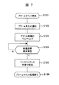
図7は、映像発信装置303のアラームイベントが発生したときの処理を示すフローチャートである。
図8は、映像記録配信装置306のアラームイベントの処理を示すフローチャートである。
図9は、映像受信装置304のアラームイベントの処理を示すフローチャートである。
図10は、映像記録配信装置306の設定モジュール403により、アラームの設定がされるときの処理を示すフローチャートである。
Hereinafter, processing relating to the alarm event and alarm setting of each device will be described with reference to FIGS.
FIG. 7 is a flowchart showing processing when an alarm event of the
FIG. 8 is a flowchart showing alarm event processing of the video recording / distributing
FIG. 9 is a flowchart showing alarm event processing of the
FIG. 10 is a flowchart showing processing when an alarm is set by the
先ず、図7を用いて映像発信装置303の処理について説明する。
First, the processing of the
映像発信装置303では、以下の図7のフローチャートに示される処理により、アラームが発生したときのトリガを受け、そのときの映像を映像記録配信装置306に配信する。
The
先ず、アラームが発生すると、そのときのトリガは、映像発信装置303に送られる。映像発信装置303は、そのトリガを受信すると、アラームイベント発生時の処理を起動する(S101)。
First, when an alarm occurs, a trigger at that time is sent to the
ここで、アラームの発生は、進入禁止エリアに人が侵入したときなど、画像処理により映像に変化がおきたときにアラームとする場合、ドアなどにセンサーを設けて、重要場所への入退者があったときにアラームとする場合などが考えうる。 Here, when an alarm is generated when a video changes due to image processing, such as when a person enters an entry-prohibited area, a sensor is installed on the door, etc., to enter or leave an important place. An alarm can be considered when there is a problem.
次に、映像発信装置303は、アラームが発生したことを、映像記録配信装置306にネットワーク回線301などを介して通知する(S102)。
Next, the
映像発信装置303は、それと同時に映像発信装置内にあるメモリなどの媒体に、映像をバッファリングする(S103)。このバッファは、映像記録配信装置306から映像の取得が来るまでに一時的に蓄えておくものである。また、このバッファに、アラームトリガが発生する前の映像からバッファリングしておいてもよい。
At the same time, the
次に、映像発信装置303は、映像記録配信装置306からそのアラーム映像取得要求を受信した場合に(S104)、バッファリングしているデータの先頭から、映像記録配信装置306に映像を配信する(S105)。
Next, when receiving the alarm video acquisition request from the video recording / distributing device 306 (S104), the
そして、映像発信装置303は、映像記録配信装置306にバッファリングしている映像データを全て配信した時点で、アラームイベント処理を終了する(S106)。
Then, the
次に、図8を用いて記録配信装置306の処理について説明する。
Next, the processing of the
映像記録配信装置306では、以下の図8に示される処理により、映像発信装置303からの映像を受信して記憶装置307に記録し、監視者が映像を閲覧する映像受信装置304へ記録した映像を配信する。
The video recording / distributing
先ず、映像記録配信装置306が起動されたときに、アラームイベントの処理を開始する(S111)。
First, when the video recording / distributing
映像記録配信装置306は、映像発信装置303からのアラームイベントを受信するまでは、アラームイベントのイベント待ちをしておく(S112)。
The video recording / distributing
そして、映像記録配信装置306が、アラーム発生の通知を受信した場合は、映像発信装置303でバッファリングしているアラーム時の映像を取得するため、映像発信装置303に対して映像取得要求をおこなう(S113)。
When the video recording / distributing
映像記録配信装置306では、映像発信装置303からの映像を受信するごとに、記憶装置307であるHDDなどに映像データを記録する(S114)。
The video recording / distributing
一方、映像記録配信装置306は、映像の記録を始めると、アラームがあったことをユーザに通知するべく、映像受信装置304にアラームが発生したことを通知する(S115)。
On the other hand, when the video recording / distributing
このアラーム発生の通知は、先の映像発信装置303からの映像取得より前におこなってもよい。また、アラームの通知を最優先にするのであれば、映像発信装置303から、映像記録配信装置306を介在することなく、直接、映像受信装置304への通知をおこなってもよい。
The notification of the alarm occurrence may be performed before the video acquisition from the previous
そして、アラーム通知をした後は、通知したアラームに対する重要度も、映像受信装置304に通知する(S116)。
After the alarm notification, the
次に、映像記録配信装置306は、映像受信装置304からの映像取得要求の受信待ちになる(S117)。
Next, the video recording / distributing
そして、映像記録配信306は、映像受信装置304から映像取得要求を受信すると、記録している映像を配信する(S118)。
Then, when receiving the video acquisition request from the
映像記録配信306は、記録した映像を配信し終えると、本アラームについての一連の処理を終了する(S119)。
When the video recording /
次に、図9を用いて映像受信装置304の処理について説明する。
Next, processing of the
映像受信装置304は、以下の図9に示される処理により、監視者の操作により指定した時刻の映像を取得し、画面に表示することで、過去の映像を閲覧する。
The
映像受信装置304は、通常、クライアントPCを使用し、ユーザインタフェースを有し、取得した映像を表示する機能を有する。通常、表示している映像は、現在のライブ映像がほとんどである。また、映像は、個人情報にもなりうることから、通常は、映像を表示しないようにしているケースもある。映像受信装置304は、クライアントPC以外にも、アナログに変換してモニタに映像を表示するデコーダという機器を使用するケースもある。
The
先ず、映像受信装置304が起動されたときに、アラームイベントの処理を開始する(S131)。
First, when the
映像受信装置304は、アラームイベントを受信するまでは、アラームイベントを受信するまで待ち続ける(S132)。
The
そして、映像記録配信装置306からのアラームイベントを受信すると、次にアラームの重要度通知を受信するまで待つ(S133)
アラームの重要度を受信すると、次に、映像記録配信装置306からそのアラーム映像を取得する(S134)。
Then, when an alarm event is received from the video recording / distributing
When the importance level of the alarm is received, the alarm video is acquired from the video recording / distributing device 306 (S134).
映像受信装置304は、アラーム発生時の映像を受信すると、そのときの画像とアラームが発生したことが分るためのマークを、表示装置305のユーザインタフェース画面に表示する(S135)。
When receiving the video at the time of the alarm occurrence, the
そのマークは、アラームを入れる文字を表示する、画面の周囲に赤枠を点滅する、パトライトを点灯する、といった形でユーザにはっきり分らせるものが好ましい。また、アラーム映像の表示は、それまで、現在のLIVE映像を表示している場合は、その映像を一時隠して、アラーム映像を表示する、また、通常映像を表示していない場合には、映像を表示するアプリケーションを自動起動して、アラーム映像を表示するといった形で、必ず、映像を閲覧してもらえるようにする。 The mark is preferably clearly displayed to the user by displaying a character for entering an alarm, blinking a red frame around the screen, or turning on a patrol light. In addition, when displaying the current LIVE video until then, the alarm video is temporarily hidden to display the alarm video, and when the normal video is not displayed, the video is displayed. Make sure that you can browse the video by automatically starting an application that displays and displaying the alarm video.
このようにして、映像を表示した場合には、アラームの重要度により映像の表示方法を変更できるようにする。 In this way, when the video is displayed, the video display method can be changed according to the importance of the alarm.
例えば、アラームの重要度が大中小と3段階ある場合(S136)、重要度小の場合は、アラーム発生時の静止画像を1枚指定した時間、例えば10秒表示する(S137)。その後は、表示装置305の表示は、現在のLIVE画像に自動的に戻るといったように通常の映像に戻る(S141)。
For example, when there are three levels of alarm importance, large, medium and small (S136), when the importance is small, a still image at the time of alarm occurrence is displayed for a specified time, for example, 10 seconds (S137). After that, the display on the
アラームの重要度が中以上の場合は、アラーム発生時前後の例えば1分の映像を自動再生する(S138)。 If the importance level of the alarm is medium or higher, for example, one minute video before and after the alarm occurrence is automatically reproduced (S138).
この場合も、例えば、表示装置305の表示は、再生が終わると現在のLIVE映像に自動的に戻るといったように通常の映像に戻る(S141)。
Also in this case, for example, the display on the
アラームの重要度が大の場合は、先ほどのアラーム映像の再生を指定回数、例えば、5回繰り返す(S139、S140)。 If the importance of the alarm is high, the previous alarm video reproduction is repeated a specified number of times, for example, five times (S139, S140).
この場合も、例えば、表示装置305の表示は、指定回数再生が終わると現在のLIVE映像に戻るといったように通常の映像に戻る(S141)。
Also in this case, for example, the display on the
上記設定が完了したら、アラームイベント処理を完了する(S142)。 When the above setting is completed, the alarm event process is completed (S142).
また例えば、指定回数分だけ再生とするのではなく、ユーザがアラーム映像の再生は必要ないと判断し終了ボタンを押すまでは、繰り返し再生して、終了ボタンを押すと現在のLIVE映像に戻るというようなユーザインタフェースでもよい。 Also, for example, instead of playing a specified number of times, the user repeatedly plays back until the user determines that the playback of the alarm video is not necessary and presses the end button, and pressing the end button returns to the current LIVE video. Such a user interface may be used.
次に、図10を用いて映像配信記録装置306のアラーム設定処理について説明する。
Next, the alarm setting process of the video
このアラーム設定処理は、図6に示した設定モジュールにより実行される。 This alarm setting process is executed by the setting module shown in FIG.
映像受信装置304の表示装置に表示されているユーザインタフェース画面から、以下の図10に示す手順により設定をおこなう。
Settings are made from the user interface screen displayed on the display device of the
先ず、アラーム映像を表示するための設定画面を表示させる(S201)。 First, a setting screen for displaying an alarm video is displayed (S201).
先ず、映像発信する映像発信装置303を、システムに登録する(S202)。
First, the
この内容には、映像発信装置303のIPアドレスや、端末名等がある。そして、この映像発信装置303の映像には、アラーム映像の録画が発信される可能性があるあるか否かを設定をする(S203)。
The contents include the IP address of the
設定される情報としては、アラーム映像のアラームの重要度の設定(S204)や、アラーム発生時に、アラーム発生イベントの通知先IPアドレスの設定(S205)などがある。上記設定が完了したら、アラーム設定処理を完了する(S206)。 The information to be set includes the setting of the alarm importance level of the alarm video (S204) and the setting of the notification destination IP address of the alarm occurrence event when the alarm occurs (S205). When the above setting is completed, the alarm setting process is completed (S206).
以上の内容は設定されると、設定モジュールにより403を介して、システム設定ファイル411、カメラ設定ファイル412に設定される。
When the above contents are set, they are set in the
次に、図11を用いて映像受信装置304に接続された表示装置305に表示されるアラーム発生時のユーザインタフェース画面を説明する。
Next, a user interface screen at the time of occurrence of an alarm displayed on the
図11は、アラーム発生時のユーザインタフェース画面を説明する図である。 FIG. 11 is a diagram illustrating a user interface screen when an alarm occurs.
例えば、施設内の不審者が入ったことを検知して、アラームイベントが発生したとする。そのときには、図11(a)に示される画面が表示されて、監視者にアラームの発生を知らせる。図11(a)の画面には、「ALARM!」というユーザに注意を促す文字が、必要なら点滅させたり、赤色などの注意を引く色によって、大きく表示される。また、このアラーム画面に、重要度と、重要度に応じて繰り返される回数が表示される。そして、現在の表示の回数も同時に表示される。この例では、施設内の不審者が入ったことを示す映像、図11(a)〜(d)が3回繰り返されることになる。 For example, it is assumed that an alarm event occurs when a suspicious person in a facility is detected. At that time, the screen shown in FIG. 11A is displayed to notify the monitor of the occurrence of the alarm. On the screen of FIG. 11A, a character “ALARM!” That calls attention to the user is displayed in a large size by blinking, if necessary, or a color that draws attention such as red. In addition, on the alarm screen, the importance level and the number of repetitions according to the importance level are displayed. The current number of displays is also displayed at the same time. In this example, a video indicating that a suspicious person in the facility has entered, and FIGS. 11A to 11D are repeated three times.
以上の方法により、アラーム映像に対して、自動的な表示とアラームに対する重要度を設けることにより、監視者は、アラーム発生時にどこで発生し、何が起こったのかを、画面を見ているだけで自動的に動作するので、作業の手間を省くことができ、効率よく監視をおこなうことができる。 By providing automatic display and alarm importance for the alarm video using the above method, the supervisor can simply look at the screen to see where the alarm occurred and what happened. Since it operates automatically, it is possible to save work and to monitor efficiently.
301…ネットワーク回線、302…映像生成装置、303…映像発信装置、304…映像受信装置、305…表示装置、306…映像記録配信装置、307…記憶装置。
DESCRIPTION OF
Claims (2)
前記映像生成装置から入力される映像を、ネットワークを介して映像記録配信装置に送信する映像発信装置と、
ネットワークを介して前記映像発信装置からの映像を受信する映像記録配信装置と、
表示装置が接続され、ネットワークを介して前記映像記録配信装置からの映像を受信して、前記表示装置に表示する映像受信装置と、を有し、
前記映像記録配信装置は、受信した映像に関するアラームイベントの重要度を、前記映像受信装置に通知し、
前記映像受信装置は、前記通知されたアラームイベントの重要度を判定し、重要度が第一の重要度であった場合にはアラームイベント時の映像を一定時間表示し、重要度が第一の重要度より高い第二の重要度であった場合にはアラームイベント時の映像を繰り返し再生して、前記表示装置に表示することを特徴とする映像配信表示システム。 A video generation device for generating video;
A video transmission device that transmits video input from the video generation device to a video recording and distribution device via a network;
A video recording / delivery device for receiving video from the video transmission device via a network;
A display device connected to the display device, receiving a video from the video recording / distributing device via a network, and displaying the video on the display device;
The video recording / distributing device notifies the video receiving device of the importance of an alarm event related to the received video,
The video receiving device determines the importance of the notified alarm event, and when the importance is the first importance, displays the video at the time of the alarm event for a certain period of time. A video distribution display system, wherein if the second importance level is higher than the importance level, the video at the time of the alarm event is repeatedly reproduced and displayed on the display device.
前記映像発信装置により映像を生成するステップと、
前記映像発信装置により前記映像を配信するステップと、
前記映像発信装置によりアラームイベントの発生を通知するステップと、
前記映像発信装置により前記アラームイベントの重要度を通知するステップと、
前記映像発信装置により通知された重要度を判定するステップと、
前記映像受信装置により受信した前記映像を前記アラームイベントの重要度が第一の重要度であった場合にはアラームイベント時の映像を一定時間表示し、重要度が第一の重要度より高い第二の重要度であった場合にはアラームイベント時の映像を繰り返し再生するステップと、
を備えることを特徴とする映像配信表示方法。 In a video distribution display system comprising a video generation device, a video transmission device, a video record distribution device, and a video reception device,
Generating a video by the video transmission device;
Delivering the video by the video transmitting device;
Notifying the occurrence of an alarm event by the video transmission device;
Notifying the importance of the alarm event by the video transmission device;
Determining the importance notified by the video transmission device;
When the importance of the alarm event is the first importance for the video received by the video receiving device, the video at the time of the alarm event is displayed for a certain time, and the importance is higher than the first importance. If it is of the second importance, the step of repeatedly playing the video at the time of the alarm event ,
A video distribution display method comprising:
Priority Applications (1)
| Application Number | Priority Date | Filing Date | Title |
|---|---|---|---|
| JP2008069427A JP5166084B2 (en) | 2008-03-18 | 2008-03-18 | Video distribution display system and video distribution display method |
Applications Claiming Priority (1)
| Application Number | Priority Date | Filing Date | Title |
|---|---|---|---|
| JP2008069427A JP5166084B2 (en) | 2008-03-18 | 2008-03-18 | Video distribution display system and video distribution display method |
Publications (3)
| Publication Number | Publication Date |
|---|---|
| JP2009225275A JP2009225275A (en) | 2009-10-01 |
| JP2009225275A5 JP2009225275A5 (en) | 2011-04-21 |
| JP5166084B2 true JP5166084B2 (en) | 2013-03-21 |
Family
ID=41241556
Family Applications (1)
| Application Number | Title | Priority Date | Filing Date |
|---|---|---|---|
| JP2008069427A Active JP5166084B2 (en) | 2008-03-18 | 2008-03-18 | Video distribution display system and video distribution display method |
Country Status (1)
| Country | Link |
|---|---|
| JP (1) | JP5166084B2 (en) |
Families Citing this family (2)
| Publication number | Priority date | Publication date | Assignee | Title |
|---|---|---|---|---|
| WO2016002203A1 (en) * | 2014-07-02 | 2016-01-07 | パナソニックIpマネジメント株式会社 | Electronic mirror device and electronic mirror device control program |
| JP2020030540A (en) * | 2018-08-21 | 2020-02-27 | アイホン株式会社 | Emergency report system |
Family Cites Families (5)
| Publication number | Priority date | Publication date | Assignee | Title |
|---|---|---|---|---|
| JP4167777B2 (en) * | 1999-07-19 | 2008-10-22 | 三菱電機株式会社 | VIDEO DISPLAY DEVICE, VIDEO DISPLAY METHOD, AND RECORDING MEDIUM CONTAINING PROGRAM FOR DISPLAYING VIDEO |
| JP2001267332A (en) * | 2000-03-17 | 2001-09-28 | Sumitomo Electric Ind Ltd | Field-effect power transistor and power device |
| JP2003223689A (en) * | 2002-01-29 | 2003-08-08 | Yokogawa Electric Corp | Monitoring system |
| JP2006041770A (en) * | 2004-07-26 | 2006-02-09 | Mitsubishi Heavy Ind Ltd | Image distribution method, image display method, wide area supervisory method employing them, image distribution apparatus and image display apparatus, and wide area supervisory system employing them |
| JP2007267332A (en) * | 2006-03-30 | 2007-10-11 | Victor Co Of Japan Ltd | Video monitoring device |
-
2008
- 2008-03-18 JP JP2008069427A patent/JP5166084B2/en active Active
Also Published As
| Publication number | Publication date |
|---|---|
| JP2009225275A (en) | 2009-10-01 |
Similar Documents
| Publication | Publication Date | Title |
|---|---|---|
| US8417090B2 (en) | System and method for management of surveillance devices and surveillance footage | |
| US20060171453A1 (en) | Video surveillance system | |
| JP2005045550A (en) | Imaging device, its imaging system and method | |
| US7451473B2 (en) | Video distribution method and video distribution system | |
| KR101562297B1 (en) | Image streaming system for minimizing use of resource for one or more Network Video Recoder | |
| JP5154341B2 (en) | Image monitoring apparatus and program | |
| JP5779380B2 (en) | Monitoring device and program | |
| JP5166084B2 (en) | Video distribution display system and video distribution display method | |
| JP2000032437A (en) | Image transmission system | |
| JP2009271612A (en) | Monitor, monitoring method, monitoring program and recording medium storing monitoring program | |
| KR20110023634A (en) | Apparatus for generating thumbnail image and method for displaying thumbnail image | |
| US8665330B2 (en) | Event-triggered security surveillance and control system, event-triggered security surveillance and control method, and non-transitory computer readable medium | |
| WO2018230104A1 (en) | Central processing device and central processing method for person-to-be-monitored monitoring assist system, and person-to-be-monitored monitoring assist system | |
| EP2541356B1 (en) | Processing monitoring data in a monitoring system | |
| JP2008085574A (en) | Network communication system | |
| JP2004326762A (en) | Image distribution system and image distribution method | |
| US9479881B2 (en) | Wireless communication apparatus, wireless communication system, and data processing method | |
| TW201441986A (en) | Emergency notification system and method | |
| JP7099687B2 (en) | Video surveillance system and its method and processing equipment | |
| JP2013101463A (en) | Monitoring device | |
| WO2004032085A1 (en) | Monitoring system and relay device | |
| WO2020100461A1 (en) | Sensor device for to-be-monitored person monitoring assistance system, monitoring image storage method, and to-be-monitored person monitoring assistance system | |
| KR200434039Y1 (en) | Centralized Surveillance System | |
| KR100400669B1 (en) | Surveillance system by using multiple cameras and method of carrying out the same | |
| JP2008294755A (en) | Video image recording apparatus |
Legal Events
| Date | Code | Title | Description |
|---|---|---|---|
| A521 | Request for written amendment filed |
Free format text: JAPANESE INTERMEDIATE CODE: A523 Effective date: 20110303 |
|
| A621 | Written request for application examination |
Free format text: JAPANESE INTERMEDIATE CODE: A621 Effective date: 20110303 |
|
| A977 | Report on retrieval |
Free format text: JAPANESE INTERMEDIATE CODE: A971007 Effective date: 20120601 |
|
| A131 | Notification of reasons for refusal |
Free format text: JAPANESE INTERMEDIATE CODE: A131 Effective date: 20120612 |
|
| A521 | Request for written amendment filed |
Free format text: JAPANESE INTERMEDIATE CODE: A523 Effective date: 20120807 |
|
| TRDD | Decision of grant or rejection written | ||
| A01 | Written decision to grant a patent or to grant a registration (utility model) |
Free format text: JAPANESE INTERMEDIATE CODE: A01 Effective date: 20121211 |
|
| A61 | First payment of annual fees (during grant procedure) |
Free format text: JAPANESE INTERMEDIATE CODE: A61 Effective date: 20121220 |
|
| FPAY | Renewal fee payment (event date is renewal date of database) |
Free format text: PAYMENT UNTIL: 20151228 Year of fee payment: 3 |
|
| R150 | Certificate of patent or registration of utility model |
Ref document number: 5166084 Country of ref document: JP Free format text: JAPANESE INTERMEDIATE CODE: R150 Free format text: JAPANESE INTERMEDIATE CODE: R150 |
|
| R250 | Receipt of annual fees |
Free format text: JAPANESE INTERMEDIATE CODE: R250 |
|
| R250 | Receipt of annual fees |
Free format text: JAPANESE INTERMEDIATE CODE: R250 |
|
| R250 | Receipt of annual fees |
Free format text: JAPANESE INTERMEDIATE CODE: R250 |
|
| R250 | Receipt of annual fees |
Free format text: JAPANESE INTERMEDIATE CODE: R250 |
|
| R250 | Receipt of annual fees |
Free format text: JAPANESE INTERMEDIATE CODE: R250 |
|
| R250 | Receipt of annual fees |
Free format text: JAPANESE INTERMEDIATE CODE: R250 |
|
| R250 | Receipt of annual fees |
Free format text: JAPANESE INTERMEDIATE CODE: R250 |
|
| R250 | Receipt of annual fees |
Free format text: JAPANESE INTERMEDIATE CODE: R250 |
|
| R250 | Receipt of annual fees |
Free format text: JAPANESE INTERMEDIATE CODE: R250 |