JP5162467B2 - Evaluation of electrode coupling for tissue ablation - Google Patents
Evaluation of electrode coupling for tissue ablation Download PDFInfo
- Publication number
- JP5162467B2 JP5162467B2 JP2008544648A JP2008544648A JP5162467B2 JP 5162467 B2 JP5162467 B2 JP 5162467B2 JP 2008544648 A JP2008544648 A JP 2008544648A JP 2008544648 A JP2008544648 A JP 2008544648A JP 5162467 B2 JP5162467 B2 JP 5162467B2
- Authority
- JP
- Japan
- Prior art keywords
- electrode
- coupling
- tissue
- phase angle
- frequency
- Prior art date
- Legal status (The legal status is an assumption and is not a legal conclusion. Google has not performed a legal analysis and makes no representation as to the accuracy of the status listed.)
- Active
Links
Images


Classifications
-
- A—HUMAN NECESSITIES
- A61—MEDICAL OR VETERINARY SCIENCE; HYGIENE
- A61B—DIAGNOSIS; SURGERY; IDENTIFICATION
- A61B18/00—Surgical instruments, devices or methods for transferring non-mechanical forms of energy to or from the body
- A61B18/04—Surgical instruments, devices or methods for transferring non-mechanical forms of energy to or from the body by heating
- A61B18/12—Surgical instruments, devices or methods for transferring non-mechanical forms of energy to or from the body by heating by passing a current through the tissue to be heated, e.g. high-frequency current
- A61B18/1206—Generators therefor
-
- A—HUMAN NECESSITIES
- A61—MEDICAL OR VETERINARY SCIENCE; HYGIENE
- A61B—DIAGNOSIS; SURGERY; IDENTIFICATION
- A61B18/00—Surgical instruments, devices or methods for transferring non-mechanical forms of energy to or from the body
- A61B18/04—Surgical instruments, devices or methods for transferring non-mechanical forms of energy to or from the body by heating
- A61B18/12—Surgical instruments, devices or methods for transferring non-mechanical forms of energy to or from the body by heating by passing a current through the tissue to be heated, e.g. high-frequency current
- A61B18/14—Probes or electrodes therefor
- A61B18/1492—Probes or electrodes therefor having a flexible, catheter-like structure, e.g. for heart ablation
-
- A—HUMAN NECESSITIES
- A61—MEDICAL OR VETERINARY SCIENCE; HYGIENE
- A61B—DIAGNOSIS; SURGERY; IDENTIFICATION
- A61B18/00—Surgical instruments, devices or methods for transferring non-mechanical forms of energy to or from the body
- A61B2018/00053—Mechanical features of the instrument of device
- A61B2018/00297—Means for providing haptic feedback
- A61B2018/00303—Means for providing haptic feedback active, e.g. with a motor creating vibrations
-
- A—HUMAN NECESSITIES
- A61—MEDICAL OR VETERINARY SCIENCE; HYGIENE
- A61B—DIAGNOSIS; SURGERY; IDENTIFICATION
- A61B18/00—Surgical instruments, devices or methods for transferring non-mechanical forms of energy to or from the body
- A61B2018/00315—Surgical instruments, devices or methods for transferring non-mechanical forms of energy to or from the body for treatment of particular body parts
- A61B2018/00345—Vascular system
- A61B2018/00351—Heart
- A61B2018/00357—Endocardium
-
- A—HUMAN NECESSITIES
- A61—MEDICAL OR VETERINARY SCIENCE; HYGIENE
- A61B—DIAGNOSIS; SURGERY; IDENTIFICATION
- A61B18/00—Surgical instruments, devices or methods for transferring non-mechanical forms of energy to or from the body
- A61B2018/00571—Surgical instruments, devices or methods for transferring non-mechanical forms of energy to or from the body for achieving a particular surgical effect
- A61B2018/00577—Ablation
-
- A—HUMAN NECESSITIES
- A61—MEDICAL OR VETERINARY SCIENCE; HYGIENE
- A61B—DIAGNOSIS; SURGERY; IDENTIFICATION
- A61B18/00—Surgical instruments, devices or methods for transferring non-mechanical forms of energy to or from the body
- A61B2018/00636—Sensing and controlling the application of energy
- A61B2018/00642—Sensing and controlling the application of energy with feedback, i.e. closed loop control
-
- A—HUMAN NECESSITIES
- A61—MEDICAL OR VETERINARY SCIENCE; HYGIENE
- A61B—DIAGNOSIS; SURGERY; IDENTIFICATION
- A61B18/00—Surgical instruments, devices or methods for transferring non-mechanical forms of energy to or from the body
- A61B2018/00636—Sensing and controlling the application of energy
- A61B2018/00666—Sensing and controlling the application of energy using a threshold value
-
- A—HUMAN NECESSITIES
- A61—MEDICAL OR VETERINARY SCIENCE; HYGIENE
- A61B—DIAGNOSIS; SURGERY; IDENTIFICATION
- A61B18/00—Surgical instruments, devices or methods for transferring non-mechanical forms of energy to or from the body
- A61B2018/00636—Sensing and controlling the application of energy
- A61B2018/00696—Controlled or regulated parameters
- A61B2018/00702—Power or energy
-
- A—HUMAN NECESSITIES
- A61—MEDICAL OR VETERINARY SCIENCE; HYGIENE
- A61B—DIAGNOSIS; SURGERY; IDENTIFICATION
- A61B18/00—Surgical instruments, devices or methods for transferring non-mechanical forms of energy to or from the body
- A61B2018/00636—Sensing and controlling the application of energy
- A61B2018/00696—Controlled or regulated parameters
- A61B2018/0075—Phase
-
- A—HUMAN NECESSITIES
- A61—MEDICAL OR VETERINARY SCIENCE; HYGIENE
- A61B—DIAGNOSIS; SURGERY; IDENTIFICATION
- A61B18/00—Surgical instruments, devices or methods for transferring non-mechanical forms of energy to or from the body
- A61B2018/00636—Sensing and controlling the application of energy
- A61B2018/00696—Controlled or regulated parameters
- A61B2018/00755—Resistance or impedance
-
- A—HUMAN NECESSITIES
- A61—MEDICAL OR VETERINARY SCIENCE; HYGIENE
- A61B—DIAGNOSIS; SURGERY; IDENTIFICATION
- A61B18/00—Surgical instruments, devices or methods for transferring non-mechanical forms of energy to or from the body
- A61B2018/00636—Sensing and controlling the application of energy
- A61B2018/00773—Sensed parameters
- A61B2018/00869—Phase
-
- A—HUMAN NECESSITIES
- A61—MEDICAL OR VETERINARY SCIENCE; HYGIENE
- A61B—DIAGNOSIS; SURGERY; IDENTIFICATION
- A61B18/00—Surgical instruments, devices or methods for transferring non-mechanical forms of energy to or from the body
- A61B2018/00636—Sensing and controlling the application of energy
- A61B2018/00773—Sensed parameters
- A61B2018/00875—Resistance or impedance
-
- A—HUMAN NECESSITIES
- A61—MEDICAL OR VETERINARY SCIENCE; HYGIENE
- A61B—DIAGNOSIS; SURGERY; IDENTIFICATION
- A61B90/00—Instruments, implements or accessories specially adapted for surgery or diagnosis and not covered by any of the groups A61B1/00 - A61B50/00, e.g. for luxation treatment or for protecting wound edges
- A61B90/06—Measuring instruments not otherwise provided for
- A61B2090/064—Measuring instruments not otherwise provided for for measuring force, pressure or mechanical tension
- A61B2090/065—Measuring instruments not otherwise provided for for measuring force, pressure or mechanical tension for measuring contact or contact pressure
-
- A—HUMAN NECESSITIES
- A61—MEDICAL OR VETERINARY SCIENCE; HYGIENE
- A61B—DIAGNOSIS; SURGERY; IDENTIFICATION
- A61B34/00—Computer-aided surgery; Manipulators or robots specially adapted for use in surgery
- A61B34/20—Surgical navigation systems; Devices for tracking or guiding surgical instruments, e.g. for frameless stereotaxis
-
- A—HUMAN NECESSITIES
- A61—MEDICAL OR VETERINARY SCIENCE; HYGIENE
- A61B—DIAGNOSIS; SURGERY; IDENTIFICATION
- A61B5/00—Measuring for diagnostic purposes; Identification of persons
- A61B5/05—Detecting, measuring or recording for diagnosis by means of electric currents or magnetic fields; Measuring using microwaves or radio waves
- A61B5/053—Measuring electrical impedance or conductance of a portion of the body
Landscapes
- Health & Medical Sciences (AREA)
- Life Sciences & Earth Sciences (AREA)
- Surgery (AREA)
- Engineering & Computer Science (AREA)
- Plasma & Fusion (AREA)
- General Health & Medical Sciences (AREA)
- Otolaryngology (AREA)
- Physics & Mathematics (AREA)
- Veterinary Medicine (AREA)
- Biomedical Technology (AREA)
- Heart & Thoracic Surgery (AREA)
- Medical Informatics (AREA)
- Molecular Biology (AREA)
- Animal Behavior & Ethology (AREA)
- Nuclear Medicine, Radiotherapy & Molecular Imaging (AREA)
- Public Health (AREA)
- Cardiology (AREA)
- Surgical Instruments (AREA)
- Measurement And Recording Of Electrical Phenomena And Electrical Characteristics Of The Living Body (AREA)
Description
(関連出願の相互参照)
本出願は、参照により本明細書に援用される、2005年12月6日に出願された米国仮特許出願第60/748,234号の利益を主張する。この出願はまた、本出願と同時に出願された国際出願整理番号0B−047801WO、同0B−047809US、同0B−047810US、同0B−047812US、同0B−047813US、同0B−047814USおよび同0B−047815US(「国際出願」)にも関連する。これら国際出願は、参照により本明細書に援用される。
(Cross-reference of related applications)
This application claims the benefit of US Provisional Patent Application No. 60 / 748,234, filed Dec. 6, 2005, which is incorporated herein by reference. This application also includes International Application Serial Nos. 0B-047801 WO, 0B-047809 US, 0B-047810 US, 0B-047812 US, 0B-047813 US, 0B-047814 US and 0B-047814 US ( Related to “International Application”). These international applications are hereby incorporated by reference.
(技術分野)
本発明は、電極カテーテルと、組織切除のために電極カテーテルを使用する方法と、に関する。特に、本発明の電極カテーテルは、標的組織に切除エネルギー(たとえばRFエネルギー)を印加するための電極・組織接触および電気的結合を評価する回路を備えてもよい。
(Technical field)
The present invention relates to electrode catheters and methods of using electrode catheters for tissue ablation. In particular, the electrode catheter of the present invention may include circuitry for evaluating electrode-tissue contact and electrical coupling for applying ablation energy (eg, RF energy) to a target tissue.
組織に損傷を形成し、その形成されている損傷の深さおよび位置を制御することができる場合、利益を得ることができるということは周知である。特に、損傷が凝固壊死を介して形成されるまで組織温度を約50℃まで上昇させる(それにより組織の電気的特性が変化する)ことが望ましい場合がある。たとえば、損傷を、凝固壊死を介して心臓組織の特定の位置に形成することにより、望ましくない心房細動を減少または除去することができる。 It is well known that if a tissue can be damaged and the depth and location of the formed damage can be controlled, benefits can be obtained. In particular, it may be desirable to increase the tissue temperature to about 50 ° C. (thus changing the electrical properties of the tissue) until damage is formed via coagulation necrosis. For example, unwanted atrial fibrillation can be reduced or eliminated by creating damage at specific locations in the heart tissue via coagulation necrosis.
しかしながら、既存の切除電極によっては、それらを使用して特定の位置に損傷を形成しようとする場合、いくつかの問題に直面する可能性がある。既存の切除電極で直面する、かかる問題の1つは、適当な組織接触および電気的結合をいかにして確実にするかである。電極・組織接触は、透視法等の従来の技法を使用することによって容易に確定されない。代りに、医師は、電極カテーテルを使用して自身の経験に基づいて電極・組織接触を確定する。かかる経験は、回数を重ねることによってのみ得られるものであり、医師が定期的に電極カテーテルを使用しない場合は急速に失われる可能性がある。さらに、心臓に損傷を形成するとき、心臓の鼓動が事態をさらに複雑にし、所望の損傷を形成するための十分な長さの時間に、電極と組織との間の十分な接触圧力を確定しかつ維持することが困難になる。電極と組織との間の接触を適当に維持することができない場合、高品質な損傷が形成されない可能性が高い。同様に、切除中に組織においてどれくらいの切除エネルギーが吸収される可能性があるかを確定するために、電極と標的組織との間の電気的結合に関する情報が事前に容易に入手できない。代りに、医師は、電極カテーテルを用いて切除処置を行う自身の経験に基づいて、出力および持続時間等、一般化された、事前に確定された切除パラメータを使用する。かかる経験は、不適当な損傷形成、早すぎる高インピーダンス遮断、組織炭化および血栓形成等、欠陥、非効率および複雑化をもたらす可能性がある。 However, some existing ablation electrodes may face several problems when they are used to create damage at a specific location. One such problem encountered with existing ablation electrodes is how to ensure proper tissue contact and electrical coupling. Electrode / tissue contact is not easily determined by using conventional techniques such as fluoroscopy. Instead, doctors use electrode catheters to establish electrode-tissue contact based on their experience. Such experience can only be gained by repeated use and can be quickly lost if the physician does not regularly use the electrode catheter. In addition, when creating damage to the heart, the heartbeat further complicates the situation and establishes sufficient contact pressure between the electrode and tissue for a sufficient length of time to form the desired damage. And difficult to maintain. If the contact between the electrode and the tissue cannot be properly maintained, it is likely that high quality damage will not be formed. Similarly, information regarding the electrical coupling between the electrode and the target tissue is not readily available in advance to determine how much ablation energy can be absorbed in the tissue during ablation. Instead, physicians use generalized, pre-established ablation parameters, such as power and duration, based on their experience performing an ablation procedure using an electrode catheter. Such experience can lead to defects, inefficiencies and complications such as inadequate damage formation, premature high impedance blockage, tissue charring and thrombus formation.
組織切除処置に使用される電極カテーテルのための電極・組織接触および電気的結合を評価することができることが望ましい。高周波(RF)切除エネルギーは、主に、約500kHzの典型的な動作周波数で抵抗加熱するが、それより低い周波数では、患者の血液および組織にキャパシタンスが存在する。血液・組織界面における抵抗およびキャパシタンスの結合された影響を測定して(たとえばインピーダンスとして)、電極と標的組織との間の種々の接触状態を自動的に評価することができる。 It would be desirable to be able to evaluate electrode-tissue contact and electrical coupling for electrode catheters used in tissue ablation procedures. Radio frequency (RF) ablation energy is primarily resistively heated at a typical operating frequency of about 500 kHz, but at lower frequencies there is capacitance in the patient's blood and tissue. The combined effects of resistance and capacitance at the blood-tissue interface can be measured (eg, as impedance) to automatically evaluate various contact conditions between the electrode and the target tissue.
例示的な電極カテーテルシステムは、電気エネルギーを印加するように構成された電極を備えてもよい。インピーダンスを測定するように構成された測定回路を、電極が標的組織に近づく際に電極と接地との間に実装してもよい。少なくとも部分的に、測定回路によって測定されるインピーダンスのリアクタンスに基づいて、標的組織に対する接触状態を確定するように、プロセッサまたは処理ユニットを実装してもよい。別の実施形態では、接触状態は、インピーダンスの位相角に基づいてもよい。 An exemplary electrode catheter system may comprise an electrode configured to apply electrical energy. A measurement circuit configured to measure impedance may be implemented between the electrode and ground as the electrode approaches the target tissue. A processor or processing unit may be implemented to determine contact conditions with the target tissue based at least in part on the reactance of the impedance measured by the measurement circuit. In another embodiment, the contact state may be based on the phase angle of the impedance.
例示的な電極カテーテルシステムは、電気エネルギーを印加するように構成された電極を備えてもよい。インピーダンスを測定するように構成された測定回路を、電極が標的組織に近づく際に電極と接地との間に実装してもよい。少なくとも部分的に、測定回路によって測定されるインピーダンスのリアクタンスに基づいて、標的組織に対する電気的結合を確定するように、プロセッサまたは処理ユニットを実装してもよい。別の実施形態では、電気的結合状態は、インピーダンスの位相角に基づいてもよい。 An exemplary electrode catheter system may comprise an electrode configured to apply electrical energy. A measurement circuit configured to measure impedance may be implemented between the electrode and ground as the electrode approaches the target tissue. A processor or processing unit may be implemented to determine electrical coupling to the target tissue based at least in part on the reactance of the impedance measured by the measurement circuit. In another embodiment, the electrical coupling state may be based on the phase angle of the impedance.
組織切除のために電極・組織接触を評価する例示的な方法は、電極が標的組織に近づく際に電極と接地との間のインピーダンスを測定することと、測定したインピーダンスからリアクタンス成分を分離することと、少なくとも部分的にリアクタンス成分に基づいて標的組織に対する接触状態を示すことと、を含んでもよい。 An exemplary method for assessing electrode-tissue contact for tissue ablation is to measure the impedance between the electrode and ground as the electrode approaches the target tissue and to separate the reactance component from the measured impedance And indicating contact with the target tissue based at least in part on the reactance component.
組織切除のために電極・組織電気的結合を評価する例示的な方法は、電極が標的組織に近づく際に電極と接地との間のインピーダンスを測定することと、測定したインピーダンスからリアクタンス成分を分離することと、少なくとも部分的にリアクタンス成分に基づいて標的組織に対する電気的結合状態を示すことと、を含んでもよい。 An exemplary method for evaluating electrode-tissue electrical coupling for tissue ablation is to measure the impedance between the electrode and ground as the electrode approaches the target tissue and to separate the reactance component from the measured impedance And indicating an electrical coupling state to the target tissue based at least in part on the reactance component.
組織切除のために電極・組織接触を評価する別の例示的な方法は、電極が標的組織に近づく際に電極と接地との間の位相角を直接測定することと、少なくとも部分的に位相角に基づいて標的組織に対する接触状態を示すことと、を含んでもよい。 Another exemplary method for assessing electrode-tissue contact for tissue ablation is to directly measure the phase angle between the electrode and ground as the electrode approaches the target tissue, and at least partially phase angle Indicating a contact state with respect to the target tissue based on.
組織切除のために電極・組織電気的結合を評価する別の例示的な方法は、電極が標的組織に近づく際に電極と接地との間の位相角を直接測定することと、少なくとも部分的に位相角に基づいて標的組織に対する電気的結合状態を指示することと、を含んでもよい。 Another exemplary method for evaluating electrode-tissue electrical coupling for tissue ablation is to directly measure the phase angle between the electrode and ground as the electrode approaches the target tissue, and at least partially Indicating an electrical coupling state to the target tissue based on the phase angle.
接触状態を、たとえば表示装置または他のインタフェースにおいて、ユーザ(たとえば医師または技師)に伝達してもよい。そして、ユーザは、接触状態をフィードバックとして使用することにより、電極カテーテルを標的組織の上に、切除処置のための所望の接触レベルで適当に位置決めすることができる。たとえば、ユーザは、接触状態が不十分な接触を示す場合、接触を増大させてもよい。またはたとえば、ユーザは、接触状態が過剰な接触を示す場合、接触を低減させてもよい。 The contact state may be communicated to a user (eg, a doctor or technician), eg, on a display device or other interface. The user can then properly position the electrode catheter over the target tissue at the desired contact level for the ablation procedure by using the contact state as feedback. For example, the user may increase contact if the contact state indicates insufficient contact. Or, for example, the user may reduce contact if the contact state indicates excessive contact.
電気的結合状態を、たとえば表示装置または他のインタフェースにおいて、ユーザ(たとえば医師または技師)に伝達してもよい。そして、ユーザは、電気的結合状態をフィードバックとして使用することにより、電極カテーテルを標的組織の上に、切除処置のための所望の結合レベルで適当に位置決めすることができる。たとえば、ユーザは、結合状態が不十分な結合を示す場合、結合を増大させてもよい。またはたとえば、ユーザは、結合状態が過剰な結合を示す場合、結合を低減させてもよい。 The electrical coupling status may be communicated to a user (eg, a doctor or technician), eg, on a display device or other interface. The user can then properly position the electrode catheter over the target tissue at the desired level of coupling for the ablation procedure by using the electrical coupling state as feedback. For example, the user may increase the bond if the bond state indicates an insufficient bond. Or, for example, a user may reduce binding if the binding state indicates excessive binding.
また、例示的な実施形態では、電流源(または別法として電圧源)を使用して、電気エネルギーを管理してもよい、ということも留意されたい。この発生源は、切除処置に使用されかつ電極の位置決め中に「ピングする(ping)」ために使用されるものと同じ発生源であってもよく、または別々に提供される発生源であってもよい。いずれの場合も定電流源(または定電圧源)を使用してもよい。別法として、組織温度に適応可能なモードで動作する切除源等、可変電流源(または可変電圧源)であってもよい。さらに、複数の電流源(または電圧源)を使用してもよい。複数の電流源(または電圧源)は、同時モード、連続モードまたは一時的にオーバラップするモードのいずれで動作可能であってもよい。 It should also be noted that in an exemplary embodiment, a current source (or alternatively a voltage source) may be used to manage electrical energy. This source may be the same source used for ablation procedures and used to “ping” during electrode positioning, or may be a source provided separately Also good. In either case, a constant current source (or constant voltage source) may be used. Alternatively, it may be a variable current source (or variable voltage source), such as an ablation source operating in a mode adaptable to tissue temperature. Further, a plurality of current sources (or voltage sources) may be used. The plurality of current sources (or voltage sources) may be operable in any of a simultaneous mode, a continuous mode, or a temporarily overlapping mode.
本発明の多数の追加の態様がある。本発明の第1態様から第7態様として特徴付けられ得るものを各々利用して、電極と組織との間の結合(以下、「電極結合」と呼ぶ場合がある)を評価してもよい。この電極結合は、電極と組織との間の機械的結合の形態、または言い換えれば、電極と組織との間に物理的接触がある状態であってもよい。別の実施形態では、この電極結合は電極と組織との間の電気的結合の形態である。電気的結合を、電極から組織に十分な量の電気エネルギーが搬送される状態と言ってもよい。また、電極結合に1つまたは複数の「程度」があってもよく、電極結合の特定の程度に関連する1つまたは複数のベンチマークは組織によって決まってもよい、ということも理解されるべきである。 There are a number of additional aspects of the invention. Each of the features that can be characterized as the first to seventh aspects of the present invention may be utilized to evaluate the bond between the electrode and the tissue (hereinafter sometimes referred to as “electrode bond”). This electrode coupling may be in the form of a mechanical coupling between the electrode and the tissue, or in other words, there is a physical contact between the electrode and the tissue. In another embodiment, the electrode coupling is in the form of an electrical coupling between the electrode and tissue. Electrical coupling may be referred to as a state where a sufficient amount of electrical energy is delivered from the electrode to the tissue. It should also be understood that there may be one or more “degrees” of electrode coupling, and one or more benchmarks associated with a particular degree of electrode coupling may be determined by the organization. is there.
本発明の第1態様は、組織に対して医療処置を行う医療システム/方法によって具現化される。第1電極を、組織に対して一定位置に配置してもよく、第1電極に第1電気信号を送出してもよい。この第1電気信号の第1電極への提供に関連する位相角を使用して、第1電極と組織との間の結合(電極結合)を評価する。より詳細には、かかる位相角を少なくとも1つの他の位相角値と比較して、電極と組織との間の結合を評価してもよい。 The first aspect of the present invention is embodied by a medical system / method for performing medical procedures on tissue. The first electrode may be placed at a fixed position with respect to the tissue, and a first electrical signal may be sent to the first electrode. The phase angle associated with providing this first electrical signal to the first electrode is used to evaluate the coupling between the first electrode and the tissue (electrode coupling). More particularly, such a phase angle may be compared with at least one other phase angle value to assess the coupling between the electrode and the tissue.
本発明の第1態様に関連して言及する特徴のさまざまな改良がある。本発明の第1態様にさらなる特徴を同様に組み込んでもよい。これら改良およびさらなる特徴は、個々に存在してもよく、または任意の組合せで存在してもよい。最初に、第5態様に関連して後述する特徴を、この第1態様に組み込んでもよい。 There are various improvements to the features mentioned in connection with the first aspect of the invention. Additional features may be similarly incorporated into the first aspect of the invention. These refinements and additional features may exist individually or in any combination. Initially, features described below in connection with the fifth aspect may be incorporated into this first aspect.
第1態様による位相角比較のために、少なくとも1つの位相角ベンチマーク値を提供してもよい。一実施形態では、この位相角ベンチマーク値は、データ構造内に格納されるか、または位相角比較器等によってアクセス可能である。一実施形態では、位相角ベンチマーク値は、不十分な結合状態に関連する。別の実施形態では、位相角ベンチマーク値は、高(elevated)結合状態または過度な結合状態に関連する。 At least one phase angle benchmark value may be provided for phase angle comparison according to the first aspect. In one embodiment, this phase angle benchmark value is stored in a data structure or accessible by a phase angle comparator or the like. In one embodiment, the phase angle benchmark value is associated with insufficient coupling. In another embodiment, the phase angle benchmark value is associated with an elevated or excessive coupling state.
第1態様の一実施形態では、電極結合を評価するために、位相角比較に対し1つまたは複数のカテゴリまたは範囲を提供してもよい。任意の適当な数の位相角カテゴリまたは範囲を使用してもよく、これら位相角カテゴリまたは範囲を、任意の適当な方法で(たとえば実験的に)確定しまたは設定してもよい。たとえば、1)第1範囲は、不十分な結合状態に関連する位相角を含んでもよく、それらを位相角比較器等が、第1電気信号に関連する位相角がこの第1範囲内にあるか否かを確定するために利用してもよく、2)第2範囲は、十分な結合状態に関連する位相角を含んでもよく、それらを位相角比較器等が、第1電気信号に関連する位相角がこの第2範囲内にあるか否かを確定するために利用してもよく、3)第3範囲は、高結合状態または過度な結合状態に関連する位相角を含んでもよく、それらを位相角比較器等が、第1電気信号に関連する位相角がこの第3範囲内にあるか否かを確定するために利用してもよい。これら第1範囲、第2範囲および第3範囲の各々を、第1電気信号に関連する位相角と比較するために個々に使用することができ、または、互いに適当に結合して使用してもよい。何が「不十分である」、「十分である」「高い/過度である」かは、1つまたは複数の他の要因とともに、第1電極に結合されている組織によって決まり得る、ということが理解されるべきである。 In one embodiment of the first aspect, one or more categories or ranges may be provided for the phase angle comparison to assess electrode coupling. Any suitable number of phase angle categories or ranges may be used, and these phase angle categories or ranges may be established or set in any suitable manner (eg, experimentally). For example, 1) the first range may include phase angles associated with poor coupling conditions, such as a phase angle comparator or the like, wherein the phase angle associated with the first electrical signal is within this first range. 2) The second range may include a phase angle associated with a sufficient coupling state, which may be used by a phase angle comparator or the like to relate to the first electrical signal. May be utilized to determine whether the phase angle to be within this second range or not 3) The third range may include a phase angle associated with a high or excessive coupling state, They may be used by a phase angle comparator or the like to determine whether the phase angle associated with the first electrical signal is within this third range. Each of these first, second, and third ranges can be used individually to compare with the phase angle associated with the first electrical signal, or can be used in conjunction with each other as appropriate. Good. What is “insufficient”, “sufficient”, “high / excessive” can depend on the tissue coupled to the first electrode, along with one or more other factors. Should be understood.
医療処置の一定時点での第1電気信号に関連する位相角を、第1態様によりこの一定時点で、任意の適当な方法で、かつ電極結合を評価する目的で確定してもよい。当然ながら、電極結合を、何らかの所定の時間に基づいて、または何らかの事前定義された関数に従って評価することが望ましい場合もある(たとえば、医療処置の少なくとも一部の間に「x」秒毎に第1電気信号に関連する位相角を評価する)。一実施形態では、第1電気信号に関連する位相角は、第1電極に提供されている電流と、第1電極と戻り電極等の別の電極との間に存在する電圧と、の間の位相角である。 The phase angle associated with the first electrical signal at a certain point in time for the medical procedure may be determined at any certain point in time according to the first aspect and for the purpose of assessing electrode coupling. Of course, it may be desirable to evaluate electrode coupling based on some predetermined time or according to some predefined function (eg, every second “x” seconds during at least part of a medical procedure). (Evaluate the phase angle associated with one electrical signal). In one embodiment, the phase angle associated with the first electrical signal is between a current provided to the first electrode and a voltage present between the first electrode and another electrode, such as a return electrode. The phase angle.
本発明の第2態様は、組織に対し医療処置を行う医療システム/方法によって具現化される。第1電極を、組織に対して一定位置に配置してもよく、第1電極に第1電気信号を送出してもよい。この第1電気信号の第1電極への提供に関連するリアクタンスを使用して、第1電極と組織との間の結合(電極結合)を評価する。より詳細には、かかるリアクタンスを少なくとも1つの他のリアクタンス値と比較して、電極と組織との間の結合を評価してもよい。 The second aspect of the present invention is embodied by a medical system / method for performing medical procedures on tissue. The first electrode may be placed at a fixed position with respect to the tissue, and a first electrical signal may be sent to the first electrode. The reactance associated with providing the first electrical signal to the first electrode is used to evaluate the coupling between the first electrode and the tissue (electrode coupling). More particularly, such reactance may be compared to at least one other reactance value to assess the coupling between the electrode and tissue.
本発明の第2態様に関連して言及する特徴のさまざまな改良がある。本発明の第2態様にさらなる特徴を同様に組み込んでもよい。これら改良およびさらなる特徴は、個々に存在してもよく、または任意の組合せで存在してもよい。最初に、第5態様に関連して後述する特徴を、この第2態様に組み込んでもよい。 There are various improvements to the features mentioned in connection with the second aspect of the invention. Additional features may be similarly incorporated into the second aspect of the invention. These refinements and additional features may exist individually or in any combination. Initially, features described below in connection with the fifth aspect may be incorporated into this second aspect.
第2態様によるリアクタンス比較のために、少なくともリアクタンスベンチマーク値を提供してもよい。一実施形態では、このリアクタンスベンチマーク値は、データ構造内に格納されるか、またはリアクタンス比較器等によってアクセス可能である。一実施形態では、リアクタンスベンチマーク値は、不十分な結合状態に関連する。別の実施形態では、リアクタンスベンチマーク値は、高結合状態または過度な結合状態に関連する。 At least a reactance benchmark value may be provided for reactance comparison according to the second aspect. In one embodiment, this reactance benchmark value is stored in a data structure or accessible by a reactance comparator or the like. In one embodiment, the reactance benchmark value is associated with insufficient binding. In another embodiment, the reactance benchmark value is associated with a high or excessive binding state.
第2態様の一実施形態では、電極結合を評価するリアクタンス比較に対し、1つまたは複数のカテゴリまたは範囲を提供してもよい。任意の適当な数のリアクタンスカテゴリまたは範囲を使用してもよく、これらリアクタンスカテゴリまたは範囲を、任意の適当な方法で(たとえば実験的に)確定しまたは設定してもよい。たとえば、1)第1範囲は、不十分な結合状態に関連するリアクタンス値を含んでもよく、それらをリアクタンス比較器等が、第1電気信号に関連するリアクタンスがこの第1範囲内にあるか否かを確定するために利用してもよく、2)第2範囲は、十分な結合状態に関連するリアクタンス値を含んでもよく、それらをリアクタンス比較器等が、第1電気信号に関連するリアクタンスがこの第2範囲内にあるか否かを確定するために利用してもよく、3)第3範囲は高結合状態または過度な結合状態に関連するリアクタンス値を含んでもよく、それらをリアクタンス比較器等が、第1電気信号に関連するリアクタンスがこの第3範囲内にあるか否かを確定するために利用してもよい。これら第1範囲、第2範囲および第3範囲の各々を、第1電気信号に関連するリアクタンスと比較するために個々に使用することができ、または、互いに適当に結合して使用してもよい。何が「不十分である」、「十分である」「高い/過度である」かは、1つまたは複数の他の要因とともに、第1電極に結合されている組織によって決まり得る、ということが理解されるべきである。 In one embodiment of the second aspect, one or more categories or ranges may be provided for reactance comparisons that evaluate electrode coupling. Any suitable number of reactance categories or ranges may be used, and these reactance categories or ranges may be established or set in any suitable manner (eg, experimentally). For example, 1) the first range may include reactance values associated with poor coupling conditions, such as reactance comparators, etc., whether the reactance associated with the first electrical signal is within this first range. 2) The second range may include reactance values associated with sufficient coupling conditions, such as reactance comparators, etc., for reactance associated with the first electrical signal. It may be used to determine whether it is within this second range, or 3) the third range may contain reactance values associated with a high coupling state or an excessive coupling state, which are used as reactance comparators. May be used to determine whether the reactance associated with the first electrical signal is within this third range. Each of these first range, second range, and third range can be used individually to compare with reactance associated with the first electrical signal, or can be used in appropriate combination with each other. . What is “insufficient”, “sufficient”, “high / excessive” can depend on the tissue coupled to the first electrode, along with one or more other factors. Should be understood.
医療処置の一定時点での第1電気信号に関連するリアクタンスを、第2態様によりこの一定時点で、任意の適当な方法で、かつ電極結合を評価する目的で確定してもよい。当然ながら、電極結合を、何らかの所定の時間に基づいて、または何らかの事前定義された関数に従って評価することが望ましい場合もある(たとえば、医療処置の少なくとも一部の間に「x」秒毎に第1電気信号に関連するリアクタンスを評価する)。一実施形態では、第1電気信号に関連するリアクタンスは、第1電極と戻り電極等の別の電極との間の電気経路に関連するリアクタンスである。 The reactance associated with the first electrical signal at a certain point in time in the medical procedure may be determined at any given time and for the purpose of assessing electrode coupling according to the second aspect. Of course, it may be desirable to evaluate electrode coupling based on some predetermined time or according to some predefined function (eg, every second “x” seconds during at least part of a medical procedure). Evaluate reactance associated with one electrical signal). In one embodiment, the reactance associated with the first electrical signal is the reactance associated with the electrical path between the first electrode and another electrode, such as the return electrode.
本発明の第3態様は、組織に対して医療処置を行う医療システム/方法によって具現化される。第1電極を、組織に対して一定位置に配置してもよく、第1電極に第1電気信号を送出してもよい。この第1電気信号の第1電極への提供に関連するインピーダンス成分比として特徴付けることができるものを使用して、第1電極と組織との間の結合(電極結合)を評価する。この「インピーダンス成分比」は、第1電気信号の提供に関連するインピーダンスを画定する2つの成分値(たとえば、抵抗、リアクタンス、インピーダンス)の比である。より詳細には、かかるインピーダンス成分比を少なくとも1つの他のインピーダンス成分比値と比較して、電極と組織との間の結合を評価してもよい。 The third aspect of the present invention is embodied by a medical system / method for performing medical procedures on tissue. The first electrode may be placed at a fixed position with respect to the tissue, and a first electrical signal may be sent to the first electrode. Using what can be characterized as the impedance component ratio associated with the provision of this first electrical signal to the first electrode, the coupling between the first electrode and the tissue (electrode coupling) is evaluated. This “impedance component ratio” is the ratio of two component values (eg, resistance, reactance, impedance) that define the impedance associated with providing the first electrical signal. More particularly, such impedance component ratio may be compared with at least one other impedance component ratio value to assess the coupling between the electrode and the tissue.
本発明の第4態様は、組織に対して医療処置を行う医療システム/方法によって具現化される。第1電極を、組織に対して一定位置に配置してもよく、第1電極に第1電気信号を送出してもよい。高結合状態または過度な結合状態(たとえば、機械的、電気的または両方)の展開を、適当な評価を通して識別することができる。 The fourth aspect of the present invention is embodied by a medical system / method for performing medical procedures on tissue. The first electrode may be placed at a fixed position with respect to the tissue, and a first electrical signal may be sent to the first electrode. Developments in high or excessive coupling (eg, mechanical, electrical, or both) can be identified through appropriate evaluation.
本発明の第4態様に関連して言及する特徴のさまざまな改良がある。本発明の第4態様にさらなる特徴を同様に組み込んでもよい。これら改良およびさらなる特徴は、個々に存在してもよく、または任意の組合せで存在してもよい。最初に、第5態様に関連して後述する特徴を、この第4態様に組み込んでもよい。 There are various improvements to the features mentioned in connection with the fourth aspect of the invention. Additional features may be similarly incorporated into the fourth aspect of the invention. These refinements and additional features may exist individually or in any combination. Initially, features described below in connection with the fifth aspect may be incorporated into this fourth aspect.
第4態様の場合に第1電極と組織との間の高結合状態または過度な結合状態の存在を識別する目的で、限定なしにインピーダンス、位相角(たとえば第1態様による)、リアクタンス(たとえば第2態様による)および標的周波数(たとえば、後述する第7態様による)を含む、1つまたは複数のパラメータを監視し/評価してもよい。(たとえば、第1電極から患者の身体を通って戻り電極まで延在する電気回路の一部の)リアクタンスを、少なくとも1つのリアクタンスベンチマーク値と比較することにより、過度な結合状態が存在するか否かを確定してもよい。一実施形態では、高結合状態または過度な結合状態は、リアクタンスが所定の負のリアクタンス値を下回る状態に相当するものとする。位相角(たとえば、第1電極における電流と、第1電極と戻り電極との間の電圧と、の間の位相角)を少なくとも1つの位相角ベンチマーク値と比較することにより、高結合状態または過度な結合状態が存在するか否かを確定してもよい。一実施形態では、高結合状態または過度な結合状態は、位相角が所定の負の位相角値を下回る状態に相当するものとする。 For the purpose of identifying the presence of a high or excessive coupling state between the first electrode and tissue in the case of the fourth embodiment, without limitation, impedance, phase angle (for example according to the first embodiment), reactance (for example first One or more parameters may be monitored / evaluated, including according to two aspects) and a target frequency (eg according to the seventh aspect described below). Whether there is excessive coupling by comparing the reactance (eg, part of the electrical circuit extending from the first electrode through the patient's body to the return electrode) with at least one reactance benchmark value It may be determined. In one embodiment, a high or excessive coupling state shall correspond to a state where the reactance is below a predetermined negative reactance value. By comparing the phase angle (eg, the phase angle between the current in the first electrode and the voltage between the first electrode and the return electrode) with at least one phase angle benchmark value, It may be determined whether or not there is a combined state. In one embodiment, a high or excessive coupling state shall correspond to a state where the phase angle is below a predetermined negative phase angle value.
位相角が一定の事前設定値(たとえば、第1電極における電流と、第1電極と戻り電極との間の電圧と、の間の位相角)である、第1電気信号に対する周波数を、「標的周波数」と呼んでもよく、この第4態様の目的のために、この標的周波数を少なくとも1つの周波数ベンチマーク値と比較することにより、高結合状態または過度な結合状態が存在するか否かを確定してもよい。一実施形態では、高結合状態または過度な結合状態は、所定周波数値を上回る標的周波数を有することに相当するものとする。(たとえば、第1の電極から患者の身体を通って戻り電極まで延在する電気回路の一部の)インダクタンスが一定の事前設定値である、第1電気信号に対する周波数が、同様に標的周波数を画定してもよく、この標的周波数を少なくとも1つの周波数ベンチマーク値と比較することにより、高結合状態または過度な結合状態が存在するか否かを確定してもよい。一実施形態では、高結合状態または過度な結合状態は、所定周波数値を上回る標的周波数を有することに相当するものとする。概して、適当な電気パラメータは、標的周波数に関連する可能性があり、標的周波数の目的のためにこの電気パラメータに対して任意の適当な値を使用してもよい。標的周波数を上回る周波数が、ある状態に関連する可能性があり、標的周波数を下回る周波数が、ある状態に関連する可能性があり、または両方である。 The frequency for the first electrical signal, which is a preset value with a constant phase angle (eg, the phase angle between the current at the first electrode and the voltage between the first electrode and the return electrode) is expressed as “target For the purposes of this fourth aspect, the target frequency is compared with at least one frequency benchmark value to determine if there is a high or excessive coupling state. May be. In one embodiment, a high or excessive coupling state shall correspond to having a target frequency above a predetermined frequency value. The frequency for the first electrical signal, where the inductance is a constant preset value (eg, the portion of the electrical circuit extending from the first electrode through the patient's body to the return electrode) is also the target frequency. It may be defined and by comparing this target frequency with at least one frequency benchmark value, it may be determined whether a high coupling state or an excessive coupling state exists. In one embodiment, a high or excessive coupling state shall correspond to having a target frequency above a predetermined frequency value. In general, a suitable electrical parameter can be related to the target frequency, and any suitable value for this electrical parameter may be used for the purpose of the target frequency. A frequency above the target frequency may be associated with a condition, and a frequency below the target frequency may be associated with a condition, or both.
本発明の第5態様は、組織に対して医療処置を行う医療システム/方法によって具現化される。第1電極を、組織に対して一定位置に配置してもよく、第1電極に、第1電流を提供する第1電気信号を送出してもよい。この第1電流を使用して、第1医療処置(たとえば心臓組織の切除)が行われる。この第1電流を使用して、第1電極と組織との間の結合も評価される。 The fifth aspect of the present invention is embodied by a medical system / method for performing medical procedures on tissue. The first electrode may be placed at a fixed position relative to the tissue, and a first electrical signal providing a first current may be delivered to the first electrode. This first current is used to perform a first medical procedure (eg, ablation of heart tissue). Using this first current, the coupling between the first electrode and the tissue is also evaluated.
本発明の第5態様に関連して言及する特徴のさまざまな改良がある。本発明の第5態様にさらなる特徴を同様に組み込んでもよい。これら改良およびさらなる特徴は、個々に存在してもよく、または任意の組合せで存在してもよい。第5態様の場合の第1電極と組織との間の結合を、任意の適当なパラメータで評価してもよい。この評価は、インピーダンス比較、位相角比較(たとえば第1態様による)、リアクタンス比較(たとえば第2態様による)および標的周波数比較(たとえば後述する第7態様による)に基づいてもよい。 There are various improvements to the features mentioned in connection with the fifth aspect of the invention. Additional features may be similarly incorporated into the fifth aspect of the invention. These refinements and additional features may exist individually or in any combination. The coupling between the first electrode and the tissue in the case of the fifth aspect may be evaluated with any appropriate parameter. This evaluation may be based on impedance comparison, phase angle comparison (eg, according to the first aspect), reactance comparison (eg, according to the second aspect) and target frequency comparison (eg, according to the seventh aspect described later).
第5態様の場合、第1電極に、第2電流を提供する第2電気信号を送出してもよい。第1電極と組織との間の結合を、この第2信号を使用して評価してもよい。第2電気信号に関連してさまざまな特徴付けを行ってもよく、それは個々に、または任意の組合せで適用される。1)第2電流は第1電流を下回る場合があり、2)第1電気信号および第2電気信号は、少なくとも概して同じ周波数である可能性があり、3)第1信号および第2信号は、逐次、または同時以外の方法で、たとえば1つの電源から別の電源に切り替えることにより送出される可能性がある。後者に関して、第1電極を第1電源(たとえば評価電源)と相互接続するように1つの位置にスイッチを配置してもよく、第1電極結合評価モジュールを使用して電極結合を評価してもよい。このスイッチを別の位置に配置することにより、第1電極を第2電源(たとえば切除電源)と相互接続してもよく、第2電極結合評価モジュールを使用して電極結合を評価してもよい。これら第1電極結合評価モジュールおよび第2電極結合評価モジュールは、共通の構成であってもよい。 In the case of the fifth aspect, a second electrical signal that provides a second current may be sent to the first electrode. The coupling between the first electrode and the tissue may be assessed using this second signal. Various characterizations may be made in connection with the second electrical signal, which are applied individually or in any combination. 1) The second current may be less than the first current, 2) the first electrical signal and the second electrical signal may be at least generally the same frequency, and 3) the first signal and the second signal are It may be sent in a manner other than sequential or simultaneous, for example by switching from one power source to another. With respect to the latter, a switch may be placed in one position to interconnect the first electrode with a first power source (eg, an evaluation power source), and the electrode coupling may be evaluated using the first electrode coupling evaluation module. Good. By placing this switch in a different position, the first electrode may be interconnected with a second power source (eg, ablation power source) and the electrode coupling may be evaluated using a second electrode coupling evaluation module. . The first electrode coupling evaluation module and the second electrode coupling evaluation module may have a common configuration.
本発明の第6態様は、組織に対して医療処置を行う医療システム/方法によって具現化される。一実施形態では、第1電極を有する第1カテーテルが、患者の心臓の第1腔(たとえば左心房)内に、第2電極を有する第2カテーテルとともに配置される。別の実施形態では、第1電極先端および第2電極先端(たとえば、異なるカテーテルに関連する、共通のカテーテルに関連する)が、心臓の第1腔内に配置される。各場合において、第1医療処置を行うために第1電気信号を第1電極に送出してもよく、第1電極と組織との間の結合を、この第1電気信号を使用して評価してもよい。 The sixth aspect of the present invention is embodied by a medical system / method for performing medical procedures on tissue. In one embodiment, a first catheter having a first electrode is placed in a first chamber (eg, the left atrium) of a patient's heart with a second catheter having a second electrode. In another embodiment, a first electrode tip and a second electrode tip (eg, associated with a common catheter, associated with different catheters) are disposed within the first chamber of the heart. In each case, a first electrical signal may be delivered to the first electrode to perform a first medical procedure, and the coupling between the first electrode and the tissue is evaluated using this first electrical signal. May be.
本発明の第6態様に関連して言及する特徴のさまざまな改良がある。本発明の第6態様にさらなる特徴を同様に組み込んでもよい。これら改良およびさらなる特徴は、個々に存在してもよく、または任意の組合せで存在してもよい。第6態様の場合の第1電極と組織との間の結合を、任意の適当なパラメータで評価してもよい。この評価は、インピーダンス比較、位相角比較(たとえば第1態様による)、リアクタンス比較(たとえば第2態様による)および標的周波数比較(たとえば後述する第7態様による)に基づいてもよい。さらに、第5態様に関連して上述した特徴をこの第6態様に組み込んでもよい。 There are various improvements to the features mentioned in connection with the sixth aspect of the invention. Additional features may be similarly incorporated into the sixth aspect of the invention. These refinements and additional features may exist individually or in any combination. The connection between the first electrode and the tissue in the case of the sixth embodiment may be evaluated with any appropriate parameter. This evaluation may be based on impedance comparison, phase angle comparison (eg, according to the first aspect), reactance comparison (eg, according to the second aspect) and target frequency comparison (eg, according to the seventh aspect described later). Furthermore, the features described above in connection with the fifth aspect may be incorporated into this sixth aspect.
本発明の第7態様は、組織に対して医療処置を行う医療システム/方法によって具現化される。第1電極を、組織に対して一定位置に配置してもよく、第1電極に第1電気信号を送出してもよい。1つまたは複数の周波数を分析することにより、電気パラメータが一定値(ここで「値」は値の一定範囲を含む)である周波数を識別することができる。 The seventh aspect of the present invention is embodied by a medical system / method for performing medical procedures on tissue. The first electrode may be placed at a fixed position with respect to the tissue, and a first electrical signal may be sent to the first electrode. By analyzing one or more frequencies, the frequency at which the electrical parameter is a constant value (where “value” includes a certain range of values) can be identified.
本発明の第7態様に関連して言及する特徴のさまざまな改良がある。本発明の第7態様にさらなる特徴を同様に組み込んでもよい。これら改良およびさらなる特徴は、個々に存在してもよく、または任意の組合せで存在してもよい。標的周波数は、周波数がゼロ位相角(たとえば、第1電極に提供されている電流と、第1電極と戻り電極等の別の電極との間に存在する電圧と、の間の位相角)を提供する場合であってもよい。ゼロ周波数はまた、周波数がゼロのインダクタンス(たとえば、第1電極から患者の身体を通って戻り電極まで延在する電気回路の一部のインダクタンス)を提供する場合であってもよい。標的周波数の目的で任意の電気パラメータを使用してもよく、この電気パラメータは、標的周波数の目的で任意の適当な値であってもよい。一実施形態では、標的周波数は、複数の電気信号を異なる周波数で逐次提供し(たとえば、周波数掃引を使用する)、これら電気信号のいずれが必要な値の電気パラメータを生成するかを確定することによって識別される。別の実施形態では、複数の周波数を含む電気信号が第1電極に送出される。フィルタを使用して、この共通の電気信号からのさまざまな周波数の各々が別々に分析されることにより、これら周波数のいずれかが必要な値の電気パラメータを生成するか否かを確定することを可能にしてもよい。 There are various improvements to the features mentioned in connection with the seventh aspect of the invention. Additional features may be similarly incorporated into the seventh aspect of the invention. These refinements and additional features may exist individually or in any combination. The target frequency is the frequency at which the phase angle is zero (eg, the phase angle between the current being provided to the first electrode and the voltage present between the first electrode and another electrode such as the return electrode). It may be provided. The zero frequency may also be when providing a zero frequency inductance (eg, the inductance of the portion of the electrical circuit that extends from the first electrode through the patient's body to the return electrode). Any electrical parameter may be used for the purpose of the target frequency, and this electrical parameter may be any suitable value for the purpose of the target frequency. In one embodiment, the target frequency provides multiple electrical signals sequentially at different frequencies (eg, using a frequency sweep) and determines which of these electrical signals produces the required value of electrical parameters. Identified by. In another embodiment, an electrical signal comprising multiple frequencies is delivered to the first electrode. Using a filter, each of the various frequencies from this common electrical signal is analyzed separately to determine whether any of these frequencies produces the required value of the electrical parameter. It may be possible.
標的周波数を使用して、第7態様の場合に第1電極と組織との間の結合を評価してもよい。これに関して、電極結合を評価する第7態様による周波数比較のために少なくとも1つの周波数ベンチマーク値を提供してもよい。一実施形態では、この周波数ベンチマーク値は、データ構造内に格納されるか、または周波数比較器等によってアクセス可能である。一実施形態では、周波数ベンチマーク値は、不十分な結合状態に関連する。別の実施形態では、周波数ベンチマーク値は、高結合状態または過度な結合状態に関連する。 The target frequency may be used to evaluate the coupling between the first electrode and the tissue in the case of the seventh aspect. In this regard, at least one frequency benchmark value may be provided for frequency comparison according to the seventh aspect of assessing electrode coupling. In one embodiment, this frequency benchmark value is stored in a data structure or accessible by a frequency comparator or the like. In one embodiment, the frequency benchmark value is associated with insufficient coupling. In another embodiment, the frequency benchmark value is associated with a high or excessive coupling state.
第7態様の一実施形態では、電極結合を評価するために、周波数比較に対し1つまたは複数のカテゴリまたは範囲を提供してもよい。任意の適当な数の周波数カテゴリまたは範囲を使用してもよく、これら周波数カテゴリまたは範囲を、任意の適当な方法で(たとえば実験的に)確定しまたは設定してもよい。たとえば、1)第1範囲は、不十分な結合状態に関連する周波数を含んでもよく、それらを周波数比較器等が、標的周波数がこの第1範囲内にあるか否かを確定するために利用してもよく、2)第2範囲は、十分な結合状態に関連する周波数を含んでもよく、それらを周波数比較器等が、標的周波数がこの第2範囲内にあるか否かを確定するために利用してもよく、3)第3範囲は高結合状態または過度な結合状態に関連する周波数を含んでもよく、それらを周波数比較器等が、標的周波数がこの第3範囲内にあるか否かを確定するために利用してもよい。これら第1範囲、第2範囲および第3範囲の各々を、標的周波数と比較するために個々に使用することができ、または、互いに適当に結合して使用してもよい。何が「不十分である」、「十分である」「高い/過度である」かは、1つまたは複数の他の要因とともに、第1電極に結合されている組織によって決まり得る、ということが理解されるべきである。 In one embodiment of the seventh aspect, one or more categories or ranges may be provided for frequency comparison to assess electrode coupling. Any suitable number of frequency categories or ranges may be used, and these frequency categories or ranges may be established or set in any suitable manner (eg, experimentally). For example, 1) the first range may include frequencies associated with insufficient coupling conditions, which are used by a frequency comparator or the like to determine whether the target frequency is within this first range. 2) The second range may include frequencies associated with sufficient coupling conditions, so that a frequency comparator or the like determines whether the target frequency is within this second range. 3) The third range may include frequencies associated with a high coupling state or an excessive coupling state, and these are used by a frequency comparator or the like to determine whether the target frequency is within this third range. It may be used to determine whether or not. Each of these first range, second range, and third range can be used individually to compare to the target frequency, or can be used in conjunction with each other as appropriate. What is “insufficient”, “sufficient”, “high / excessive” can depend on the tissue coupled to the first electrode, along with one or more other factors. Should be understood.
第1態様から第7態様までの各々に適用可能な多数の特徴等があり、それについてここで要約する。第1電極は、任意の適当なサイズ、形状、構成および/またはタイプであってもよく、さらに、第1電極を使用して、任意のタイプの医療処置(たとえば切除)を行ってもよい。一実施形態では、第1電極はカテーテル電極の形態である。 There are a number of features that can be applied to each of the first to seventh aspects, which are summarized here. The first electrode may be any suitable size, shape, configuration and / or type, and the first electrode may be used to perform any type of medical procedure (eg, ablation). In one embodiment, the first electrode is in the form of a catheter electrode.
第1態様から第7態様までの場合、第1電気信号は任意の適当な周波数であってもよい。一実施形態では、かつ第7態様の場合を除き、電極結合評価を提供する目的では、単一周波数があればよい。任意の適当な電源または信号発生器を使用して、第1電気信号または他の任意の電気信号を提供してもよい。かかる電源または信号発生器の各々を、第1電極に連続的に相互接続してもよく、またはスイッチ等の動作を通して要求/必要に応じて電気的に相互接続してもよい。 In the case of the first aspect to the seventh aspect, the first electric signal may have any suitable frequency. In one embodiment, and except for the case of the seventh aspect, for the purpose of providing an electrode coupling evaluation, there may be a single frequency. Any suitable power source or signal generator may be used to provide the first electrical signal or any other electrical signal. Each such power supply or signal generator may be continuously interconnected to the first electrode or may be electrically interconnected as required / needed through operation of a switch or the like.
第1態様から第7態様の場合に、第1電極と組み合せて戻り電極を使用することにより、第1電極を使用して医療処置を行ってもよく、それはまた、電極結合評価に使用してもよい。かかる戻り電極に関連する以下の特徴を、個々に使用してもよく、または任意の適当な組合せで使用してもよい。1)第1電極および戻り電極の各々は、カテーテル電極の形態であってもよく、かかるカテーテル電極の各々は独立して移動可能であってもよく、2)戻り電極は、第1電極より広い表面積を利用してもよく、3)第1電極および戻り電極の各々は、左心房等の心臓の共通腔内に配置可能であってもよい。 In the case of the first aspect to the seventh aspect, a medical procedure may be performed using the first electrode by using the return electrode in combination with the first electrode, which is also used for the electrode coupling evaluation. Also good. The following features associated with such return electrodes may be used individually or in any appropriate combination. 1) Each of the first electrode and the return electrode may be in the form of a catheter electrode, and each such catheter electrode may be independently movable 2) The return electrode is wider than the first electrode Surface area may be utilized. 3) Each of the first electrode and the return electrode may be positionable within a common chamber of the heart, such as the left atrium.
第1態様から第7態様によって使用されるいかなる電極結合評価も、少なくとも1つの電極結合評価モジュール(たとえば電気回路)を利用してもよい。かかる電極結合評価モジュールの各々を、任意の適当な方法でかつ任意の適当な位置に組み込んでもよい。たとえば、電極結合評価モジュールをカテーテルに組み込んでもよく、独立形ユニットの形態にしてもよく、電力発生器によって組み込んでもよく、電気生理学マッピングシステムによって組み込んでもよく、または電気生理学信号記録システムによって組み込んでもよい。 Any electrode coupling evaluation used by the first to seventh aspects may utilize at least one electrode coupling evaluation module (eg, an electrical circuit). Each such electrode coupling evaluation module may be incorporated in any suitable manner and in any suitable location. For example, the electrode coupling evaluation module may be incorporated into the catheter, may be in the form of a stand-alone unit, may be incorporated by a power generator, may be incorporated by an electrophysiology mapping system, or may be incorporated by an electrophysiology signal recording system. .
第1態様から第7態様の各々を使用して、高結合状態または過度な結合状態の存在を識別してもよい。かかる高結合状態または過度な結合状態の存在を識別する能力は、多数の理由で望ましい場合がある。たとえば、高結合状態または過度な結合状態を回避することが望ましい場合がある(たとえば、組織壁または膜を穿孔する可能性を低減するため)。また、高結合状態または過度な結合状態に達することが望ましい場合もある(たとえば、組織壁または膜に第1電極を通す可能性を増大させるため)。 Each of the first through seventh aspects may be used to identify the presence of a high or excessive binding state. The ability to identify the presence of such high or excessive binding states may be desirable for a number of reasons. For example, it may be desirable to avoid high or excessive bonding (eg, to reduce the possibility of perforating tissue walls or membranes). It may also be desirable to reach a highly or excessively bonded state (eg, to increase the likelihood of passing the first electrode through a tissue wall or membrane).
第1態様から第7態様によって使用されるいずれの位相角比較も、位相角の測定/確定を容易にするために移相回路を利用してもよい。たとえば、第1電極に提供されている電流信号の位相を、適当な量(たとえば90°)シフトさせてもよい。また、位相角比較に基づく任意の電極結合評価の目的で残りの移相を補償することが望ましい場合もある。すなわち、実際には現状況下で位相差があってはならない場合、電極結合評価のために移相が存在することを示してもよい。 Any phase angle comparison used by the first to seventh aspects may utilize a phase shift circuit to facilitate phase angle measurement / determination. For example, the phase of the current signal provided to the first electrode may be shifted by an appropriate amount (eg, 90 °). It may also be desirable to compensate for the remaining phase shifts for the purpose of any electrode coupling evaluation based on phase angle comparison. That is, when there should actually be no phase difference under the current situation, it may indicate that there is a phase shift for electrode coupling evaluation.
第1態様から第7態様によって使用される任意の電極結合評価の結果を、任意の適当な方法で1つまたは複数の位置に出力してもよい。この出力は、視覚的フィードバック、可聴フィードバックまたは物理的フィードバックのうちの1つまたは複数の形態であってもよい。たとえば、棒グラフまたは他の表示を利用して、電極結合の現度合いを視覚的に伝達してもよい。電極結合評価の出力をスケーリング/増幅させることが望ましい場合もある。 The results of any electrode coupling evaluation used by the first to seventh aspects may be output to one or more positions in any suitable manner. This output may be in the form of one or more of visual feedback, audible feedback or physical feedback. For example, a bar graph or other display may be utilized to visually communicate the current degree of electrode coupling. It may be desirable to scale / amplify the output of the electrode coupling evaluation.
本発明の上述した態様、特徴、詳細、有用性および利点ならびに他の態様、特徴、詳細、有用性および利点は、以下の説明および特許請求の範囲を読むことから、かつ添付図面を検討することから明らかとなろう。 The foregoing aspects, features, details, utilities and advantages of the present invention as well as other aspects, features, details, utilities and advantages will be understood from reading the following description and claims, and examining the accompanying drawings. It will be clear from.
電極・組織接触および電気的結合を評価するために使用される組織切除システムおよび方法の例示的な実施形態を図面に示す。後述するように、本発明の組織切除システムは、たとえば、電極・組織接触および結合問題を緩和する一方で標的組織に妥当な量の切除エネルギーを印加する能力を含む、多数の利点を提供する。本発明はまた、種々の環境において(たとえば、鼓動する心臓内部の表面上の損傷形成中)強化された組織接触および電気的結合を容易にする。 An exemplary embodiment of a tissue ablation system and method used to evaluate electrode-tissue contact and electrical coupling is shown in the drawings. As described below, the tissue ablation system of the present invention provides a number of advantages including, for example, the ability to apply a reasonable amount of ablation energy to the target tissue while mitigating electrode-tissue contact and bonding problems. The present invention also facilitates enhanced tissue contact and electrical coupling in various environments (eg, during lesion formation on a beating heart internal surface).
図1は、患者12に対する組織切除処置中に電極・組織接触を評価するために実装され得る例示的な電極カテーテルシステム10の概略図である。カテーテルシステム10は、電極カテーテル14を含んでもよく、それは、たとえば患者の心臓16内部に切除損傷を形成するために、患者12内部に挿入され得る。例示的な切除処置中、ユーザ(たとえば患者の医師または技師)は、電極カテーテル14を患者の血管18のうちの1つに、たとえば足(図1に示すように)または患者の首を通して挿入してもよい。ユーザは、リアルタイム透視撮像装置(図示せず)によって案内され、電極カテーテル14を患者の心臓16まで移動させる(図1aにより詳細に示すように)。
FIG. 1 is a schematic diagram of an exemplary
電極カテーテル14が患者の心臓16に達すると、電極カテーテル14の先端の電極20を、電気的に心筋22(すなわち、心臓壁の筋肉組織)をマップし標的組織24の位置を特定するように実装してもよい。標的組織24の位置を特定した後、ユーザは、電極カテーテル14を標的組織24に接触させるように移動させ、かつ標的組織24にカテーテル電極14を電気的に結合させなければならず、その後、切除エネルギーを印加して1つまたは複数の切除損傷を形成する。電極・組織接触は、カテーテル電極14が標的組織24に物理的に接触し、それにより、カテーテル電極14と標的組織24との間に機械的結合がもたらされる状態を指す。電気的結合は、切除中に効率的に切除が形成され得るように、電気エネルギーの十分な部分がカテーテル電極14から標的組織24に渡る状態を指す。電気的特性および機械的特性が同様である標的組織の場合、電気的結合は機械的接触を含む。すなわち、機械的接触は電気的結合の一部である。このため、カテーテル電極を、機械的に接触させることなく標的組織に実質的に電気的に結合することができるが、その逆はできない。言い換えれば、カテーテル電極は、機械的に接触している時、電気的にも結合されている。しかしながら、電気的結合の範囲または感度は、組織の電気的特性が異なると変化する。たとえば、導電性心筋組織に対する電気的結合の範囲は、血管壁と異なる。同様に、電気的結合の範囲または感度もまた、組織コンプライアンス等、組織の機械的特性が異なると変化する。たとえば、比較的コンプライアントな、平滑な心房壁に対する電気的結合の範囲は、比較的コンプライアントでない櫛状の心筋組織とは異なる。接触および電気的結合のレベルは、心臓16の周囲の組織に損傷を与えることなく、標的組織24に十分深い切除損傷を形成するために重要であることが多い。カテーテルシステム10を、後により詳細に説明するように、電極・組織界面におけるインピーダンスを測定し、電極カテーテル14と標的組織24との間の接触のレベル(ディスプレイ11によって示す)を評価するように実装してもよい。
When the
図2aは、電極カテーテル14と標的組織24との間の電気的接触または結合の例示的なレベルを示す。図2bは、電極カテーテル14と標的組織24との間の機械的接触または結合の例示的なレベルを示す。接触または結合の例示的なレベルには、接触状態30aによって示すような「わずかな接触または接触なし」と、接触状態30bに示すような「軽い接触から中間の接触」と、接触状態30cによって示すような「堅固な接触」と、があり得る。例示的な実施形態では、カテーテルシステム10を、たとえばそれぞれ接触状態30a〜30cに対応する光アレイ31a〜31cに示すように、ユーザに対し接触状態を表示または他の方法で出力するように実装してもよい。
FIG. 2 a shows an exemplary level of electrical contact or coupling between the
電極カテーテル14が標的組織24に接触する前に、接触状態30a(「わずかな接触または接触なし」)があり得る。接触が不十分な場合、電極カテーテル14が切除エネルギーを印加するように操作される時、適当な損傷が形成されない可能性がある。しかしながら、接触状態30c(「堅固な接触」)は、深すぎる損傷を形成し(たとえば、心筋22に穿孔をもたらす)および/または標的組織24の周囲の組織を破壊する可能性がある。したがって、ユーザは、接触状態30b(「軽い接触から中間の接触」)を望む可能性がある。
Before the
図2aおよび図2bにおける例示的な接触または結合状態30a〜30cは、例示の目的で示すものであり、限定するようには意図されていない、ということに留意されたい。他の接触または結合状態(たとえば、接触状態間がより細分)もまたあってもよく、および/またはユーザに望まれてもよい。かかる接触状態の定義は、少なくともある程度は、2〜3例を挙げると、標的組織のタイプ、切除損傷の所望の深さ、およびRF放射の動作周波数等の動作条件によって決まる可能性がある。
It should be noted that the exemplary contact or coupling
図3は、電極カテーテル14に対する接触または結合状態を評価するように実装され得るように、カテーテルシステム10をより詳細に示す高レベル機能ブロック図である。従来の組織切除システムに典型的な構成要素のいくつかを、簡潔にするために図1には簡略形態で示し、および/またはまったく示さないことに留意されたい。しかしながら、かかる構成要素を、カテーテルシステム10の一部としてまたはそれと使用するために提供してもよい。たとえば、電極カテーテル14は、2〜3例を挙げると、ハンドル部、透視撮像装置および/または他のさまざまな制御部を含んでもよい。かかる構成要素は、医療機器技術においてよく理解されており、したがって、ここでは、本発明が完全に理解されるためにはそれ以上の説明は不要である。
FIG. 3 is a high-level functional block diagram illustrating the
例示的なカテーテルシステム10は、たとえば高周波(RF)発生器等の発生器40と、電極カテーテル14に電気的に接続される(電極カテーテルに対するワイヤ44によって示すように)測定回路42と、を含んでもよい。電極カテーテル14を、たとえば患者の腕または胸に取り付けられた接地パッチ46(図1に示すように)を通して、電気的に接地してもよい。
The
発生器40を、電極カテーテル14の先端近くで電気エネルギー(たとえばRF電流)を放出するように動作させてもよい。本明細書では本発明をRF電流に関して説明するが、接触状態を評価するために他のタイプの電流エネルギーを使用してもよい、ということに留意されたい。
例示的な実施形態では、発生器40は、電極カテーテル14が標的組織24に近づくと、いわゆる「ピンギング(pinging)」(たとえば低)周波数を放出する。「ピンギング」周波数を、損傷形成のために切除エネルギーを印加するために使用されるものと同じ電極カテーテルによって放出してもよい。別法として、「ピンギング」周波数を印加するために別個の電極カテーテルを使用してもよい。かかる実施形態では、別個の電極は、切除エネルギーを印加するための電極に密に接触して(または取り付けられて)もよく、それにより、接触または結合状態を、切除エネルギーを印加する電極に対して確定することができる。
In the exemplary embodiment,
電極・組織界面における結果としてのインピーダンスを、接触または結合評価(または「ピンギング」)中に測定回路42を使用して測定してもよい。例示的な実施形態では、測定回路42は、従来入手可能な抵抗・キャパシタンス・インダクタンス(RCL)メータであってもよい。位相角成分を確定するために実装され得る別の例示的な測定回路についてはまた、図5を参照して後により詳細に説明する。さらに他の測定回路42を実装してもよく、本発明は、いかなる特定のタイプまたは構成の測定回路との使用にも限定されない。
The resulting impedance at the electrode-tissue interface may be measured using
接触または結合状態を確定するために、インピーダンス測定値のリアクタンスおよび/または位相角成分を使用してもよい。そして、接触または結合状態を、切除処置に対し所望のレベルの接触または結合を達成するためにリアルタイムにユーザに伝達してもよい。たとえば、接触または結合状態を、光アレイ上でユーザに表示してもよい(たとえば図2aおよび図2bに示すように)。 The reactance and / or phase angle component of the impedance measurement may be used to determine the contact or coupling state. The contact or coupling status may then be communicated to the user in real time to achieve the desired level of contact or coupling for the ablation procedure. For example, contact or coupling status may be displayed to the user on the light array (eg, as shown in FIGS. 2a and 2b).
ユーザが、電極カテーテル14を、標的組織24との所望の接触または結合状態までうまく案内した後、発生器40または第2発生器等の発生器を、標的組織24に1つまたは複数の切除損傷を形成するための切除(たとえば高周波数)エネルギーを生成するように動作させてもよい。例示的な実施形態では、同じ発生器40を使用して、インピーダンス測定に対する周波数(たとえば「ピンギング」周波数)と切除損傷を形成するための周波数との両方を含むさまざまな周波数で電気エネルギーを生成してもよい。しかしながら、代替実施形態では、本発明の範囲から逸脱することなく、別々の発生器または発生ユニットを実装してもよい。
After the user successfully guides the
例示的な実施形態では、測定回路42を、測定されたインピーダンスを分析するように、プロセッサ50およびメモリ52と動作的に関連付けてもよい。例として、プロセッサ50は、インピーダンス測定値のリアクタンスおよび/または位相角成分を確定してもよく、リアクタンス成分および/または位相角に基づいて、電極カテーテル14に対し対応する接触または結合状態を確定してもよい。例示的な実施形態では、さまざまなリアクタンスおよび/または位相角に対応する接触または結合状態を、たとえば広範囲の組織タイプのいずれかに対するさまざまな周波数での試験中に事前に確定してもよい。接触または結合状態をメモリ52に、たとえばテーブルまたは他の適当なデータ構造として格納してもよい。そして、プロセッサ50は、メモリ42のテーブルにアクセスし、リアクタンス成分および/または位相角に基づいてインピーダンス測定値に対応する接触または結合状態を確定してもよい。接触または結合状態を、たとえば表示装置54においてユーザに出力してもよい。
In the exemplary embodiment,
カテーテルシステム10は、プロセッサ50およびメモリ52との使用に限定されないことに留意されたい。他の実施形態では、インピーダンス測定に基づいて接触状態を評価するように、かつ対応する接触状態を出力するように、アナログ回路を実装してもよい。かかる回路を、電子工学技術の当業者は本明細書の開示を熟知した後に容易に提供することができ、したがって、さらなる説明は不要である。
Note that the
また、表示装置54は、いかなる特定のタイプの装置にも限定されないことにも留意されたい。たとえば、表示装置54は、液晶ディスプレイ(LCD)等のコンピュータモニタであってもよい。別法として、表示装置を、光アレイとして実装してもよく、その場合、光アレイにおいて1つまたは複数の発光ダイオード(LED)が、接触状態を示すように駆動される(たとえば、接触するほど光る)。実際は、ユーザに接触状態を示すために任意の適当な出力デバイスを実装してもよく、それは表示装置に限定されない。たとえば、接触状態を、音声信号または電極カテーテルのハンドルにおける触感フィードバック(たとえば振動)としてユーザに出力してもよい。
It should also be noted that the
さらに、カテーテルシステム10の構成要素は、同じハウジングに提供される必要はない、ということに留意されたい。例として、測定回路42および/またはプロセッサ50ならびにメモリ52を、電極カテーテル14のハンドル部に設けてもよい。別の例では、測定回路42の少なくとも一部を、電極カテーテル14のほかの場所に(たとえば先端部に)設けてもよい。さらに他の例では、プロセッサ50、メモリ52および表示装置54を、カテーテルシステム10の他の構成要素と動作的に関連付けられてもよいパーソナルデスクトップまたはラップトップコンピュータ等、別個のコンピューティングデバイスとして提供してもよい。
Furthermore, it should be noted that the components of the
電極・組織界面におけるインピーダンス測定値に基づいて電極カテーテル14と標的組織24との間の接触または結合状態を評価することは、図4および図4aを参照してよりよく理解することができる。図4は、標的組織24に接触する(または結合される)電極カテーテル14のモデルである。電極カテーテル14は、発生器40(たとえばRF発生器)に電気的に接続される。例示的な実施形態では、回路を、標的組織24を通して完成してもよく、それは、電流が、血液、心筋および他の器官を通って、患者の身体の接地パッチ46(図1)等の参照電極まで流れることを示す。
Assessing contact or coupling between the
上述したように、発生器40を、電極カテーテル14によって放出される電気エネルギーを生成するように動作させてもよい。放出を、図4において矢印60によって示す。また上述したように、発生器40は、電極カテーテル14が電極・組織接触または結合を評価するために標的組織24に近づく際、「ピンギング」周波数を放出してもよい。例示的な実施形態では、この「ピンギング」周波数を、血液・組織界面におけるもの以外の誘導効果、容量効果および抵抗効果がインピーダンス測定値に認識可能なほどの影響を与えないように選択してもよい。
As described above, the
例示的な適用では、血液および電極・血液界面(たとえば、金属電極カテーテルと血液との間)における容量効果は、約50kHzを上回る周波数で最小であるかまたはさらには存在しないことが分かった。電極界面における漂遊インダクタンス(たとえば比較的薄いカテーテルワイヤによる)、キャパシタンスおよび抵抗、ならびに他の器官(たとえば肺)のキャパシタンスの影響もまた、約50kHzを上回る周波数で最小であるかまたはさらには存在しないことも分かった。 In exemplary applications, it has been found that capacitive effects at the blood and electrode-blood interface (eg, between the metal electrode catheter and blood) are minimal or even absent at frequencies above about 50 kHz. The effects of stray inductance at the electrode interface (eg, due to relatively thin catheter wires), capacitance and resistance, and capacitance of other organs (eg, lungs) are also minimal or even absent at frequencies above about 50 kHz. I understand.
さらに、抵抗効果は、50kHzを下回る周波数の場合に血液・組織界面において著しく目立つことがわかった。それは、電流が、主に間質液空間23を介して標的組織24内に流れ込み、細胞膜25(たとえば二重脂質(bi−lipid)すなわち「脂肪」)は絶縁体として作用するためである。しかしながら、約50kHzを上回る周波数では、細胞膜25は導電性になり、電流は、間質液空間23と細胞膜25との両方を通って標的組織24に浸透する。したがって、細胞膜は「コンデンサ」としての役割を果たし、抵抗効果は約50kHzを上回る周波数では低減する。
Furthermore, it was found that the resistance effect is noticeable at the blood / tissue interface at frequencies below 50 kHz. This is because current flows primarily into the
接触または結合評価中に切除損傷を形成する危険を回避するために、少量の電流および電力を使用することが望ましい場合もある。1mAを下回る電流に対する目下好ましい範囲は、50〜500kHz範囲の動作周波数である。 It may be desirable to use a small amount of current and power to avoid the risk of creating ablation damage during contact or bond assessment. A presently preferred range for currents below 1 mA is an operating frequency in the range of 50-500 kHz.
周波数選択は、主に生物学的態様と工学的態様とに基づき、当業者の認識範囲内にある。生物学的態様の場合、周波数が低いほど、電極・電解質界面のために測定誤差がもたらされる可能性がある。周波数がMHz範囲以上まで高くなると、寄生キャパシタンスが著しくなる可能性がある。しかしながら、本発明は、いかなる特定の周波数または周波数範での使用にも限定されないことに留意されたい。周波数は、少なくともある程度まで、2〜3例を挙げると、たとえば適用、標的組織のタイプ、および使用されている電気エネルギーのタイプ等、動作的考慮事項によって決まる可能性がある。 Frequency selection is based on biological and engineering aspects and is within the knowledge of those skilled in the art. For biological embodiments, lower frequencies can lead to measurement errors due to the electrode-electrolyte interface. Parasitic capacitance can become significant when the frequency is increased beyond the MHz range. However, it should be noted that the present invention is not limited to use at any particular frequency or frequency range. The frequency may depend, at least to some extent, on operational considerations, such as application, type of target tissue, and type of electrical energy being used, to name a few.
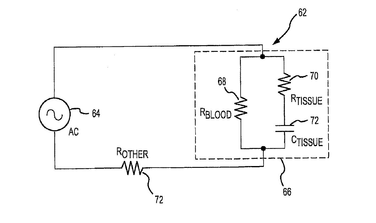
特定の用途に対し所望の周波数が選択されたものとすると、図4に示すモデルを、図4aに示すように簡略化した電気回路62としてさらに表すことができる。回路62において、発生器40は、AC源64として表現される。上述したように、電極・組織接触を評価するために使用される可能性のある低い周波数動作では、血液・組織界面におけるキャパシタンスおよび抵抗がインピーダンス測定値の優位を占める。したがって、他の容量効果、誘導効果および抵抗効果を無視してもよく、血液・組織界面における容量・抵抗効果を、回路62において抵抗器・コンデンサ(R−C)回路66によって表してもよい。
Given that the desired frequency has been selected for a particular application, the model shown in FIG. 4 can be further represented as a simplified
R−C回路66は、標的組織24のインピーダンスに対する抵抗効果および容量効果を表す抵抗器70およびコンデンサ72と並列である、血液のインピーダンスに対する抵抗効果を表す抵抗器68を含んでもよい。電極カテーテル14が標的組織24にまったくかまたはほとんど接触しない場合、血液の抵抗効果はR−C回路66に影響を与え、そのため、インピーダンス測定値にも影響を与える。しかしながら、電極カテーテル14が移動して標的組織24と接触すると、標的組織24の抵抗効果および容量効果はR−C回路66に影響を与え、そのためインピーダンス測定値も影響を与える。
The RC circuit 66 may include a
インピーダンス測定値に対する抵抗およびキャパシタンスの影響を、インピーダンスの定義に関連してより理解することができる。インピーダンス(Z)を以下のように表すことができる。
Z=R+jX
ここで、Rは、血液および/または組織からの抵抗であり、jは、項が+90°の位相角を有することを示す虚数であり、Xは、キャパシタンスとインダクタンスとの両方からのリアクタンスである。
The effect of resistance and capacitance on impedance measurements can be better understood with respect to impedance definitions. The impedance (Z) can be expressed as follows.
Z = R + jX
Where R is resistance from blood and / or tissue, j is an imaginary number indicating that the term has a phase angle of + 90 °, and X is reactance from both capacitance and inductance. .
上記式から、リアクタンス成分の大きさが、回路62の抵抗効果と容量効果との両方に応答することが観察される。この変形は、電極・組織界面における接触または結合のレベルに直接対応し、したがって、それを使用して、電極・組織接触または結合を評価してもよい。例として、電極カテーテル14が100kHzの周波数で動作し、主に血液と接触する場合、インピーダンスは純粋に抵抗性であり、リアクタンス(X)は0オームに近い。電極カテーテル14が標的組織に接触すると、リアクタンス成分は負になる。接触または結合のレベルが増大するに従い、リアクタンス成分はさらに負になる。
From the above equation, it is observed that the magnitude of the reactance component responds to both the resistance effect and the capacitance effect of the
別法として、接触状態または結合状態を、位相角に基づいて確定してもよい。実際には、用途によっては位相角に基づいて接触状態または結合状態を確定することが好ましい場合もあり、それは、位相角が、リアクタンスと抵抗との間の三角比として表されるためである。抵抗成分の大きさは、条件が変化すると(たとえば異なる患者に対する)異なる可能性があるが、位相角は、外部条件に対して影響を受けにくい傾向にある相対測定値である。 Alternatively, the contact state or coupling state may be determined based on the phase angle. In practice, depending on the application, it may be preferable to determine the contact or coupling state based on the phase angle because the phase angle is expressed as a trigonometric ratio between reactance and resistance. While the magnitude of the resistance component may vary as conditions change (eg, for different patients), the phase angle is a relative measurement that tends to be less sensitive to external conditions.
例示的な実施形態では、位相角を、インピーダンス測定値から(たとえば図3のプロセッサ50により)確定してもよい。すなわち、インピーダンスを以下のように表してもよい。
Z=|Z|∠φ
ここで、|Z|はインピーダンスの大きさであり、φは位相角である。
In an exemplary embodiment, the phase angle may be determined from impedance measurements (eg, by
Z = | Z | ∠φ
Here, | Z | is the magnitude of impedance, and φ is the phase angle.
項|Z|およびφを、さらに以下のように表してもよい。 The terms | Z | and φ may be further expressed as follows.
![]()
tanφ=X/R
![]()
位相角はまた、電極・組織界面における接触または結合のレベルに直接対応し、したがって、それを使用して、電極・組織接触または結合を評価してもよい。例として、電極カテーテル14が100kHzの周波数で動作し、主に血液と接触する場合、位相角はゼロ(0)に近い。電極カテーテル14が標的組織に接触すると、位相角は負になり、接触または結合レベルが増大するに従って位相角はさらに負になる。例示の目的で一例を表1に示す。
The phase angle also directly corresponds to the level of contact or coupling at the electrode-tissue interface and may therefore be used to evaluate electrode-tissue contact or coupling. As an example, if the
位相角を確定するためにインピーダンス測定値を使用してもよいが、代替実施形態では、測定回路42を、位相角を直接確定する位相検出回路として実装してもよい。図5に例示的な位相検出回路80を示す。位相検出回路80を、機能的構成要素に関連して示しかつ説明する。本発明を完全に理解するために特定のハードウェア構成は必要でないということに留意されたい。デジタルおよび/またはアナログハードウェアおよび/またはソフトウェアでの位相検出回路80の実装は、電子工学技術における当業者には本明細書における教示を熟知した後に容易に明らかとなろう。
Although impedance measurements may be used to determine the phase angle, in alternative embodiments, the
例示的な位相検出回路80は、電極・組織界面における電流および電圧を測定する電流センサ82および電圧センサ84を含んでもよい。電流測定値および電圧測定値は、位相比較器86に対する入力であってもよい。位相比較器86は、電圧測定値と電流測定値との間の位相の差に比例する直流(DC)出力電圧を提供する。
The exemplary
一実施形態では、電流センサ82を使用して切除電流を測定してもよい。センサは、切除ワイヤと直列であってもよい。たとえば、コイルクラフト(Coilcraft)社のCST1電流検知変圧器を切除ワイヤと直列に配置してもよい。別法として、電流ワイヤは、物理的な接続があってもなくても、電流センサの穴を貫通してもよい。さらに、切除電極と接地パッチとの間の電圧を検知してもよい。この電圧を、位相検知回路に供給することができるように減衰させてもよい。そして、位相検知回路は、電流および電圧を測定し、それらの間の位相角を確定し、後にそれは結合レベルと相関される。このように、切除電流を使用して、結合検知の目的でさらなる電流を投入するのではなく位相角を測定することができる。
In one embodiment,
任意に、電流測定値を、移相回路88により移相させることにより、測定電流と測定電圧との間の移相遅れを「補正する」ことによって位相比較器86の動作を容易にしてもよい。また任意に、位相比較器86からの出力を、位相調整回路90によって、使用されている接地パッチ46のタイプ等、外部要因を補償するように「補正」してもよい。さまざまなデバイス(たとえば図3におけるプロセッサ50および表示装置54)によって使用されるために出力を増幅する(たとえばミリボルトからボルト)信号スケーリング回路92を提供してもよい。
Optionally, the
切除中、測定されたインピーダンスとその成分の抵抗およびリアクタンスは、組織温度によって変化する。かかる状態では、組織温度の変化による変化は、切除中の損傷形成の測度を提供する。 During ablation, the measured impedance and its component resistance and reactance vary with tissue temperature. Under such conditions, changes due to changes in tissue temperature provide a measure of lesion formation during ablation.
図5に示す位相検出回路80は、一例として提供するものであり、限定するようには意図されていないことに留意されたい。電子工学技術における当業者は、本明細書の開示を熟知した後に、本発明の範囲から逸脱することなく他の実施態様を容易に提供することができる。
It should be noted that the
電極接触評価のための例示的なシステムについて説明したが、ここで、図6〜図8に示すブロック図を参照して例示的な動作モードをより理解することができる。図6は、接触または結合を検知するための位相角測定を示す例示的なブロック図100である。図7は、切除エネルギーおよび接触検知信号の両方が切除電極に同時に印加される場合の、切除中の位相角測定を示す例示的なブロック200図である。図8は、検知信号と切除電力とを切り替える、切除中の位相角測定を示す例示的なブロック図300である。図7および図8では、同様の要素を示すために、それぞれ200番代および300番代の参照番号を使用し、これらの要素を、図7および図8に関連して繰り返して説明はしない可能性がある。
Having described an exemplary system for electrode contact assessment, an exemplary mode of operation can now be better understood with reference to the block diagrams shown in FIGS. FIG. 6 is an exemplary block diagram 100 illustrating phase angle measurements for detecting contact or coupling. FIG. 7 is an
上述したように、接触または結合を検知する位相角方法は、(1)組織が血液より抵抗性かつ容量性であり、(2)測定された電極インピーダンスが直接の周囲の物質に大部分依存するという事実に基づく。このため、電極が血液から心筋まで移動する時、測定インピーダンスは増大し、位相角は0°から負の値まで変化する(容量性)。位相角は抵抗およびリアクタンス両方の相対項であるため、それを使用して接触または結合レベルを表してもよい。すなわち、電極が血液と接触している時、それは0°基線を提供し、より多くの接触または結合が確立されるに従い一層負になる。それはまた、カテーテル、器具類および生理学的可変要素の影響を最小限にする。 As described above, the phase angle method of detecting contact or binding is (1) tissue is more resistant and capacitive than blood, and (2) the measured electrode impedance is largely dependent on the immediate surrounding material. Based on the fact that. For this reason, when the electrode moves from the blood to the myocardium, the measured impedance increases and the phase angle changes from 0 ° to a negative value (capacitive). Since the phase angle is a relative term for both resistance and reactance, it may be used to represent the contact or coupling level. That is, when the electrode is in contact with blood, it provides a 0 ° baseline and becomes more negative as more contact or coupling is established. It also minimizes the effects of catheters, instruments and physiological variables.
位相角測定を、負荷の電圧(V)102および電流(I)104の両方をサンプリングし、それらの信号間の遅れを位相角として計算することによって行ってもよい。図6に示すように、検知信号106は、切除電極108と参照電極110との間に印加される。この検知信号106は、たとえば、わずかな振幅(<1mA)で50kHzと500kHzとの間であってもよい。
Phase angle measurements may be made by sampling both the voltage (V) 102 and current (I) 104 of the load and calculating the delay between those signals as the phase angle. As shown in FIG. 6, the
例示的な器具を、参照電極構成に応じて、限定されないがたとえば100kHz、400kHzおよび485kHzの周波数として動作させてもよい。電流104および電圧102の両方が検知される。これら2つの信号は、位相比較器112に送出され、電極108の接触または結合状態に対応する位相角が計算される。ブロック114において生位相角信号が調整されることにより、たとえばカテーテル、器具類および生物学的可変要素によってもたらされる位相角に対する外部の影響が補償される。それはまた、容易な解釈およびインタフェースのために調整された後、ブロック116において、表示または他の処理のために他の機器に出力される。
Exemplary instruments may be operated at frequencies of, for example, but not limited to 100 kHz, 400 kHz, and 485 kHz, depending on the reference electrode configuration. Both current 104 and
位相補償を、切除処置の開始時に行ってもよい。まず、カテーテル電極108を、血液にのみ接触するように、心腔(たとえば、右心房または左心房)の中央まで移動させる。システムは、位相角を測定し、ゼロ接触レベルに対する基線としてこの値を使用する。この調整により、カテーテル配線、参照電極の位置、および外部パッチが使用される場合は皮膚または脂肪等、カテーテルおよび患者によってもたらされる固定位相角が補償される。
Phase compensation may be performed at the beginning of the ablation procedure. First, the
初期ゼロ調整後、ユーザは、カテーテル電極を1つまたは複数の所望の部位まで移動させて不整脈の心筋を切除してもよい。例示的な実施形態では、位相角は、電極108が心筋からたとえば3mm以内まで近づくと変化を開始し、さらに接触または結合が確立されるに従いますます負になる。ユーザは、切除エネルギーを与える前に位相角出力に基づいて電極的接触または結合の質を判断してもよい。例示的な実施形態では、この位相角値は、4mm切除電極が実際に心筋に接触する場合、約−3°である。ここで図7および図8に関連してさらに詳細に説明するように、切除中に位相角を測定する少なくとも2つの方法があることに留意されたい。
After initial zeroing, the user may move the catheter electrode to one or more desired sites to remove the arrhythmic myocardium. In an exemplary embodiment, the phase angle begins to change as the
図7において、電極208に切除電力218が印加される一方で、同様に検知信号206が印加される。切除および接触検知は、異なる周波数で動作する。したがって、フィルタリングにより、心筋の切除を妨げることなく切除中に位相角を測定することができる。
In FIG. 7, the
別のオプションは、図8においてスイッチ320によって示すように、検知信号306と切除電力318との間の位相測定を切り替える、というものである。接近中に切除電力318がオフにされると、振幅の小さい検知信号306がオンにされ、それを使用して接触または結合を検知するための位相角が測定される。切除処置のために切除電力318がオンにされると、振幅の大きい切除電力318の電圧および電流が、切除中の接触または結合指標として検知され使用される。
Another option is to switch the phase measurement between the
図9aは、電極結合評価プロトコル400(以下、「評価プロトコル400」)の一実施形態を示し、これを使用して、この評価が位相角に基づく場合、電極(たとえばカテーテル電極)の任意の適当な組織との結合を評価することができる。したがって、プロトコル400を、図6〜図8に関連して上述した実施形態に関連して使用してもよい。いずれの場合も、「結合」は、電極の標的組織との電気的結合、電極と標的組織との間の機械的結合またはその両方を含んでもよい。
FIG. 9a illustrates one embodiment of an electrode coupling evaluation protocol 400 (hereinafter “
図9aの評価プロトコル400のステップ402は、電気信号を電極に送出することに関する。通常、これを、電極が少なくとも標的組織に概して近接して(たとえば左心房等の心腔内)に配置された後に行う。その後、ステップ404において位相角を確定し、その後、ステップ408においてこの位相角に基づいて電極結合を評価する。ステップ408からの電極結合評価を、ステップ410を実行することにより分類してもよい。しかしながら、すべての場合においてステップ410の分類が必要であるとは限らない。いずれの場合も、ステップ412に従って、ステップ408からの評価の結果を出力する。
Step 402 of the
プロトコル400のステップ402に従って送出される電気信号は、任意の適当な周波数であってもよい。しかしながら、プロトコル400の目的で評価を行うためには単一の周波数のみでよい。ステップ404に関連する位相角は、インピーダンスの位相角であってもよい。この位相角を、たとえば任意の適当な構成の位相検知回路を使用して、任意の適当な方法で確定してもよい。一実施形態では、かつステップ402に関連する電気信号を使用して、電極の電流を測定し、電極と別の電極(たとえば戻り電極)との間の電圧を測定し、その後、これら電流測定値と電圧測定値との間の位相角を確定することにより、位相角を確定する。別のオプションは、リアクタンスおよびインピーダンスを適当な方法で測定/確定することと、その後、これらの値から位相角を確定する(たとえば、位相角の正弦はリアクタンスのインピーダンスに対する比である)ことと、である。
The electrical signal sent in accordance with
位相角を、RCLメータまたは位相検出回路(たとえば、発振器、マルチプレクサ、フィルタ、位相検出回路を有する)を使用して確定してもよく、それを位相モジュールと呼んでもよい。この位相モジュール(測定および/または検出)を、カテーテルハンドルセットに組み込むかまたは埋め込むことにより、切除カテーテルと電源との間の独立形ユニットの形態とすることにより、電源に組み込むかまたは埋め込むことにより、電気生理学またはEPマッピングシステムに組み込むことにより、もしくは電気生理学記録システムの一部とすること等により、任意の適当な場所に配置してもよい。 The phase angle may be determined using an RCL meter or a phase detection circuit (eg, having an oscillator, multiplexer, filter, phase detection circuit), which may be referred to as a phase module. By incorporating or embedding this phase module (measurement and / or detection) in the power supply by incorporating or embedding it in the catheter handle set, in the form of a stand-alone unit between the ablation catheter and the power supply, It may be placed in any suitable location, such as by being incorporated into an electrophysiology or EP mapping system, or as part of an electrophysiology recording system.
電極の組織との結合の評価(プロトコル400のステップ408)を、任意の適当な方法で行ってもよい。たとえば、ステップ404を通して確定される位相角を、1つまたは複数のベンチマーク位相角値と(たとえば位相角比較器を使用して)比較してもよい。これらベンチマーク位相角値を、任意の適当な方法で、たとえば実験的に確定し/設定してもよい。これらベンチマーク位相角値を、適当なデータ構造に、たとえばコンピュータ可読データ記憶媒体に格納してもよく、もしくは位相角比較器に利用可能となるようにしてもよい。概して、かつ一実施形態では、位相角は、電極・組織(たとえば心筋)が結合するにしたがって低減する。
Assessment of electrode binding to tissue (step 408 of protocol 400) may be performed in any suitable manner. For example, the phase angle determined through
図9aの評価プロトコル400のステップ410の分類の目的のために、以下の状態のうちの1つまたは複数に対して1つまたは複数のベンチマーク位相角値(たとえば、単一ベンチマーク位相角値またはある範囲のベンチマーク位相角値)があってもよい。すなわち、1)不十分な電極結合(たとえば、「A」を下回る関連位相角が不十分な電極結合に相当するものとされる電極結合)、2)十分な電極結合(たとえば、関連位相角が「A」を上回りかつ「B」を下回る電極結合が十分な電極結合に相当するものとされる)および3)高電極結合または過度な電極結合(たとえば、「B」を上回る関連位相角が高電極結合または過度な電極結合に相当するものとされる電極結合)である。一実施形態は、以下の位相角値が示した状態に相当するものとする。
不十分な電極結合: Φ>−5°
十分な電極結合: −5°>Φ>−10°
高/過度な電極結合: Φ<−10°
For the purposes of the classification of
Insufficient electrode coupling: Φ> -5 °
Sufficient electrode coupling: −5 °>Φ> −10 °
High / excessive electrode coupling: Φ <−10 °
「高」電極結合または「過度な」電極結合は、電気的結合、機械的結合または両方(電極と標的組織との間の結合)に関連して高い/過度であり得る。一実施形態では、高い/過度なまたは堅固な電極結合は、電極と標的組織との間の高い/過度な機械的接触を意味する。種々の理由で高機械的接触または過度な機械的接触が電極と組織との間に存在する時を知ることが望ましい場合がある。たとえば、電極と標的組織との間の高機械的接触または過度な機械的接触を回避することが望ましい場合もある(たとえば、電極を、組織壁、膜等内に向ける可能性を低減するため)。しかしながら、電極により標的組織に対し十分な機械的力が加えられる時を知ることが望ましい場合もある(たとえば、電極を、組織壁、膜等内に向ける可能性を増大させることによりこの組織壁または膜の他方の側の所望の領域にアクセスすることができるようにするため)。 “High” electrode coupling or “excessive” electrode coupling may be high / excessive in relation to electrical coupling, mechanical coupling, or both (coupling between the electrode and the target tissue). In one embodiment, high / excessive or firm electrode coupling means high / excessive mechanical contact between the electrode and the target tissue. It may be desirable to know when high or excessive mechanical contact exists between the electrode and tissue for various reasons. For example, it may be desirable to avoid high or excessive mechanical contact between the electrode and the target tissue (eg, to reduce the possibility of directing the electrode into a tissue wall, membrane, etc.). . However, it may be desirable to know when sufficient mechanical force is applied to the target tissue by the electrode (e.g., this tissue wall or To be able to access the desired area on the other side of the membrane).
ステップ408の評価の結果を、図9aの電極結合評価プロトコル400のステップ412に従う任意の適当な方法で出力してもよい。任意の適当な出力を、たとえば視覚的に(たとえば棒グラフ、もしくは任意の適当な位置または位置の組合せにおける他の任意の適当な表示)、音声で(たとえばアラーム)、物理的に(たとえば、電極に基づく処置を行う医師によって保持されているハンドルを振動させることにより、かつ本明細書においてより詳細に説明するように)またはそれらの任意の組合せにより、利用してもよい。単一出力を提供してもよい。2つ以上の出力の組合せを利用してもよい。1つまたは複数の出力を単一場所にまたは複数の場所に発行してもよい。
The result of the evaluation of
図9bは、電極結合評価プロトコル400’の一実施形態を示し、これを使用して電極(たとえばカテーテル電極)の任意の適当な組織との結合を評価してもよく、この場合、この評価はリアクタンスに基づく。プロトコル400’は図9aのプロトコル400の変形であるため、図9bのプロトコル400’の個々のステップを識別する参照数字に関連して「単一プライム」指示を使用する。
FIG. 9b shows one embodiment of an electrode
図9bの評価プロトコル400’のステップ402’は、電気信号を送出することに関する。プロトコル400’に対し、その評価を提供するためには単一周波数のみでよい。すなわち、評価プロトコル400’の場合、単一周波数を使用して電極結合評価を提供してもよい。通常、これを、電極が少なくとも概して標的組織の近傍(たとえば心腔内)に配置された後に行う。その後、ステップ404’において、電極および標的組織を含む電気回路のリアクタンスを確定する。このリアクタンスを、任意の適当な方法で確定してもよい。たとえば、位相角を測定してもよく(たとえば上述したことに従って)、インピーダンスを測定してもよく、これら2つの値からリアクタンスを計算してもよい(たとえば、位相角の正弦はリアクタンスのインピーダンスに対する比に等しい)。リアクタンスを確定するための別のオプションは、パルス波の位相または周波数応答を確定することである。 Step 402 'of the evaluation protocol 400' of FIG. 9b relates to sending an electrical signal. For protocol 400 ', only a single frequency is required to provide its evaluation. That is, in the case of the evaluation protocol 400 ', a single frequency may be used to provide an electrode coupling evaluation. This is typically done after the electrode has been placed at least generally near the target tissue (eg, in the heart chamber). Thereafter, in step 404 ', the reactance of the electrical circuit including the electrode and the target tissue is determined. This reactance may be determined in any suitable manner. For example, the phase angle may be measured (eg, as described above), the impedance may be measured, and the reactance may be calculated from these two values (eg, the sine of the phase angle is relative to the impedance of the reactance) Equal to the ratio). Another option for determining the reactance is to determine the phase or frequency response of the pulse wave.
プロトコル400’のステップ408’において、上述したリアクタンスに基づいて電極結合を評価する。ステップ408’からのこの電極結合を、ステップ410’を実行することによって分類してもよい。しかしながら、すべての場合においてステップ410’の分類が必要であるとは限らない。いずれの場合も、ステップ412’に従って評価の結果を出力する。ステップ412’は、図9aの電極結合評価プロトコル400のステップ412に一致してもよい。
In step 408 'of protocol 400', electrode coupling is evaluated based on the reactance described above. This electrode combination from step 408 'may be classified by performing step 410'. However, the classification of step 410 'is not necessarily required in all cases. In either case, the evaluation result is output in accordance with step 412 '. Step 412 'may correspond to step 412 of the electrode
電極の組織との結合の評価(プロトコル400’のステップ408’)を、任意の適当な方法で行ってもよい。たとえば、ステップ404’を通して確定されるリアクタンスを、1つまたは複数のベンチマークリアクタンス値と(たとえばリアクタンス比較器を使用して)比較してもよい。これらベンチマークリアクタンス値を、任意の適当な方法で、たとえば実験的に確定/設定してもよい。これらベンチマークリアクタンス値を、適当なデータ構造、たとえばコンピュータ可読データ記憶媒体に格納してもよく、もしくはリアクタンス比較器に利用可能となるようにしてもよい。概してかつ一実施形態では、電極・組織(たとえば心筋)が結合するほどリアクタンスが低減する。 Assessment of electrode binding to tissue (step 408 'of protocol 400') may be performed in any suitable manner. For example, the reactance determined through step 404 'may be compared (eg, using a reactance comparator) with one or more benchmark reactance values. These benchmark reactance values may be determined / set in any suitable manner, for example experimentally. These benchmark reactance values may be stored in a suitable data structure, such as a computer readable data storage medium, or made available to a reactance comparator. In general and in one embodiment, the reactance decreases as the electrode / tissue (eg, myocardium) is coupled.
ステップ410’の分類の目的で、以下の状態のうちの1つまたは複数に対し1つまたは複数のベンチマークリアクタンス値(たとえば単一のベンチマークリアクタンス値またはある範囲のベンチマークリアクタンス値)があってもよい。すなわち、1)不十分な電極結合(たとえば、「A」を下回る関連リアクタンスが不十分な電極結合に相当するものとされる電極結合)、2)十分な電極結合(たとえば、関連リアクタンスが「A」を上回りかつ「B」を下回る電極結合が十分な電極結合に相当するものとされる)および3)高電極結合または過度な電極結合(たとえば、「B」を上回る関連リアクタンスが高電極結合または過度な電極結合に相当するものとされる電極結合)である。一実施形態は、以下のリアクタンス値が示した状態に相当するものとする。
不十分な電極結合: X>−5
十分な電極結合: −5>X>−15
高/過度な電極結合: X<−15
For classification purposes in
Insufficient electrode coupling: X> -5
Sufficient electrode coupling: -5>X> -15
High / excessive electrode coupling: X <-15
電極結合評価を位相角に基づかせる1つの利益は、位相角は、単独でまたは個々に考慮したインピーダンスまたはリアクタンスより、患者間の変化または動作設定に対して影響を受け難いということである。電極結合評価を提供するために、組織間の変化またはかかる他の状態に対する感度を低減させる他の方法を利用してもよい。図9cは、電極結合評価プロトコル480、すなわち電極(たとえばカテーテル電極)の任意の適当な組織との結合を評価するために使用され得るプロトコル480のかかる実施形態を示す。評価プロトコル480のステップ482は、電極に一定周波数の電極信号を送出することに関する。ステップ484において少なくとも1つの電気パラメータを測定する。そして、ステップ486において、この測定値から、「インピーダンス成分比」として特徴付けてもよいものを確定する。「インピーダンス成分比」という句は、位相角等、インピーダンスの2つの個々の成分の比である任意の項を意味する(位相角の正接はリアクタンスの抵抗に対する比に等しい)。インピーダンス成分比を、単に位相角を測定することによる等、任意の適当な方法で確定してもよい。インピーダンス成分比を確定する他の方法には、限定されないが、ステップ482に含まれる周波数での抵抗およびリアクタンスを確定することと、これら2つのパラメータからインピーダンス成分比を計算することと、が含まれる。インピーダンスに関連する2つの成分の比を使用することにより、電極結合評価、すなわち電極と標的組織との間の結合の評価に対し、組織間の変化に対する感度を低減することができる。
One benefit of basing the electrode coupling assessment on the phase angle is that the phase angle is less sensitive to changes or operating settings between patients than alone or individually considered impedance or reactance. Other methods that reduce sensitivity to changes between tissues or other such conditions may be utilized to provide an electrode coupling assessment. FIG. 9c shows such an embodiment of an electrode
プロトコル480のステップ488において電極結合を評価する。ステップ488からのこの電極結合を、ステップ490を実行することによって分類してもよく、ステップ490は、図9aに関連して上述した電極結合評価プロトコル400のステップ410に従ってもよい。したがって、すべての場合においてステップ490の分類が必要であるとは限らない。いずれの場合も、評価の結果を、ステップ492に従って出力する。ステップ492は、図9aに関連して上述した電極結合評価プロトコル400のステップ412にしたがってもよい。
In
図9a〜図9cのプロトコルの各々は、電極結合が、電極と標的組織との間の機械的結合(すなわち物理的接触)であることと、電気的結合(たとえば、電気エネルギーの十分な部分が電極から標的組織にまで渡る状態)であることと、を含む。機械的結合があるときはいつでも、電気的結合がある。しかしながら、逆は真ではない。電極が標的組織と接触することなく、電気的結合があり得る。図10は、電極414と標的組織416との間に機械的接触のない電気的結合がある場合の代表的な一例を示す。ここでは、電極414は組織416の表面上の空隙418内に配置され、空隙418は、電極414と標的組織416との間の電気的結合を提供する。したがって、図9a〜図9cのプロトコルの各々は、電極と標的組織との間の機械的接触を必要としない電気的結合を示してもよい。
Each of the protocols of FIGS. 9a-9c shows that the electrode coupling is a mechanical coupling (ie, physical contact) between the electrode and the target tissue and that electrical coupling (eg, a sufficient portion of electrical energy is A state extending from the electrode to the target tissue). Whenever there is mechanical coupling, there is electrical coupling. However, the converse is not true. There can be electrical coupling without the electrode contacting the target tissue. FIG. 10 shows a representative example where there is an electrical coupling without mechanical contact between the
図11a〜図11cは、電極結合評価を提供することに関連して使用され得るさまざまな構成を概略的に提示する。これらのシステムの各々について切除電極に関連して説明するが、電極結合評価を、電極が任意の適当な機能または機能の組合せを提供する任意の適当な用途に使用してもよい。図11a〜図11cのシステムの各々を使用して、図9a〜図9cに関連して上述した評価プロトコルを提供してもよい。また、これら構成を商用的に実装するために、フィルタ(たとえば、結合評価を行うために使用されている電流から分離されるべき1つまたは複数の他の発生源からの電流があり得る場合のように)、患者を「電気的に保護する」1つまたは複数の構成要素および/または電極結合評価を行うために使用される電気回路等、他のさまざまな構成要素を利用することが望ましい場合もあることが理解されるべきである。 FIGS. 11a-11c schematically present various configurations that may be used in connection with providing an electrode coupling assessment. Although each of these systems will be described in the context of an ablation electrode, electrode coupling assessment may be used for any suitable application where the electrode provides any suitable function or combination of functions. Each of the systems of FIGS. 11a-11c may be used to provide the evaluation protocol described above in connection with FIGS. 9a-9c. Also, to implement these configurations commercially, there may be currents from one or more other sources that should be separated from the currents that are used to perform the coupling evaluation (e.g. As well) where it is desirable to utilize one or more components that "electrically protect" the patient and / or various other components, such as electrical circuits used to perform electrode coupling assessments It should be understood that there are also.
図11aは、切除電源424、切除電極422および戻り電極426を含む切除システム420を示す。切除電源424によって任意の適当な周波数が使用されてもよい。切除電極422および戻り電極426の各々は、任意の適当なサイズ、形状および/または構成であってもよい。通常、切除電極422は、患者の身体内に配置されるカテーテル電極の形態となる。戻り電極426を、任意の適当な位置してもよい(たとえば、患者の皮膚の上に配置される接地パッチ、患者の身体内に配置されるカテーテル電極)。
FIG. 11 a shows an
切除システム420の追加の構成要素には、電極結合評価電源428(以下、「評価電源428」)、評価戻り電極430および電極結合評価モジュール432(以下、「評価モジュール432」)が含まれる。評価電源428によって任意の適当な周波数が使用されてもよい。通常、切除電源424はまた、評価電源428より大幅に高い電流を使用する。
Additional components of the
評価戻り電極430は、任意の適当なサイズ、形状および/または構成であってもよく、任意の適当な位置に配置されてもよい。一実施形態では、戻り電極426および評価戻り電極430は、異なる位置に配置される別々の構造の形態である。別の実施形態では、単一構造(戻り電極426としてかつ評価戻り電極430として機能する単一ユニット)により、戻り電極426の機能と評価戻り電極430の機能とが提供される。
切除電極422は、切除システム420に対するスイッチ434の位置に応じて、切除電源424または評価電源428いずれかからの電力を受け取る。すなわち、図11aの切除システム420の場合、切除動作および電極結合評価動作は同時に行われない可能性がある。電極結合評価動作中、スイッチ434は、当然ながら、評価電源428からの電力を受け取るように配置される。これにより、評価モジュール432は、切除電極422と標的組織との間の結合を評価することができる。評価モジュール432により、その電極結合評価機能を提供するために、限定なしに本明細書で扱うさまざまな構成(たとえば位相角比較に基づく評価、リアクタンス比較に基づく評価、インピーダンス成分比比較に基づく評価、図12aおよび図12bに関連して後述するような0°位相周波数または0インダクタンス周波数に関連する周波数を識別することに基づく評価)を含む、任意の適当な構成を利用してもよい。評価モジュール432は、単一周波数から図9a〜図9cのプロトコルのいずれかを使用する電極結合評価を提供してもよい。
The
図11bは、切除電源444、切除電極442および戻り電極446を含む切除システム440を示す。切除電源444により任意の適当な周波数が使用されてもよい。切除電極442および戻り電極446の各々は、任意の適当なサイズ、形状および/または構成であってもよい。通常、切除電極442は、患者の身体内に配置されるカテーテル電極の形態となる。戻り電極446を、任意の適当な位置に配置してもよい(たとえば、患者の皮膚の上に配置される接地パッチ、患者の身体内に配置されるカテーテル電極)。
FIG. 11 b shows an
切除システム440の追加の構成要素には、電極結合評価電源448(以下、「評価電源448」)、評価戻り電極450および電極結合評価モジュール452(以下、「評価モジュール452」)が含まれる。評価電源448によって任意の適当な周波数が使用されてもよい。しかしながら、切除システム440の場合、切除動作および電極結合評価動作の同時実行に適応するために、切除電源444および評価電源448は異なる周波数で動作する。さらに、通常、切除電源444はまた、評価電源448より大幅に高い電流を使用する。
Additional components of the
評価戻り電極450は、任意の適当なサイズ、形状および/または構成であってもよく、任意の適当な位置に配置されてもよい。一実施形態では、戻り電極446および評価戻り電極450は、異なる位置に配置される別々の構造の形態である。別の実施形態では、単一構造(戻り電極446としてかつ評価戻り電極450として機能する単一ユニット)により、戻り電極446の機能と評価戻り電極450の機能とが提供される。
The
切除電極442は、切除電源444または評価電源448から同時に電力を受け取る。すなわち、図11bの切除システム440の場合、切除動作および電極結合評価動作が同時に行われ得る。これに関して、切除電源444および評価電源448はこの場合もまた、異なる周波数で動作する。評価モジュール452は、単一周波数から図9a〜図9cのプロトコルのいずれかを使用する電極結合評価を提供してもよい。いずれの場合も、評価モジュール452は、切除電極442と標的組織との間の結合を評価する。図11aの切除システム420に対する評価モジュール432に関連して上述した説明は、図11bの切除システム440に対する評価モジュール452に対して等しく適用可能である。
The
図11cは、切除電源464、切除電極462および戻り電極466を含む切除システム460を示す。切除電源464によって任意の適当な周波数が使用されてもよい。切除電極462および戻り電極466の各々は、任意の適当なサイズ、形状および/または構成であってもよい。通常、切除電極462は、患者の身体内に配置されるカテーテル電極の形態となる。戻り電極466を、任意の適当な位置してもよい(たとえば、患者の皮膚の上に配置される接地パッチ、患者の身体内に配置されるカテーテル電極)。
FIG. 11 c shows an
切除システム460の追加の構成要素には、電極結合評価電源468(以下、「評価電源468」)が含まれる。評価電源468によって任意の適当な周波数が使用されてもよい。通常、切除電源464はまた、評価電源468より大幅に高い電流を使用する。
Additional components of the
切除システム460は、一対の電極結合評価モジュール472a、472b(以下、「評価モジュール472a」および「評価モジュール472b」)をさらに含む。評価モジュール472aは評価電源468に関連し、評価モジュール472bは切除電源464に関連する。図示する実施形態では、切除動作および電極結合評価動作はともに戻り電極466を利用するが、上述した図11aおよび図11bの実施形態の場合のように別々の戻り電極を利用することも可能であり得る。
The
切除電極462は、切除システム460に対するスイッチ474の位置に応じて、切除電源464または評価電源468のいずれかから電力を受け取る。しかしながら、図11aの実施形態とは異なり、電極結合評価動作を、スイッチ474の位置とは無関係に実行してもよい。切除電極462が、スイッチ474を通して評価電源468と電気的に相互接続される場合、評価モジュール472aを使用して切除電極462と標的組織との間の結合が評価される。切除電極462がスイッチ474を通して切除電源464に電気的に相互接続される場合、評価モジュール472bを使用して、切除電極462と標的組織との間の結合が評価される。評価モジュール427a、472bは各々、単一周波数から図9a〜図9cのプロトコルのいずれかを使用する電極結合評価を提供してもよい。
The
評価モジュール472a、472bにより、それらのそれぞれの電極結合評価機能を提供するために、限定なしに本明細書で扱うさまざまな構成を含む任意の適当な構成を利用してもよい。図11aの切除システム420に対する評価モジュール432に関連して上述した説明は、図11cの切除システム460に対する評価モジュール472a、472bに等しく適用可能である。通常、評価モジュール472a、472bは、電極結合を評価することに対して同じ構成であるが、すべての場合においてそうであるとは限らない。評価モジュール472a、472bが同じ構成である場合、切除電源464および評価電源468は通常同じ周波数で動作する。したがって、切除システム460は、切除動作を開始する(たとえば評価電流および評価モジュール472aを使用して)前に電極結合の評価に対応し、さらに、切除動作中に電極結合の評価に対応する(たとえば、実際の切除電流対小さい方の電流を使用し、かつ評価モジュール472bを使用して)。図11bの切除システム440はまた、切除動作中の電極結合の評価に対応するが、別々の評価電流対実際の切除電流を使用する。
Any suitable configuration may be utilized by the evaluation modules 472a, 472b to provide their respective electrode coupling evaluation functions, including various configurations addressed herein without limitation. The description given above in connection with the
図11a〜図11cの実施形態の各々における評価モジュールによって使用される電極のうちの1つは、当然ながら切除または「活性」電極である。電極結合評価モジュールおよび切除電極はともに、それらのそれぞれの機能を提供するために、何らかの方法で患者とインタフェースする別の電極が必要である。図1aは、評価モジュールによって使用される戻り電極と、1つまたは複数の所望の機能を提供するために組織に電気エネルギーを提供するように切除電極と協働する戻り電極と、が、共通の構造に組み込まれる一実施形態を示す。より詳細には、切除電極20(たとえばカテーテル電極)は、心臓16の腔(たとえば左心房)に配置され、カテーテル電極20の形態である。戻り電極20a(たとえばカテーテル電極)もまた心臓16の同じ腔に配置され、図11a〜図11cの評価モジュールの各々によって使用され(切除電極20の標的組織24との結合を評価するため)、かつ切除電極20によって使用され得る(所望の医療機能を提供するために標的組織24に電気エネルギーを送達するため)。したがって、切除電極20および戻り電極20aを、異なるカテーテルに関連付けてもよく、それにより、個々に移動させてもよい。一実施形態では、戻り電極20aは切除電極20より広い表面積を有する。切除電極20および戻り電極20aの各々は、互いに間隔が空けられた電極先端を有する。
One of the electrodes used by the evaluation module in each of the embodiments of FIGS. 11a-11c is of course an ablation or “active” electrode. Both the electrode coupling evaluation module and the ablation electrode require separate electrodes that interface with the patient in some way to provide their respective functions. FIG. 1a illustrates a common use of a return electrode used by an evaluation module and a return electrode that cooperates with an ablation electrode to provide electrical energy to tissue to provide one or more desired functions. 1 illustrates one embodiment incorporated into a structure. More specifically, the ablation electrode 20 (eg, a catheter electrode) is disposed in the cavity of the heart 16 (eg, the left atrium) and is in the form of a catheter electrode 20. A
図1aに示す構成は、共通の心腔に2つの電極20、20aを提供する。別のオプションは、2つ以上の電極が共通のカテーテルに関連するが、カテーテルは2つの分離された遠位部を有し、各々その遠位端の別々の電極先端に電極を有し、それにより、電極先端が互いから間隔が空けられる、というものである。
The configuration shown in FIG. 1a provides two
活性電極と標的組織との間の結合を評価するために位相角を使用する1つまたは複数の方法について上に提示した。電極結合を評価するために位相角を使用してもよい別の方法を図12aおよび図12bに示す。図12aは、可変周波数源502、電気パラメータ測定モジュール504、電極結合評価モジュール506、および所望の機能または機能の組合せ(たとえば切除)を提供するために組織510に結合される電極508を含む、電極結合評価システム500の概略図を提示する。図12aには戻り電極を示さないが、それは、任意の適当なタイプであってもよく、かつ任意の適当な場所に配置されてもよい。概して、可変周波数源502は、電気エネルギーを組織510に送出する目的で、電極508に電気信号を提供する。電気パラメータ測定モジュール504は、任意の適当なタイプおよび/または構成であってもよく、1つまたは複数の電気パラメータを測定し、電極結合評価モジュール506によって使用される情報を提供する。電極結合評価モジュール506は、電極508と組織510との間の結合を評価する。
One or more methods using phase angle to evaluate the binding between the active electrode and the target tissue are presented above. Another method in which the phase angle may be used to evaluate electrode coupling is shown in FIGS. 12a and 12b. FIG. 12a illustrates an electrode comprising a
図12bは、図12aの電極結合評価モジュール506によって使用され得る電極結合プロトコル520の一実施形態を提示する。ステップ524を実行することにより、電極508に1つまたは複数の電気信号を送出する。基線結合状態を評価することができる。たとえば、プロトコル520のステップ524〜528に従って、基線結合状態を定義することができる。「基線結合状態」という用語は、媒体(たとえば血液)における所望の周波数でのゼロ化位相角またはゼロ化リアクタンスを含む。
FIG. 12b presents one embodiment of an
ステップ525を実行することにより、電極が所望の媒体、たとえば血液にある時を確定する。次に、ステップ526を実行することにより、基線結合状態を確立する。たとえば、医師は、基線結合状態の確立を指示するように入力デバイスを起動することができる。そして、プロトコル520は、ステップ528において、位相角またはリアクタンスをゼロに補正することにより基線結合状態に調整する。
By performing
基線結合状態をゼロにすることに対する代替態様として、ステップ526で確立された基線結合状態の値を格納し、かかる基線結合状態に対する電極結合状態を確定するために使用してもよい。第2の代替態様では、確定された位相角を1つまたは複数の所定ベンチマーク値と比較することにより、基線結合状態を確定してもよい。これらベンチマーク値を、任意の適当な方法で、たとえばインビトロ(in vitro)検査、エクスビボ(ex vivo)検査またはインビボ(in vivo)検査で実験的に確定し/設定してもよい。これらベンチマーク値を、適当なデータ構造に、たとえばコンピュータ可読データ記憶媒体に格納してもよく、もしくは位相比較器に利用可能となるようにしてもよい。
As an alternative to setting the baseline coupling state to zero, the baseline coupling state value established in
電極結合を、ステップ528からの基線結合状態を使用してプロトコル520のステップ532に従って評価してもよい。1つまたは複数の電気パラメータを任意の適当な方法で確定し、ステップ528からの基線結合状態の対応する値と比較してもよい。たとえば、以下のカテゴリを提供してもよい。すなわち、1)不十分な電極結合(たとえば、「A」を下回る基線結合状態に関連する値が不十分な電極結合に相当するものとされる電極結合)、2)十分な電極結合(たとえば、基線結合状態が「A」を上回りかつ「B」を下回る基線結合状態に関連する値が十分な電極結合に相当するものとされる)および3)高電極結合または過度な電極結合(たとえば、「B」を上回る基線結合状態に関連する値が高電極結合または過度な電極結合に相当するものとされる電極結合)である。
Electrode coupling may be evaluated according to step 532 of
別の実施形態では、電気的結合を、「標的周波数」、すなわち電気パラメータに対する事前設定値(たとえば事前設定リアクタンスまたは位相角値)に対応する周波数の関数として測定する。図12cは、図12aの電極結合評価モジュール506によって使用され得る電極結合プロトコル620の一実施形態を提示する。ステップ624を実行することにより電極508に電気信号を送出する。電気信号を異なる周波数で送出する。送出される各周波数において、ステップ626は、リアクタンスおよび/または位相を測定する。ステップ628は、測定されたリアクタンスまたは位相を事前設定値と比較する。リアクタンスまたは位相が事前設定値と一致する周波数が「標的周波数」である。ステップ628の目的のための事前設定値に対し、正の値、ゼロまたは負の値を含む任意の適当な値を使用してもよい(たとえば、標的周波数を0°位相周波数と呼んでもよいように、ゼロ位相角、または標的状態周波数を0インダクタンス周波数と呼んでもよいように、ゼロインダクタンス)。
In another embodiment, electrical coupling is measured as a function of frequency corresponding to a “target frequency”, ie, a preset value for an electrical parameter (eg, a preset reactance or phase angle value). FIG. 12c presents one embodiment of an
プロトコル620は、標的周波数が存在すると確定すると、ステップ630に進み、そこで、ステップ628によって提供された情報を使用して、電極508の組織510との結合を評価し、プロトコル620のステップ636に従って、この評価の結果を出力する。ステップ636は、図9aに関連して上述したプロトコルのステップ412に従ってもよい。
If the
組織との電極結合の評価を、図12cのプロトコル620のステップ630を通して提供する。ステップ628からの標的周波数を、1つまたは複数のベンチマーク周波数値と(たとえば比較器を使用して)比較してもよい。これらベンチマーク周波数値を、任意の適当な方法で確定し/設定してもよい。値を、たとえばインビトロ検査、エクスビボ検査またはインビボ検査で実験的に事前確定することができる。これらベンチマーク周波数値を、適当なデータ構造に、たとえばコンピュータ可読データ記憶媒体に格納してもよい。ベンチマーク周波数値を、医師が処置中に確定してもよい。たとえば、電極が所望の媒体、たとえば血液にある時を確定してもよい。その時点で、医師は、既存の結合関連状態に対しベンチマーク値を設定するように入力デバイスを起動することができる。
An assessment of electrode binding to tissue is provided through
図12cの評価プロトコル620の分類の目的のための以下の状態のうちの1つまたは複数に対して1つまたは複数のベンチマーク周波数値(たとえば、単一ベンチマーク周波数値またはある範囲のベンチマーク周波数値)があってもよい。すなわち、1)不十分な電極結合(たとえば、「A」を下回る標的周波数が不十分な電極結合に相当するものとされる電極結合)、2)十分な電極結合(たとえば、標的周波数が「A」を上回りかつ「B」を下回る電極結合が十分な電極結合に相当するものとされる電極結合)および3)過度な電極結合(たとえば、「B」を上回る標的周波数が過度な電極結合に相当するものとされる電極結合)である。一実施形態は、以下の標的周波数値が示した状態に相当するものとする(Ftは示した状態に対する標的周波数である)。
不十分な電極結合: Ft<120kHz
十分な電極結合: 120kHz<Ft<400kHz
高/過度な電極結合: Ft>400kHz
One or more benchmark frequency values (eg, a single benchmark frequency value or a range of benchmark frequency values) for one or more of the following states for the purposes of classification of
Insufficient electrode coupling: F t <120 kHz
Sufficient electrode coupling: 120 kHz <F t <400 kHz
High / excessive electrode coupling: F t > 400 kHz
図12cのプロトコル620を、任意の適当な方法で実装してもよい。たとえば、インピーダンスを監視して、信号周波数を掃引することにより(たとえば図12aのシステム500に従って)標的位相周波数を取得してもよい。この周波数掃引を、2つの適当な値(たとえば50kHzおよび1MHz)の間で、掃引に対するこれらの値の間の任意の適当な増分変化(たとえば、10〜20kHz増分)を使用して、提供してもよい。この手法は、一度に1つの周波数でインピーダンスを測定しそれら周波数を周波数合成器等によって回転させることを含む、周波数スイッチングと呼ばれ得るものを使用する。別の手法は、複数の周波数を結合し、結合された信号からフィルタリングを通して個々の周波数の各々におけるインピーダンスを確定する、というものである。場合によっては標的周波数状態に関連する周波数を確定するために補間が必要となる可能性があることが理解されるべきである(たとえば、プロトコル620によって使用される2つの周波数の間に標的周波数状態に関連する周波数が存在することが確定される場合)。
The
本発明のいくつかの実施形態を、ある程度の特定性で上述したが、当業者は、本発明の趣旨または範囲から逸脱することなく開示した実施形態に対し多くの変更を行うことができる。本発明の読み手の理解を助けるために識別の目的でのみ参照符号を使用しており、それらは、発明の位置、向きまたは使用に関して限定をもたらすものではない。上記説明に含まれるかまたは添付図面に示されるすべての事柄が、限定としてではなく単に例示するものとして解釈されるべきであることが意図される。添付の特許請求の範囲において定義されるような発明の趣旨から逸脱することなく、細部または構造の変更を行ってもよい。 Although several embodiments of the present invention have been described above with some specificity, those skilled in the art can make many changes to the disclosed embodiments without departing from the spirit or scope of the present invention. Reference numerals are used for identification purposes only to assist the reader of the present invention and are not intended to limit the position, orientation or use of the invention. It is intended that all matter contained in the above description or shown in the accompanying drawings should be construed as illustrative only and not limiting. Changes in detail or structure may be made without departing from the spirit of the invention as defined in the appended claims.
Claims (13)
相違する組織のタイプの高結合状態に関連付けられて経験的に予め設定された複数のベンチマーク値を含むデータ構造と、
少なくとも前記第1電極と相互接続可能な電源と、
前記第1電極と組織との間の高結合状態の識別に基づいて組織穿孔の警告を提供するように構成された結合評価モジュールとを備え、
前記結合評価モジュールは、前記測定回路によって測定された、前記第1電極と前記組織との間の信号の少なくとも一部と、前記組織に対応して予め設定されたベンチマーク値のうちの1つとを比較することによって、前記高結合状態のレベルを決定し、
前記高結合状態は、前記組織に穿孔をもたらす可能性があることを示す、医療システム。A measurement circuit having a first electrode and configured to be electrically connected to the catheter;
A data structure that includes a plurality of empirically preset benchmark values associated with highly coupled states of different tissue types;
At least a power supply interconnectable with the first electrode;
And a coupling assessment module configured to provide a warning of the tissue piercing based on the identification of high coupling state between the tissue and the first electrode,
The coupling assessment module, measured by the measuring circuit, and at least a portion of the signal between the tissue and the first electrode, one of the preset benchmark value corresponding to the tissue and To determine the level of the highly coupled state,
A medical system indicating that the highly bonded state can result in perforation in the tissue.
Applications Claiming Priority (3)
| Application Number | Priority Date | Filing Date | Title |
|---|---|---|---|
| US74823405P | 2005-12-06 | 2005-12-06 | |
| US60/748,234 | 2005-12-06 | ||
| PCT/US2006/061714 WO2007067941A2 (en) | 2005-12-06 | 2006-12-06 | Assessment of electrode coupling for tissue ablation |
Publications (3)
| Publication Number | Publication Date |
|---|---|
| JP2009518151A JP2009518151A (en) | 2009-05-07 |
| JP2009518151A5 JP2009518151A5 (en) | 2010-01-21 |
| JP5162467B2 true JP5162467B2 (en) | 2013-03-13 |
Family
ID=38123222
Family Applications (3)
| Application Number | Title | Priority Date | Filing Date |
|---|---|---|---|
| JP2008544478A Active JP5426171B2 (en) | 2005-12-06 | 2006-12-06 | Evaluation of electrode coupling for tissue ablation |
| JP2008544648A Active JP5162467B2 (en) | 2005-12-06 | 2006-12-06 | Evaluation of electrode coupling for tissue ablation |
| JP2008544647A Active JP5312948B2 (en) | 2005-12-06 | 2006-12-06 | Method for displaying catheter electrode-tissue contact in an electroanatomical mapping and navigation system |
Family Applications Before (1)
| Application Number | Title | Priority Date | Filing Date |
|---|---|---|---|
| JP2008544478A Active JP5426171B2 (en) | 2005-12-06 | 2006-12-06 | Evaluation of electrode coupling for tissue ablation |
Family Applications After (1)
| Application Number | Title | Priority Date | Filing Date |
|---|---|---|---|
| JP2008544647A Active JP5312948B2 (en) | 2005-12-06 | 2006-12-06 | Method for displaying catheter electrode-tissue contact in an electroanatomical mapping and navigation system |
Country Status (9)
| Country | Link |
|---|---|
| US (9) | US8369922B2 (en) |
| EP (3) | EP1962710B1 (en) |
| JP (3) | JP5426171B2 (en) |
| CN (2) | CN103251451B (en) |
| AU (3) | AU2006321574B2 (en) |
| BR (3) | BRPI0619725A2 (en) |
| CA (3) | CA2632604C (en) |
| IL (3) | IL191733A (en) |
| WO (6) | WO2007067941A2 (en) |
Families Citing this family (299)
| Publication number | Priority date | Publication date | Assignee | Title |
|---|---|---|---|---|
| US7198603B2 (en) | 2003-04-14 | 2007-04-03 | Remon Medical Technologies, Inc. | Apparatus and methods using acoustic telemetry for intrabody communications |
| US6994706B2 (en) | 2001-08-13 | 2006-02-07 | Minnesota Medical Physics, Llc | Apparatus and method for treatment of benign prostatic hyperplasia |
| EP1542587B1 (en) | 2002-08-24 | 2011-04-27 | St. Jude Medical, Atrial Fibrillation Division, Inc. | Method and apparatus for locating the fossa ovalis and performing transseptal puncture |
| US8784336B2 (en) | 2005-08-24 | 2014-07-22 | C. R. Bard, Inc. | Stylet apparatuses and methods of manufacture |
| US8369922B2 (en) | 2005-12-06 | 2013-02-05 | St. Jude Medical Atrial Fibrillation Division, Inc. | Method for displaying catheter electrode-tissue contact in electro-anatomic mapping and navigation system |
| US9492226B2 (en) | 2005-12-06 | 2016-11-15 | St. Jude Medical, Atrial Fibrillation Division, Inc. | Graphical user interface for real-time RF lesion depth display |
| US8403925B2 (en) | 2006-12-06 | 2013-03-26 | St. Jude Medical, Atrial Fibrillation Division, Inc. | System and method for assessing lesions in tissue |
| US9254163B2 (en) | 2005-12-06 | 2016-02-09 | St. Jude Medical, Atrial Fibrillation Division, Inc. | Assessment of electrode coupling for tissue ablation |
| US8998890B2 (en) | 2005-12-06 | 2015-04-07 | St. Jude Medical, Atrial Fibrillation Division, Inc. | Assessment of electrode coupling for tissue ablation |
| US10362959B2 (en) | 2005-12-06 | 2019-07-30 | St. Jude Medical, Atrial Fibrillation Division, Inc. | System and method for assessing the proximity of an electrode to tissue in a body |
| US8406866B2 (en) * | 2005-12-06 | 2013-03-26 | St. Jude Medical, Atrial Fibrillation Division, Inc. | System and method for assessing coupling between an electrode and tissue |
| US8449535B2 (en) | 2005-12-06 | 2013-05-28 | St. Jude Medical, Atrial Fibrillation Division, Inc. | System and method for assessing coupling between an electrode and tissue |
| US20090177111A1 (en) * | 2006-12-06 | 2009-07-09 | Miller Stephan P | System and method for displaying contact between a catheter and tissue |
| US8603084B2 (en) | 2005-12-06 | 2013-12-10 | St. Jude Medical, Atrial Fibrillation Division, Inc. | System and method for assessing the formation of a lesion in tissue |
| PL2037840T3 (en) | 2006-06-28 | 2012-09-28 | Medtronic Ardian Luxembourg | Systems for thermally-induced renal neuromodulation |
| US7794407B2 (en) | 2006-10-23 | 2010-09-14 | Bard Access Systems, Inc. | Method of locating the tip of a central venous catheter |
| US8388546B2 (en) | 2006-10-23 | 2013-03-05 | Bard Access Systems, Inc. | Method of locating the tip of a central venous catheter |
| US8265745B2 (en) | 2006-12-29 | 2012-09-11 | St. Jude Medical, Atrial Fibillation Division, Inc. | Contact sensor and sheath exit sensor |
| US8979837B2 (en) | 2007-04-04 | 2015-03-17 | St. Jude Medical, Atrial Fibrillation Division, Inc. | Flexible tip catheter with extended fluid lumen |
| US8764742B2 (en) | 2007-04-04 | 2014-07-01 | St. Jude Medical, Atrial Fibrillation Division, Inc. | Irrigated catheter |
| US8517999B2 (en) | 2007-04-04 | 2013-08-27 | St. Jude Medical, Atrial Fibrillation Division, Inc. | Irrigated catheter with improved fluid flow |
| US8974454B2 (en) | 2009-12-31 | 2015-03-10 | St. Jude Medical, Atrial Fibrillation Division, Inc. | Kit for non-invasive electrophysiology procedures and method of its use |
| US11395694B2 (en) * | 2009-05-07 | 2022-07-26 | St. Jude Medical, Llc | Irrigated ablation catheter with multiple segmented ablation electrodes |
| US10220187B2 (en) | 2010-06-16 | 2019-03-05 | St. Jude Medical, Llc | Ablation catheter having flexible tip with multiple flexible electrode segments |
| US8160690B2 (en) * | 2007-06-14 | 2012-04-17 | Hansen Medical, Inc. | System and method for determining electrode-tissue contact based on amplitude modulation of sensed signal |
| US20080312521A1 (en) * | 2007-06-14 | 2008-12-18 | Solomon Edward G | System and method for determining electrode-tissue contact using phase difference |
| US20110046659A1 (en) * | 2007-07-09 | 2011-02-24 | Immersion Corporation | Minimally Invasive Surgical Tools With Haptic Feedback |
| US9186089B2 (en) | 2007-09-14 | 2015-11-17 | Medtronic Monitoring, Inc. | Injectable physiological monitoring system |
| EP2194847A1 (en) | 2007-09-14 | 2010-06-16 | Corventis, Inc. | Adherent device with multiple physiological sensors |
| US8249686B2 (en) | 2007-09-14 | 2012-08-21 | Corventis, Inc. | Adherent device for sleep disordered breathing |
| WO2009036333A1 (en) | 2007-09-14 | 2009-03-19 | Corventis, Inc. | Dynamic pairing of patients to data collection gateways |
| WO2009036306A1 (en) | 2007-09-14 | 2009-03-19 | Corventis, Inc. | Adherent cardiac monitor with advanced sensing capabilities |
| WO2009036369A1 (en) * | 2007-09-14 | 2009-03-19 | Corventis, Inc. | System and methods for wireless body fluid monitoring |
| US8897868B2 (en) | 2007-09-14 | 2014-11-25 | Medtronic, Inc. | Medical device automatic start-up upon contact to patient tissue |
| US8357152B2 (en) | 2007-10-08 | 2013-01-22 | Biosense Webster (Israel), Ltd. | Catheter with pressure sensing |
| US8535308B2 (en) | 2007-10-08 | 2013-09-17 | Biosense Webster (Israel), Ltd. | High-sensitivity pressure-sensing probe |
| US8702690B2 (en) | 2007-11-16 | 2014-04-22 | St. Jude Medical, Atrial Fibrillation Division, Inc. | Device and method for real-time lesion estimation during ablation |
| US8849382B2 (en) | 2007-11-26 | 2014-09-30 | C. R. Bard, Inc. | Apparatus and display methods relating to intravascular placement of a catheter |
| ES2651898T3 (en) * | 2007-11-26 | 2018-01-30 | C.R. Bard Inc. | Integrated system for intravascular catheter placement |
| US12440238B2 (en) | 2007-11-26 | 2025-10-14 | C. R. Bard, Inc. | Apparatus for use with needle insertion guidance system |
| US10449330B2 (en) | 2007-11-26 | 2019-10-22 | C. R. Bard, Inc. | Magnetic element-equipped needle assemblies |
| US10524691B2 (en) | 2007-11-26 | 2020-01-07 | C. R. Bard, Inc. | Needle assembly including an aligned magnetic element |
| US9649048B2 (en) | 2007-11-26 | 2017-05-16 | C. R. Bard, Inc. | Systems and methods for breaching a sterile field for intravascular placement of a catheter |
| US10751509B2 (en) | 2007-11-26 | 2020-08-25 | C. R. Bard, Inc. | Iconic representations for guidance of an indwelling medical device |
| US8781555B2 (en) | 2007-11-26 | 2014-07-15 | C. R. Bard, Inc. | System for placement of a catheter including a signal-generating stylet |
| US9521961B2 (en) | 2007-11-26 | 2016-12-20 | C. R. Bard, Inc. | Systems and methods for guiding a medical instrument |
| US9204927B2 (en) | 2009-05-13 | 2015-12-08 | St. Jude Medical, Atrial Fibrillation Division, Inc. | System and method for presenting information representative of lesion formation in tissue during an ablation procedure |
| US8290578B2 (en) | 2007-12-28 | 2012-10-16 | St. Jude Medical, Atrial Fibrillation Division, Inc. | Method and apparatus for complex impedance compensation |
| US10660690B2 (en) | 2007-12-28 | 2020-05-26 | St. Jude Medical, Atrial Fibrillation Division, Inc. | System and method for measurement of an impedance using a catheter such as an ablation catheter |
| US8041431B2 (en) * | 2008-01-07 | 2011-10-18 | Cardiac Pacemakers, Inc. | System and method for in situ trimming of oscillators in a pair of implantable medical devices |
| US8187263B2 (en) | 2008-02-04 | 2012-05-29 | Tyco Healthcare Group Lp | System and method for return electrode monitoring |
| US8301262B2 (en) | 2008-02-06 | 2012-10-30 | Cardiac Pacemakers, Inc. | Direct inductive/acoustic converter for implantable medical device |
| WO2009114548A1 (en) | 2008-03-12 | 2009-09-17 | Corventis, Inc. | Heart failure decompensation prediction based on cardiac rhythm |
| EP2881050B1 (en) | 2008-03-31 | 2023-02-22 | Applied Medical Resources Corporation | Electrosurgical system with means for determining the end of a treatment based on a phase angle |
| US8412317B2 (en) | 2008-04-18 | 2013-04-02 | Corventis, Inc. | Method and apparatus to measure bioelectric impedance of patient tissue |
| US10448989B2 (en) | 2009-04-09 | 2019-10-22 | Virginia Tech Intellectual Properties, Inc. | High-frequency electroporation for cancer therapy |
| US10272178B2 (en) | 2008-04-29 | 2019-04-30 | Virginia Tech Intellectual Properties Inc. | Methods for blood-brain barrier disruption using electrical energy |
| AU2009243079A1 (en) | 2008-04-29 | 2009-11-05 | Virginia Tech Intellectual Properties, Inc. | Irreversible electroporation to create tissue scaffolds |
| US10702326B2 (en) | 2011-07-15 | 2020-07-07 | Virginia Tech Intellectual Properties, Inc. | Device and method for electroporation based treatment of stenosis of a tubular body part |
| US10117707B2 (en) | 2008-04-29 | 2018-11-06 | Virginia Tech Intellectual Properties, Inc. | System and method for estimating tissue heating of a target ablation zone for electrical-energy based therapies |
| US9283051B2 (en) | 2008-04-29 | 2016-03-15 | Virginia Tech Intellectual Properties, Inc. | System and method for estimating a treatment volume for administering electrical-energy based therapies |
| US9867652B2 (en) | 2008-04-29 | 2018-01-16 | Virginia Tech Intellectual Properties, Inc. | Irreversible electroporation using tissue vasculature to treat aberrant cell masses or create tissue scaffolds |
| US11272979B2 (en) | 2008-04-29 | 2022-03-15 | Virginia Tech Intellectual Properties, Inc. | System and method for estimating tissue heating of a target ablation zone for electrical-energy based therapies |
| US9198733B2 (en) | 2008-04-29 | 2015-12-01 | Virginia Tech Intellectual Properties, Inc. | Treatment planning for electroporation-based therapies |
| US10238447B2 (en) | 2008-04-29 | 2019-03-26 | Virginia Tech Intellectual Properties, Inc. | System and method for ablating a tissue site by electroporation with real-time monitoring of treatment progress |
| US10245098B2 (en) | 2008-04-29 | 2019-04-02 | Virginia Tech Intellectual Properties, Inc. | Acute blood-brain barrier disruption using electrical energy based therapy |
| US8992517B2 (en) | 2008-04-29 | 2015-03-31 | Virginia Tech Intellectual Properties Inc. | Irreversible electroporation to treat aberrant cell masses |
| US11254926B2 (en) | 2008-04-29 | 2022-02-22 | Virginia Tech Intellectual Properties, Inc. | Devices and methods for high frequency electroporation |
| US8437832B2 (en) | 2008-06-06 | 2013-05-07 | Biosense Webster, Inc. | Catheter with bendable tip |
| US8206385B2 (en) | 2008-06-09 | 2012-06-26 | St. Jude Medical, Atrial Fibrillation Division, Inc. | Catheter assembly with front-loaded tip and multi-contact connector |
| JP2011529722A (en) | 2008-08-14 | 2011-12-15 | カーディアック ペースメイカーズ, インコーポレイテッド | Performance evaluation and adaptation of acoustic communication links |
| ES2525525T3 (en) | 2008-08-22 | 2014-12-26 | C.R. Bard, Inc. | Catheter assembly that includes ECG and magnetic sensor assemblies |
| US9101734B2 (en) | 2008-09-09 | 2015-08-11 | Biosense Webster, Inc. | Force-sensing catheter with bonded center strut |
| US8437833B2 (en) | 2008-10-07 | 2013-05-07 | Bard Access Systems, Inc. | Percutaneous magnetic gastrostomy |
| US8095212B2 (en) * | 2008-10-24 | 2012-01-10 | Olympus Medical Systems Corp. | High-frequency surgical apparatus and high-frequency surgical method for closure of patent foramen ovale |
| US9326700B2 (en) * | 2008-12-23 | 2016-05-03 | Biosense Webster (Israel) Ltd. | Catheter display showing tip angle and pressure |
| US8475450B2 (en) | 2008-12-30 | 2013-07-02 | Biosense Webster, Inc. | Dual-purpose lasso catheter with irrigation |
| US20100168557A1 (en) * | 2008-12-30 | 2010-07-01 | Deno D Curtis | Multi-electrode ablation sensing catheter and system |
| US8948476B2 (en) * | 2010-12-20 | 2015-02-03 | St. Jude Medical, Atrial Fibrillation Division, Inc. | Determination of cardiac geometry responsive to doppler based imaging of blood flow characteristics |
| US8600472B2 (en) | 2008-12-30 | 2013-12-03 | Biosense Webster (Israel), Ltd. | Dual-purpose lasso catheter with irrigation using circumferentially arranged ring bump electrodes |
| US8900150B2 (en) | 2008-12-30 | 2014-12-02 | St. Jude Medical, Atrial Fibrillation Division, Inc. | Intracardiac imaging system utilizing a multipurpose catheter |
| US9610118B2 (en) | 2008-12-31 | 2017-04-04 | St. Jude Medical, Atrial Fibrillation Division, Inc. | Method and apparatus for the cancellation of motion artifacts in medical interventional navigation |
| US9320565B2 (en) | 2008-12-31 | 2016-04-26 | St. Jude Medical, Atrial Fibrillation Division, Inc. | Ablation devices, systems and method for measuring cooling effect of fluid flow |
| US8945117B2 (en) | 2009-02-11 | 2015-02-03 | Boston Scientific Scimed, Inc. | Insulated ablation catheter devices and methods of use |
| US8632534B2 (en) | 2009-04-03 | 2014-01-21 | Angiodynamics, Inc. | Irreversible electroporation (IRE) for congestive obstructive pulmonary disease (COPD) |
| US11638603B2 (en) | 2009-04-09 | 2023-05-02 | Virginia Tech Intellectual Properties, Inc. | Selective modulation of intracellular effects of cells using pulsed electric fields |
| US11382681B2 (en) | 2009-04-09 | 2022-07-12 | Virginia Tech Intellectual Properties, Inc. | Device and methods for delivery of high frequency electrical pulses for non-thermal ablation |
| US8741256B1 (en) | 2009-04-24 | 2014-06-03 | Simbol Inc. | Preparation of lithium carbonate from lithium chloride containing brines |
| US10190030B2 (en) | 2009-04-24 | 2019-01-29 | Alger Alternative Energy, Llc | Treated geothermal brine compositions with reduced concentrations of silica, iron and lithium |
| US9034294B1 (en) | 2009-04-24 | 2015-05-19 | Simbol, Inc. | Preparation of lithium carbonate from lithium chloride containing brines |
| US8637428B1 (en) | 2009-12-18 | 2014-01-28 | Simbol Inc. | Lithium extraction composition and method of preparation thereof |
| US9051827B1 (en) | 2009-09-02 | 2015-06-09 | Simbol Mining Corporation | Selective removal of silica from silica containing brines |
| US12168748B2 (en) | 2009-04-24 | 2024-12-17 | Terralithium Llc | Treated geothermal brine compositions with reduced concentration of silica, iron and lithium |
| US8903488B2 (en) | 2009-05-28 | 2014-12-02 | Angiodynamics, Inc. | System and method for synchronizing energy delivery to the cardiac rhythm |
| WO2010140069A1 (en) * | 2009-06-04 | 2010-12-09 | Koninklijke Philips Electronics N.V. | Visualization apparatus |
| JP5313777B2 (en) * | 2009-06-11 | 2013-10-09 | 国立大学法人 筑波大学 | Catheter device |
| US9532724B2 (en) | 2009-06-12 | 2017-01-03 | Bard Access Systems, Inc. | Apparatus and method for catheter navigation using endovascular energy mapping |
| US9445734B2 (en) | 2009-06-12 | 2016-09-20 | Bard Access Systems, Inc. | Devices and methods for endovascular electrography |
| EP3542713A1 (en) | 2009-06-12 | 2019-09-25 | Bard Access Systems, Inc. | Adapter for a catheter tip positioning device |
| US9895189B2 (en) | 2009-06-19 | 2018-02-20 | Angiodynamics, Inc. | Methods of sterilization and treating infection using irreversible electroporation |
| US10935006B2 (en) | 2009-06-24 | 2021-03-02 | Terralithium Llc | Process for producing geothermal power, selective removal of silica and iron from brines, and improved injectivity of treated brines |
| US10683563B2 (en) | 2009-06-24 | 2020-06-16 | Terralithium Llc | Treated geothermal brine compositions with reduced concentrations of silica, iron and manganese |
| AU2010266002B2 (en) * | 2009-06-26 | 2013-06-27 | Med-El Elektromedizinische Geraete Gmbh | Insertion system for inserting implantable electrode carrier |
| JP5490235B2 (en) | 2009-06-30 | 2014-05-14 | ボストン サイエンティフィック サイムド,インコーポレイテッド | Open-cleaning hybrid catheter for mapping and ablation |
| DE102009034249A1 (en) * | 2009-07-22 | 2011-03-24 | Siemens Aktiengesellschaft | A method and apparatus for controlling ablation energy to perform an electrophysiology catheter application |
| CN102665541B (en) | 2009-09-29 | 2016-01-13 | C·R·巴德股份有限公司 | The probe used together with the equipment that the Ink vessel transfusing for conduit is placed |
| US8454589B2 (en) | 2009-11-20 | 2013-06-04 | St. Jude Medical, Atrial Fibrillation Division, Inc. | System and method for assessing effective delivery of ablation therapy |
| US10688278B2 (en) | 2009-11-30 | 2020-06-23 | Biosense Webster (Israel), Ltd. | Catheter with pressure measuring tip |
| WO2011072221A1 (en) | 2009-12-11 | 2011-06-16 | St. Jude Medical, Atrial Fibrillation Division, Inc. | Systems and methods for determining the likelihood of endocardial barotrauma in tissue during ablation |
| US8920415B2 (en) | 2009-12-16 | 2014-12-30 | Biosense Webster (Israel) Ltd. | Catheter with helical electrode |
| US8521462B2 (en) | 2009-12-23 | 2013-08-27 | Biosense Webster (Israel), Ltd. | Calibration system for a pressure-sensitive catheter |
| US8529476B2 (en) | 2009-12-28 | 2013-09-10 | Biosense Webster (Israel), Ltd. | Catheter with strain gauge sensor |
| US8608735B2 (en) | 2009-12-30 | 2013-12-17 | Biosense Webster (Israel) Ltd. | Catheter with arcuate end section |
| US9358072B2 (en) * | 2010-01-15 | 2016-06-07 | Immersion Corporation | Systems and methods for minimally invasive surgical tools with haptic feedback |
| US8374670B2 (en) | 2010-01-22 | 2013-02-12 | Biosense Webster, Inc. | Catheter having a force sensing distal tip |
| ES2811107T3 (en) | 2010-02-02 | 2021-03-10 | Bard Inc C R | Apparatus and method for catheter conduction and tip localization |
| ES2475740T3 (en) | 2010-02-17 | 2014-07-11 | Simbol, Inc. | Process for the preparation of high purity lithium carbonate |
| US9980772B2 (en) | 2010-03-10 | 2018-05-29 | Biosense Webster (Israel) Ltd. | Monitoring tissue temperature while using an irrigated catheter |
| CA2800813C (en) | 2010-05-28 | 2019-10-29 | C.R. Bard, Inc. | Apparatus for use with needle insertion guidance system |
| EP2575611B1 (en) | 2010-05-28 | 2021-03-03 | C. R. Bard, Inc. | Apparatus for use with needle insertion guidance system |
| TWI472766B (en) | 2010-06-09 | 2015-02-11 | Apex Biotechnology Corp | Device and method for measuring prothrombin time and hematocrit by analyzing change in reactance in a sample |
| US8798952B2 (en) | 2010-06-10 | 2014-08-05 | Biosense Webster (Israel) Ltd. | Weight-based calibration system for a pressure sensitive catheter |
| US8226580B2 (en) | 2010-06-30 | 2012-07-24 | Biosense Webster (Israel), Ltd. | Pressure sensing for a multi-arm catheter |
| EP2417925B1 (en) | 2010-08-12 | 2016-12-07 | Immersion Corporation | Electrosurgical tool having tactile feedback |
| US8380276B2 (en) | 2010-08-16 | 2013-02-19 | Biosense Webster, Inc. | Catheter with thin film pressure sensing distal tip |
| KR101856267B1 (en) | 2010-08-20 | 2018-05-09 | 씨. 알. 바드, 인크. | Reconfirmation of ecg-assisted catheter tip placement |
| US9289606B2 (en) | 2010-09-02 | 2016-03-22 | St. Jude Medical, Atrial Fibrillation Division, Inc. | System for electroporation therapy |
| US8425425B2 (en) | 2010-09-20 | 2013-04-23 | M. Dexter Hagy | Virtual image formation method for an ultrasound device |
| ES2912092T3 (en) | 2010-10-01 | 2022-05-24 | Applied Med Resources | Electrosurgical instruments and connections thereto |
| US8731859B2 (en) | 2010-10-07 | 2014-05-20 | Biosense Webster (Israel) Ltd. | Calibration system for a force-sensing catheter |
| EP2627274B1 (en) | 2010-10-13 | 2022-12-14 | AngioDynamics, Inc. | System for electrically ablating tissue of a patient |
| CN103313671B (en) | 2010-10-25 | 2017-06-06 | 美敦力Af卢森堡有限责任公司 | Apparatus, system and method for estimation and feedback of neuromodulation therapy |
| US9039687B2 (en) * | 2010-10-28 | 2015-05-26 | Medtronic Ablation Frontiers Llc | Reactance changes to identify and evaluate cryo ablation lesions |
| EP2632360A4 (en) | 2010-10-29 | 2014-05-21 | Bard Inc C R | Bioimpedance-assisted placement of a medical device |
| US8979772B2 (en) | 2010-11-03 | 2015-03-17 | Biosense Webster (Israel), Ltd. | Zero-drift detection and correction in contact force measurements |
| US8801710B2 (en) | 2010-12-07 | 2014-08-12 | Immersion Corporation | Electrosurgical sealing tool having haptic feedback |
| DE102010064101B4 (en) * | 2010-12-23 | 2017-02-23 | Siemens Healthcare Gmbh | Pair of endocardial and epicardial catheters and catheters |
| US9113807B2 (en) * | 2010-12-29 | 2015-08-25 | St. Jude Medical, Atrial Fibrillation Division, Inc. | Dynamic adaptive respiration compensation with automatic gain control |
| US8428700B2 (en) | 2011-01-13 | 2013-04-23 | Rhythmia Medical, Inc. | Electroanatomical mapping |
| US9002442B2 (en) | 2011-01-13 | 2015-04-07 | Rhythmia Medical, Inc. | Beat alignment and selection for cardiac mapping |
| US9265557B2 (en) * | 2011-01-31 | 2016-02-23 | Medtronic Ablation Frontiers Llc | Multi frequency and multi polarity complex impedance measurements to assess ablation lesions |
| KR20140022884A (en) | 2011-04-12 | 2014-02-25 | 써메디컬, 인코포레이티드 | Methods and devices for controlling ablation therapy |
| AU2012202857B2 (en) * | 2011-05-23 | 2014-10-30 | Biosense Webster (Israel), Ltd. | Monitoring tissue temperature while using an irrigated catheter |
| PL2537479T3 (en) * | 2011-06-20 | 2014-08-29 | Erbe Elektromedizin | Controlling a medical device depending on neutral electrode impedance |
| US9220433B2 (en) | 2011-06-30 | 2015-12-29 | Biosense Webster (Israel), Ltd. | Catheter with variable arcuate distal section |
| KR20140051284A (en) | 2011-07-06 | 2014-04-30 | 씨. 알. 바드, 인크. | Needle length determination and calibration for insertion guidance system |
| US8845667B2 (en) | 2011-07-18 | 2014-09-30 | Immersion Corporation | Surgical tool having a programmable rotary module for providing haptic feedback |
| US9662169B2 (en) | 2011-07-30 | 2017-05-30 | Biosense Webster (Israel) Ltd. | Catheter with flow balancing valve |
| WO2013021310A1 (en) | 2011-08-09 | 2013-02-14 | Koninklijke Philips Electronics N.V. | Displacement feedback device and method for sensing or therapy delivery probes |
| CA2848053A1 (en) | 2011-09-14 | 2013-03-21 | Boston Scientific Scimed, Inc. | Ablation device with ionically conductive balloon |
| WO2013040201A2 (en) | 2011-09-14 | 2013-03-21 | Boston Scientific Scimed, Inc. | Ablation device with multiple ablation modes |
| WO2013044182A1 (en) | 2011-09-22 | 2013-03-28 | The George Washington University | Systems and methods for visualizing ablated tissue |
| EP2757933B1 (en) | 2011-09-22 | 2019-02-06 | The George Washington University | Systems for visualizing ablated tissue |
| US9078665B2 (en) | 2011-09-28 | 2015-07-14 | Angiodynamics, Inc. | Multiple treatment zone ablation probe |
| RU2617809C2 (en) * | 2011-12-08 | 2017-04-26 | Конинклейке Филипс Н.В. | Survey system with multiple ultrasonic transducers |
| EP2788078B1 (en) | 2011-12-09 | 2020-09-02 | Metavention, Inc. | Therapeutic neuromodulation of the hepatic system |
| CN104244856B (en) | 2011-12-23 | 2017-03-29 | 维西克斯血管公司 | The method and apparatus of the tissue rebuild near the tissue or body passageway of body passage |
| EP2797539B1 (en) | 2011-12-29 | 2020-12-02 | St. Jude Medical Atrial Fibrillation Division Inc. | System for optimized coupling of ablation catheters to body tissues and evaluation of lesions formed by the catheters |
| US9687289B2 (en) * | 2012-01-04 | 2017-06-27 | Biosense Webster (Israel) Ltd. | Contact assessment based on phase measurement |
| AU2013207994B2 (en) | 2012-01-10 | 2015-05-07 | Boston Scientific Scimed, Inc. | Electrophysiology system |
| WO2013115941A1 (en) | 2012-01-31 | 2013-08-08 | Boston Scientific Scimed, Inc. | Ablation probe with fluid-based acoustic coupling for ultrasonic tissue imaging |
| US9414881B2 (en) | 2012-02-08 | 2016-08-16 | Angiodynamics, Inc. | System and method for increasing a target zone for electrical ablation |
| US20150111918A1 (en) | 2012-03-08 | 2015-04-23 | Medtronic Ardian Luxembourg S.a.r.l | Immune system neuromodulation and associated systems and methods |
| WO2013162883A1 (en) * | 2012-04-26 | 2013-10-31 | Medtronic Ablation Frontiers Llc | Detection of microbubble formation during an ablation procedure |
| CN104582619B (en) * | 2012-04-26 | 2018-12-04 | 麦德托尼克消融前沿有限公司 | System for organizing contact during detecting ablation |
| WO2013165584A1 (en) | 2012-05-04 | 2013-11-07 | St. Jude Medical, Atrial Fibrillation Division, Inc. | System and method for controlling delivery of ablation energy to tissue |
| US10013082B2 (en) | 2012-06-05 | 2018-07-03 | Stuart Schecter, LLC | Operating system with haptic interface for minimally invasive, hand-held surgical instrument |
| US10022176B2 (en) | 2012-08-15 | 2018-07-17 | Thermedical, Inc. | Low profile fluid enhanced ablation therapy devices and methods |
| US9168004B2 (en) | 2012-08-20 | 2015-10-27 | Biosense Webster (Israel) Ltd. | Machine learning in determining catheter electrode contact |
| US8923959B2 (en) | 2012-08-27 | 2014-12-30 | Birinder Robert Boveja | Methods and system for real-time cardiac mapping |
| EP2897544B1 (en) | 2012-09-18 | 2018-12-12 | Boston Scientific Scimed, Inc. | Map and ablate closed-loop cooled ablation catheter |
| US11096741B2 (en) | 2012-10-10 | 2021-08-24 | Biosense Webster (Israel) Ltd. | Ablation power control based on contact force |
| US9918788B2 (en) | 2012-10-31 | 2018-03-20 | St. Jude Medical, Atrial Fibrillation Division, Inc. | Electrogram-based ablation control |
| CN103048582B (en) * | 2012-12-20 | 2016-04-20 | 北京交通大学 | Based on the wire selection method for power distribution network single phase earthing failure at negative sequence impedance angle |
| US9427167B2 (en) | 2012-12-20 | 2016-08-30 | Boston Scientific Scimed, Inc. | Real-time feedback for electrode contact during mapping |
| US9486272B2 (en) | 2013-03-12 | 2016-11-08 | Biosense Webster (Israel) Ltd. | Force feedback device and method for catheters |
| US9033972B2 (en) | 2013-03-15 | 2015-05-19 | Thermedical, Inc. | Methods and devices for fluid enhanced microwave ablation therapy |
| US9610396B2 (en) | 2013-03-15 | 2017-04-04 | Thermedical, Inc. | Systems and methods for visualizing fluid enhanced ablation therapy |
| CN105228546B (en) * | 2013-03-15 | 2017-11-14 | 波士顿科学国际有限公司 | Medical devices and methods for treating hypertension utilizing impedance compensation |
| US9456786B2 (en) * | 2013-03-15 | 2016-10-04 | St. Jude Medical, Atrial Fibrillation Division, Inc. | Electrode contact feedback system |
| US20160128767A1 (en) | 2013-06-05 | 2016-05-12 | Metavention, Inc. | Modulation of targeted nerve fibers |
| WO2014201113A1 (en) | 2013-06-11 | 2014-12-18 | St. Jude Medical, Atrial Fibrillation Division, Inc. | Multi-electrode impedance sensing |
| US10835183B2 (en) | 2013-07-01 | 2020-11-17 | Zurich Medical Corporation | Apparatus and method for intravascular measurements |
| AU2014284381B2 (en) | 2013-07-01 | 2019-04-18 | Zurich Medical Corporation | Apparatus and method for intravascular measurements |
| US9974608B2 (en) | 2013-08-27 | 2018-05-22 | Biosense Webster (Israel) Ltd. | Determining absence of contact for a catheter |
| US9949664B2 (en) | 2013-08-27 | 2018-04-24 | Biosense Webster (Israel) Ltd. | Determining non-contact state for a catheter |
| US10433902B2 (en) * | 2013-10-23 | 2019-10-08 | Medtronic Ardian Luxembourg S.A.R.L. | Current control methods and systems |
| WO2015066164A1 (en) | 2013-10-31 | 2015-05-07 | Boston Scientific Scimed, Inc. | Medical device for high resolution mapping using localized matching |
| CN105636514B (en) | 2013-11-01 | 2020-06-05 | 波士顿科学医学有限公司 | Cardiac Mapping Using Delay Interpolation |
| US10682175B2 (en) | 2013-11-06 | 2020-06-16 | Biosense Webster (Israel) Ltd. | Using catheter position and temperature measurement to detect movement from ablation point |
| JP6342000B2 (en) | 2013-11-13 | 2018-06-13 | ジャイラス・エイシーエムアイ・インコーポレイテッド | Fibroid-like ablation positioning device and method |
| WO2015073871A2 (en) | 2013-11-14 | 2015-05-21 | The George Washington University | Systems and methods for determining lesion depth using fluorescence imaging |
| US20150141847A1 (en) | 2013-11-20 | 2015-05-21 | The George Washington University | Systems and methods for hyperspectral analysis of cardiac tissue |
| US10278775B2 (en) | 2013-12-31 | 2019-05-07 | Biosense Webster (Israel) Ltd. | Catheter utilizing optical spectroscopy for measuring tissue contact area |
| CN105979868B (en) | 2014-02-06 | 2020-03-10 | C·R·巴德股份有限公司 | Systems and methods for guidance and placement of endovascular devices |
| JP2017512095A (en) * | 2014-03-06 | 2017-05-18 | ボストン サイエンティフィック サイムド,インコーポレイテッドBoston Scientific Scimed,Inc. | Medical device for mapping cardiac tissue and method for displaying mapping data |
| JP2017506572A (en) | 2014-03-07 | 2017-03-09 | ボストン サイエンティフィック サイムド,インコーポレイテッドBoston Scientific Scimed,Inc. | Medical device for mapping heart tissue |
| WO2015138167A1 (en) | 2014-03-11 | 2015-09-17 | Boston Scientific Scimed, Inc. | Medical devices for mapping cardiac tissue |
| US10610292B2 (en) | 2014-04-25 | 2020-04-07 | Medtronic Ardian Luxembourg S.A.R.L. | Devices, systems, and methods for monitoring and/or controlling deployment of a neuromodulation element within a body lumen and related technology |
| AU2015259303B2 (en) | 2014-05-12 | 2021-10-28 | Arena, Christopher B. | Selective modulation of intracellular effects of cells using pulsed electric fields |
| CN106456246A (en) * | 2014-05-15 | 2017-02-22 | 波士顿科学医学有限公司 | Mechanical vibrations on rf ablation devices |
| EP4649907A3 (en) | 2014-05-16 | 2026-02-25 | Applied Medical Resources Corporation | Electrosurgical system |
| WO2015184446A2 (en) | 2014-05-30 | 2015-12-03 | Applied Medical Resources Corporation | Electrosurgical seal and dissection systems |
| US10327744B2 (en) | 2014-06-26 | 2019-06-25 | Biosense Webster (Israel) Ltd | Assistive manual zeroing visualization |
| US12114911B2 (en) | 2014-08-28 | 2024-10-15 | Angiodynamics, Inc. | System and method for ablating a tissue site by electroporation with real-time pulse monitoring |
| EP3206612B1 (en) | 2014-10-13 | 2022-06-29 | Boston Scientific Scimed Inc. | Tissue diagnosis and treatment using mini-electrodes |
| US10603105B2 (en) | 2014-10-24 | 2020-03-31 | Boston Scientific Scimed Inc | Medical devices with a flexible electrode assembly coupled to an ablation tip |
| EP3215001A4 (en) | 2014-11-03 | 2018-04-04 | Luxcath, LLC | Systems and methods for assessment of contact quality |
| CN113143440B (en) | 2014-11-03 | 2024-07-30 | 乔治华盛顿大学 | Systems and methods for injury assessment |
| EP3220843B1 (en) | 2014-11-19 | 2020-01-01 | EPiX Therapeutics, Inc. | Ablation devices and methods of using a high-resolution electrode assembly |
| WO2016081611A1 (en) | 2014-11-19 | 2016-05-26 | Advanced Cardiac Therapeutics, Inc. | High-resolution mapping of tissue with pacing |
| AU2015350007A1 (en) | 2014-11-19 | 2017-06-29 | Epix Therapeutics, Inc. | Systems and methods for high-resolution mapping of tissue |
| AU2015358385B2 (en) | 2014-12-03 | 2020-09-03 | Medtronic Ireland Manufacturing Unlimited Company | Systems and methods for modulating nerves or other tissue |
| WO2016100325A1 (en) | 2014-12-15 | 2016-06-23 | Virginia Tech Intellectual Properties, Inc. | Devices, systems, and methods for real-time monitoring of electrophysical effects during tissue treatment |
| EP3232969A1 (en) | 2014-12-18 | 2017-10-25 | Boston Scientific Scimed Inc. | Real-time morphology analysis for lesion assessment |
| EP4541299A3 (en) | 2014-12-23 | 2025-06-18 | Applied Medical Resources Corporation | Bipolar electrosurgical sealer and divider |
| USD748259S1 (en) | 2014-12-29 | 2016-01-26 | Applied Medical Resources Corporation | Electrosurgical instrument |
| US10973584B2 (en) | 2015-01-19 | 2021-04-13 | Bard Access Systems, Inc. | Device and method for vascular access |
| US9636164B2 (en) | 2015-03-25 | 2017-05-02 | Advanced Cardiac Therapeutics, Inc. | Contact sensing systems and methods |
| EP3273855A4 (en) * | 2015-03-25 | 2018-12-05 | Advanced Cardiac Therapeutics, Inc. | Contact sensing systems and methods |
| US10143399B2 (en) | 2015-04-02 | 2018-12-04 | Medtronic Ablation Frontiers Llc | Tissue contact sensing with a multi electrode ablation catheter |
| US10182742B2 (en) | 2015-04-02 | 2019-01-22 | Medtronic Ablation Frontiers Llc | Tissue contact sensing with a multi electrode ablation catheter |
| US20160317230A1 (en) * | 2015-04-30 | 2016-11-03 | Covidien Lp | Computer-readable media storing programs for microwave ablation planning and procedure |
| US10881455B2 (en) | 2015-05-12 | 2021-01-05 | Navix International Limited | Lesion assessment by dielectric property analysis |
| RU2017140233A (en) | 2015-05-12 | 2019-06-13 | Навикс Интернэшнл Лимитед | Contact quality assessment through dielectric analysis |
| US10828106B2 (en) | 2015-05-12 | 2020-11-10 | Navix International Limited | Fiducial marking for image-electromagnetic field registration |
| US10278616B2 (en) | 2015-05-12 | 2019-05-07 | Navix International Limited | Systems and methods for tracking an intrabody catheter |
| US10271795B2 (en) | 2015-06-12 | 2019-04-30 | C. R. Bard, Inc. | Systems and methods for confirmation of prior catheter tip placement |
| US10349890B2 (en) | 2015-06-26 | 2019-07-16 | C. R. Bard, Inc. | Connector interface for ECG-based catheter positioning system |
| US10779904B2 (en) | 2015-07-19 | 2020-09-22 | 460Medical, Inc. | Systems and methods for lesion formation and assessment |
| US10327859B2 (en) * | 2015-09-21 | 2019-06-25 | Biosense Webster (Israel) Ltd. | Catheter stability indication |
| CN108024747B (en) | 2015-09-26 | 2020-12-04 | 波士顿科学医学有限公司 | Intracardiac EGM signal for beat matching and reception |
| US10383543B2 (en) | 2015-11-11 | 2019-08-20 | Biosense Webster (Israel) Ltd. | Symmetric short contact force sensor with four coils |
| CN108366824B (en) * | 2015-11-20 | 2021-10-29 | 波士顿科学医学有限公司 | catheter system |
| US11000207B2 (en) | 2016-01-29 | 2021-05-11 | C. R. Bard, Inc. | Multiple coil system for tracking a medical device |
| US10350423B2 (en) | 2016-02-04 | 2019-07-16 | Cardiac Pacemakers, Inc. | Delivery system with force sensor for leadless cardiac device |
| CN109069006B (en) | 2016-03-15 | 2022-08-23 | Epix疗法公司 | Improved devices, systems, and methods for irrigated ablation |
| US10524859B2 (en) | 2016-06-07 | 2020-01-07 | Metavention, Inc. | Therapeutic tissue modulation devices and methods |
| WO2018011757A1 (en) | 2016-07-14 | 2018-01-18 | Navix International Limited | Characteristic track catheter navigation |
| DE102016214704A1 (en) | 2016-08-08 | 2018-02-08 | Olympus Winter & Ibe Gmbh | Electrosurgical system with measuring unit |
| US9743984B1 (en) | 2016-08-11 | 2017-08-29 | Thermedical, Inc. | Devices and methods for delivering fluid to tissue during ablation therapy |
| EP3496642B1 (en) * | 2016-10-04 | 2021-11-17 | St. Jude Medical, Cardiology Division, Inc. | Devices for estimating tip-tissue coupling of an ablation catheter tip |
| CN106422041B (en) * | 2016-10-27 | 2020-09-08 | 深圳市赛诺思医疗科技有限公司 | Chemical ablation device for treating arrhythmia |
| US10709507B2 (en) | 2016-11-16 | 2020-07-14 | Navix International Limited | Real-time display of treatment-related tissue changes using virtual material |
| US11284813B2 (en) | 2016-11-16 | 2022-03-29 | Navix International Limited | Real-time display of tissue deformation by interactions with an intra-body probe |
| WO2018092071A1 (en) | 2016-11-16 | 2018-05-24 | Navix International Limited | Estimators for ablation effectiveness |
| WO2018092070A1 (en) | 2016-11-16 | 2018-05-24 | Navix International Limited | Esophagus position detection by electrical mapping |
| WO2018092059A1 (en) | 2016-11-16 | 2018-05-24 | Navix International Limited | Tissue model dynamic visual rendering |
| US10905492B2 (en) | 2016-11-17 | 2021-02-02 | Angiodynamics, Inc. | Techniques for irreversible electroporation using a single-pole tine-style internal device communicating with an external surface electrode |
| EP3614946B1 (en) | 2017-04-27 | 2024-03-20 | EPiX Therapeutics, Inc. | Determining nature of contact between catheter tip and tissue |
| US10604414B2 (en) | 2017-06-15 | 2020-03-31 | Energysource Minerals Llc | System and process for recovery of lithium from a geothermal brine |
| US10682181B2 (en) | 2017-09-06 | 2020-06-16 | Biosense Webster (Israel) Ltd. | Methods and systems for modeling and registration of 3-dimensional images of the heart |
| US10398348B2 (en) * | 2017-10-19 | 2019-09-03 | Biosense Webster (Israel) Ltd. | Baseline impedance maps for tissue proximity indications |
| EP3668432B1 (en) | 2017-10-24 | 2021-06-16 | St. Jude Medical, Cardiology Division, Inc. | System for measuring impedance between a plurality of electrodes of a medical device |
| US11607537B2 (en) | 2017-12-05 | 2023-03-21 | Virginia Tech Intellectual Properties, Inc. | Method for treating neurological disorders, including tumors, with electroporation |
| US11612334B2 (en) | 2017-12-19 | 2023-03-28 | St. Jude Medical, Cardiology Division, Inc. | Methods of assessing contact between an electrode and tissue using complex impedance measurements |
| US12082917B2 (en) | 2018-01-24 | 2024-09-10 | Medtronic Ireland Manufacturing Unlimited Company | Systems, devices, and methods for assessing efficacy of renal neuromodulation therapy |
| US11311329B2 (en) | 2018-03-13 | 2022-04-26 | Virginia Tech Intellectual Properties, Inc. | Treatment planning for immunotherapy based treatments using non-thermal ablation techniques |
| US11925405B2 (en) | 2018-03-13 | 2024-03-12 | Virginia Tech Intellectual Properties, Inc. | Treatment planning system for immunotherapy enhancement via non-thermal ablation |
| US12390262B2 (en) | 2018-03-13 | 2025-08-19 | Virginia Tech Intellectual Properties, Inc. | Treatment planning system for immunotherapy enhancement via non-thermal ablation |
| JP7135371B2 (en) * | 2018-03-27 | 2022-09-13 | 東レ株式会社 | In vivo impedance measurement device |
| US11083871B2 (en) | 2018-05-03 | 2021-08-10 | Thermedical, Inc. | Selectively deployable catheter ablation devices |
| US20210137409A1 (en) * | 2018-05-06 | 2021-05-13 | Navix International Limited | Measuring electrical impedance, contact force, and tissue properties |
| US10645017B2 (en) | 2018-05-09 | 2020-05-05 | Biosig Technologies, Inc. | Systems, apparatus, and methods for conveying biomedical signals between a patient and monitoring and treatment devices |
| US11918277B2 (en) | 2018-07-16 | 2024-03-05 | Thermedical, Inc. | Inferred maximum temperature monitoring for irrigated ablation therapy |
| US11523750B2 (en) | 2018-08-06 | 2022-12-13 | Biosense Webster (Israel) Ltd. | Assessing tissue contact with catheter using pairs of electrodes and common reference ground established using designed circuit-board capacitance |
| US11389078B2 (en) * | 2018-08-09 | 2022-07-19 | Biosense Webster (Israel) Ltd. | Reducing capacitance effects in active current location (ACL) |
| US11241281B2 (en) * | 2018-08-13 | 2022-02-08 | Biosense Webster (Israel) Ltd. | Estimation of electrode-tissue contact using oscillator at common ground of electrocardiogram (ECG) system |
| US11864812B2 (en) | 2018-09-05 | 2024-01-09 | Applied Medical Resources Corporation | Electrosurgical generator control system |
| US10992079B2 (en) | 2018-10-16 | 2021-04-27 | Bard Access Systems, Inc. | Safety-equipped connection systems and methods thereof for establishing electrical connections |
| JP7457016B2 (en) | 2018-11-16 | 2024-03-27 | アプライド メディカル リソーシーズ コーポレイション | electrosurgical system |
| US11826088B2 (en) | 2018-12-28 | 2023-11-28 | Biosense Webster (Israel) Ltd. | Adjusting phases of multiphase ablation generator to detect contact |
| US11510627B2 (en) | 2019-01-15 | 2022-11-29 | Apn Health, Llc | Cardiac catheter contact force determination |
| US12544101B2 (en) | 2019-01-30 | 2026-02-10 | Bard Access Systems, Inc. | Systems and methods for tracking medical devices |
| US11426126B2 (en) | 2019-05-23 | 2022-08-30 | Biosense Webster (Israel) Ltd. | Indicating electrode contact |
| US12279876B2 (en) | 2019-05-28 | 2025-04-22 | Neuro-Kinesis Corporation | Catheter for cardiac and renal nerve sensing and mediation |
| US11950835B2 (en) | 2019-06-28 | 2024-04-09 | Virginia Tech Intellectual Properties, Inc. | Cycled pulsing to mitigate thermal damage for multi-electrode irreversible electroporation therapy |
| EP3763289A1 (en) * | 2019-07-12 | 2021-01-13 | Koninklijke Philips N.V. | Estimating contact angle between a catheter and tissue, and associated devices, systems and methods |
| US12214189B2 (en) | 2019-07-24 | 2025-02-04 | Virginia Tech Intellectual Properties, Inc. | Fourier analysis spectroscopy for monitoring tissue impedance changes and treatment outcome during electroporation-based-therapies |
| US12114918B2 (en) * | 2019-08-15 | 2024-10-15 | Biosense Webster (Israel) Ltd. | Dynamic ablation and sensing according to contact of segmented electrodes |
| US20210059743A1 (en) * | 2019-08-27 | 2021-03-04 | Biosense Webster (Israel) Ltd. | Estimation of Electrode-Tissue Contact Using Stem and Edge Electrodes |
| US12531145B2 (en) | 2019-12-02 | 2026-01-20 | The Johns Hopkins University | System and method for real-time guidance of an electrophysiology catheter for targeting a location of origin of an arrhythmia |
| CN111012480A (en) * | 2020-01-06 | 2020-04-17 | 南京康友医疗科技有限公司 | Ablation needle system of ablation instrument |
| WO2021142368A1 (en) | 2020-01-08 | 2021-07-15 | 460Medical, Inc. | Systems and methods for optical interrogation of ablation lesions |
| WO2021243061A1 (en) | 2020-05-27 | 2021-12-02 | The George Washington University | Lesion visualization using dual wavelength approach |
| EP3932351A1 (en) * | 2020-06-30 | 2022-01-05 | Koninklijke Philips N.V. | Contact sensing for an ablation catheter |
| EP4209189A4 (en) * | 2020-09-03 | 2024-03-06 | Hangzhou Nuo Cheng Medical Instrument Co., Ltd | Living body impedance detection device and radio frequency ablation system |
| CN114129255A (en) * | 2020-09-03 | 2022-03-04 | 杭州诺诚医疗器械有限公司 | Impedance detection device and radio frequency ablation system of living body |
| US12485279B2 (en) | 2020-11-25 | 2025-12-02 | Virginia Tech Intellectual Properties, Inc. | Methods for modulating temporal infrastructure of pulsed electric fields |
| JP2022152469A (en) * | 2021-03-29 | 2022-10-12 | 吉野川電線株式会社 | Cauterization device |
| JP7688153B2 (en) | 2021-04-07 | 2025-06-03 | ビーティーエル メディカル デベロップメント エー.エス. | Pulsed field ablation apparatus and method |
| EP4079243A1 (en) * | 2021-04-23 | 2022-10-26 | Koninklijke Philips N.V. | Sensing for a catheter |
| EP4595912A3 (en) | 2021-07-06 | 2025-10-22 | BTL Medical Development A.S. | Pulsed field ablation device |
| EP4144294A1 (en) * | 2021-09-07 | 2023-03-08 | Neurokinesis Corp. | A catheter for cardiac and renal nerve sensing and mediation |
| PL4159147T3 (en) | 2021-10-01 | 2025-10-13 | Erbe Elektromedizin Gmbh | Tissue treatment device |
| AU2023358001B2 (en) | 2022-10-05 | 2025-05-22 | Btl Medical Development A.S. | Pulsed field ablation device and method |
| US11969261B1 (en) | 2023-01-12 | 2024-04-30 | St. Jude Medical, Cardiology Division, Inc. | Method and system for modifying contact status of an electrode |
| US11950833B1 (en) * | 2023-01-12 | 2024-04-09 | St. Jude Medical, Cardiology Division, Inc. | Method and system for detecting contact status using electrode |
| WO2026010857A1 (en) * | 2024-07-02 | 2026-01-08 | Boston Scientific Scimed, Inc. | Electrosurgical system including puncture determination |
Family Cites Families (212)
| Publication number | Priority date | Publication date | Assignee | Title |
|---|---|---|---|---|
| US534107A (en) * | 1895-02-12 | Samuel jackson | ||
| US2184511A (en) | 1937-10-28 | 1939-12-26 | Samuel M Bagno | Method and apparatus for measuring impedance |
| US2527635A (en) * | 1947-04-03 | 1950-10-31 | Iii Carroll B Hoffman | Chair having flexibly supported seat and back cushions |
| FR1344459A (en) | 1962-10-18 | 1963-11-29 | Method and apparatus for the electrical study of living organisms | |
| US3949736A (en) | 1974-07-15 | 1976-04-13 | Vyvojova A Provozni Zakladna Vyzkumnych Ustavu | Circuit for automatically deriving and measuring relative voltages associated with impedance components of a biological object |
| US4641649A (en) * | 1985-10-30 | 1987-02-10 | Rca Corporation | Method and apparatus for high frequency catheter ablation |
| US5588432A (en) | 1988-03-21 | 1996-12-31 | Boston Scientific Corporation | Catheters for imaging, sensing electrical potentials, and ablating tissue |
| US5257635A (en) | 1988-11-25 | 1993-11-02 | Sensor Electronics, Inc. | Electrical heating catheter |
| US5230349A (en) * | 1988-11-25 | 1993-07-27 | Sensor Electronics, Inc. | Electrical heating catheter |
| US5366896A (en) | 1991-07-30 | 1994-11-22 | University Of Virginia Alumni Patents Foundation | Robotically operated laboratory system |
| WO1993008756A1 (en) | 1991-11-08 | 1993-05-13 | Ep Technologies, Inc. | Radiofrequency ablation with phase sensitive power detection |
| US6179824B1 (en) | 1993-05-10 | 2001-01-30 | Arthrocare Corporation | System and methods for electrosurgical restenosis of body lumens |
| US5341807A (en) * | 1992-06-30 | 1994-08-30 | American Cardiac Ablation Co., Inc. | Ablation catheter positioning system |
| US5311866A (en) * | 1992-09-23 | 1994-05-17 | Endocardial Therapeutics, Inc. | Heart mapping catheter |
| US5297549A (en) | 1992-09-23 | 1994-03-29 | Endocardial Therapeutics, Inc. | Endocardial mapping system |
| US7189208B1 (en) | 1992-09-23 | 2007-03-13 | Endocardial Solutions, Inc. | Method for measuring heart electrophysiology |
| US5657755A (en) | 1993-03-11 | 1997-08-19 | Desai; Jawahar M. | Apparatus and method for cardiac ablation |
| US5433198A (en) * | 1993-03-11 | 1995-07-18 | Desai; Jawahar M. | Apparatus and method for cardiac ablation |
| DE69432252T2 (en) | 1993-04-30 | 2003-12-18 | Ethicon Endo-Surgery, Cincinnati | ELECTROSURGICAL IMPEDANCE FEEDBACK SYSTEM |
| JPH0779996A (en) * | 1993-08-20 | 1995-03-28 | Ep Technol Inc | Device and method for ablating tissue while monitoring tissue impedance |
| US5582609A (en) * | 1993-10-14 | 1996-12-10 | Ep Technologies, Inc. | Systems and methods for forming large lesions in body tissue using curvilinear electrode elements |
| US6001093A (en) | 1993-10-15 | 1999-12-14 | Ep Technologies, Inc. | Systems and methods for creating long, thin lesions in body tissue |
| ZA948393B (en) | 1993-11-01 | 1995-06-26 | Polartechnics Ltd | Method and apparatus for tissue type recognition |
| US5730127A (en) * | 1993-12-03 | 1998-03-24 | Avitall; Boaz | Mapping and ablation catheter system |
| WO1995020344A1 (en) | 1994-01-28 | 1995-08-03 | Ep Technologies, Inc. | System for examining cardiac tissue electrical characteristics |
| WO1995020348A1 (en) | 1994-01-28 | 1995-08-03 | Ep Technologies, Inc. | Matching electrical characteristics and propagation velocities to locate ablation sites |
| US5447529A (en) | 1994-01-28 | 1995-09-05 | Philadelphia Heart Institute | Method of using endocardial impedance for determining electrode-tissue contact, appropriate sites for arrhythmia ablation and tissue heating during ablation |
| US5429131A (en) | 1994-02-25 | 1995-07-04 | The Regents Of The University Of California | Magnetized electrode tip catheter |
| JP3483929B2 (en) | 1994-04-05 | 2004-01-06 | 株式会社日立製作所 | 3D image generation method |
| WO1996000528A1 (en) * | 1994-06-27 | 1996-01-11 | Ep Technologies, Inc. | Non-linear control systems and methods for heating and ablating body tissue |
| US5722402A (en) | 1994-10-11 | 1998-03-03 | Ep Technologies, Inc. | Systems and methods for guiding movable electrode elements within multiple-electrode structures |
| US5876336A (en) | 1994-10-11 | 1999-03-02 | Ep Technologies, Inc. | Systems and methods for guiding movable electrode elements within multiple-electrode structure |
| US5810742A (en) | 1994-10-24 | 1998-09-22 | Transcan Research & Development Co., Ltd. | Tissue characterization based on impedance images and on impedance measurements |
| US6690963B2 (en) | 1995-01-24 | 2004-02-10 | Biosense, Inc. | System for determining the location and orientation of an invasive medical instrument |
| US5688267A (en) | 1995-05-01 | 1997-11-18 | Ep Technologies, Inc. | Systems and methods for sensing multiple temperature conditions during tissue ablation |
| US6575969B1 (en) * | 1995-05-04 | 2003-06-10 | Sherwood Services Ag | Cool-tip radiofrequency thermosurgery electrode system for tumor ablation |
| US5718241A (en) | 1995-06-07 | 1998-02-17 | Biosense, Inc. | Apparatus and method for treating cardiac arrhythmias with no discrete target |
| US5954665A (en) | 1995-06-07 | 1999-09-21 | Biosense, Inc. | Cardiac ablation catheter using correlation measure |
| US6322558B1 (en) | 1995-06-09 | 2001-11-27 | Engineering & Research Associates, Inc. | Apparatus and method for predicting ablation depth |
| US6019757A (en) | 1995-07-07 | 2000-02-01 | Target Therapeutics, Inc. | Endoluminal electro-occlusion detection apparatus and method |
| US5659624A (en) | 1995-09-01 | 1997-08-19 | Fazzari; Rodney J. | High speed mass flow food sorting appartus for optically inspecting and sorting bulk food products |
| US5697377A (en) | 1995-11-22 | 1997-12-16 | Medtronic, Inc. | Catheter mapping system and method |
| US5837001A (en) | 1995-12-08 | 1998-11-17 | C. R. Bard | Radio frequency energy delivery system for multipolar electrode catheters |
| US5925038A (en) * | 1996-01-19 | 1999-07-20 | Ep Technologies, Inc. | Expandable-collapsible electrode structures for capacitive coupling to tissue |
| US5846238A (en) | 1996-01-19 | 1998-12-08 | Ep Technologies, Inc. | Expandable-collapsible electrode structures with distal end steering or manipulation |
| US5904709A (en) | 1996-04-17 | 1999-05-18 | The United States Of America As Represented By The Administrator Of The National Aeronautics And Space Administration | Microwave treatment for cardiac arrhythmias |
| US5718341A (en) * | 1996-08-22 | 1998-02-17 | Robertson; James David | Merchandising track device having billboard clip |
| US5836943A (en) | 1996-08-23 | 1998-11-17 | Team Medical, L.L.C. | Electrosurgical generator |
| US5814043A (en) | 1996-09-06 | 1998-09-29 | Mentor Ophthalmics, Inc. | Bipolar electrosurgical device |
| US5759159A (en) * | 1996-09-25 | 1998-06-02 | Ormco Corporation | Method and apparatus for apical detection with complex impedance measurement |
| US6221070B1 (en) | 1996-10-18 | 2001-04-24 | Irvine Biomedical, Inc. | Steerable ablation catheter system having disposable shaft |
| US6035341A (en) * | 1996-10-31 | 2000-03-07 | Sensormatic Electronics Corporation | Multimedia data analysis in intelligent video information management system |
| JPH10146344A (en) * | 1996-11-20 | 1998-06-02 | Olympus Optical Co Ltd | Electric operating device |
| US6063078A (en) | 1997-03-12 | 2000-05-16 | Medtronic, Inc. | Method and apparatus for tissue ablation |
| US6026323A (en) | 1997-03-20 | 2000-02-15 | Polartechnics Limited | Tissue diagnostic system |
| AU6880598A (en) * | 1997-04-04 | 1998-10-30 | Minnesota Mining And Manufacturing Company | Method and apparatus for controlling contact of biomedical electrodes with patient skin |
| AU2284497A (en) | 1997-04-11 | 1998-11-11 | Taccor, Inc. | Steerable catheter with rotatable tip electrode and method of use |
| US5944022A (en) * | 1997-04-28 | 1999-08-31 | American Cardiac Ablation Co. Inc. | Catheter positioning system |
| US6217576B1 (en) | 1997-05-19 | 2001-04-17 | Irvine Biomedical Inc. | Catheter probe for treating focal atrial fibrillation in pulmonary veins |
| US5782900A (en) | 1997-06-23 | 1998-07-21 | Irvine Biomedical, Inc. | Catheter system having safety means |
| US6490474B1 (en) | 1997-08-01 | 2002-12-03 | Cardiac Pathways Corporation | System and method for electrode localization using ultrasound |
| US5836990A (en) * | 1997-09-19 | 1998-11-17 | Medtronic, Inc. | Method and apparatus for determining electrode/tissue contact |
| US6212419B1 (en) | 1997-11-12 | 2001-04-03 | Walter M. Blume | Method and apparatus using shaped field of repositionable magnet to guide implant |
| US6917834B2 (en) | 1997-12-03 | 2005-07-12 | Boston Scientific Scimed, Inc. | Devices and methods for creating lesions in endocardial and surrounding tissue to isolate focal arrhythmia substrates |
| DE69835422T2 (en) | 1998-01-22 | 2006-12-21 | Biosense Webster, Inc., Diamond Bar | MEASUREMENT IN THE BODY'S INSIDE |
| US8906010B2 (en) * | 1998-02-19 | 2014-12-09 | Mederi Therapeutics, Inc. | Graphical user interface for association with an electrode structure deployed in contact with a tissue region |
| US6402744B2 (en) * | 1998-02-19 | 2002-06-11 | Curon Medical, Inc. | Systems and methods for forming composite lesions to treat dysfunction in sphincters and adjoining tissue regions |
| US6810281B2 (en) | 2000-12-21 | 2004-10-26 | Endovia Medical, Inc. | Medical mapping system |
| SE9801238D0 (en) | 1998-04-08 | 1998-04-08 | Siemens Elema Ab | Apparatus and method for locating electrically active sites within an animal |
| US6337994B1 (en) | 1998-04-30 | 2002-01-08 | Johns Hopkins University | Surgical needle probe for electrical impedance measurements |
| US6592581B2 (en) | 1998-05-05 | 2003-07-15 | Cardiac Pacemakers, Inc. | Preformed steerable catheter with movable outer sleeve and method for use |
| US6129669A (en) | 1998-05-22 | 2000-10-10 | Scimed Life Systems, Inc. | Systems and methods for assessing stability of an ablation electrode in contact with heart tissue |
| US7263397B2 (en) | 1998-06-30 | 2007-08-28 | St. Jude Medical, Atrial Fibrillation Division, Inc. | Method and apparatus for catheter navigation and location and mapping in the heart |
| US6226542B1 (en) | 1998-07-24 | 2001-05-01 | Biosense, Inc. | Three-dimensional reconstruction of intrabody organs |
| US6950689B1 (en) | 1998-08-03 | 2005-09-27 | Boston Scientific Scimed, Inc. | Dynamically alterable three-dimensional graphical model of a body region |
| US6246896B1 (en) | 1998-11-24 | 2001-06-12 | General Electric Company | MRI guided ablation system |
| US6210406B1 (en) * | 1998-12-03 | 2001-04-03 | Cordis Webster, Inc. | Split tip electrode catheter and signal processing RF ablation system |
| US6423057B1 (en) * | 1999-01-25 | 2002-07-23 | The Arizona Board Of Regents On Behalf Of The University Of Arizona | Method and apparatus for monitoring and controlling tissue temperature and lesion formation in radio-frequency ablation procedures |
| US6427089B1 (en) | 1999-02-19 | 2002-07-30 | Edward W. Knowlton | Stomach treatment apparatus and method |
| US20020022836A1 (en) * | 1999-03-05 | 2002-02-21 | Gyrus Medical Limited | Electrosurgery system |
| US7226467B2 (en) | 1999-04-09 | 2007-06-05 | Evalve, Inc. | Fixation device delivery catheter, systems and methods of use |
| US6292678B1 (en) | 1999-05-13 | 2001-09-18 | Stereotaxis, Inc. | Method of magnetically navigating medical devices with magnetic fields and gradients, and medical devices adapted therefor |
| US7343195B2 (en) | 1999-05-18 | 2008-03-11 | Mediguide Ltd. | Method and apparatus for real time quantitative three-dimensional image reconstruction of a moving organ and intra-body navigation |
| US7386339B2 (en) * | 1999-05-18 | 2008-06-10 | Mediguide Ltd. | Medical imaging and navigation system |
| US6233476B1 (en) | 1999-05-18 | 2001-05-15 | Mediguide Ltd. | Medical positioning system |
| US6696844B2 (en) * | 1999-06-04 | 2004-02-24 | Engineering & Research Associates, Inc. | Apparatus and method for real time determination of materials' electrical properties |
| US6391024B1 (en) | 1999-06-17 | 2002-05-21 | Cardiac Pacemakers, Inc. | RF ablation apparatus and method having electrode/tissue contact assessment scheme and electrocardiogram filtering |
| US6471693B1 (en) * | 1999-09-10 | 2002-10-29 | Cryocath Technologies Inc. | Catheter and system for monitoring tissue contact |
| US6264653B1 (en) * | 1999-09-24 | 2001-07-24 | C. R. Band, Inc. | System and method for gauging the amount of electrode-tissue contact using pulsed radio frequency energy |
| US6443894B1 (en) * | 1999-09-29 | 2002-09-03 | Acuson Corporation | Medical diagnostic ultrasound system and method for mapping surface data for three dimensional imaging |
| JP4377495B2 (en) | 1999-10-29 | 2009-12-02 | 株式会社東芝 | Ultrasonic diagnostic equipment |
| US6663622B1 (en) | 2000-02-11 | 2003-12-16 | Iotek, Inc. | Surgical devices and methods for use in tissue ablation procedures |
| US7499745B2 (en) | 2000-02-28 | 2009-03-03 | Barbara Ann Karmanos Cancer Institute | Multidimensional bioelectrical tissue analyzer |
| WO2001070117A2 (en) | 2000-03-23 | 2001-09-27 | Microheart, Inc. | Pressure sensor for therapeutic delivery device and method |
| WO2001072201A2 (en) | 2000-03-29 | 2001-10-04 | Arizona Board Of Regents | Device for creating a neural interface and method for making same |
| US6558382B2 (en) | 2000-04-27 | 2003-05-06 | Medtronic, Inc. | Suction stabilized epicardial ablation devices |
| EP1280467B8 (en) | 2000-05-12 | 2009-11-18 | Cardima, Inc. | Multi-channel rf energy delivery with coagulum reduction |
| US6445952B1 (en) | 2000-05-18 | 2002-09-03 | Medtronic, Inc. | Apparatus and method for detecting micro-dislodgment of a pacing lead |
| WO2001087154A1 (en) | 2000-05-18 | 2001-11-22 | Nuvasive, Inc. | Tissue discrimination and applications in medical procedures |
| US6511478B1 (en) * | 2000-06-30 | 2003-01-28 | Scimed Life Systems, Inc. | Medical probe with reduced number of temperature sensor wires |
| JP4458630B2 (en) | 2000-07-03 | 2010-04-28 | オリンパス株式会社 | Heat treatment device |
| US6546270B1 (en) | 2000-07-07 | 2003-04-08 | Biosense, Inc. | Multi-electrode catheter, system and method |
| US6569160B1 (en) | 2000-07-07 | 2003-05-27 | Biosense, Inc. | System and method for detecting electrode-tissue contact |
| EP2027816B1 (en) | 2000-07-19 | 2012-06-20 | Innovamédica S.A. de C.V. | Catheter for ischemic mucosal damage monitoring in hollow viscous organs |
| EP1304971A1 (en) * | 2000-07-25 | 2003-05-02 | Rita Medical Systems, Inc. | Apparatus for detecting and treating tumors using localized impedance measurement |
| US20040030258A1 (en) | 2000-10-09 | 2004-02-12 | Williams Christopher Edward | Sensor assembly for monitoring an infant brain |
| US6926669B1 (en) | 2000-10-10 | 2005-08-09 | Medtronic, Inc. | Heart wall ablation/mapping catheter and method |
| WO2002030487A2 (en) * | 2000-10-11 | 2002-04-18 | Micro Thereapeutics, Inc. | Methods for treating aneurysms |
| US6475215B1 (en) | 2000-10-12 | 2002-11-05 | Naim Erturk Tanrisever | Quantum energy surgical device and method |
| US6840938B1 (en) | 2000-12-29 | 2005-01-11 | Intuitive Surgical, Inc. | Bipolar cauterizing instrument |
| US6666862B2 (en) | 2001-03-01 | 2003-12-23 | Cardiac Pacemakers, Inc. | Radio frequency ablation system and method linking energy delivery with fluid flow |
| US6869792B2 (en) | 2001-03-16 | 2005-03-22 | Irm, Llc | Method and apparatus for performing multiple processing steps on a sample in a single vessel |
| US20030004587A1 (en) * | 2001-03-19 | 2003-01-02 | Raymond Joseph | Title III digital recording system |
| US6743225B2 (en) | 2001-03-27 | 2004-06-01 | Uab Research Foundation | Electrophysiologic measure of endpoints for ablation lesions created in fibrillating substrates |
| US20020177847A1 (en) | 2001-03-30 | 2002-11-28 | Long Gary L. | Endoscopic ablation system with flexible coupling |
| AUPR571801A0 (en) | 2001-06-15 | 2001-07-12 | Polartechnics Limited | Apparatus for tissue type recognition using multiple measurement techniques |
| EP1412022B1 (en) | 2001-07-27 | 2005-04-13 | Impella Cardiotechnik AG | Neurostimulation unit for immobilizing the heart during cardiosurgical operations |
| US6740080B2 (en) | 2001-08-31 | 2004-05-25 | Cardiac Pacemakers, Inc. | Ablation system with selectable current path means |
| US6907297B2 (en) | 2001-09-28 | 2005-06-14 | Ethicon, Inc. | Expandable intracardiac return electrode and method of use |
| US6652518B2 (en) | 2001-09-28 | 2003-11-25 | Ethicon, Inc. | Transmural ablation tool and method |
| US6616661B2 (en) | 2001-09-28 | 2003-09-09 | Ethicon, Inc. | Surgical device for clamping, ligating, and severing tissue |
| ATE320767T1 (en) | 2001-09-28 | 2006-04-15 | Rita Medical Systems Inc | IMPEDANCE CONTROLLED DEVICE FOR TISSUE ABLATION |
| US20030093067A1 (en) | 2001-11-09 | 2003-05-15 | Scimed Life Systems, Inc. | Systems and methods for guiding catheters using registered images |
| US6993384B2 (en) | 2001-12-04 | 2006-01-31 | Advanced Bionics Corporation | Apparatus and method for determining the relative position and orientation of neurostimulation leads |
| US6813515B2 (en) | 2002-01-04 | 2004-11-02 | Dune Medical Devices Ltd. | Method and system for examining tissue according to the dielectric properties thereof |
| CN100425197C (en) | 2002-01-31 | 2008-10-15 | 拉夫伯勒大学企业有限公司 | Venous pulse oximetry |
| WO2003068055A2 (en) | 2002-02-11 | 2003-08-21 | Arthrocare Corporation | Electrosurgical apparatus and methods for laparoscopy |
| US7192427B2 (en) | 2002-02-19 | 2007-03-20 | Afx, Inc. | Apparatus and method for assessing transmurality of a tissue ablation |
| US20030187430A1 (en) | 2002-03-15 | 2003-10-02 | Vorisek James C. | System and method for measuring power at tissue during RF ablation |
| US6780182B2 (en) | 2002-05-23 | 2004-08-24 | Adiana, Inc. | Catheter placement detection system and operator interface |
| US7671871B2 (en) * | 2002-06-21 | 2010-03-02 | Avid Technology, Inc. | Graphical user interface for color correction using curves |
| SE0202288D0 (en) * | 2002-07-22 | 2002-07-22 | St Jude Medical | A heart stimulator |
| JP3980969B2 (en) | 2002-08-30 | 2007-09-26 | パイオニア株式会社 | Heart rate measurement system, heart rate measurement method, heart rate measurement program, and recording medium recording the program |
| US7106043B1 (en) | 2002-09-17 | 2006-09-12 | Bioluminate, Inc. | Low capacitance measurement probe |
| US6755790B2 (en) | 2002-10-14 | 2004-06-29 | Medtronic, Inc. | Transseptal access tissue thickness sensing dilator devices and methods for fabricating and using same |
| US7306593B2 (en) * | 2002-10-21 | 2007-12-11 | Biosense, Inc. | Prediction and assessment of ablation of cardiac tissue |
| US7001383B2 (en) | 2002-10-21 | 2006-02-21 | Biosense, Inc. | Real-time monitoring and mapping of ablation lesion formation in the heart |
| US7041096B2 (en) | 2002-10-24 | 2006-05-09 | Synergetics Usa, Inc. | Electrosurgical generator apparatus |
| US7599730B2 (en) | 2002-11-19 | 2009-10-06 | Medtronic Navigation, Inc. | Navigation system for cardiac therapies |
| AU2003286048A1 (en) | 2002-11-27 | 2004-06-18 | Z-Tech (Canada) Inc. | Bioimpedance measurement using controller-switched current injection and multiplexer selected electrode connection |
| US7048733B2 (en) | 2003-09-19 | 2006-05-23 | Baylis Medical Company Inc. | Surgical perforation device with curve |
| JP2004255120A (en) * | 2003-02-28 | 2004-09-16 | Tanita Corp | Body composition estimation method and body composition measuring device |
| US6683280B1 (en) * | 2003-03-12 | 2004-01-27 | Jeffrey S. Wofford | Apparatus and method for prosthesis securement |
| US20070055142A1 (en) | 2003-03-14 | 2007-03-08 | Webler William E | Method and apparatus for image guided position tracking during percutaneous procedures |
| US20040220471A1 (en) * | 2003-04-29 | 2004-11-04 | Yitzhack Schwartz | Method and device for transseptal facilitation using location system |
| US7137979B2 (en) | 2003-05-31 | 2006-11-21 | Tyrell, Inc. | Methods and devices for the treatment of skin lesions |
| US7074218B2 (en) | 2003-06-30 | 2006-07-11 | Ethicon, Inc. | Multi-modality ablation device |
| JP2005080720A (en) | 2003-09-05 | 2005-03-31 | Tanita Corp | Bioelectrical impedance measuring device |
| US7904174B2 (en) | 2003-10-31 | 2011-03-08 | Cardiac Pacemakers, Inc. | Implantable leads permitting functional status monitoring |
| US7819870B2 (en) | 2005-10-13 | 2010-10-26 | St. Jude Medical, Atrial Fibrillation Division, Inc. | Tissue contact and thermal assessment for brush electrodes |
| JP4646614B2 (en) | 2004-03-01 | 2011-03-09 | 株式会社タニタ | Body composition measuring device |
| EP2384715B1 (en) | 2004-03-05 | 2015-07-08 | Hansen Medical, Inc. | Robotic catheter system |
| US7633502B2 (en) | 2004-05-19 | 2009-12-15 | Boston Scientific Scimed, Inc. | System and method for graphically representing anatomical orifices and vessels |
| US7974674B2 (en) * | 2004-05-28 | 2011-07-05 | St. Jude Medical, Atrial Fibrillation Division, Inc. | Robotic surgical system and method for surface modeling |
| US7197354B2 (en) | 2004-06-21 | 2007-03-27 | Mediguide Ltd. | System for determining the position and orientation of a catheter |
| US7245961B2 (en) | 2004-07-19 | 2007-07-17 | Hewlett-Packard Development Company, L.P. | ECG electrode characterization and compensation |
| CN1305445C (en) * | 2004-07-22 | 2007-03-21 | 上海交通大学 | Power generating and monitoring circuit of radio frequency melting therapeutic system |
| WO2006044868A1 (en) | 2004-10-20 | 2006-04-27 | Nervonix, Inc. | An active electrode, bio-impedance based, tissue discrimination system and methods and use |
| US7869865B2 (en) | 2005-01-07 | 2011-01-11 | Biosense Webster, Inc. | Current-based position sensing |
| US8182433B2 (en) | 2005-03-04 | 2012-05-22 | Endosense Sa | Medical apparatus system having optical fiber load sensing capability |
| US8075498B2 (en) | 2005-03-04 | 2011-12-13 | Endosense Sa | Medical apparatus system having optical fiber load sensing capability |
| CN102125430A (en) | 2005-03-28 | 2011-07-20 | 明诺医学有限公司 | Intraluminal electrical tissue characterization and tuned RF energy for selective treatment of target tissues |
| US7583367B2 (en) | 2005-05-06 | 2009-09-01 | National University Corporation Nagoya University | Catheter surgery simulation |
| US20080091193A1 (en) | 2005-05-16 | 2008-04-17 | James Kauphusman | Irrigated ablation catheter having magnetic tip for magnetic field control and guidance |
| US8027714B2 (en) | 2005-05-27 | 2011-09-27 | Magnetecs, Inc. | Apparatus and method for shaped magnetic field control for catheter, guidance, control, and imaging |
| US7776034B2 (en) | 2005-06-15 | 2010-08-17 | St. Jude Medical, Atrial Fibrillation Division, Inc. | Ablation catheter with adjustable virtual electrode |
| US7536218B2 (en) | 2005-07-15 | 2009-05-19 | Biosense Webster, Inc. | Hybrid magnetic-based and impedance-based position sensing |
| US8657814B2 (en) | 2005-08-22 | 2014-02-25 | Medtronic Ablation Frontiers Llc | User interface for tissue ablation system |
| US7610078B2 (en) | 2005-08-26 | 2009-10-27 | Boston Scientific Scimed, Inc. | System and method of graphically generating anatomical structures using ultrasound echo information |
| US20080288023A1 (en) | 2005-08-31 | 2008-11-20 | Michael Sasha John | Medical treatment using patient states, patient alerts, and hierarchical algorithms |
| US8038625B2 (en) | 2005-09-15 | 2011-10-18 | St. Jude Medical, Atrial Fibrillation Division, Inc. | System and method for three-dimensional mapping of electrophysiology information |
| US8355801B2 (en) | 2005-09-26 | 2013-01-15 | Biosense Webster, Inc. | System and method for measuring esophagus proximity |
| US8672936B2 (en) | 2005-10-13 | 2014-03-18 | St. Jude Medical, Atrial Fibrillation Division, Inc. | Systems and methods for assessing tissue contact |
| BRPI0618421A2 (en) * | 2005-10-27 | 2011-08-30 | St Jude Medical Atrial Fibrill | systems and methods for electrode contact evaluation |
| US7842031B2 (en) | 2005-11-18 | 2010-11-30 | Medtronic Cryocath Lp | Bioimpedance measurement system and method |
| US7565613B2 (en) * | 2005-12-01 | 2009-07-21 | Microsoft Corporation | User interface incorporating data ecosystem awareness |
| US8449535B2 (en) | 2005-12-06 | 2013-05-28 | St. Jude Medical, Atrial Fibrillation Division, Inc. | System and method for assessing coupling between an electrode and tissue |
| US8317783B2 (en) | 2005-12-06 | 2012-11-27 | St. Jude Medical, Atrial Fibrillation Division, Inc. | Assessment of electrode coupling for tissue ablation |
| US8603084B2 (en) | 2005-12-06 | 2013-12-10 | St. Jude Medical, Atrial Fibrillation Division, Inc. | System and method for assessing the formation of a lesion in tissue |
| US8406866B2 (en) * | 2005-12-06 | 2013-03-26 | St. Jude Medical, Atrial Fibrillation Division, Inc. | System and method for assessing coupling between an electrode and tissue |
| US10362959B2 (en) | 2005-12-06 | 2019-07-30 | St. Jude Medical, Atrial Fibrillation Division, Inc. | System and method for assessing the proximity of an electrode to tissue in a body |
| US8369922B2 (en) | 2005-12-06 | 2013-02-05 | St. Jude Medical Atrial Fibrillation Division, Inc. | Method for displaying catheter electrode-tissue contact in electro-anatomic mapping and navigation system |
| US8403925B2 (en) * | 2006-12-06 | 2013-03-26 | St. Jude Medical, Atrial Fibrillation Division, Inc. | System and method for assessing lesions in tissue |
| US20090177111A1 (en) * | 2006-12-06 | 2009-07-09 | Miller Stephan P | System and method for displaying contact between a catheter and tissue |
| US20090036794A1 (en) | 2005-12-29 | 2009-02-05 | Rikshospitalet-Radiumhospitalet Hf | Method and apparatus for determining local tissue impedance for positioning of a needle |
| US7996059B2 (en) * | 2006-03-08 | 2011-08-09 | Biosense Webster, Inc. | Esophagus imaging enhancement device |
| US8147484B2 (en) | 2006-10-23 | 2012-04-03 | Biosense Webster, Inc. | Apparatus and method for monitoring early formation of steam pop during ablation |
| IL188262A (en) | 2007-01-10 | 2011-10-31 | Mediguide Ltd | System and method for superimposing a representation of the tip of a catheter on an image acquired by a moving imager |
| US7987001B2 (en) | 2007-01-25 | 2011-07-26 | Warsaw Orthopedic, Inc. | Surgical navigational and neuromonitoring instrument |
| DE602008003536D1 (en) | 2007-02-15 | 2010-12-30 | Hansen Medical Inc | MEDICAL ROBOT INSTRUMENT SYSTEM |
| JP5639764B2 (en) | 2007-03-08 | 2014-12-10 | シンク−アールエックス,リミティド | Imaging and tools for use with moving organs |
| US20090012533A1 (en) | 2007-04-23 | 2009-01-08 | Hansen Medical, Inc. | Robotic instrument control system |
| US10220187B2 (en) * | 2010-06-16 | 2019-03-05 | St. Jude Medical, Llc | Ablation catheter having flexible tip with multiple flexible electrode segments |
| US8160690B2 (en) | 2007-06-14 | 2012-04-17 | Hansen Medical, Inc. | System and method for determining electrode-tissue contact based on amplitude modulation of sensed signal |
| WO2009006748A2 (en) | 2007-07-09 | 2009-01-15 | Sis-Medical Ag | Method and system to detect neointima coverage of a stent |
| US8702690B2 (en) * | 2007-11-16 | 2014-04-22 | St. Jude Medical, Atrial Fibrillation Division, Inc. | Device and method for real-time lesion estimation during ablation |
| US10660690B2 (en) * | 2007-12-28 | 2020-05-26 | St. Jude Medical, Atrial Fibrillation Division, Inc. | System and method for measurement of an impedance using a catheter such as an ablation catheter |
| US8290578B2 (en) | 2007-12-28 | 2012-10-16 | St. Jude Medical, Atrial Fibrillation Division, Inc. | Method and apparatus for complex impedance compensation |
| US8343096B2 (en) | 2008-03-27 | 2013-01-01 | St. Jude Medical, Atrial Fibrillation Division, Inc. | Robotic catheter system |
| US8684962B2 (en) | 2008-03-27 | 2014-04-01 | St. Jude Medical, Atrial Fibrillation Division, Inc. | Robotic catheter device cartridge |
| US8317745B2 (en) | 2008-03-27 | 2012-11-27 | St. Jude Medical, Atrial Fibrillation Division, Inc. | Robotic catheter rotatable device cartridge |
| US20090248042A1 (en) | 2008-03-27 | 2009-10-01 | Kirschenman Mark B | Model catheter input device |
| US9161817B2 (en) | 2008-03-27 | 2015-10-20 | St. Jude Medical, Atrial Fibrillation Division, Inc. | Robotic catheter system |
| WO2009120992A2 (en) | 2008-03-27 | 2009-10-01 | St. Jude Medical, Arrial Fibrillation Division Inc. | Robotic castheter system input device |
| US8317744B2 (en) | 2008-03-27 | 2012-11-27 | St. Jude Medical, Atrial Fibrillation Division, Inc. | Robotic catheter manipulator assembly |
| WO2009120982A2 (en) | 2008-03-27 | 2009-10-01 | St. Jude Medical, Atrial Fibrillation Division, Inc. | Robotic catheter system with dynamic response |
| US7953495B2 (en) * | 2008-04-30 | 2011-05-31 | Medtronic, Inc. | Lead-implant coupling device |
| US8206385B2 (en) | 2008-06-09 | 2012-06-26 | St. Jude Medical, Atrial Fibrillation Division, Inc. | Catheter assembly with front-loaded tip and multi-contact connector |
| WO2010060152A1 (en) | 2008-11-28 | 2010-06-03 | Impedimed Limited | Impedance measurement process |
| US9307931B2 (en) | 2008-12-31 | 2016-04-12 | St. Jude Medical, Atrial Fibrillation Division, Inc. | Multiple shell construction to emulate chamber contraction with a mapping system |
| EP2542296A4 (en) | 2010-03-31 | 2014-11-26 | St Jude Medical Atrial Fibrill | INTUITIVE USER INTERFACE CONTROL FOR REMOTE CATHETER NAVIGATION AND 3D CARTOGRAPHY AND VISUALIZATION SYSTEMS |
| US20120158011A1 (en) | 2010-12-16 | 2012-06-21 | Sandhu Kulbir S | Proximity sensor interface in a robotic catheter system |
-
2006
- 2006-12-06 US US12/096,066 patent/US8369922B2/en active Active
- 2006-12-06 US US12/095,688 patent/US9271782B2/en active Active
- 2006-12-06 JP JP2008544478A patent/JP5426171B2/en active Active
- 2006-12-06 WO PCT/US2006/061714 patent/WO2007067941A2/en not_active Ceased
- 2006-12-06 CN CN201310130402.9A patent/CN103251451B/en active Active
- 2006-12-06 CA CA2632604A patent/CA2632604C/en not_active Expired - Fee Related
- 2006-12-06 BR BRPI0619725-6A patent/BRPI0619725A2/en not_active IP Right Cessation
- 2006-12-06 EP EP06840133.0A patent/EP1962710B1/en active Active
- 2006-12-06 BR BRPI0621017-1A patent/BRPI0621017A2/en not_active IP Right Cessation
- 2006-12-06 BR BRPI0621018-0A patent/BRPI0621018A2/en not_active IP Right Cessation
- 2006-12-06 CA CA2631946A patent/CA2631946C/en not_active Expired - Fee Related
- 2006-12-06 JP JP2008544648A patent/JP5162467B2/en active Active
- 2006-12-06 US US12/095,701 patent/US9283025B2/en active Active
- 2006-12-06 US US12/096,070 patent/US9283026B2/en active Active
- 2006-12-06 WO PCT/US2006/061710 patent/WO2007067937A2/en not_active Ceased
- 2006-12-06 AU AU2006321574A patent/AU2006321574B2/en not_active Ceased
- 2006-12-06 EP EP06848530.9A patent/EP1962708B1/en active Active
- 2006-12-06 US US12/096,071 patent/US8267926B2/en active Active
- 2006-12-06 CA CA2631940A patent/CA2631940C/en not_active Expired - Fee Related
- 2006-12-06 JP JP2008544647A patent/JP5312948B2/en active Active
- 2006-12-06 WO PCT/US2006/046565 patent/WO2007067628A1/en not_active Ceased
- 2006-12-06 EP EP06839102.8A patent/EP1962945B1/en active Active
- 2006-12-06 CN CN2006800523417A patent/CN101534736B/en active Active
- 2006-12-06 AU AU2006321570A patent/AU2006321570B2/en not_active Ceased
- 2006-12-06 WO PCT/US2006/061716 patent/WO2007067943A2/en not_active Ceased
- 2006-12-06 WO PCT/US2006/061711 patent/WO2007067938A2/en not_active Ceased
- 2006-12-06 AU AU2006321918A patent/AU2006321918B2/en not_active Ceased
- 2006-12-06 WO PCT/US2006/061712 patent/WO2007067939A2/en not_active Ceased
- 2006-12-06 US US12/096,069 patent/US8728077B2/en not_active Expired - Fee Related
-
2008
- 2008-05-27 IL IL191733A patent/IL191733A/en not_active IP Right Cessation
- 2008-05-27 IL IL191729A patent/IL191729A/en not_active IP Right Cessation
- 2008-05-27 IL IL191730A patent/IL191730A/en not_active IP Right Cessation
-
2013
- 2013-01-18 US US13/745,162 patent/US8755860B2/en active Active
-
2014
- 2014-05-16 US US14/279,430 patent/US20140364843A1/en not_active Abandoned
-
2017
- 2017-09-26 US US15/715,601 patent/US20180078300A1/en not_active Abandoned
Also Published As
Similar Documents
| Publication | Publication Date | Title |
|---|---|---|
| JP5162467B2 (en) | Evaluation of electrode coupling for tissue ablation | |
| US10182860B2 (en) | Assessment of electrode coupling for tissue ablation | |
| US8998890B2 (en) | Assessment of electrode coupling for tissue ablation | |
| US8317783B2 (en) | Assessment of electrode coupling for tissue ablation | |
| WO2008063195A1 (en) | Assessment of electrode coupling for tissue ablation |
Legal Events
| Date | Code | Title | Description |
|---|---|---|---|
| A521 | Request for written amendment filed |
Free format text: JAPANESE INTERMEDIATE CODE: A523 Effective date: 20091125 |
|
| A621 | Written request for application examination |
Free format text: JAPANESE INTERMEDIATE CODE: A621 Effective date: 20091125 |
|
| A977 | Report on retrieval |
Free format text: JAPANESE INTERMEDIATE CODE: A971007 Effective date: 20111226 |
|
| A131 | Notification of reasons for refusal |
Free format text: JAPANESE INTERMEDIATE CODE: A131 Effective date: 20120110 |
|
| A521 | Request for written amendment filed |
Free format text: JAPANESE INTERMEDIATE CODE: A523 Effective date: 20120409 |
|
| A131 | Notification of reasons for refusal |
Free format text: JAPANESE INTERMEDIATE CODE: A131 Effective date: 20120619 |
|
| A521 | Request for written amendment filed |
Free format text: JAPANESE INTERMEDIATE CODE: A523 Effective date: 20120918 |
|
| TRDD | Decision of grant or rejection written | ||
| A01 | Written decision to grant a patent or to grant a registration (utility model) |
Free format text: JAPANESE INTERMEDIATE CODE: A01 Effective date: 20121120 |
|
| A61 | First payment of annual fees (during grant procedure) |
Free format text: JAPANESE INTERMEDIATE CODE: A61 Effective date: 20121217 |
|
| R150 | Certificate of patent or registration of utility model |
Ref document number: 5162467 Country of ref document: JP Free format text: JAPANESE INTERMEDIATE CODE: R150 |
|
| FPAY | Renewal fee payment (event date is renewal date of database) |
Free format text: PAYMENT UNTIL: 20151221 Year of fee payment: 3 |
|
| R250 | Receipt of annual fees |
Free format text: JAPANESE INTERMEDIATE CODE: R250 |
|
| R250 | Receipt of annual fees |
Free format text: JAPANESE INTERMEDIATE CODE: R250 |
|
| R250 | Receipt of annual fees |
Free format text: JAPANESE INTERMEDIATE CODE: R250 |
|
| R250 | Receipt of annual fees |
Free format text: JAPANESE INTERMEDIATE CODE: R250 |
|
| R250 | Receipt of annual fees |
Free format text: JAPANESE INTERMEDIATE CODE: R250 |
|
| R250 | Receipt of annual fees |
Free format text: JAPANESE INTERMEDIATE CODE: R250 |
|
| R250 | Receipt of annual fees |
Free format text: JAPANESE INTERMEDIATE CODE: R250 |
|
| R250 | Receipt of annual fees |
Free format text: JAPANESE INTERMEDIATE CODE: R250 |
|
| R250 | Receipt of annual fees |
Free format text: JAPANESE INTERMEDIATE CODE: R250 |
|
| R250 | Receipt of annual fees |
Free format text: JAPANESE INTERMEDIATE CODE: R250 |
|
| R250 | Receipt of annual fees |
Free format text: JAPANESE INTERMEDIATE CODE: R250 |