JP5162103B2 - Support control device - Google Patents
Support control device Download PDFInfo
- Publication number
- JP5162103B2 JP5162103B2 JP2006135792A JP2006135792A JP5162103B2 JP 5162103 B2 JP5162103 B2 JP 5162103B2 JP 2006135792 A JP2006135792 A JP 2006135792A JP 2006135792 A JP2006135792 A JP 2006135792A JP 5162103 B2 JP5162103 B2 JP 5162103B2
- Authority
- JP
- Japan
- Prior art keywords
- control
- vehicle
- level
- error
- support
- Prior art date
- Legal status (The legal status is an assumption and is not a legal conclusion. Google has not performed a legal analysis and makes no representation as to the accuracy of the status listed.)
- Active
Links
- 238000001514 detection method Methods 0.000 description 5
- 238000010586 diagram Methods 0.000 description 4
- 238000005259 measurement Methods 0.000 description 4
- 238000013459 approach Methods 0.000 description 2
- 230000003111 delayed effect Effects 0.000 description 2
- 238000000605 extraction Methods 0.000 description 2
- 230000001133 acceleration Effects 0.000 description 1
- 230000005540 biological transmission Effects 0.000 description 1
- 239000000284 extract Substances 0.000 description 1
- 239000003973 paint Substances 0.000 description 1
- 239000000725 suspension Substances 0.000 description 1
Images


Classifications
-
- G—PHYSICS
- G01—MEASURING; TESTING
- G01C—MEASURING DISTANCES, LEVELS OR BEARINGS; SURVEYING; NAVIGATION; GYROSCOPIC INSTRUMENTS; PHOTOGRAMMETRY OR VIDEOGRAMMETRY
- G01C21/00—Navigation; Navigational instruments not provided for in groups G01C1/00 - G01C19/00
- G01C21/26—Navigation; Navigational instruments not provided for in groups G01C1/00 - G01C19/00 specially adapted for navigation in a road network
- G01C21/34—Route searching; Route guidance
- G01C21/3446—Details of route searching algorithms, e.g. Dijkstra, A*, arc-flags, using precalculated routes
-
- B—PERFORMING OPERATIONS; TRANSPORTING
- B60—VEHICLES IN GENERAL
- B60W—CONJOINT CONTROL OF VEHICLE SUB-UNITS OF DIFFERENT TYPE OR DIFFERENT FUNCTION; CONTROL SYSTEMS SPECIALLY ADAPTED FOR HYBRID VEHICLES; ROAD VEHICLE DRIVE CONTROL SYSTEMS FOR PURPOSES NOT RELATED TO THE CONTROL OF A PARTICULAR SUB-UNIT
- B60W40/00—Estimation or calculation of non-directly measurable driving parameters for road vehicle drive control systems not related to the control of a particular sub unit, e.g. by using mathematical models
- B60W40/10—Estimation or calculation of non-directly measurable driving parameters for road vehicle drive control systems not related to the control of a particular sub unit, e.g. by using mathematical models related to vehicle motion
-
- B—PERFORMING OPERATIONS; TRANSPORTING
- B60—VEHICLES IN GENERAL
- B60W—CONJOINT CONTROL OF VEHICLE SUB-UNITS OF DIFFERENT TYPE OR DIFFERENT FUNCTION; CONTROL SYSTEMS SPECIALLY ADAPTED FOR HYBRID VEHICLES; ROAD VEHICLE DRIVE CONTROL SYSTEMS FOR PURPOSES NOT RELATED TO THE CONTROL OF A PARTICULAR SUB-UNIT
- B60W50/00—Details of control systems for road vehicle drive control not related to the control of a particular sub-unit, e.g. process diagnostic or vehicle driver interfaces
- B60W50/0098—Details of control systems ensuring comfort, safety or stability not otherwise provided for
-
- G—PHYSICS
- G01—MEASURING; TESTING
- G01C—MEASURING DISTANCES, LEVELS OR BEARINGS; SURVEYING; NAVIGATION; GYROSCOPIC INSTRUMENTS; PHOTOGRAMMETRY OR VIDEOGRAMMETRY
- G01C21/00—Navigation; Navigational instruments not provided for in groups G01C1/00 - G01C19/00
- G01C21/26—Navigation; Navigational instruments not provided for in groups G01C1/00 - G01C19/00 specially adapted for navigation in a road network
- G01C21/28—Navigation; Navigational instruments not provided for in groups G01C1/00 - G01C19/00 specially adapted for navigation in a road network with correlation of data from several navigational instruments
- G01C21/30—Map- or contour-matching
-
- B—PERFORMING OPERATIONS; TRANSPORTING
- B60—VEHICLES IN GENERAL
- B60W—CONJOINT CONTROL OF VEHICLE SUB-UNITS OF DIFFERENT TYPE OR DIFFERENT FUNCTION; CONTROL SYSTEMS SPECIALLY ADAPTED FOR HYBRID VEHICLES; ROAD VEHICLE DRIVE CONTROL SYSTEMS FOR PURPOSES NOT RELATED TO THE CONTROL OF A PARTICULAR SUB-UNIT
- B60W2556/00—Input parameters relating to data
- B60W2556/45—External transmission of data to or from the vehicle
- B60W2556/50—External transmission of data to or from the vehicle of positioning data, e.g. GPS [Global Positioning System] data
-
- B—PERFORMING OPERATIONS; TRANSPORTING
- B60—VEHICLES IN GENERAL
- B60W—CONJOINT CONTROL OF VEHICLE SUB-UNITS OF DIFFERENT TYPE OR DIFFERENT FUNCTION; CONTROL SYSTEMS SPECIALLY ADAPTED FOR HYBRID VEHICLES; ROAD VEHICLE DRIVE CONTROL SYSTEMS FOR PURPOSES NOT RELATED TO THE CONTROL OF A PARTICULAR SUB-UNIT
- B60W30/00—Purposes of road vehicle drive control systems not related to the control of a particular sub-unit, e.g. of systems using conjoint control of vehicle sub-units
Landscapes
- Engineering & Computer Science (AREA)
- Radar, Positioning & Navigation (AREA)
- Remote Sensing (AREA)
- Automation & Control Theory (AREA)
- Physics & Mathematics (AREA)
- Mechanical Engineering (AREA)
- Transportation (AREA)
- General Physics & Mathematics (AREA)
- Mathematical Physics (AREA)
- Human Computer Interaction (AREA)
- Navigation (AREA)
- Control Of Driving Devices And Active Controlling Of Vehicle (AREA)
- Traffic Control Systems (AREA)
Description
本発明は、支援制御装置に係り、特に、例えばマップマッチングなどを利用して測位される車両などの対象物の位置に応じて支援制御を実行するうえで好適な支援制御装置に関する。 The present invention relates to a support control apparatus, and more particularly, to a support control apparatus suitable for executing support control according to the position of an object such as a vehicle that is measured using, for example, map matching.
従来から、例えば車両などの対象物の現在位置を測位するうえでの測位精度を算出して、その算出した測位精度を使用者に通知する装置が知られている(例えば、特許文献1参照)。測位精度は、対象物の現在位置を測位するうえで用いられるセンサの検知結果(例えば車両のヨー角や車速など)に含まれる誤差や地図データ自体が最新のものでないことによる誤差などに起因して変動するものである。従って、上記従来の装置の如き構成によれば、車両運転者に測位精度の変化を適切に知らせて、自車位置等の誤認を回避することが可能となる。
ところで、車両には、現在位置を地図データに照らし合わせることにより経路案内や走行支援などの支援制御を行う支援制御装置が搭載されることがある。これらの支援制御には、車両の現在位置に関し、例えば音声出力による経路案内の如くあまり高い測位精度が要求されないものもあれば、例えば交差点でのブレーキ操作やステアリング操作を自動的に行う走行支援の如く高い測位精度が要求されるものもある。 By the way, the vehicle may be equipped with a support control device that performs support control such as route guidance and travel support by comparing the current position with map data. Some of these assistance controls do not require very high positioning accuracy, such as route guidance by voice output, for example, with respect to the current position of the vehicle. For example, driving assistance for automatically performing braking operation and steering operation at intersections. Some of them require high positioning accuracy.
上記従来の装置においては、算出した測位精度に応じて支援制御の実行可否が判断されており、算出した測位精度が所定以上であるときは通常どおり支援制御(具体的には、車両現在位置の音声メッセージ報知)が実行される一方、その算出した測位精度が所定未満に低下したときはその支援制御が休止されることとなっている。しかしながら、このように、算出した測位精度を一律一定の閾値と比較して二値的に支援制御の実行可否を判別するだけでは、支援制御によって車両運転者に対して木目細かな適切な支援が行われない可能性がある。 In the conventional apparatus described above, whether or not the support control can be executed is determined according to the calculated positioning accuracy. When the calculated positioning accuracy is equal to or greater than a predetermined value, the support control is performed as usual (specifically, the current position of the vehicle is determined). On the other hand, when the calculated positioning accuracy falls below a predetermined value, the support control is suspended. However, just by comparing the calculated positioning accuracy with a uniform threshold value to determine whether or not the support control can be executed in a binary manner, the support control can provide fine and appropriate support to the vehicle driver. May not be done.
本発明は、上述の点に鑑みてなされたものであり、対象物位置に応じて実行される支援制御を、位置測位の誤差精度に対応して適切に実行させることが可能な支援制御装置を提供することを目的とする。 The present invention has been made in view of the above points, and provides a support control device capable of appropriately executing support control executed in accordance with the position of an object in accordance with error accuracy of position measurement. The purpose is to provide.
上記の目的は、地図データを格納する地図データベースの更新履歴に基づいて、対象物位置を測位するうえでの精度誤差を算出する精度誤差算出手段と、対象物位置に応じて実行される支援制御の制御レベルを、前記精度誤差算出手段により算出される前記精度誤差に応じて変更する制御レベル変更手段と、を備え、前記制御レベル変更手段は、前記精度誤差算出手段により算出される前記精度誤差が大きいほど、前記支援制御の実行開始タイミングを早める支援制御装置により達成される。 The above object is based on an update history of a map database storing map data, accuracy error calculating means for calculating an accuracy error in positioning the object position, and support control executed according to the object position Control level changing means for changing the control level according to the accuracy error calculated by the accuracy error calculating means, wherein the control level changing means calculates the accuracy error calculated by the accuracy error calculating means. This is achieved by a support control device that advances the execution start timing of the support control as the value is larger .
この態様の発明において、対象物位置に応じて実行される支援制御の制御レベルは、対象物位置を測位するうえでの精度誤差に応じて変更される。かかる構成によれば、上記の支援制御を、複数の段階的な制御レベルのうち測位の精度誤差に対応した制御レベルで実行させることができるので、その精度誤差に対応して適切に実行させることが可能である。 In the invention of this aspect, the control level of the assist control executed according to the object position is changed according to the accuracy error in positioning the object position. According to such a configuration, since the above-described support control can be executed at a control level corresponding to the positioning accuracy error among a plurality of stepwise control levels, it is appropriately executed according to the accuracy error. Is possible.
この場合、上記した支援制御装置において、前記支援制御は、制御レベルに対応した複数の支援形態を有することとすればよい。 In this case, in the above-described support control apparatus, the support control may have a plurality of support forms corresponding to control levels.
また、上記した支援制御装置において、前記精度誤差算出手段により算出される前記精度誤差が大きいときほど、前記支援制御の実行開始タイミングを早めることとすれば、仮に測位の精度が低くて測位された対象物位置が実際の対象物位置から大きくかけ離れているときにも、大きな精度誤差が生じているおそれのある対象物位置に応じて実行される支援制御によって不測の事態が生ずるのを防止することができる。 Further, in the above-described support control device, if the execution start timing of the support control is advanced as the accuracy error calculated by the accuracy error calculating unit is larger, the positioning accuracy is temporarily lowered. Prevent unforeseen situations due to support control executed according to the object position that may cause a large accuracy error even when the object position is far away from the actual object position Can do.
尚、上記した支援制御装置において、前記支援制御が、自車両を停止位置に停車させるための運転支援を行う制御であることとしてもよく、また、自車両を交差車両と交錯させないための運転支援を行う制御であることとしてもよい。 In the above-described assistance control device, the assistance control may be control for performing driving assistance for stopping the own vehicle at the stop position, and driving assistance for preventing the own vehicle from intersecting with the intersecting vehicle. It is good also as control which performs.
本発明によれば、対象物位置に応じて実行される支援制御を、位置測位の誤差精度に対応して適切に実行させることができる。 ADVANTAGE OF THE INVENTION According to this invention, the assistance control performed according to a target object position can be appropriately performed corresponding to the error precision of a positioning.
図1は、本発明の一実施例である車両に搭載される支援制御装置10の構成図を示す。本実施例の支援制御装置10は、図1に示す如く、自車両の位置を測位するための測位部12と、自車両の走行等を制御するための支援制御部14と、を備えており、測位部12で測位される精度誤差の変動し得る自車両の位置に応じて、支援制御部14による自車両を走行させるうえでの所定の支援制御を実行するシステムである。尚、この支援制御は、例えば、イグニションオン後、車両運転者がその制御実行を許可するスイッチオン後に開始されるものとすればよい。
FIG. 1 shows a configuration diagram of a
測位部12は、GPS(Global Positioning System)受信機16と、ヨーセンサ18と、Gセンサ20と、車速センサ22と、を有している。GPS受信機16は、GPS衛星から送信されるGPS信号を受信することにより、地球上における自車両の現在位置の緯度及び経度並びに現在時刻を検知する。ヨーセンサ18は、地磁気センサやジャイロセンサであって、自車両のヨー角(方位)を検知する。Gセンサ20は、自車両の前後の加減速度を検知する。また、車速センサ22は、自車両の車速を検知する。
The
GPS受信機16、ヨーセンサ18、Gセンサ20、及び車速センサ22の出力は、主にマイクロコンピュータにより構成された推測航法部24に接続されている。各受信機やセンサ16〜22の出力信号はそれぞれ、推測航法部24に供給される。推測航法部24は、GPS受信機16からの情報に基づいて自車両の現在位置の緯度及び経度(初期座標)を検出すると共に、センサ18〜22からの情報に基づいて自車両の進行方位などの走行状態を検出して、自車両位置の初期座標からの車両の走行軌跡(推測軌跡)を作成する。
The outputs of the
測位部12は、また、推測航法部24に接続する主にマイクロコンピュータにより構成されたマップマッチング部26、及び、マップマッチング部26に接続する地図データベース30を有している。地図データベース30は、車両に搭載されたハードディスク(HDD)やDVD,CDなどにより構成されており、道路自体のリンク情報や道路に描かれ或いは設置される地物や車線レーンの情報などの各種地図データを格納している。
The
尚、この地図データベース30に格納される地図データは、道路を表す緯度・経度や曲率,勾配,車線数,車線幅,コーナ有無などのレーン形状や道路種別のデータや、その道路の表面に描かれる横断歩道や一時停止線,進行方向矢印,「横断歩道あり」の菱形標示,最高速度標示,転回禁止標示などの各地物ごとの形状データやペイントデータ,位置データ,各地物間の距離データなどである。また、この地図データベース30は、ディスクの交換や更新条件の成立により格納する地図データを最新のものに更新可能である。
The map data stored in the
マップマッチング部26には、推測航法部24においてマップマッチングのために作成された自車両位置の初期座標からの推測軌跡の情報が供給される。マップマッチング部26は、推測航法部24から推測軌跡の情報が供給されるごとに、自車両の現在位置を地図データベース30に格納されている道路自体のリンク情報を利用してその道路リンク上に補正するマップマッチングを行う。
The map matching
マップマッチング部26は、マップマッチングの結果得られた自車両の現在位置から自車両が今後所定時間内又は所定距離内に走行すると推測される道路範囲の地図データを地図データベース30から読み出す。そして、その現在位置からの所定道路範囲において認識すべき地物が描かれ或いは設置されているか否かを判別することにより、後述のバックカメラによる撮像画像を認識すべきか否かを判別する。
The map matching
測位部12は、また、マップマッチング部26に接続するバックカメラ32を有している。バックカメラ32は、車両後部バンパなどに配設されており、その配設位置から車両後方の道路表面を含む所定領域の外界を撮影することができる。バックカメラ32の撮像画像は、マップマッチング部26に供給される。
The
マップマッチング部26は、バックカメラ32による撮像画像を認識すべきと判別する場合において、バックカメラ32から撮像画像が供給されたとき、その撮像画像についてエッジ抽出などの画像処理を行うことにより、道路表面に描かれる上記の地物や走行レーンなどを検出すると共に、それら地物等と自車両との相対位置関係を把握する。尚、この地物や走行レーンの検出に際しては、その効率化を図る観点から、マップマッチング部26や地図データベース30から提供される地物等の特徴データに基づいて、事前にその地物等が存在する道路のエリアを把握して、バックカメラ32による全撮像画像に対してその存在領域を重点的に絞って画像処理を行うこととしてもよい。
When the
マップマッチング部26は、バックカメラ32の撮像画像からの走行レーンの検出結果に基づいて、自車両が現に走行する道路上における自車両に対する自レーンの位置を算出する。また、地物の検出結果に基づいて、自車両と自車両の道路後方に存在する認識した地物との相対関係(具体的には、自車両から認識地物までの距離)を測定し、そして、その測定結果と、地図データベース30に格納されているその認識地物の位置データとに基づいて、自車両の位置を検出する。
The map matching
マップマッチング部26は、上記の如く、推測航法部24から推測軌跡の情報が供給されるごとに、自車両の現在位置を地図データベース30に格納されている道路リンク上に補正するマップマッチングを行うと共に、更に、バックカメラ32の撮像画像から認識すべき地物が認識された際にも、その認識結果による位置へ自車両の位置を補正するマップマッチングを行う。マップマッチング部26は、後に詳述する如く、マップマッチングの結果として測位される自車両の現在位置の精度を示す正確性(すなわち自信度)を算出する。
As described above, the
マップマッチング部26は、また、マップマッチングにより自車両の位置を測位すると、自車両の進行方向前方に、上記した支援制御を実行するのに必要な制御対象である目標の地物(例えば、停止線や交差点,カーブ進入口等)が存在するときは、測位した自車両の位置と地図データベース30に格納されているその目標地物の位置との関係に基づいて、自車両からその目標地物までの距離(以下、道なり残距離と称す)を算出する。
When the
測位部12は、また、マップマッチング部26に接続する現在地管理部36を有している。現在地管理部36には、マップマッチング部26で算出されたマップマッチングの結果得られた自車両の現在位置のリンクIDやリンク座標,その位置精度を示す自信度の情報、自車両が現に走行する道路における走行レーンの情報、及び、自車両から目標地物までの道なり残距離の情報がその得られた時刻の情報と共に供給される。また、現在地管理部36には、地図データベース30における地図データの更新後の経過時間や更新条件などの更新履歴情報が供給される。
The
現在地管理部36は、マップマッチング部26から供給される情報に基づいて、測位された自車両の現在位置や目標地物までの道なり残距離を検出すると共に、測位された自車両の現在位置の自信度を示す精度の誤差を検知する。現在地管理部36で検出された自車両の現在位置や道なり残距離の情報は、例えば自車両の有するナビゲーション装置に供給されて、その表示ディスプレイに表示されている地図上に模式的に表示される。
Based on the information supplied from the
支援制御装置10は、現在地管理部36に接続される誤差レベル判定部38を備えている。誤差レベル判定部38には、現在地管理部36で検知され管理されている自車両の現在位置を測位するうえでの位置精度の誤差を示す情報が供給される。誤差レベル判定部38は、自車両の現在位置を測位するうえでの位置精度誤差と、支援制御部14による支援制御の後述の各制御レベルをそれぞれ適切に実行するうえで必要な測位の精度誤差レベルとの関係を予めマップとして有している。誤差レベル判定部38は、現在地管理部36から供給される測位部12で自車両の現在位置を測位するうえでの位置精度誤差の情報に基づいて、その都度、その精度誤差レベルを特定する。尚、精度誤差レベルは、予め位置精度誤差の大きさに応じた複数の段階的なレベルを有するものであればよい(レベル1〜レベルn)。
The
誤差レベル判定部38による判定結果、及び、現在地管理部36による測位した自車両の現在位置座標や自車両から目標地物までの相対関係の情報は、上記した支援制御部14に供給される。支援制御部14は、マイクロコンピュータを主体に構成された電子制御ユニット(ECU)40を備えており、ECU40により自車両を道路上で走行させる際の運転者への支援制御を実行する。
The determination result by the error
この支援制御は、自車両の位置に応じて実行される例えば、特に運転者によるブレーキ操作が行われないときや遅れているときなどに自車両を道路上の地物である一時停止線や踏み切りなどで停車させるための運転支援制御である一時停止制御、自車両を道路上の地物である交差点で交差すると予測される他車両と交錯させないための運転支援制御である交差点制御、自車両を地物であるカーブ(コーナー)に対して適切な速度で進入走行させるための速度制御、目標地物までの相対距離に対する音声による経路案内を行うための案内制御などである。 This support control is performed according to the position of the host vehicle, for example, when the driver does not perform a braking operation or when the driver is behind, for example, when the driver is on a temporary stop line or railroad crossing that is a feature on the road. For example, temporary stop control, which is driving support control for stopping the vehicle, etc., intersection control, which is driving support control for preventing the vehicle from intersecting with other vehicles that are predicted to intersect at the intersection, which is a feature on the road, These include speed control for approaching and driving a curve (corner) that is a feature at an appropriate speed, guidance control for performing voice route guidance on the relative distance to the target feature, and the like.
ECU40には、自車両に適当な制動力を発生させるためのブレーキアクチュエータ42、自車両に適当な駆動力を付与するためのスロットルアクチュエータ44、自車両の自動変速機の変速段を切り替えるためのシフトアクチュエータ46、自車両に適当な操舵角を付与するためのステアアクチュエータ48、及び車室内に向けてブザー吹鳴や警報出力,スピーカ出力を行うためのブザー警報器50が接続されている。ECU40は、後に詳述する如く、現在地管理部36で管理されている測位された自車両の現在位置や誤差レベル判定部38で特定された精度誤差レベル等に基づいて、各アクチュエータ42〜50に対して適当な駆動指令を行う。各アクチュエータ42〜50は、ECU40から供給される駆動指令に従って駆動される。
The ECU 40 includes a
支援制御部14は、また、ECU40による支援制御を実行するうえで用いられる出力/実行パターンの情報を格納するパターン記憶部52を有している。この出力/実行パターンは、支援制御ごとに定められている。パターン記憶部52には、上記した誤差レベル判定部38により特定される複数の段階的な精度誤差レベルに対応した複数の支援形態(制御レベル)である出力/実行パターン(レベル1〜レベルn)が支援制御ごとに格納されている。
The
例えば、上記の如き自車両を一時停止線等で停車させるための一時停止制御においては、測位精度が高くその誤差が小さい順に、自車両を主にブレーキアクチュエータ42を用いて自動的に制動させて一時停止線等で停車させる回避制御パターン(レベル1)、一時停止線等の手前で自車両を自動的にアクセルオフして減速させ或いはシフトアクチュエータ46を用いてエンジンブレーキを作動させ、また、運転者によるブレーキ操作時には自車両に通常よりも大きな制動力を発生させる減速制御パターン(レベル2)、ブザー警報器50を用いて前方の一時停止線等で自車両を停車させるためにブレーキ操作を行うべきことを運転者に知らせる判断補助パターン(レベル3)、及びブザー警報器50を用いて運転者に対して前方に一時停止線等が存在することを注意喚起する存在情報提供パターン(レベル4)が格納される。
For example, in the stop control for stopping the host vehicle on the stop line as described above, the host vehicle is automatically braked mainly using the
また、上記の如き自車両を道路上の交差点で他車両と交錯させないための交差点制御においては、自車両を主にブレーキアクチュエータ42やステアアクチュエータ48を用いて自動的に制動させ或いは操舵させて交差点での他車両との交錯を回避させる回避制御パターン(レベル1)、交差点の手前で自車両を自動的にアクセルオフして減速させ或いはシフトアクチュエータ46を用いてエンジンブレーキを作動させ、また、運転者によるブレーキ操作時に自車両に通常よりも大きな制動力を発生させる減速制御パターン(レベル2)、ブザー警報器50を用いて前方の交差点で自車両を減速若しくは停車させるためにブレーキ操作を行うべきことを運転者に知らせる判断補助パターン(レベル3)、及びブザー警報器50を用いて運転者に対して前方の交差点で他車両と交錯する可能性があることを注意喚起する存在情報提供パターン(レベル4)が格納される。
Further, in the intersection control for preventing the own vehicle from intersecting with other vehicles at the intersection on the road as described above, the own vehicle is mainly braked or steered mainly using the
また、上記の如く目標地物(例えば右折交差点)までの相対距離に対する音声による経路案内を行うための案内制御においては、自車両が目標地物に到達する直前(例えば5メートル手前)でその目標地物の存在を運転者に知らせるパターン(レベル1)、自車両が目標地物に到達する第2所定距離(例えば10メートル手前)でその目標地物の存在を運転者に知らせるパターン(レベル2)、自車両が目標地物に到達する第3所定距離(例えば40メートル手前)でその目標地物の存在を運転者に知らせるパターン(レベル3)、自車両が目標地物に到達する第4距離(例えば80メートル手前)でその目標地物の存在を運転者に知らせるパターン(レベル4)が格納される。 In the guidance control for performing voice route guidance with respect to the relative distance to the target feature (for example, a right turn intersection) as described above, the target immediately before the host vehicle reaches the target feature (for example, 5 meters before). A pattern (level 1) that informs the driver of the presence of a feature, and a pattern (level 2) that informs the driver of the presence of the target feature at a second predetermined distance (for example, 10 meters before) that the host vehicle reaches the target feature. ) A pattern (level 3) that informs the driver of the presence of the target feature at a third predetermined distance (for example, 40 meters before) at which the host vehicle reaches the target feature. A pattern (level 4) for notifying the driver of the presence of the target feature at a distance (for example, 80 meters before) is stored.
支援制御の各支援形態にはそれぞれ、予め、制御を開始すべきタイミング(車速に応じて可変するのがよい。)が定められており、大きい誤差に対応した支援形態の方が、小さい誤差に対応した支援形態に比べて、測位される自車両と制御対象の目標地物との間の距離がより長い時期に、すなわち、自車両が目標地物に接近する際により早いタイミングでその実行が開始されるように定められている。 Each support mode of the support control has a predetermined timing at which control should be started (it should be variable according to the vehicle speed). The support mode corresponding to a large error has a smaller error. Compared with the corresponding support mode, the execution is performed at a time when the distance between the own vehicle to be positioned and the target feature to be controlled is longer, that is, at an earlier timing when the own vehicle approaches the target feature. It is set to start.
例えば、一時停止制御が実行される状況においては、ある車速での走行時は、存在情報提供パターン(レベル4)の支援形態による注意喚起は、測位された目標地物までの距離が100メートルになった時点で開始されるが、回避制御パターン(レベル1)の支援形態による制動ブレーキは、測位された目標地物までの距離が30メートルになった時点で開始される。また、目標地物(例えば右折交差点)までの相対距離に対する音声による経路案内を行うための案内制御が実行される状況においては、ある車速での走行時は、レベル4の支援形態による音声案内は、測位された目標地物までの距離が80メートルになった時点で開始されるが、レベル1の支援形態による音声案内は、測位された目標地物までの距離が5メートルになった時点で開始される。 For example, in the situation where the pause control is executed, when driving at a certain vehicle speed, the alert by the support form of the presence information providing pattern (level 4) is that the distance to the measured target feature is 100 meters. The braking brake according to the assistance form of the avoidance control pattern (level 1) is started when the distance to the measured target feature reaches 30 meters. Also, in a situation where guidance control for performing voice route guidance with respect to a relative distance to a target feature (for example, a right turn intersection) is performed, when driving at a certain vehicle speed, voice guidance according to the level 4 support mode is performed. When the distance to the measured target feature reaches 80 meters, the voice guidance according to the level 1 support mode starts when the distance to the measured target feature reaches 5 meters. Be started.
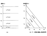
次に、図2乃至図4を参照して、本実施例のシステムにおける動作について説明する。図2は、車両の現在位置を測位するうえでの精度誤差と走行位置との関係を表した図を示す。図3は、本実施例の支援制御装置10に用いられる測位の精度誤差とその精度誤差レベルとの関係を表した図を示す。また、図4は、本実施例の支援制御装置10において支援制御部14が実行する制御ルーチンの一例のフローチャートを示す。
Next, the operation of the system according to the present embodiment will be described with reference to FIGS. FIG. 2 is a diagram showing the relationship between the accuracy error in measuring the current position of the vehicle and the travel position. FIG. 3 is a diagram showing the relationship between the positioning accuracy error used in the
本実施例の支援制御装置10において、測位部12の推測航法部24は、所定時間ごとに、各受信機やセンサ16〜22の出力信号に基づいて、自車両位置の初期座標からの走行軌跡を作成して、マップマッチング部26に供給する。マップマッチング部26は、推測航法部24からの推測軌跡情報を受信するごとに、推測航法部24により作成された自車両位置の初期座標からの走行軌跡を、地図データベース30に地図データとして格納されている道路のリンク情報と照らし合わせることにより、自車両の現在位置をその道路リンク上に補正するマップマッチングを行う。
In the
マップマッチング部26は、マップマッチングの結果に基づいて、そのマップマッチングの結果である現在位置から自車両が今後所定時間内又は所定距離内に走行すると推測される道路範囲(複数レーンのときはすべてのレーン)の地図データを地図データベース30から読み出す処理を行う。そして、その所定道路範囲においてバックカメラ32により認識すべき地物が存在するか否かを判別して、バックカメラ32による車両後方画像の認識を行うべきか否かを判別する。尚、現在位置から所定道路範囲において認識すべき地物が存在するか否かにより、認識すべき地物の存在位置よりも手前からバックカメラ32による画像認識を要求すべきか否かを判別するのは、マップマッチングの結果として検出された自車両の現在位置が正確でない可能性があるからである。
Based on the map matching result, the
マップマッチング部26は、上記の判別の結果、所定道路範囲に認識すべき地物が存在しないときは、何ら処理を行わない。一方、所定道路範囲に認識すべき地物が存在するときは、バックカメラ32からの撮像画像についてエッジ抽出などの画像処理を行って、画像処理の結果に基づいてカメラ撮像画像から認識すべき地物を抽出すると共に、その地物の自車両に対する相対位置関係を検出する。そして、かかる検出を行った場合には、地図データベース30にアクセスしてその認識地物の位置データを読み出すと共に、その位置データと検出された自車両と認識地物との相対位置関係とに基づいて、自車両の位置を検出する。この場合、自車両の位置は、カメラ撮像画像から認識された認識地物に従った位置へマップマッチングされる。
As a result of the above determination, the
マップマッチング部26は、所定道路範囲に認識すべき地物が存在するときは、また、バックカメラ32による画像処理の結果に基づいてカメラ撮像画像から自車両の走行する自レーンを抽出すると共に、その自レーンの自車両に対する相対位置関係を検出する。この際には、更に、地図データベース30にアクセスして自車位置近傍における走行レーンのレーン幅やレーン数,形状等を取得して、そして、自車両が現時点で走行する道路上の自レーンの位置を算出する。
When there is a feature to be recognized in the predetermined road range, the
マップマッチング部26は、自車両の位置を測位すると共に道路上の自レーン位置を算出すると、自車両の進行方向前方の自レーン上に支援制御を実行するのに必要な目標地物が存在するか否かを判別する。その判別の結果、目標地物が存在するときは、まず、地図データベース30からその目標地物の位置データを読み出し、その後は、検出自車位置とその目標地物の位置との関係に基づいて自車両からその目標地物までの道なり残距離を算出する。そして、その道なり残距離の情報を時刻の情報を付して現在地管理部36へ供給出力する。また、マップマッチング部26は、自車両の位置を測位するごとに、その時点での測位される自車両の現在位置の精度誤差を算出する。そして、測位した自車両の現在位置の情報をその精度誤差の情報と共に、時刻の情報を付して現在地管理部36へ供給出力する。
When the
現在地管理部36は、マップマッチング部26で算出された自車両の現在位置や道なり残距離を検知して、自車両の現在地座標や目標地物との距離や時間等の情報を支援制御部14のECU40へ送信すると共に、マップマッチング部26からの位置精度誤差(すなわちマップマッチングの実行履歴)の情報と地図データベース30からの地図データの更新履歴の情報とに基づいて、総合的な自車両の現在位置の測位精度誤差を算出して、その精度誤差を誤差レベル判定部38へ送信する。尚、現在地管理部36は、マップマッチングの実行履歴に基づく測位精度誤差と、地図データベース30の更新履歴に基づく測位結果の精度誤差と、を別個に算出して、誤差レベル判定部38へ送信することとしてもよい。
The current
ところで、本実施例において車両の現在位置を測位するうえでは、GPS受信機16や方位センサ18,Gセンサ20,車速センサ22,バックカメラ32を用いる。この場合には、受信機16やセンサ18〜22,カメラ32における検出パラメータの誤差や測位時の各種計算に含まれる誤差(例えばタイミングの丸め込み誤差)などが発生するため、車両位置の測位結果に誤差が生ずる。この測位誤差は、車両の移動に伴って積算される。一方、本実施例において、測位部12は、バックカメラ32の撮像画像から認識すべき地物を認識して自車両の位置を補正するマップマッチングを行うが、このマップマッチングが行われると、その測位される自車両の現在位置の位置精度は最も良くなり、その誤差は最も小さなものとなる。従って、測位誤差は、カメラ撮像画像からの地物認識に基づくマップマッチング後の車両の移動距離が長くなるほど大きくなる(図2参照)。
By the way, in the present embodiment, the
また、本実施例においては、地図データベース30に格納される更新可能な地図データを用いて自車位置が測位されるが、地図データベース30の更新からの経過時間が長くなると、道路の改修や新設などによりその地図データベース30に格納される地図データが現実のものと異なることがあるため、その地図データベース30の更新条件・更新頻度或いは前回更新からの経過時間・移動距離に応じて自車位置の測位誤差が変動する可能性がある。具体的には、地図データベース30の更新後の経過時間や移動距離が長いほど、また、その更新条件等が更新され難いものであるほど測位誤差が大きくなる。
In this embodiment, the position of the vehicle is measured using the updatable map data stored in the
現在地管理部36は、マップマッチング部26から供給されたカメラ撮像画像からの地物認識に基づくマップマッチング後の車両の移動距離と、地図データベース30から供給されたその地図データの更新条件・更新頻度或いは前回更新からの経過時間・移動距離とに基づいて、自車両の現在位置の測位精度誤差を算出して、誤差レベル判別部38へ送信する。
The current
誤差レベル判定部38は、現在地管理部36からの自車位置の測位精度誤差に基づいて、図3に示す如きマップを参照して、その測位を行ううえでの精度誤差レベルを特定する。具体的には、現在地管理部36が総合的な自車位置の測位精度誤差を算出するシステムでは、図3(A)に示す如き一次元的なマップが誤差レベル判定部38に格納されており、このときは、かかる一次元マップを参照して精度誤差レベルが特定される。一方、現在地管理部36がマップマッチングの実行履歴に基づく測位精度誤差と、地図データベース30の更新履歴に基づく測位精度誤差と、を別個に算出するシステムでは、図3(B)に示す如き二次元的なマップが誤差レベル判定部38に格納されており、このときは、かかる二次元マップを参照して精度誤差レベルが特定される。
Based on the positioning accuracy error of the vehicle position from the current
誤差レベル判定部38は、自車両の位置測位の精度誤差レベルを特定すると、そのレベル情報を支援制御部14に送信する。支援制御部14は、誤差レベル判定部38から送信される測位の精度誤差レベルの情報を受信し(ステップ150)、そして、その精度誤差レベルに基づいて、パターン記憶部52に格納されている複数の出力/実行パターンからその精度誤差レベルに対応して実行可能な制御レベルを選択する(ステップ152)。
When the error
例えば、特定された測位の精度誤差レベルが最も小さいレベル1であるときは、目標地物(一時停止線や交差点など)に対する自車両の位置が最も高精度に検出されるので、その目標地物の位置に対して比較的忠実に車両運転の支援を行う回避制御パターンを選択し、一方、その精度誤差レベルが最も小さいレベル4であるときは、目標地物に対する自車両の位置があまり高精度に検出されないので、その目標地物の位置に対して比較的曖昧に車両運転の支援を行う存在情報提供パターンを選択する。 For example, when the specified positioning accuracy error level is the smallest level 1, the position of the vehicle with respect to the target feature (such as a temporary stop line or an intersection) is detected with the highest accuracy. When the avoidance control pattern for assisting driving of the vehicle is selected relatively faithfully with respect to the position of the vehicle, while the accuracy error level is the smallest level 4, the position of the host vehicle with respect to the target feature is very accurate. Therefore, the presence information provision pattern for assisting the driving of the vehicle is selected relatively vaguely with respect to the position of the target feature.
支援制御部14のECU40は、上記の如く選択された制御レベルに従って支援制御を行う。この際、ECU40は、測位部12から供給される自車両の現在位置及び一時停止線や交差点などの制御対象である目標地物までの距離や時間(ステップ154)に基づいて、選択された制御レベルの支援形態に定められている制御開始条件が成立するか否かを判別し(ステップ156)、その開始条件が成立する場合にはその制御レベルに従った支援制御を開始する(ステップ158)。
The ECU 40 of the
例えば、測位精度が高くてその誤差が小さいことで回避制御パターンが選択されたときは、測位される自車両から目標地物としての一時停止線までの距離が30メートルになった時点でブレーキアクチュエータ42による自動ブレーキを開始して、車両をその一時停止線で停車させる。尚、この際、ブレーキアクチュエータ42による自動的な制動ブレーキを開始する前に、運転者に対してその自動的な制動ブレーキが行われることを知らせる音声案内などを行うこととしてもよい。また一方、測位精度が低くてその誤差が大きいことで存在情報提供パターンが選択されたときは、測位される自車両から目標地物としての一時停止線までの距離が100メートルになった時点でブザー警報器50によるブザー吹鳴や警報出力,スピーカ出力を開始して、運転者に前方に一時停止線が存在することを知らせる注意喚起を行う。
For example, when the avoidance control pattern is selected because the positioning accuracy is high and the error is small, when the distance from the vehicle to be measured to the temporary stop line as the target feature becomes 30 meters, the brake actuator The automatic braking by 42 is started and the vehicle is stopped at the temporary stop line. At this time, before starting the automatic braking brake by the
このように、本実施例の支援制御装置10においては、カメラ撮像画像からの地物認識に基づくマップマッチングの実行頻度やその前回実行からの移動距離ならびに地図データベース30の更新条件・更新頻度やその前回更新からの経過時間・移動距離に基づいて、車両走行時に様々な要因で経時変化する測位の精度誤差が算出されると共に、その精度誤差に対して支援制御を実行するうえで最適な精度誤差レベルが複数のものから特定される。そして、その精度誤差レベルに従った支援形態について支援制御の実行が許容される。この点、本実施例においては、車両走行時に算出される測位の精度誤差の大きさ(具体的には、その精度誤差レベル)に応じて、測位される自車両の位置に応じて実行される支援制御(上記した一時停止制御や速度制御などの各制御)の制御レベルが変更される。
As described above, in the
測位の精度が低くその誤差が大きいときは、測位される自車両の位置が正確でないときがあるため、支援制御のうちでも自車両の測位位置に対する忠実な制御が要求される支援形態(例えば回避制御パターンなど)を実行することは適切でない一方、その測位位置に対するあまり厳格な制御が要求されない支援形態(例えば存在情報提供パターンなど)を実行することに支障はほとんどない。逆に、測位の精度が高くその誤差が小さいときは、測位される自車両の位置が正確な位置から大きくずれていることは皆無であるため、自車両の測位位置に対する忠実な制御が要求される支援形態を実行することは可能である。 When the positioning accuracy is low and the error is large, the position of the host vehicle to be positioned may not be accurate. Therefore, among the support controls, a support mode that requires faithful control over the positioning position of the host vehicle (for example, avoidance) It is not appropriate to execute a control pattern, etc.), but there is almost no trouble in executing a support form (for example, a presence information providing pattern) that does not require very strict control over the positioning position. On the other hand, when the positioning accuracy is high and the error is small, the position of the own vehicle to be positioned is not greatly deviated from the accurate position, so faithful control over the positioning position of the own vehicle is required. It is possible to execute the support form.
本実施例においては、測位の精度誤差レベルが誤差の最も小さいレベル1であるときは、測位位置に対する忠実な制御が要求されるレベル1の制御レベルで、また、その精度誤差レベルが次に誤差の小さいレベル2であるときは、その次に測位位置に対する忠実な制御が要求されるレベル2の制御レベルで、また、その精度誤差レベルが次に誤差の小さいレベル3であるときは、その次に測位位置に対する忠実な制御が要求されるレベル3の制御レベルで、更に、その精度誤差レベルが誤差の最も大きいレベル4であるときは、最も測位位置に対する忠実な制御が要求されないレベル4の制御レベルで、支援制御が実行される。 In this embodiment, when the positioning accuracy error level is level 1 with the smallest error, it is the level 1 control level that requires faithful control over the positioning position, and the accuracy error level is the next error. When the level 2 is small, the level 2 is the next control level that requires the faithful control over the positioning position. When the accuracy error level is the level 3 with the next smallest error, the level 2 is the next level. Further, when the level 3 control level is required to faithfully control the positioning position, and the accuracy error level is the level 4 with the largest error, the level 4 control where the most faithful control over the positioning position is not required. At the level, support control is executed.
すなわち、一時停止制御などの自車両の位置に応じて実行される支援制御を、複数の段階的な制御レベルのうちその実行時点での自車両の位置を測位するうえでの精度誤差に対応した制御レベルで実行させることが可能である。この点において、本実施例の支援制御装置10によれば、上記の支援制御を自車両の位置測位の精度誤差に対応して適切に実行させることが可能となっている。
That is, support control executed according to the position of the host vehicle, such as temporary stop control, corresponds to an accuracy error in positioning the position of the host vehicle at the time of execution among a plurality of stepwise control levels. It can be executed at the control level. In this respect, according to the
また、測位の精度が高くその誤差が小さいときは、測位される自車両の位置が正確な位置から大きくずれていることは皆無であるため、支援制御の開始タイミングが遅くても、その開始タイミングの時点で既に自車両が目標地物の地点を通過しているなどの不測の事態が生ずることはない。一方、測位の精度が低くその誤差が大きいときは、測位される自車両の位置が正確な位置から大きくずれていることがあるため、支援制御の開始タイミングが遅いと、上記した不測の事態が生ずるおそれがある。 In addition, when the positioning accuracy is high and the error is small, the position of the host vehicle to be positioned is not greatly deviated from the accurate position. At such time, there will be no unexpected situation such as the vehicle already passing the target feature point. On the other hand, when the positioning accuracy is low and the error is large, the position of the host vehicle to be positioned may be greatly deviated from the accurate position. May occur.
これに対して、本実施例の支援制御装置10において、支援制御の各支援形態の実行開始タイミングは、支援形態ごとに異なっており、対応する誤差が大きいものの順に自車両が目標地物に接近する状況においてより早いものとなる。すなわち、支援制御が開始されるタイミングは、測位の精度誤差が大きいときほど早くなり、測位の精度誤差が小さいときほど遅くなる。従って、本実施例の支援制御装置10によれば、仮に測位される自車両の位置が実際の正確な位置から大きくかけ離れているときにも、大きな精度誤差が生じているおそれのある対象物位置に応じて実行される支援制御によって不測の事態が生ずるのを防止することが可能となっている。
On the other hand, in the
尚、上記の実施例においては、測位部12が、カメラ撮像画像からの地物認識に基づくマップマッチングの実行履歴情報および地図データベース30の更新履歴情報に基づいて自車両の現在位置の測位精度誤差を算出することにより特許請求の範囲に記載した「精度誤差算出手段」が、支援制御部14のECU40が、支援制御の制御レベルを上記の如く算出した精度誤差に応じた精度誤差レベルに応じて変更することにより特許請求の範囲に記載した「制御レベル変更手段」が、それぞれ実現されている。
In the above embodiment, the
ところで、上記の実施例においては、測位部12におけるマップマッチングの実行履歴の情報と地図データベース30の更新履歴の情報とに基づいて現時点における総合的な自車両の位置の測位精度誤差を算出したうえで、支援制御の制御レベルをその算出時点での測位精度誤差に応じて変更することとしている。上記の如く、測位精度誤差は、前回のマップマッチングや地図データの更新からの車両の移動距離に応じて直線状に変動するものである。そこで、自車両から目標地物までの道なり残距離が測定された後に、その測定距離と現時点での精度誤差とに基づいて、自車両がその目標地物に到達した際に生じると予測される測位の精度誤差を算出したうえで、その算出した精度誤差に応じて支援制御の制御レベルを変更し、自車両がその目標地物に到達する前に支援制御を実行させることとしてもよい。かかる構成においても、複数の段階的な制御レベルからなる支援制御を自車位置の測位精度誤差に対応して適切に実行させることが可能となる。
By the way, in the above embodiment, after calculating the overall positioning accuracy error of the position of the host vehicle based on the information on the execution history of map matching in the
また、上記の実施例においては、車両の後部に配設されたバックカメラ32を用いて地物や走行レーンの認識を行うこととしているが、車両の前部に配設されたフロントカメラを用いてそれらの認識を行うこととしてもよいし、また、外部インフラから送られてくる情報に基づいて地物などの認識を行うこととしてもよい。
Further, in the above-described embodiment, the feature or travel lane is recognized using the
また、上記の実施例においては、地図データベース30を車両に搭載するものとしたが、センタに設けるシステムとし、車両がその都度通信アクセスしてその地図データベースに格納するデータを読み出せるようにしてもよい。
In the above embodiment, the
また、上記の実施例においては、まず測位の精度誤差に応じてその精度誤差レベルを特定したうえで、その精度誤差レベルに応じて支援制御の制御レベルを変更することとしたが、本発明はこれに限定されるものではなく、測位の精度誤差自体に応じて支援制御の制御レベルを線形的に変更することとしてもよい。例えば、上記した案内制御においては、その音声による経路案内について、測位の精度誤差が小さいほどその開始タイミングを線形的に遅くする。 In the above embodiment, first, the accuracy error level is specified according to the positioning accuracy error, and then the control level of the assist control is changed according to the accuracy error level. However, the present invention is not limited to this, and the control level of the assist control may be linearly changed according to the positioning accuracy error itself. For example, in the above-described guidance control, the start timing of the route guidance by voice is linearly delayed as the positioning accuracy error is smaller.
更に、上記の実施例においては、支援制御として一時停止制御、交差点制御、速度制御、案内制御を挙げたが、自車両の位置に応じて実行される他の制御を行うシステムに適用することとしてもよい。 Furthermore, in the above embodiment, the suspension control, the intersection control, the speed control, and the guidance control are cited as the assist control. However, the present invention is applied to a system that performs other control executed according to the position of the host vehicle. Also good.
10 支援制御装置
12 測位部
14 支援制御部
30 地図データベース
36 現在地管理部
38 誤差レベル判定部
40 ECU
52 パターン記憶部
DESCRIPTION OF
52 Pattern storage
Claims (4)
対象物位置に応じて実行される支援制御の制御レベルを、前記精度誤差算出手段により算出される前記精度誤差に応じて変更する制御レベル変更手段と、
を備え、
前記制御レベル変更手段は、前記精度誤差算出手段により算出される前記精度誤差が大きいほど、前記支援制御の実行開始タイミングを早めることを特徴とする支援制御装置。 An accuracy error calculating means for calculating an accuracy error in positioning the object position based on the update history of the map database storing the map data;
Control level changing means for changing the control level of the assist control executed according to the object position according to the accuracy error calculated by the accuracy error calculating means;
With
The support control device, wherein the control level changing means increases the execution start timing of the support control as the precision error calculated by the precision error calculating means increases.
Priority Applications (6)
| Application Number | Priority Date | Filing Date | Title |
|---|---|---|---|
| JP2006135792A JP5162103B2 (en) | 2006-05-15 | 2006-05-15 | Support control device |
| EP07743412A EP2019382B1 (en) | 2006-05-15 | 2007-05-15 | Support control device |
| CN2007800176543A CN101443831B (en) | 2006-05-15 | 2007-05-15 | Support control device |
| KR1020087027580A KR100967329B1 (en) | 2006-05-15 | 2007-05-15 | Support control device |
| US12/300,737 US8271174B2 (en) | 2006-05-15 | 2007-05-15 | Support control device |
| PCT/JP2007/059977 WO2007132858A1 (en) | 2006-05-15 | 2007-05-15 | Support control device |
Applications Claiming Priority (1)
| Application Number | Priority Date | Filing Date | Title |
|---|---|---|---|
| JP2006135792A JP5162103B2 (en) | 2006-05-15 | 2006-05-15 | Support control device |
Publications (2)
| Publication Number | Publication Date |
|---|---|
| JP2007305079A JP2007305079A (en) | 2007-11-22 |
| JP5162103B2 true JP5162103B2 (en) | 2013-03-13 |
Family
ID=38693947
Family Applications (1)
| Application Number | Title | Priority Date | Filing Date |
|---|---|---|---|
| JP2006135792A Active JP5162103B2 (en) | 2006-05-15 | 2006-05-15 | Support control device |
Country Status (6)
| Country | Link |
|---|---|
| US (1) | US8271174B2 (en) |
| EP (1) | EP2019382B1 (en) |
| JP (1) | JP5162103B2 (en) |
| KR (1) | KR100967329B1 (en) |
| CN (1) | CN101443831B (en) |
| WO (1) | WO2007132858A1 (en) |
Families Citing this family (49)
| Publication number | Priority date | Publication date | Assignee | Title |
|---|---|---|---|---|
| JP4366664B2 (en) * | 2007-06-29 | 2009-11-18 | アイシン・エィ・ダブリュ株式会社 | Own vehicle position recognition device and own vehicle position recognition program |
| DE102008012697A1 (en) * | 2007-12-12 | 2009-06-18 | Daimler Ag | Method for operating a navigation system and navigation system |
| CN102171084B (en) * | 2008-09-30 | 2013-12-04 | 日产自动车株式会社 | System provided with an assistance-controller for assisting an operator of the system, control-operation assisting device, control-operation assisting method, driving-operation assisting device, and driving-operation assisting method |
| JP5387277B2 (en) * | 2009-08-07 | 2014-01-15 | アイシン・エィ・ダブリュ株式会社 | Information reliability identification device, method and program used in driving support |
| JP5504743B2 (en) * | 2009-08-07 | 2014-05-28 | アイシン・エィ・ダブリュ株式会社 | Driving support content determination device, driving support content determination method, and driving support content determination program |
| US9234760B2 (en) * | 2010-01-29 | 2016-01-12 | Blackberry Limited | Portable mobile transceiver for GPS navigation and vehicle data input for dead reckoning mode |
| DE102010008816A1 (en) * | 2010-02-22 | 2011-08-25 | Continental Automotive GmbH, 30165 | Method for online communication |
| JP5626578B2 (en) | 2010-12-02 | 2014-11-19 | アイシン・エィ・ダブリュ株式会社 | Driving support system, driving support program, and driving support method |
| EP2650857B1 (en) * | 2010-12-08 | 2020-01-22 | Toyota Jidosha Kabushiki Kaisha | Driving assistance device |
| JP5706698B2 (en) * | 2011-01-20 | 2015-04-22 | 本田技研工業株式会社 | Auto reducer for automobile |
| EP2765047B1 (en) * | 2011-10-03 | 2019-12-04 | Toyota Jidosha Kabushiki Kaisha | Driving assistance system for vehicle |
| JP5773206B2 (en) | 2011-12-13 | 2015-09-02 | アイシン・エィ・ダブリュ株式会社 | Elevation reliability determination system, data maintenance system, travel support system, travel support program and method, data maintenance program and method, and elevation reliability determination program and method |
| KR101919366B1 (en) * | 2011-12-22 | 2019-02-11 | 한국전자통신연구원 | Apparatus and method for recognizing vehicle location using in-vehicle network and image sensor |
| DE102012023561B4 (en) * | 2012-12-03 | 2014-08-14 | Audi Ag | Method for traffic-related adaptation of stopping processes to a synthetically modulated speed profile along a vehicle-driven route and control device for carrying out the method |
| DE102013104256A1 (en) * | 2013-04-26 | 2014-10-30 | Conti Temic Microelectronic Gmbh | Method and device for estimating the number of lanes |
| DE102013016435B4 (en) * | 2013-10-02 | 2015-12-24 | Audi Ag | Method for correcting position data and motor vehicle |
| CN106461403B (en) * | 2014-05-20 | 2019-02-15 | 日产自动车株式会社 | Article detection device and object detecting method |
| JP2016048226A (en) * | 2014-08-28 | 2016-04-07 | パイオニア株式会社 | Information processing apparatus, information processing method, and program for information processing and recording medium |
| JP6353322B2 (en) * | 2014-09-04 | 2018-07-04 | 日立建機株式会社 | Transport vehicle and travel control device thereof |
| JP6298772B2 (en) * | 2015-01-14 | 2018-03-20 | 日立オートモティブシステムズ株式会社 | In-vehicle control device, own vehicle position and orientation identification device, in-vehicle display device |
| WO2016151750A1 (en) * | 2015-03-24 | 2016-09-29 | パイオニア株式会社 | Map information storage device, automatic drive control device, control method, program, and storage medium |
| KR101946748B1 (en) * | 2015-04-13 | 2019-02-11 | 닛산 지도우샤 가부시키가이샤 | Apparatus and method for verifying vehicle periphery information |
| KR101991611B1 (en) * | 2015-05-26 | 2019-06-20 | 닛산 지도우샤 가부시키가이샤 | Apparatus and method for setting stop position |
| CN104943689B (en) * | 2015-06-03 | 2017-05-10 | 奇瑞汽车股份有限公司 | Control method for active automobile anti-collision system |
| RU2690727C1 (en) * | 2015-07-27 | 2019-06-05 | Ниссан Мотор Ко., Лтд. | Device for controlling movement along route and method of controlling movement along route |
| DE102015215699A1 (en) * | 2015-08-18 | 2017-02-23 | Robert Bosch Gmbh | Method for locating an automated motor vehicle |
| JP6795379B2 (en) * | 2016-03-10 | 2020-12-02 | パナソニック インテレクチュアル プロパティ コーポレーション オブ アメリカPanasonic Intellectual Property Corporation of America | Operation control device, operation control method and operation control program |
| JP6630443B2 (en) * | 2016-10-03 | 2020-01-15 | 本田技研工業株式会社 | Vehicle control device |
| KR102420597B1 (en) * | 2016-11-17 | 2022-07-13 | 현대모비스 주식회사 | Autonomous driving system fail-safe utility and method thereof |
| CN106908055A (en) * | 2017-03-17 | 2017-06-30 | 安科智慧城市技术(中国)有限公司 | A kind of multi-modal air navigation aid and mobile robot |
| WO2018179616A1 (en) * | 2017-03-27 | 2018-10-04 | 三菱電機株式会社 | Vehicle position deduction apparatus |
| US11008039B2 (en) * | 2017-04-12 | 2021-05-18 | Toyota Jidosha Kabushiki Kaisha | Lane change assist apparatus for vehicle |
| DE102017004118A1 (en) * | 2017-04-27 | 2018-10-31 | Daimler Ag | Method for operating a driver assistance system |
| WO2018216058A1 (en) * | 2017-05-22 | 2018-11-29 | 三菱電機株式会社 | Position estimation device, position estimation method, and position estimation program |
| US10551509B2 (en) * | 2017-06-30 | 2020-02-04 | GM Global Technology Operations LLC | Methods and systems for vehicle localization |
| CN109211236B (en) * | 2017-06-30 | 2022-03-04 | 沈阳新松机器人自动化股份有限公司 | Navigation positioning method and device and robot |
| DE102017211629A1 (en) * | 2017-07-07 | 2019-01-10 | Robert Bosch Gmbh | Method for operating a higher automated vehicle (HAF), in particular a highly automated vehicle |
| EP3678109B1 (en) | 2017-08-30 | 2023-05-03 | Nissan Motor Co., Ltd. | Position correction method for driving-assist vehicle and position error correction device |
| JP7127289B2 (en) * | 2018-02-08 | 2022-08-30 | 株式会社デンソー | Driving support device, program, driving support method |
| US11727794B2 (en) | 2018-03-14 | 2023-08-15 | Micron Technology, Inc. | Systems and methods for evaluating and sharing human driving style information with proximate vehicles |
| US10997429B2 (en) * | 2018-04-11 | 2021-05-04 | Micron Technology, Inc. | Determining autonomous vehicle status based on mapping of crowdsourced object data |
| KR102420568B1 (en) * | 2018-04-27 | 2022-07-13 | 삼성전자주식회사 | Method for determining a position of a vehicle and vehicle thereof |
| KR102420476B1 (en) * | 2018-05-25 | 2022-07-13 | 에스케이텔레콤 주식회사 | Apparatus and method for estimating location of vehicle and computer recordable medium storing computer program thereof |
| US11161518B2 (en) | 2018-06-15 | 2021-11-02 | Micron Technology, Inc. | Detecting road conditions based on braking event data received from vehicles |
| JP7189691B2 (en) * | 2018-07-02 | 2022-12-14 | 株式会社Subaru | Vehicle cruise control system |
| JP7119720B2 (en) * | 2018-07-30 | 2022-08-17 | 株式会社デンソー | Driving support device |
| JP7151566B2 (en) * | 2019-03-14 | 2022-10-12 | トヨタ自動車株式会社 | Vehicle running control device |
| JP7245084B2 (en) * | 2019-03-15 | 2023-03-23 | 日立Astemo株式会社 | Autonomous driving system |
| JP7247829B2 (en) * | 2019-09-18 | 2023-03-29 | トヨタ自動車株式会社 | hybrid car |
Family Cites Families (19)
| Publication number | Priority date | Publication date | Assignee | Title |
|---|---|---|---|---|
| JPS5474700A (en) * | 1977-11-26 | 1979-06-14 | Agency Of Ind Science & Technol | Collection and delivery system for traffic information by photo electric conversion element group |
| US4433325A (en) * | 1980-09-30 | 1984-02-21 | Omron Tateisi Electronics, Co. | Optical vehicle detection system |
| US5166681A (en) * | 1990-07-30 | 1992-11-24 | Bottesch H Werner | Passive vehicle presence detection system |
| JP3155394B2 (en) | 1993-06-01 | 2001-04-09 | アルパイン株式会社 | Car navigation system |
| US6199001B1 (en) * | 1996-12-19 | 2001-03-06 | Toyota Jidosha Kabushiki Kaisha | Control system for controlling the behavior of a vehicle based on accurately detected route information |
| JP3388132B2 (en) * | 1997-04-09 | 2003-03-17 | 本田技研工業株式会社 | Vehicle control device |
| JP3517364B2 (en) * | 1998-11-27 | 2004-04-12 | 富士通テン株式会社 | Navigation system |
| JP3167990B2 (en) | 1999-09-14 | 2001-05-21 | 富士重工業株式会社 | Curve approach control device |
| US6907347B2 (en) * | 2002-11-21 | 2005-06-14 | Ford Global Technologies, Llc | Systems and method for estimating speed and pitch sensor errors |
| JP4055653B2 (en) | 2003-05-27 | 2008-03-05 | 株式会社デンソー | Vehicle speed control device and program |
| JP2005077211A (en) | 2003-08-29 | 2005-03-24 | Matsushita Electric Ind Co Ltd | Navigation system |
| JP4225184B2 (en) * | 2003-11-11 | 2009-02-18 | 日産自動車株式会社 | Map reliability calculation device |
| JP4552750B2 (en) * | 2004-08-06 | 2010-09-29 | 株式会社デンソー | Vehicle headlamp device |
| CN100535598C (en) * | 2004-08-20 | 2009-09-02 | 爱信精机株式会社 | Parking auxiliary device for vehicle and parking auxiliary method |
| JP4371982B2 (en) | 2004-11-08 | 2009-11-25 | キヤノン株式会社 | Image processing apparatus, control method therefor, computer program, and computer-readable storage medium |
| JP4696720B2 (en) * | 2005-06-24 | 2011-06-08 | 日産自動車株式会社 | Automatic steering control device |
| WO2007040069A1 (en) | 2005-09-30 | 2007-04-12 | Pioneer Corporation | Error calculation device and navigation device |
| JP4415949B2 (en) | 2006-01-25 | 2010-02-17 | 株式会社日立製作所 | Travel control system and travel control method |
| JP2009530669A (en) * | 2006-03-16 | 2009-08-27 | ブルベーカー,カーチス,エム. | System and method for generating revenue by displaying highly relevant advertisements on moving objects |
-
2006
- 2006-05-15 JP JP2006135792A patent/JP5162103B2/en active Active
-
2007
- 2007-05-15 EP EP07743412A patent/EP2019382B1/en not_active Not-in-force
- 2007-05-15 WO PCT/JP2007/059977 patent/WO2007132858A1/en active Search and Examination
- 2007-05-15 US US12/300,737 patent/US8271174B2/en active Active
- 2007-05-15 CN CN2007800176543A patent/CN101443831B/en not_active Expired - Fee Related
- 2007-05-15 KR KR1020087027580A patent/KR100967329B1/en not_active IP Right Cessation
Also Published As
| Publication number | Publication date |
|---|---|
| CN101443831B (en) | 2011-04-13 |
| WO2007132858A1 (en) | 2007-11-22 |
| KR100967329B1 (en) | 2010-07-05 |
| EP2019382B1 (en) | 2011-12-28 |
| CN101443831A (en) | 2009-05-27 |
| EP2019382A4 (en) | 2010-12-22 |
| JP2007305079A (en) | 2007-11-22 |
| KR20090007417A (en) | 2009-01-16 |
| US20090265070A1 (en) | 2009-10-22 |
| EP2019382A1 (en) | 2009-01-28 |
| US8271174B2 (en) | 2012-09-18 |
Similar Documents
| Publication | Publication Date | Title |
|---|---|---|
| JP5162103B2 (en) | Support control device | |
| JP4938351B2 (en) | Positioning information update device for vehicles | |
| JP4724043B2 (en) | Object recognition device | |
| JP4680131B2 (en) | Own vehicle position measuring device | |
| JP6361567B2 (en) | Automated driving vehicle system | |
| JP6705414B2 (en) | Operating range determination device | |
| CN109426261B (en) | Automatic driving device | |
| JP2007309670A (en) | Vehicle position detector | |
| CN107107751B (en) | Target vehicle speed generation device and travel control device | |
| JP4977218B2 (en) | Self-vehicle position measurement device | |
| US10053087B2 (en) | Driving assistance apparatus | |
| JP4896639B2 (en) | Driver driving characteristic learning device and vehicle driving safety device | |
| JP6941178B2 (en) | Automatic operation control device and method | |
| WO2016194168A1 (en) | Travel control device and method | |
| JP4724079B2 (en) | Object recognition device | |
| JP6943127B2 (en) | Position correction method, vehicle control method and position correction device | |
| JP2005138623A (en) | Vehicle travel supporting device | |
| JP7202982B2 (en) | Driving support method and driving support device | |
| JP2019144758A (en) | Automatic driving support device, automatic driving support system, automatic driving support method and program | |
| JP2023104764A (en) | Runway identifying device and runway identifying method | |
| JP2024039134A (en) | Vehicle control device and vehicle control method | |
| JP2023151311A (en) | Travel control method and travel control device | |
| JP2021115922A (en) | Travel support method and travel support apparatus | |
| JP2018177128A (en) | Path tracing control system |
Legal Events
| Date | Code | Title | Description |
|---|---|---|---|
| A621 | Written request for application examination |
Free format text: JAPANESE INTERMEDIATE CODE: A621 Effective date: 20090417 |
|
| A131 | Notification of reasons for refusal |
Free format text: JAPANESE INTERMEDIATE CODE: A131 Effective date: 20111108 |
|
| A521 | Written amendment |
Free format text: JAPANESE INTERMEDIATE CODE: A523 Effective date: 20120104 |
|
| A131 | Notification of reasons for refusal |
Free format text: JAPANESE INTERMEDIATE CODE: A131 Effective date: 20120508 |
|
| A521 | Written amendment |
Free format text: JAPANESE INTERMEDIATE CODE: A523 Effective date: 20120706 |
|
| A02 | Decision of refusal |
Free format text: JAPANESE INTERMEDIATE CODE: A02 Effective date: 20120731 |
|
| A521 | Written amendment |
Free format text: JAPANESE INTERMEDIATE CODE: A523 Effective date: 20121030 |
|
| A911 | Transfer of reconsideration by examiner before appeal (zenchi) |
Free format text: JAPANESE INTERMEDIATE CODE: A911 Effective date: 20121106 |
|
| TRDD | Decision of grant or rejection written | ||
| A01 | Written decision to grant a patent or to grant a registration (utility model) |
Free format text: JAPANESE INTERMEDIATE CODE: A01 Effective date: 20121127 |
|
| A61 | First payment of annual fees (during grant procedure) |
Free format text: JAPANESE INTERMEDIATE CODE: A61 Effective date: 20121217 |
|
| R151 | Written notification of patent or utility model registration |
Ref document number: 5162103 Country of ref document: JP Free format text: JAPANESE INTERMEDIATE CODE: R151 |
|
| FPAY | Renewal fee payment (event date is renewal date of database) |
Free format text: PAYMENT UNTIL: 20151221 Year of fee payment: 3 |
|
| R250 | Receipt of annual fees |
Free format text: JAPANESE INTERMEDIATE CODE: R250 |
|
| R250 | Receipt of annual fees |
Free format text: JAPANESE INTERMEDIATE CODE: R250 |
|
| R250 | Receipt of annual fees |
Free format text: JAPANESE INTERMEDIATE CODE: R250 |
|
| R250 | Receipt of annual fees |
Free format text: JAPANESE INTERMEDIATE CODE: R250 |
|
| R250 | Receipt of annual fees |
Free format text: JAPANESE INTERMEDIATE CODE: R250 |
|
| R250 | Receipt of annual fees |
Free format text: JAPANESE INTERMEDIATE CODE: R250 |