JP4371982B2 - Image processing apparatus, control method therefor, computer program, and computer-readable storage medium - Google Patents
Image processing apparatus, control method therefor, computer program, and computer-readable storage medium Download PDFInfo
- Publication number
- JP4371982B2 JP4371982B2 JP2004324076A JP2004324076A JP4371982B2 JP 4371982 B2 JP4371982 B2 JP 4371982B2 JP 2004324076 A JP2004324076 A JP 2004324076A JP 2004324076 A JP2004324076 A JP 2004324076A JP 4371982 B2 JP4371982 B2 JP 4371982B2
- Authority
- JP
- Japan
- Prior art keywords
- image
- data
- resolution
- decoding
- output
- Prior art date
- Legal status (The legal status is an assumption and is not a legal conclusion. Google has not performed a legal analysis and makes no representation as to the accuracy of the status listed.)
- Expired - Fee Related
Links
- 238000000034 method Methods 0.000 title claims description 51
- 238000004590 computer program Methods 0.000 title claims description 7
- 238000004891 communication Methods 0.000 claims description 9
- 230000006870 function Effects 0.000 claims description 4
- 230000008569 process Effects 0.000 description 35
- 238000006243 chemical reaction Methods 0.000 description 11
- 230000004044 response Effects 0.000 description 11
- 238000010586 diagram Methods 0.000 description 9
- 238000000354 decomposition reaction Methods 0.000 description 6
- 239000003550 marker Substances 0.000 description 4
- 101100264195 Caenorhabditis elegans app-1 gene Proteins 0.000 description 3
- 230000007246 mechanism Effects 0.000 description 3
- 230000005540 biological transmission Effects 0.000 description 2
- 238000005516 engineering process Methods 0.000 description 2
- 239000000284 extract Substances 0.000 description 2
- 239000008186 active pharmaceutical agent Substances 0.000 description 1
- 230000001174 ascending effect Effects 0.000 description 1
- 238000004364 calculation method Methods 0.000 description 1
- 230000008859 change Effects 0.000 description 1
- 230000006835 compression Effects 0.000 description 1
- 238000007906 compression Methods 0.000 description 1
- 230000000694 effects Effects 0.000 description 1
- 238000001914 filtration Methods 0.000 description 1
- 239000004973 liquid crystal related substance Substances 0.000 description 1
- 230000000750 progressive effect Effects 0.000 description 1
- 230000009467 reduction Effects 0.000 description 1
Images


Classifications
-
- H—ELECTRICITY
- H04—ELECTRIC COMMUNICATION TECHNIQUE
- H04N—PICTORIAL COMMUNICATION, e.g. TELEVISION
- H04N19/00—Methods or arrangements for coding, decoding, compressing or decompressing digital video signals
- H04N19/10—Methods or arrangements for coding, decoding, compressing or decompressing digital video signals using adaptive coding
- H04N19/169—Methods or arrangements for coding, decoding, compressing or decompressing digital video signals using adaptive coding characterised by the coding unit, i.e. the structural portion or semantic portion of the video signal being the object or the subject of the adaptive coding
- H04N19/188—Methods or arrangements for coding, decoding, compressing or decompressing digital video signals using adaptive coding characterised by the coding unit, i.e. the structural portion or semantic portion of the video signal being the object or the subject of the adaptive coding the unit being a video data packet, e.g. a network abstraction layer [NAL] unit
-
- H—ELECTRICITY
- H04—ELECTRIC COMMUNICATION TECHNIQUE
- H04N—PICTORIAL COMMUNICATION, e.g. TELEVISION
- H04N19/00—Methods or arrangements for coding, decoding, compressing or decompressing digital video signals
- H04N19/10—Methods or arrangements for coding, decoding, compressing or decompressing digital video signals using adaptive coding
- H04N19/134—Methods or arrangements for coding, decoding, compressing or decompressing digital video signals using adaptive coding characterised by the element, parameter or criterion affecting or controlling the adaptive coding
- H04N19/162—User input
-
- H—ELECTRICITY
- H04—ELECTRIC COMMUNICATION TECHNIQUE
- H04N—PICTORIAL COMMUNICATION, e.g. TELEVISION
- H04N19/00—Methods or arrangements for coding, decoding, compressing or decompressing digital video signals
- H04N19/10—Methods or arrangements for coding, decoding, compressing or decompressing digital video signals using adaptive coding
- H04N19/134—Methods or arrangements for coding, decoding, compressing or decompressing digital video signals using adaptive coding characterised by the element, parameter or criterion affecting or controlling the adaptive coding
- H04N19/164—Feedback from the receiver or from the transmission channel
-
- H—ELECTRICITY
- H04—ELECTRIC COMMUNICATION TECHNIQUE
- H04N—PICTORIAL COMMUNICATION, e.g. TELEVISION
- H04N19/00—Methods or arrangements for coding, decoding, compressing or decompressing digital video signals
- H04N19/40—Methods or arrangements for coding, decoding, compressing or decompressing digital video signals using video transcoding, i.e. partial or full decoding of a coded input stream followed by re-encoding of the decoded output stream
-
- H—ELECTRICITY
- H04—ELECTRIC COMMUNICATION TECHNIQUE
- H04N—PICTORIAL COMMUNICATION, e.g. TELEVISION
- H04N19/00—Methods or arrangements for coding, decoding, compressing or decompressing digital video signals
- H04N19/44—Decoders specially adapted therefor, e.g. video decoders which are asymmetric with respect to the encoder
-
- H—ELECTRICITY
- H04—ELECTRIC COMMUNICATION TECHNIQUE
- H04N—PICTORIAL COMMUNICATION, e.g. TELEVISION
- H04N19/00—Methods or arrangements for coding, decoding, compressing or decompressing digital video signals
- H04N19/60—Methods or arrangements for coding, decoding, compressing or decompressing digital video signals using transform coding
- H04N19/63—Methods or arrangements for coding, decoding, compressing or decompressing digital video signals using transform coding using sub-band based transform, e.g. wavelets
-
- H—ELECTRICITY
- H04—ELECTRIC COMMUNICATION TECHNIQUE
- H04N—PICTORIAL COMMUNICATION, e.g. TELEVISION
- H04N19/00—Methods or arrangements for coding, decoding, compressing or decompressing digital video signals
- H04N19/70—Methods or arrangements for coding, decoding, compressing or decompressing digital video signals characterised by syntax aspects related to video coding, e.g. related to compression standards
Landscapes
- Engineering & Computer Science (AREA)
- Multimedia (AREA)
- Signal Processing (AREA)
- Compression Of Band Width Or Redundancy In Fax (AREA)
- Compression Or Coding Systems Of Tv Signals (AREA)
- Two-Way Televisions, Distribution Of Moving Picture Or The Like (AREA)
- Image Processing (AREA)
- Editing Of Facsimile Originals (AREA)
Description
本発明は圧縮符号化された画像データを処理する技術に関するものである。 The present invention relates to a technique for processing compressed and encoded image data.
近年、コンピュータの表示装置として用いられているディスプレイも技術の進化と共に、解像度が向上している。例えば従来であれば、VGA(640x480画素)、SVGA(800x600画素)程度であった解像度が、現在ではノートPCでさえ、XGA(1024x768画素)以上になり、ディスクトップPCにいたっては、SXGA(1280x1024画素), UXGA(1600x1200画素)が普及しており、更に今後はQXGA, QUXGAなどの高解像度をサポートすることは容易に推察できる。 In recent years, the resolution of a display used as a computer display device has improved with the evolution of technology. For example, in the past, the resolution of VGA (640x480 pixels) and SVGA (800x600 pixels) is now XGA (1024x768 pixels) or higher even for notebook PCs, and for desktop PCs, SXGA ( 1280x1024 pixels) and UXGA (1600x1200 pixels) are prevalent, and it can be easily guessed that high resolution such as QXGA and QUXGA will be supported in the future.
更に、デジタルカメラなどで撮影した多数の画像データを同時に表示し、その中から選択的に1枚表示に切り替えて、ズームやスクロールなどの表示技術により、より詳細な画像データを表示するようなアプリケーションがある。この場合、同時に多数の画像データを一度に表示する場合には、高速性が重要視されるため、主画像データとは異なる予め作成されているサムネイル画像データを用いることが多い。一方そのサムネイル表示から選択された画像データの一枚表示は、主画像データを用いて、アプリケーションのウィンドウサイズあるいは、ディスプレイ装置に表示できるまでは、画像全体を表示し、それ以上の拡大表示になると、画像の一部分を表示する。 In addition, an application that simultaneously displays a large number of image data taken with a digital camera, etc., selectively switches to one image display, and displays more detailed image data using display technologies such as zoom and scroll. There is. In this case, when a large number of image data is displayed at the same time, high speed is regarded as important. Therefore, thumbnail image data created in advance different from the main image data is often used. On the other hand, the single image display selected from the thumbnail display uses the main image data to display the entire image until it can be displayed on the window size of the application or on the display device. Display a part of the image.
このような、1枚の画像データを表示する際に、元々の画像データの画像サイズとは異なる元々の画像データの画像サイズより小さい画像サイズを複数種類使用するようなアプリケーションの場合、必要に応じてデコード処理を行い、一旦元々の画像データの画像サイズを再現し、その後目的の画像サイズになるように、画像データを縮小することを行っていた。この場合画像データは、非圧縮かあるいはJPEG baselineのようなシーケンシャルの符号化方式で圧縮されている。 In the case of such an application that uses a plurality of image sizes different from the image size of the original image data different from the image size of the original image data when displaying one image data, Then, the decoding process is performed, the image size of the original image data is once reproduced, and then the image data is reduced so as to become the target image size. In this case, the image data is uncompressed or compressed by a sequential encoding method such as JPEG baseline.
あるいは、画像データを階層符号化方式で画像圧縮しておき、表示に必要な画像サイズまでをデコードし、表示するように実装していた。階層符号化方式としては、JPEG2000が知られている。このJPEG2000は、1枚の画像データを1つ以上のタイルに分割し、その分割されたタイル毎に、1つ以上の解像度を持つ階層符号化方式として、2001年にISO/ITCで標準化された画像符号化方式である。またネットワーク上でこのJPEG2000で符号化された符号データファイルに対して断片的に必要な部分のみをアクセスする時のプロトコルとして、JEG2000 image coding system - Part 9: Interactivity tools, APIs and protocols(以下、JPIPと記す)があり、現在策定中である。 Alternatively, the image data is compressed by the hierarchical encoding method, and the image size required for display is decoded and displayed. As a hierarchical encoding method, JPEG2000 is known. This JPEG2000 was standardized by ISO / ITC in 2001 as a hierarchical encoding method that divides one piece of image data into one or more tiles and has one or more resolutions for each divided tile. This is an image encoding method. The JEG2000 image coding system-Part 9: Interactivity tools, APIs and protocols (hereinafter referred to as JPIP) is used as a protocol for accessing only the necessary part of the JPEG2000 encoded data file on the network. ) And is currently under development.
例えば、特許文献1として、サーバにJPEG2000で符号化された圧縮画像ファイルを置き、クライアントからコードストリームを部分的に要求し、バッファして格納する。格納されていない部分のみを新規にサーバに対して要求を発行し、受信した符号データと既にバッファリングしている符号データとを接合し、デコードすることを繰り返す。この時の部分的な要求の単位は、JPEG2000の符号内のパケット、タイル、コードブロックから選択される。また、バイト単位での要求も可能となっている。一方サーバは、要求された圧縮データの部分データを抜き出してクライアントに返送する。
For example, as
また、特許文献2には、JPEG2000符号データのうち、サブバンド単位でサーバにデータを要求するもので且つ、デコード時で使用した係数を保持し、次に上位のサブバンドの符号データを要求した場合は、その係数に今回のデータを付加することでデコードし、デコードで使用した係数を保持することを繰り返すことにより、クライアント側で受信した符号データをバッファして格納する必要がないシステムである。これにより解像度方向のプログレッシブ表示を可能にするものである。
例えば、この特許文献2によると、画像サイズが2048×2048画素の画像データをdecomposition level =5で符号化したJPEG2000の符号化データファイル“A.jk2”があるとする。この場合、ファイル“A.j2k”は、64×64,128×128,256×256,512×512,1024×1024,2048×2048の6種類の異なる解像度の画像データを再現できる。また画像をデコード/表示するアプリケーションプログラムファイル“APP_1.exe”でサムネイル画像から選択された時に表示する画像サイズは、256×256画素相当の画像サイズを表示するとする。
For example, according to
このような条件では、“APP_1.exe”で選択された1枚の画像データを表示する時の処理は、64×64→ 128×128→256×256の3つの解像度の符号データをデコードして、デコードされた画像を表示することになる。すなわち、このアプリケーション“APP_1.exe”では、256×256画素以下の解像度の画像データは扱わないので、256×256画素サイズ以下の解像度の符号データがある場合は、必ず256×256画素以上の画像データをデコードするまで、デコーダをループさせなければならない。そのため、デコードに時間がかかるという問題がある。またそのアプリケーションで使用しない解像度の符号データをバッファなどで格納しなければならず、格納のための領域を余計に使用してしまうという問題点もある。さらには、JPIPでサーバに符号データを要求する場合は、通信のための時間も余計にかかるという問題もある。 Under such conditions, the process for displaying one image data selected by “APP_1.exe” is to decode the code data of three resolutions of 64 × 64 → 128 × 128 → 256 × 256. The decoded image will be displayed. In other words, since this application “APP_1.exe” does not handle image data with a resolution of 256 × 256 pixels or less, if there is code data with a resolution of 256 × 256 pixels or less, an image of 256 × 256 pixels or more must be used. The decoder must be looped until the data is decoded. Therefore, there is a problem that decoding takes time. In addition, code data having a resolution not used in the application must be stored in a buffer or the like, and there is a problem that an extra storage area is used. Furthermore, when JPIP requests code data from the server, there is a problem that it takes extra time for communication.
更にこの特許文献2においては、デコード処理を途中で止めて、デコード処理で使用した係数を保持するため、符号データを保持する場合に比べて、保持のためのメモリを多く使用することになる。またデコーダも途中で止めたり、更には、サブバンドのデータを追加したりと、特殊なデコーダが必要になる。
Further, in this
また、これら特許文献1、2では、サーバに保持されているJPEG2000符号データの圧縮パラメータは変更なしで、断片的に符号データの一部分をクライアントに送信し、クライアントで受信した符号データを変換などしないでそのままデコードするため、クライアント側のアプリケーションで使わない部分の解像度の符号データまでをも処理しなければならないという問題がある。さらには解像度の階層数が、デコーダ側でサポートしている階層数を越している場合は、受信した符号データを最後までデコードできないということが生じる場合があるという問題点もある。
In these
本発明はかかる問題点に鑑みなされたものであり、低解像度から高解像度に向けて段階的に復号するための階層符号化データ構造を有する符号化画像データを、復号する装置の表示解像度もしくは表示サイズに合わせて再構成することで、次回の復号処理に要する処理を簡略化させる技術を提供しようとするものである。 The present invention has been made in view of such problems, and the display resolution or display of an apparatus for decoding encoded image data having a hierarchical encoded data structure for decoding in stages from low resolution to high resolution. It is intended to provide a technique that simplifies the process required for the next decoding process by reconfiguring according to the size.
この課題を解決するため、本発明の画像処理装置は以下の構成を備える。すなわち、
画像を構成する各タイルについて低解像度から高解像度の画像を段階的に生成するため、解像度別の符号化データで構成される画像符号化データを処理する画像処理装置であって、
出力しようとする画像の出力解像度を判定する判定手段と、
該判定手段で判定された出力解像度に基づき、変換対象の画像符号化データ中の復号すべき符号化データの位置を判定し、当該判定された位置までの符号化データを用いて復号し、出力用画像データを生成する復号手段と、
該復号手段で復号して得られた解像度の画像データを最低解像度として再符号化し、前記復号手段で判定された位置以降の符号化データと接合し、符号化データとして出力する再符号化手段とを備える。
In order to solve this problem, the image processing apparatus of the present invention has the following configuration. That is,
To stepwise generate a high resolution image from a low resolution for each tile constituting an image, an image processing apparatus for processing a composed image coded data at a resolution different coded data,
Determining means for determining an output resolution of an image to be output;
Based on the output resolution is determined by said determining means determines the position of the decoding to be encoded data in the image coded data to be converted, and decoded using the coded data up to the determined position, the output Decoding means for generating image data for use;
Re-encoding means for re-encoding the image data of the resolution obtained by decoding by the decoding means as a minimum resolution, joining the encoded data after the position determined by the decoding means, and outputting as encoded data; Is provided.
本発明によれば、低解像度から高解像度に向けて段階的に復号するための階層符号化データ構造を有する符号化画像データを、復号する装置の表示解像度もしくは表示サイズに合わせて再構成することになり、次回の復号処理に要する処理を簡略化させることが可能になる。 According to the present invention, encoded image data having a hierarchical encoded data structure for stepwise decoding from low resolution to high resolution is reconfigured in accordance with the display resolution or display size of the decoding apparatus. Thus, the process required for the next decoding process can be simplified.
以下、添付図面に従って、本発明にかかる実施形態を詳細に説明する。 Embodiments according to the present invention will be described below in detail with reference to the accompanying drawings.
図1は、インターネットに代表されるネットワーク上に複数のコンピュータが接続されている様子を示した図である。同図において、100はインターネットに代表されるネットワーク、101はサーバ・コンピュータであり、例えば画像データを送信するためのJPEG2000用の通信プロトコルであるJPIPサーバをはじめ、WWWサーバ機能に必要なソフトウエアが実行される。また104は大容量の画像データを格納するストレージ装置(実施形態ではHD)であり、JPEG2000符号化方式で符号化された圧縮画像データが多数保存されている。102及び103はクライアント・コンピュータ(以下、クライアントPC)であり、WebブラウザをはじめWebの各ページを表示するために必要なクライアント・ソフトウエアと、JPEG2000符号化データをデコード/表示するためのクライアント・ソフトウエアならびに、JPIPのクライアント機能を実装したソフトウエアなどが実行される。
FIG. 1 is a diagram showing a state in which a plurality of computers are connected on a network represented by the Internet. In the figure,
図2は、図1においてクライアントPCのブロック構成図である。図中、201は、システム全体の制御などを行っているCPUである。202はキーボードで、202aはマウス(登録商標)等のポインティングデバイスと共にシステムに情報などを入力するために使用される。203は表示部で、CRTTや液晶ディスプレイなどで構成されている。204はROM、205はRAMで、システムの記憶装置を構成し、システムが実行するプログラムやシステムが利用するデータを記憶する。206はハードディスク装置であり、OS、各クライアントソフトウェアを格納しており、各種データファイルを記憶するものである。207はフロッピー(登録商標)・ディスク装置で、システムのファイルシステムに使用される外部記憶装置を構成している。208はプリンタインタフェースである。209はネットワークインタフェースであり、ここからインターネットなどのネットワーク上に接続されているサーバ・コンピュータなどのネットワーク上の資源にアクセスする。また、図1におけるサーバ・コンピュータ101も基本的には図2で示した構成を持つものであるが、ハードディスクに格納されているOS、アプリケーションはサーバとして機能するものとなる点で異なる。
FIG. 2 is a block diagram of the client PC in FIG. In the figure, 201 is a CPU that controls the entire system.
次に図3を用いて一般的なJPEG2000符号化データの構造を説明する。図示は、Resolution level-Layer-Component-Position progression(以下Resolution Progressionと記す)の符号化オプションで符号化されたJPEG2000符号データの例である。 Next, the structure of general JPEG2000 encoded data will be described with reference to FIG. The figure shows an example of JPEG2000 code data encoded with the encoding option of Resolution level-Layer-Component-Position progression (hereinafter referred to as Resolution Progression).
Resolution Progressionに準じた場合、resolution/layer/component/positionの順に符号データが記録される。その他にもSNR Progressionなどの符号順が選択可能であるが、これら符号データの並び順をprogression orderと呼ぶ。本実施形態では、説明を簡単にするため、Resolution Progressionとして説明する。 In accordance with Resolution Progression, code data is recorded in the order of resolution / layer / component / position. In addition, although the code order such as SNR Progression can be selected, the arrangement order of these code data is called a progression order. In this embodiment, in order to simplify the description, it will be described as Resolution Progression.
次に図4を用いてウェーブレット変換による解像度とサブバンドの関係を説明する。同図では、decomposition level = 4の場合を説明している。まずはLL(NL=1)のみでresolution level = 0の解像度の画像となる。そして、LLの画像とHL(NL=1), LH(NL=1), HH(NL=1)の3つのサブバンドをデコードすることでlevel=1の解像度の画像が生成可能になる。そして、NL=1の解像度の画像とNL=2のサブバンドでlevel=2の解像度の画像が生成可能になる。NL=2の解像度の画像とNL=3のサブバンドでlevel=3の解像度の画像が生成可能になる。そして、NL=3の解像度の画像とNL=4のサブバンドでlevel =4の解像度の画像が生成可能、というように計5種類の解像度の画像データを再現できる。このようにresolution level番号が1つずつ増加する毎に再現される画像データの画像サイズ(水平、垂直方向の画素数)は、幅、高さ共に2倍になっていく。図3で示したResolution Progressionの場合は、1つのresolution levelの符号データは、layer番号が小さい順で、component番号が小さい順に、position番号が小さい順になるように並べられている。ここでのlayer番号は復元しる画像の原画に対するS/N比に対応し、layer番号が小さいほどS/N比が悪い画像データを再現することになる。 Next, the relationship between resolution and subbands obtained by wavelet transform will be described with reference to FIG. In the figure, the case where decomposition level = 4 is described. First, only LL (NL = 1) results in an image with resolution level = 0. Then, by decoding the LL image and the three subbands HL (NL = 1), LH (NL = 1), and HH (NL = 1), an image with a resolution of level = 1 can be generated. An image with a resolution of level = 2 can be generated with an image with a resolution of NL = 1 and a subband of NL = 2. An image with a resolution of level = 3 can be generated with an image with a resolution of NL = 2 and a subband of NL = 3. A total of five types of resolution image data can be reproduced, such that an image with a resolution of NL = 3 and an image with a resolution of level = 4 can be generated with subbands of NL = 4. Thus, every time the resolution level number increases by one, the image size (the number of pixels in the horizontal and vertical directions) of the image data reproduced is doubled in both width and height. In the case of the Resolution Progression shown in FIG. 3, the code data of one resolution level are arranged in order from the smallest layer number, the smallest component number, and the smallest position number. The layer number here corresponds to the S / N ratio for the original image of the image to be restored, and the smaller the layer number, the more the image data with a worse S / N ratio is reproduced.
さらにJPEG2000符号データファイル内でのresolution番号、layer番号、component番号の各最大値は、エンコード時のエンコード・パラメータによって予め設定され、そのパラメータにしたがってエンコード処理されており、その各パラメタが符号化データの中にヘッダ情報として格納されている。また符号データにおける論理的な最小単位であるパケットは、各パケットに格納されている全code-blockの情報を管理しているpacket header部と、そのpacketを構成する全code-blockの符号データであるpacket dataから構成されている。 Furthermore, the maximum values of resolution number, layer number, and component number in the JPEG2000 code data file are set in advance according to the encoding parameters at the time of encoding, and are encoded according to the parameters, and each parameter is encoded data. Is stored as header information. A packet that is a logical minimum unit in code data is a packet header part that manages information of all code-blocks stored in each packet, and code data of all code-blocks constituting the packet. It consists of some packet data.
本第1の実施形態では、ローカル、つまり、クライアントPCのハードディスク等に格納されたJPEG2000形式のファイルのデコード方法について説明する。本実施形態におけるサンプル・アプリケーションは、ローカルに格納されているファイル一覧をそれぞれのサムネイル画像(先頭フレーム)を表示ウィンドウに表示し、その所望とするファイルを1枚の表示ウィンドウに表示することを想定する。 In the first embodiment, a method of decoding a JPEG2000 format file stored locally, that is, on a hard disk of a client PC, will be described. The sample application in the present embodiment assumes that a list of files stored locally displays each thumbnail image (first frame) in a display window and displays the desired file in a single display window. To do.
ここでサムネイル表示ウィンドウ内に表示する1枚の画像サイズは64×64画素固定で、1枚表示ウィンドウのウィンドウサイズは256×256画素の画像データが表示できるサイズとし、この1枚表示ウィンドウは、この最初に表示される画像サイズを最低解像度サイズとして、それ以上の解像度の画像データをユーザの指示に従って、拡大、縮小、スクロールなどの処理を行うことを想定する。 Here, the size of one image displayed in the thumbnail display window is fixed to 64 × 64 pixels, and the window size of the single display window is set to a size capable of displaying image data of 256 × 256 pixels. It is assumed that the first displayed image size is set as the minimum resolution size, and image data having a resolution higher than that is subjected to processing such as enlargement, reduction, and scrolling according to a user instruction.
またローカルにある画像ファイルは、全て画像サイズが1024×1024画素サイズであり、それらの画像データを”decomposition level = 4”, “Resolution Progression”でJPEG2000符号化方式を用いて符号化しているとする。すなわち最低解像度が64×64画素サイズであり、次が128×128画素サイズ、その次が256×256画素サイズ、512×512画素サイズと続き、最後の最大解像度の画像サイズが1024×1024画素サイズの5種類の解像度を持つ階層符号化で符号化されている。 Also, all the local image files have an image size of 1024 × 1024 pixels, and the image data is encoded using the JPEG2000 encoding method with “decomposition level = 4” and “Resolution Progression”. . That is, the minimum resolution is 64 × 64 pixel size, the next is 128 × 128 pixel size, the next is 256 × 256 pixel size, 512 × 512 pixel size, and the final maximum resolution image size is 1024 × 1024 pixel size. Are encoded by hierarchical encoding having the following five types of resolutions.
よって本実施形態の場合、1枚表示用ウィンドウは、256×256画素サイズ、512×512画素サイズ、1024×1024画素サイズの3種類の画像サイズの画像データを表示するものである。ただし、512×512、1024×1024の画素サイズは、表示可能サイズ256×256画素サイズを超えるので、その一部を表示することになる。 Therefore, in the present embodiment, the single display window displays image data of three types of image sizes of 256 × 256 pixel size, 512 × 512 pixel size, and 1024 × 1024 pixel size. However, since the pixel size of 512 × 512, 1024 × 1024 exceeds the displayable size 256 × 256 pixel size, a part thereof is displayed.
図5では、上記サンプル・アプリケーションでの画像表示の例を示している。図中、500は、サムネイル表示用ウィンドウであり、64×64画素サイズの画像データファイル“A”, ”B”, “C”, “D”, “E”, “F”の6枚を表示しているところを表している。なお、表示している画像ファイルが6個を超える場合には、スクロールバーを表示して、それ以外のファイルを表示する。ユーザは、ポインティングデバイス202aなどで、例えば画像“D”が選択すると、該当する画像ファイル“D”を選択し、一枚表示の画像表示ウィンドウ501に256×256画素サイズの画像データをデフォルトとして図示のように表示する。
FIG. 5 shows an example of image display in the sample application. In the figure,
図6は、JPEG2000で符号化された6枚の画像それぞれの符号データを示している。図示において、600は、“Start of codestream”であり、符号データの始まりを示すマーカ・コードである。601は、エンコード・パラメータを格納しているメインヘッダである。例えば画像サイズが1024×1024画素サイズであり、”decomposition level = 4”とか, “Resolution Progression”で符号データが格納されていることをしめす。602から606までは、“Resolution Progression”で格納された各resolutionの符号データである。607は“End of codestream”であり、符号データの終りを示すマーカ・コードである。
FIG. 6 shows code data of each of six images encoded by JPEG2000. In the figure,
画像サイズが1024×1024である場合、resolution level = 0で示される領域602には、64×64画素サイズの画像データをデコードするための符号データが格納されている。すなわち、図4で示すLL(NL=0)部分の符号化データである。
When the image size is 1024 × 1024, code data for decoding image data of 64 × 64 pixel size is stored in an
resolution level =1で示される領域603には、128×128画素サイズの画像データをデコードするための符号データが格納される。つまり、図4のHL(NL=1),LH(NL=1),HH(NL=1)で示す部分の符号データである。
In an
resolution level =2で示される領域604には、256×256画素サイズの画像データをデコードするための符号データであり、図4のHL(NL=2), LH(NL=2), HH(NL=2)の部分に相当する符号データである。
An
resolution level =3で示される領域605には、512×512画素サイズの画像データをデコードするための符号データが格納される。図4のHL(NL=3),LH(NL=3),HH(NL=3)の部分の符号データでもある。
Coded data for decoding 512 × 512 pixel size image data is stored in an
最後の、esolution level =4で示される領域には、1024×1024画素の画像データをデコードするための符号データが格納される。図4のHL(NL=4),LH(NL=4),HH(NL=4)で示すサブバンド部分の符号データである。 Finally, code data for decoding image data of 1024 × 1024 pixels is stored in an area indicated by esolution level = 4. It is the code data of the subband part shown by HL (NL = 4), LH (NL = 4), and HH (NL = 4) of FIG.
よって本実施形態の場合、図5のたサムネイル表示用ウィンドウ500には、各画像データファイルにおける、図6で示したJPEG2000の符号データの内のresolution level = 0の領域までの符号データをデコードして得られた画像データを表示していることになる。このJPEG2000のデータのデコード処理そのものは本発明の主眼ではないので説明を割愛する。
Therefore, in the case of the present embodiment, the
では次に図5で示すサムネイル表示500内の“D”で示している画像をユーザが指定し、その画像を画像表示ウインドウ501に表示する処理について説明する。
Next, a process in which the user designates an image indicated by “D” in the
実施形態の場合、画像表示ウインドウ501は256×256画素の画像を表示可能なので、画像ファイルが選択されたデフォルト状態では、図6で示すJPEG2000の符号データのうち、符号604で示すresolution level = 2の領域までの符号データをデコードし、表示することになる。このデコード処理も前記サムネイル表示用のウィンドウで表示するためのデコード処理と同様であるので説明は要しないであろう。
In the case of the embodiment, the
ここで、この画像表示ウインドウ501に表示する画像データは、この256×256画素の画像サイズの画像データを最低解像度の画像データとして、これ以下の画像サイズの画像を表示する時は、256×256画素の画像データを縮小して表示するものとし、さらには、拡大表示する場合は、上の解像度の符号データをデコードして表示する。この時、高解像度の画像データは、画像表示ウインドウ501のサイズを超えてしまうため、画像の一部を表示して、残りの部分はスクロールなどの処理により、表示するものとする。
Here, the image data to be displayed in the
あるいは、表示ウィンドウサイズよりデコードして得られる画像データの画像サイズが大きい場合に、符号データがタイルに分割されている場合は、表示される部分のみのタイルをデコードし、スクロールなどで新規に必要になった部分のタイルをデコードしても良い。 Alternatively, if the image data size obtained by decoding is larger than the display window size, and the code data is divided into tiles, the tiles for only the displayed portion are decoded and newly required by scrolling etc. You may decode the tile of the part which became.
では、decomposition levelを下げる処理を図7(a)、(b)、図8(a),(b)を用いて説明する。 Now, a process for lowering the decomposition level will be described with reference to FIGS. 7A, 7B, 8A, and 8B.
説明を簡単にするため、画像“D”の符号データがタイル分割されていない場合(つまり、画像全体が1タイルの場合)で説明する。 In order to simplify the description, the case where the code data of the image “D” is not tile-divided (that is, the entire image is one tile) will be described.
まずステップS701で符号データのタイル数を取得する。今回の場合は、1である。次にステップS702ではデコードする階層数を計算する。今回の場合は、取得したい画像データの画像サイズが256×256画素であるので、階層数「2」の符号データまでをデコードすれば目的の画像サイズの画像を得ることができる。そのため、ステップS702で取得する階層数は「2」となる。 First, in step S701, the number of tiles of code data is acquired. In this case, it is 1. In step S702, the number of layers to be decoded is calculated. In this case, since the image size of the image data to be acquired is 256 × 256 pixels, an image having a target image size can be obtained by decoding up to the code data of the number of layers “2”. Therefore, the number of hierarchies acquired in step S702 is “2”.
ステップS703では、実際の各タイルの1階層分のデコードを行う部分である。このデコード処理は、必ず最低解像度からデコードを行うことを想定しているので、ステップS703では、1回目のコールのときに、階層番号として「0」を設定する。この階層番号は、ステップS703を処理する毎に、1インクリメントされる。ステップS704では、目的の階層数デコードしたかを判断する部分であり、ステップS703で設定する階層番号と、ステップS702で設定した階層数の値を比較する。目的の階層までデコードまでステップS703を繰り返す。今回の場合は、ステップS703を3回ループすることにより目的の階層までをデコードしたことになる。 Step S703 is a part for decoding one layer of each actual tile. Since it is assumed that the decoding process is always performed from the lowest resolution, in step S703, “0” is set as the layer number at the first call. This hierarchy number is incremented by 1 each time step S703 is processed. Step S704 is a part for determining whether the target number of layers has been decoded. The layer number set in step S703 is compared with the value of the number of layers set in step S702. Step S703 is repeated until the target hierarchy is decoded. In this case, step S703 is looped three times to decode up to the target layer.
ステップS705では、デコードして得られた画像データを表示用の画像データに変換する部分である。 In step S705, the image data obtained by decoding is converted into display image data.
このステップS705の詳細は、図7(b)に示す通りで、ステップS705−1で、今回デコードしたタイルのタイル番号から、表示画像データの空間的な位置を特定する。ステップS705−2で、ステップS705−1で特定された位置に対して、画像データをコピーするなどの処理を行い、表示用の画像データの形式に変換して、ステップS705の処理を終了する。 The details of step S705 are as shown in FIG. 7B. In step S705-1, the spatial position of the display image data is specified from the tile number of the tile decoded this time. In step S705-2, processing such as copying image data is performed on the position specified in step S705-1, and the image data is converted into a display image data format, and the processing in step S705 ends.
次にステップS706で、階層数を削減するための、最低解像度用のLLサブバンドデータに変換する。ステップS707では、全てのタイルに対して上記の処理を行ったの判断であり、全タイルを処理するまで、ステップS702からステップS707までを繰り返す。実施形態では、タイルが1つの例を説明しているので、ステップS707からステップS702に戻ることはなく、次のステップS708に進む。勿論、原画像が複数のタイルに分割されている場合には、ステップS702に戻ることになる。ステップS708では、ステップS706で変換された符号データを1つの符号データに変換し、新しい符号データを生成する部分である。 In step S706, the data is converted into LL subband data for minimum resolution to reduce the number of layers. In step S707, it is determined that the above processing has been performed for all tiles, and steps S702 to S707 are repeated until all tiles are processed. In the embodiment, since an example of one tile is described, the process does not return from step S707 to step S702, but proceeds to the next step S708. Of course, if the original image is divided into a plurality of tiles, the process returns to step S702. In step S708, the code data converted in step S706 is converted into one code data to generate new code data.
次に、上記ステップS706及びステップS708の詳細を図8(a),(b)のフローチャートに従って説明する。まずステップS706の符号変換を図8(a)のフローチャートに従って説明する。 Next, details of step S706 and step S708 will be described with reference to the flowcharts of FIGS. First, the code conversion in step S706 will be described with reference to the flowchart of FIG.
ますステップS801において、今回デコードしたタイルの符号化オプションを取得する。具体的には、符号データのMainHeaderとTilePartHeaderの中に入っているCOD,COC、QCD,QCCなどのマーカ・コードを検索し、エンコード時の符号化オプションを取得する。 In step S801, the encoding option of the tile decoded this time is acquired. Specifically, it searches for marker codes such as COD, COC, QCD, and QCC contained in MainHeader and TilePartHeader of the code data, and acquires encoding options at the time of encoding.
次いで、ステップS802では、ステップS801で取得した符号化オプションの特にLLサブバンド部分の符号化オプションにしたがって、先に説明したステップS703、704でデコードした画像データをEBCOT(Embedded Bitplane COding by Truncation)を用いてLL成分として再符号化する。ステップS803では、ステップS802で符号化して出力された符号データを取得し、ステップS804において、旧符号データの階層番号0から階層番号2までの符号データをステップS803で取得した符号データで置き変える。
Next, in step S802, the image data decoded in steps S703 and 704 described above is subjected to EBCOT (Embedded Bitplane COding by Truncation) in accordance with the encoding option of the LL subband part acquired in step S801. And re-encode as LL component. In step S803, the code data encoded and output in step S802 is acquired. In step S804, the code data from
次にステップS708の新符号データ作成の処理を図8(b)のフローチャートにしたがい説明する。 Next, the process of creating new code data in step S708 will be described with reference to the flowchart of FIG.
まずステップS805において、旧符号データのMainHeaderを取得し、ステップS806で階層数を減らしたことを符号データに反映させるため、旧符号データでは、CODマーカ・コード内の“Number of decomposition level”フィールド が「4」となっているところを、「2」に変える。これにより、最低解像度の画像サイズを64×64画素から256×256画素に変更したことになる。次にステップS807において、新MainHeaderとステップS804で作成した各タイルの新しい符号データ接合し、新しい1つの符号データを生成する。 First, in step S805, the main header of the old code data is acquired, and in order to reflect in the code data that the number of layers has been reduced in step S806, in the old code data, the “Number of decomposition level” field in the COD marker code is Change “4” to “2”. As a result, the minimum resolution image size is changed from 64 × 64 pixels to 256 × 256 pixels. In step S807, the new MainHeader and the new code data of each tile created in step S804 are joined to generate one new code data.
サブバンドの具体例は、図4に示すサブバンドのLL(NL=0),HL(NL=1),LH(NL=1),HH(NL=1),HL(NL=2),LH(NL=2),HH(NL=2)で示す7つのサブバンドの符号データをデコードし、それを図14に示すようにLL(NL=0)’に変換し、その他のHL(NL=3)〜HH(NL=4)は無変換で、符号データを接合し、ハードディスク等に保存することになる(階層数が削減されることになる)
なお、保存する際には、変換前のファイルに上書きしても良いが、予め設定されたフォルダ(ディレクトリ)に保存するようにしても構わない。
Specific examples of subbands are LL (NL = 0), HL (NL = 1), LH (NL = 1), HH (NL = 1), HL (NL = 2), LH of the subband shown in FIG. The code data of the seven subbands indicated by (NL = 2) and HH (NL = 2) are decoded and converted into LL (NL = 0) ′ as shown in FIG. 3) to HH (NL = 4) are not converted, and code data are joined and stored in a hard disk or the like (the number of hierarchies will be reduced).
When saving, the file before conversion may be overwritten, but it may be saved in a preset folder (directory).
これらの処理を行うことにより、図6内の符号データ608を符号データ609に変換したことになる。すなわち602,603,604の3つの階層の符号データを604−1という1つの階層の符号データにまとめ、符号データ内の階層数を削減すると同時に、最低解像度の画像データの画像サイズを上げることができる。
By performing these processes, the
このように階層数を削減することにより、アプリケーションが必要とする最低解像度の画像データに符号データを合わせることにより、次回、JPEG2000で符号化されている符号データのデコードの時間を短縮することができる。例えば、本実施形態の場合、512×512画素の画像データをデコードする場合、旧符号データであれば、4種類の階層(64×64、128×128、256×256、512×512)をデコードする必要があるが、新符号データの場合は、2種類(256×256、512×512)で済むため、デコードのループ回数を削減することができる。 By reducing the number of hierarchies in this way, it is possible to shorten the time for decoding the code data encoded in JPEG2000 next time by matching the code data with the image data having the lowest resolution required by the application. . For example, in the case of this embodiment, when decoding 512 × 512 pixel image data, if it is old code data, four types of layers (64 × 64, 128 × 128, 256 × 256, 512 × 512) are decoded. However, in the case of new code data, since only two types (256 × 256, 512 × 512) are required, the number of decoding loops can be reduced.
また新しい最低解像度の画像データをデコードするという処理は、アプリケーションで表示する最低解像度の画像データを表示する時に行う処理であるため、特別なデコード処理ではない。よってこの最低解像度の画像データをLLサブバンドで再符号化することだけが追加される処理であるが、LLサブバンドでの再符号は、実際のDWTのフィルタリング処理を伴わず、EBCOTによる符号化処理のみであるため、大変高速に処理することができる。 In addition, the process of decoding the new minimum resolution image data is not a special decoding process because it is performed when displaying the lowest resolution image data to be displayed by the application. Therefore, only re-encoding of the lowest resolution image data in the LL subband is a process to be added. However, the re-encoding in the LL subband is not accompanied by an actual DWT filtering process, and is encoded by EBCOT. Since it is only processing, processing can be performed at a very high speed.
ここまでの実施形態では元々の符号データがタイルに分割されていない場合を説明してきたが、タイル分割されている場合でも処理は同じである。さらにタイル分割されている方が、本実施形態の効果は多きい。すなわち高解像度の画像データを表示する再には、1つのウィンドウ内にその解像度で全体像を1度に表示できないため、画像の一部分のみを表示し、その後、ユーザの操作などで画像をスクロールさせて画像全体を表示することが多い。この場合、タイルに分割されている符号データの場合は、タイル毎にスクロール表示に従ってデコードを繰り返す必要がある。この時、解像度の階層数が少ない方がデコード処理を高速に行える。 In the embodiments so far, the case where the original code data is not divided into tiles has been described, but the processing is the same even when the tiles are divided. Furthermore, the effect of this embodiment is greater when the tiles are divided. That is, when displaying high-resolution image data again, the entire image cannot be displayed at that resolution in one window at a time, so only a part of the image is displayed, and then the image is scrolled by a user operation or the like. In many cases, the entire image is displayed. In this case, in the case of code data divided into tiles, it is necessary to repeat decoding according to scroll display for each tile. At this time, the decoding process can be performed at a higher speed when the number of resolution layers is smaller.
なお、上記実施形態では、オリジナルの符号化画像データを再構成する最低解像度(LL成分)を、画像表示ウインドウのサイズに合わせる例を説明したが、利用者がどの解像度にするかをキーボードから入力したり、或いは、可能なサイズ(解像度)一覧を表示してポインティングデバイスでその中の所望とするものを選択することで決定しても構わない。 In the above-described embodiment, the example in which the minimum resolution (LL component) for reconstructing the original encoded image data is adjusted to the size of the image display window has been described. Alternatively, it may be determined by displaying a list of possible sizes (resolutions) and selecting a desired one from the pointing device.
<第2の実施形態>
上記第1の実施形態では、符号データが自分のコンピュータから直接参照できる位置にある場合を説明したが、本実施例では、サーバ/クライアントシステムの場合でかつ、通信プロトコルにはJPIPを使用し、サーバ側で符号データを変換する場合を説明する。
<Second Embodiment>
In the first embodiment, the case where the code data is in a position where it can be directly referred to from its own computer has been described. However, in this embodiment, the server / client system is used and JPIP is used as a communication protocol. A case where code data is converted on the server side will be described.
JPIP/JPEG2000の符号化データを使えば、ユーザはサーバにある全ての画像データを取得せず、必要な部分のデータのみをサーバから受信することが可能である。ユーザの受信データの単位としては、JPEG2000のpacket、あるいはpacketよりも大きい符号化単位であるタイル単位が考えられる。ここでは、ユーザがサーバから受信するデータ単位としてpacket単位を想定する。 By using JPIP / JPEG2000 encoded data, the user can receive only necessary data from the server without acquiring all the image data in the server. As a unit of received data of the user, a JPEG2000 packet or a tile unit which is an encoding unit larger than the packet can be considered. Here, a packet unit is assumed as a data unit received from the server by the user.
Packet単位のリクエストおよびレスポンスの概念図を図9に示す。クライアントPC901はサーバ902に画像のタイル番号とresolution levelとlayer、component、position番号を指定して、データを要求する。サーバ902は、画像903のコードストリームを解析して、指定されたタイル番号、resolution levelとlayer、component、position番号に相当するpacketデータを抜き出し、クライアントPC901に送り返す。
FIG. 9 shows a conceptual diagram of requests and responses in packet units. The
次に、JPIPを使ってpacketデータを送信単位として、データを送受信する場合のレスポンスデータの構成を図10および図11を使って説明する。 Next, the configuration of response data when data is transmitted and received using packet data as a transmission unit using JPIP will be described with reference to FIGS.
JPIPでは、図10の符号1001に示すように、precinct data-binと呼ばれるJPEG2000のpacketデータの塊を基本としてレスポンスデータを作成する。precinct data-binとは、Tile tnの中のprecinct pnのresolution level rn、 component番号cnを構成する全てのlayerのpacketを、layer番号が昇順になるように並べてつなげたデータの塊である。
In JPIP, as indicated by
図10に示すprecinct data-binから抜き出したPacket(tn, rn, cn, pn, 1)を使って、作成されたJPIP response dataの例を図11に示す。 FIG. 11 shows an example of JPIP response data created using Packet (tn, rn, cn, pn, 1) extracted from the precinct data-bin shown in FIG.
JPIP response dataは、message header1101と message body 1103から構成される。message body 1103には、precinct data-bin 1001から切り出されたJPEG2000の符号化データが入る。つまり、図10のPacket(tn, rn, cn, pn, 1) 1003を抜き出してJPIP response dataを作成すると、Packet(tn, rn, cn, pn, 1) 1003がmessage body 1103に入る。message header 1101は、4つのパラメータからできている。1番最初のパラメータは、message body 1103に入っているデータがprecinct data-binであることを示す識別子である。2番目のパラメータには、precinct data-bin ID(PrID)が入る。これは、タイル番号tn, resolution level番号rn, component番号cn, precinct番号 pnから一意に決まり、次式で求めることができる。
PrID(tn, rn, cn, pn)=tn+(cn+s×(component数))×tile数
ただし、
s = pn + tn×(resolution level rnにおける1 tileあたりのprecinct数)
+(resolution level 0から(rn-1)までのタイル trのprecinct数の総和)
である。
JPIP response data includes a
PrID (tn, rn, cn, pn) = tn + (cn + s × (number of components)) × tile number
s = pn + tn x (number of precincts per tile at resolution level rn)
+ (total number of precincts for tile tr from
It is.
3番目のパラメータは、レスポンスデータのprecinct data-binにおけるオフセット値PrOffset 1002である。つまり、message body 1103に入っているデータは、PrID(tn, rn, cn, pn)のprecinct data-bin 1001において何Byte目からのデータであるのかを示す値であり、図10の符号1002の値と同じである。message header 1101の最後のパラメータは、response dataつまり、message body 1103のバイト長である。つまり、ResLen 1102には、ResLen[byte] 1104の値が入る。
The third parameter is an offset
本第2の実施形態では、第1の実施形態と同様の符号データがサーバに格納されているものとする。 In the second embodiment, it is assumed that the same code data as in the first embodiment is stored in the server.
以下図12などを用いて、本第2の実施形態の詳細な説明をする。またクライアントは、図5で示す画像表示ウインドウ501に画像を表示するための要求を出したところから説明を行う。
Hereinafter, the second embodiment will be described in detail with reference to FIG. Further, the description will be made from the point where the client issues a request for displaying an image in the
すなわちクライアントから、例えば、
http://www.image.com/jpip.cgi?target=d.jp2&fsiz=256,256&type=jpp-stream
いうリクエストをサーバ902に発行したとする。ここで、サーバ902のアドレスは、「www.image.com」となる。
That is, from the client, for example,
http://www.image.com/jpip.cgi?target=d.jp2&fsiz=256,256&type=jpp-stream
Assume that a request is issued to the
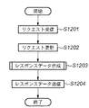
この場合のサーバでの処理を図12を用いて説明する。まずステップS1201で上記のリクエストを受信する。なおこのリクエスト文字列は、“target”によりサーバに格納されているファイル名を指定し、“fsiz”により画像全体の大きさを指定し、“type”により送信データ形式を指定している。 Processing in the server in this case will be described with reference to FIG. First, in step S1201, the above request is received. In this request character string, the file name stored in the server is designated by “target”, the size of the entire image is designated by “fsiz”, and the transmission data format is designated by “type”.
ステップS1202では前記ステップS1201で受信したリクエスト文字列を解析する。これにより要求されているファイル名、返送データの形式、返信する画像データのサイズなどの条件を取得することができる。すなわち本第2の実施形態の場合は、ファイル名“d.jp2”という画像ファイルを、画像全体が256×256画素に収まるサイズになるように要求しており、またその返送形式は、JPIPのprecinct data-binである。ステップS1203では、この条件に当てはまるようにレスポンスデータを生成する部分である。ステップS1204は、ステップS1203で生成したレスポンスデータをクライアントに返送する。 In step S1202, the request character string received in step S1201 is analyzed. This makes it possible to acquire conditions such as the requested file name, the format of return data, and the size of image data to be returned. That is, in the case of the second embodiment, the image file with the file name “d.jp2” is requested to have a size that fits the entire image within 256 × 256 pixels, and the return format is JPIP. precinct data-bin. Step S1203 is a part for generating response data so as to satisfy this condition. In step S1204, the response data generated in step S1203 is returned to the client.
上記ステップS1203の詳細を図13のフローチャートに従って説明する。このフローは、第1の実施形態で説明した部分と大半が同じあるため、同一の処理には同一の番号を付けている。 Details of step S1203 will be described with reference to the flowchart of FIG. Since this flow is mostly the same as the part described in the first embodiment, the same processing is given the same number.
まずステップS1301で今回の要求が、要求するファイルに対して1回目の要求かどうかを判断する。この判断方法は、JPIPの通信をステートフルで行う場合は、1回目か否かはその要求のフローの中で簡単に判断できる。一方ステートレスの場合は、サーバのログ情報などを利用することで判断することができる。このような方法を用いて判断する。 In step S1301, it is determined whether the current request is the first request for the requested file. In this determination method, when JPIP communication is performed in a stateful manner, whether or not this is the first time can be easily determined in the flow of the request. On the other hand, in the case of stateless, it can be determined by using log information of the server. Judgment is made using such a method.
このステップ1301で2回目以降の要求の場合はステップS1303へ、1回目の要求の場合は、ステップS701に進み、返信する画像データを構成するタイル数を計算する。この計算結果からステップS1302で今回要求されている画像データが画像全域を要求しているかどうかを判断する。ここで画像の一部分の要求であれば、ステップS1303に進む。 In the case of the second and subsequent requests in step 1301, the process proceeds to step S1303. In the case of the first request, the process proceeds to step S701, and the number of tiles constituting the image data to be returned is calculated. From this calculation result, it is determined in step S1302 whether or not the image data requested this time requires the entire image. If it is a request for a part of the image, the process advances to step S1303.
一方、画像全域の場合は、ステップS702に進む。ここからは、第1の実施形態と同じであり、違いは第1の実施形態であったステップS705が無くなっていることである。そのため詳細な説明は割愛する。一方ステップS1303は、通常の返信データの作成であり、要求された画像の符号データを返信するために作成すればよい。 On the other hand, in the case of the entire image, the process proceeds to step S702. From here, it is the same as the first embodiment, and the difference is that step S705 which is the first embodiment is eliminated. Therefore, detailed explanation is omitted. On the other hand, step S1303 is creation of normal reply data, which may be created in order to send back the encoded data of the requested image.
以上説明したように、本第2の実施形態によると、クライアントから1回目の要求で、図14のLL(NL=0)’に示す部分の符号データをクライアントに返送する。これ以降の階層の符号データの要求に対するサーバの処理に関しては、通常の場合と同じであるため、説明は割愛する。またクライアント側で受信した符号データをキャッシュする必要があるが、この場合は、この1回目の要求でサーバから返送される符号データを元にキャッシュすれば、これまでどおりのキャッシュ方法で実現できる。 As described above, according to the second embodiment, the code data of the portion indicated by LL (NL = 0) ′ in FIG. 14 is returned to the client by the first request from the client. Since the server processing for the request for the code data of the subsequent layers is the same as the normal case, the description is omitted. Further, it is necessary to cache the code data received on the client side. In this case, if the code data returned from the server in the first request is cached, it can be realized by the conventional cache method.
これにより、クライアントから1回目の要求で、画像全域を要求するリクエストが来た場合、そのコマンドから、要求を発行したクライアント側のアプリケーションで必要な最低解像度の画像サイズを判断し、その画像サイズを返信する符号データの最低解像度になるように符号データを変換してクライアントに返信することで、返信する符号データのバイト数を削減することができ、ネットワーク上でのトラフィックを下げることができる。更には、受信したクライアントでも第1の実施形態で説明したように、このリクエスト以降のデコード時間を短縮することが可能となる。またJPIPを利用する場合は、クライアント側で受信した符号データをキャッシュしなければならないが、階層数が削減されるために、キャッシュしなければならないデータ量も削減することができる。 As a result, when a request for requesting the entire image is received from the client at the first request, the image size of the minimum resolution required by the client-side application that issued the request is determined from the command, and the image size is determined. By converting the code data so as to have the minimum resolution of the code data to be returned and returning it to the client, the number of bytes of the code data to be returned can be reduced, and traffic on the network can be reduced. Furthermore, as described in the first embodiment, the receiving client can shorten the decoding time after this request. When JPIP is used, the code data received on the client side must be cached. However, since the number of layers is reduced, the amount of data that must be cached can also be reduced.
<第3の実施形態>
上記第2の実施形態では、クライアントから発行されるリクエスト文字列からサーバ側で、クライアント側のアプリケーションが必要とする最低解像度の画像サイズを推測する場合を説明したが、これにこれに限るものではなく、例えば、サーバとクライアントで画像データを通信する前に、ネゴシエーションする仕組みを付加して、双方で取り決めを行い、その後その結果を基にリクエスト発行、データの返送を行ってもよい。このネゴシエーションは、JPIPの“vendor capability”として定義して行うことが可能である。
<Third Embodiment>
In the second embodiment, the case where the server side estimates the minimum resolution image size required by the client side application from the request character string issued from the client has been described. However, the present invention is not limited to this. Instead, for example, before the image data is communicated between the server and the client, a negotiation mechanism may be added to make an agreement between the two, and then a request may be issued and data returned based on the result. This negotiation can be defined and defined as “vendor capability” of JPIP.
また、これまでの実施形態では、アプリケーションが必要とする最低解像度の画像サイズと符号データの最低解像度の画像サイズが一致していたが、これに限るものではなく、一致しない場合は、アプリケーションが必要とする最低解像度の画像サイズの画像データを作成するために必要な画像サイズを符号データの最低解像度の画像サイズにすればよいことは容易に推察できる。たとえば、アプリケーションが必要とする最低解像度の画像サイズより大きく、符号データ内の解像度の画像サイズで最低解像度の画像サイズにすればよい。 In the embodiments described so far, the image size of the minimum resolution required by the application and the image size of the minimum resolution of the code data are the same. However, the present invention is not limited to this. It can be easily inferred that the image size required to create image data having the minimum resolution image size should be the minimum resolution image size of the code data. For example, the image size may be larger than the minimum resolution image size required by the application and set to the minimum resolution image size within the code data.
以上説明したように、本実施形態によれば、アプリケーションが使用する最低解像度の画像サイズに符号データの最低解像度を合わせることができ、デコードにかかる時間を短縮することができる。またアプリケーションは、最初に画像を表示する画像サイズから拡大表示する場合など、符号データ内のどの階層符号データをデコードすればよいかも簡単に判断することができる。 As described above, according to the present embodiment, the minimum resolution of the code data can be matched with the minimum resolution image size used by the application, and the decoding time can be shortened. Also, the application can easily determine which hierarchical code data in the code data should be decoded, such as when enlarging and displaying the image size from which the image is displayed first.
またこの符号変換処理は、画像サイズの小さい画像データを対象に行うため、高速に変換できる。さらにはこの変換処理には、DWT(Discrete Wavelet Transform)のLLサブバンドデータへの変換であるため、再エンコード時においても、DWT処理を行うことなく、符号化処理だけを行えばよい。 Since this code conversion process is performed on image data having a small image size, it can be converted at high speed. Furthermore, since this conversion process is a conversion of DWT (Discrete Wavelet Transform) to LL subband data, even during re-encoding, only the encoding process may be performed without performing the DWT process.
更には、符号データをサーバに要求するような場合は、JPIPの仕組みを利用し、サーバがリクエスト文字列を判断することにより、サーバで自動的に判断することも可能である。このためクライアントはサーバで管理されている符号データのエンコード・オプションを意識することなく、アプリケーションが設定する最低解像度の画像データを簡単に入手することができ、さらには階層数を削減することで、サーバから返送する符号の通信量まで削減できる。 Furthermore, when the code data is requested from the server, the server can automatically determine the request character string by using the JPIP mechanism. For this reason, the client can easily obtain the lowest resolution image data set by the application without being aware of the encoding options of the code data managed by the server, and by reducing the number of layers, It is possible to reduce the communication amount of codes returned from the server.
あるいは、サーバとクライアント間で画像データの通信の前に、ネゴシエーションすることも可能であり、これを行うことでより正確に双方の状態などを知らせることが可能となる。さらにはこのネゴシエーションには、JPIPの“vendor capability”として実装も可能であり、JPIPの仕組みの範囲内での実装が可能である。 Alternatively, it is possible to negotiate before communication of image data between the server and the client. By doing this, it becomes possible to more accurately notify both states. Furthermore, this negotiation can be implemented as the “vendor capability” of JPIP, and can be implemented within the scope of the JPIP mechanism.
なお、上記実施形態から明らかなように本発明は、コンピュータで実行するコンピュータプログラムがその主要部にあるわけであるから、当然、そのようなコンピュータプログラムは本発明の範疇に入る。また、通常、コンピュータプログラムはCD−ROM等のコンピュータ可読記憶媒体に格納されていて、それをコンピュータにセットしてシステムにコピーもしくはインストールすることで実行可能になるわけであるから、当然そのようなコンピュータ可読記憶媒体も本発明の範疇に入る。 As is clear from the above-described embodiment, the present invention has a computer program executed by a computer in its main part, and such a computer program naturally falls within the scope of the present invention. In addition, the computer program is usually stored in a computer-readable storage medium such as a CD-ROM, and can be executed by setting it in a computer and copying or installing it in the system. Computer-readable storage media are also within the scope of the present invention.
Claims (8)
出力しようとする画像の出力解像度を判定する判定手段と、
該判定手段で判定された出力解像度に基づき、変換対象の画像符号化データ中の復号すべき符号化データの位置を判定し、当該判定された位置までの符号化データを用いて復号し、出力用画像データを生成する復号手段と、
該復号手段で復号して得られた解像度の画像データを最低解像度として再符号化し、前記復号手段で判定された位置以降の符号化データと接合し、符号化データとして出力する再符号化手段と
を備えることを特徴とする画像処理装置。 To stepwise generate a high resolution image from a low resolution for each tile constituting an image, an image processing apparatus for processing a composed image coded data at a resolution different coded data,
Determining means for determining an output resolution of an image to be output;
Based on the output resolution is determined by said determining means determines the position of the decoding to be encoded data in the image coded data to be converted, and decoded using the coded data up to the determined position, the output Decoding means for generating image data for use;
Re-encoding means for re-encoding the image data of the resolution obtained by decoding by the decoding means as a minimum resolution, joining the encoded data after the position determined by the decoding means, and outputting as encoded data; An image processing apparatus comprising:
更に、前記再符号化手段で再符号化された画像符号化データを前記通信手段を介して要求元のクライアントPCに送信する手段を備えることを特徴とする請求項1に記載の画像処理装置。 The determination unit determines the output resolution included in the request information received through a predetermined communication means from the client terminal on the network,
2. The image processing apparatus according to claim 1, further comprising means for transmitting the image encoded data re-encoded by the re-encoding means to the requesting client PC via the communication means.
前記判定手段は、前記画像表示ウインドウのサイズに基づいて出力解像度を判定することを特徴とする請求項1に記載の画像処理装置。 Furthermore, a display control means for displaying a list window for displaying a file list of image encoded data to be converted and an image display window for displaying a decoded image of the selected image encoded data,
The image processing apparatus according to claim 1, wherein the determination unit determines an output resolution based on a size of the image display window.
出力しようとする画像の出力解像度を判定する判定工程と、
該判定工程で判定された出力解像度に基づき、変換対象の画像符号化データ中の復号すべき符号化データの位置を判定し、当該判定された位置までの符号化データを用いて復号し、出力用画像データを生成する復号工程と、
該復号工程で復号して得られた解像度の画像データを最低解像度として再符号化し、前記復号工程で判定された位置以降の符号化データと接合し、符号化データとして出力する再符号化工程と
を備えることを特徴とする画像処理装置の制御方法。 To stepwise generate a high resolution image from a low resolution for each tile constituting an image, a method of controlling an image processing apparatus for processing a composed image coded data at a resolution different coded data,
A determination step of determining an output resolution of an image to be output;
Based on the output resolution determined in the determination step determines the position of the decoding to be encoded data in the image coded data to be converted, and decoded using the coded data up to the determined position, the output A decoding step for generating image data,
Re-encoding step of re-encoding image data of resolution obtained by decoding in the decoding step as a minimum resolution, joining with encoded data after the position determined in the decoding step, and outputting as encoded data; An image processing apparatus control method comprising:
出力しようとする画像の出力解像度を判定する判定手段と、
該判定手段で判定された出力解像度に基づき、変換対象の画像符号化データ中の復号すべき符号化データの位置を判定し、当該判定された位置までの符号化データを用いて復号し、出力用画像データを生成する復号手段と、
該復号手段で復号して得られた解像度の画像データを最低解像度として再符号化し、前記復号手段で判定された位置以降の符号化データと接合し、符号化データとして出力する再符号化手段
として機能させることを特徴とするコンピュータプログラム。 By computer executes reading, the computer, in order to stepwise generate a high resolution image from a low resolution for each tile constituting the image, the image coded data consists of the resolution-specific coded data A computer program that functions as an image processing apparatus for processing,
Determining means for determining an output resolution of an image to be output;
Based on the output resolution is determined by said determining means determines the position of the decoding to be encoded data in the image coded data to be converted, and decoded using the coded data up to the determined position, the output Decoding means for generating image data for use;
Re-encoding means that re-encodes the image data of the resolution obtained by decoding by the decoding means as the lowest resolution, joins the encoded data after the position determined by the decoding means, and outputs the encoded data A computer program characterized by functioning.
Priority Applications (2)
| Application Number | Priority Date | Filing Date | Title |
|---|---|---|---|
| JP2004324076A JP4371982B2 (en) | 2004-11-08 | 2004-11-08 | Image processing apparatus, control method therefor, computer program, and computer-readable storage medium |
| US11/266,298 US7558430B2 (en) | 2004-11-08 | 2005-11-04 | Apparatus method and computer-readable medium for processing hierarchical encoded image data |
Applications Claiming Priority (1)
| Application Number | Priority Date | Filing Date | Title |
|---|---|---|---|
| JP2004324076A JP4371982B2 (en) | 2004-11-08 | 2004-11-08 | Image processing apparatus, control method therefor, computer program, and computer-readable storage medium |
Publications (3)
| Publication Number | Publication Date |
|---|---|
| JP2006135792A JP2006135792A (en) | 2006-05-25 |
| JP2006135792A5 JP2006135792A5 (en) | 2009-09-10 |
| JP4371982B2 true JP4371982B2 (en) | 2009-11-25 |
Family
ID=36315965
Family Applications (1)
| Application Number | Title | Priority Date | Filing Date |
|---|---|---|---|
| JP2004324076A Expired - Fee Related JP4371982B2 (en) | 2004-11-08 | 2004-11-08 | Image processing apparatus, control method therefor, computer program, and computer-readable storage medium |
Country Status (2)
| Country | Link |
|---|---|
| US (1) | US7558430B2 (en) |
| JP (1) | JP4371982B2 (en) |
Families Citing this family (10)
| Publication number | Priority date | Publication date | Assignee | Title |
|---|---|---|---|---|
| JP4371982B2 (en) * | 2004-11-08 | 2009-11-25 | キヤノン株式会社 | Image processing apparatus, control method therefor, computer program, and computer-readable storage medium |
| JP4716949B2 (en) * | 2005-09-02 | 2011-07-06 | 株式会社リコー | Image processing apparatus and image processing method |
| JP5162103B2 (en) | 2006-05-15 | 2013-03-13 | トヨタ自動車株式会社 | Support control device |
| JP5326234B2 (en) * | 2007-07-13 | 2013-10-30 | ソニー株式会社 | Image transmitting apparatus, image transmitting method, and image transmitting system |
| JP5141886B2 (en) * | 2008-02-28 | 2013-02-13 | 株式会社リコー | Image processing apparatus, image processing method, program, and recording medium |
| JP2011139276A (en) * | 2009-12-28 | 2011-07-14 | Sony Computer Entertainment Inc | Image processor and image processing method |
| JP4848462B2 (en) * | 2010-03-04 | 2011-12-28 | 株式会社モルフォ | Compressed image partial decompression method and image processing apparatus |
| EP3334161B1 (en) * | 2010-09-13 | 2019-08-21 | Sony Interactive Entertainment Inc. | Image processing device, image processing method, and data structure of moving image file |
| US9647835B2 (en) * | 2011-12-16 | 2017-05-09 | Akamai Technologies, Inc. | Terminating SSL connections without locally-accessible private keys |
| CN111859210B (en) * | 2019-04-29 | 2024-04-26 | 百度在线网络技术(北京)有限公司 | Image processing method, device, equipment and storage medium |
Family Cites Families (19)
| Publication number | Priority date | Publication date | Assignee | Title |
|---|---|---|---|---|
| JP3139831B2 (en) * | 1992-05-27 | 2001-03-05 | キヤノン株式会社 | Image editing method and apparatus |
| JPH08275170A (en) * | 1995-03-30 | 1996-10-18 | Canon Inc | Image processing unit |
| JP3210862B2 (en) * | 1996-06-27 | 2001-09-25 | シャープ株式会社 | Image encoding device and image decoding device |
| JP3301340B2 (en) * | 1996-09-04 | 2002-07-15 | ソニー株式会社 | Encoding device, encoding method, decoding device, and decoding method |
| US5838830A (en) * | 1996-09-18 | 1998-11-17 | Sharp Laboratories Of America, Inc. | Vertex-based hierarchical shape representation and coding method and apparatus |
| JPH10257502A (en) * | 1997-03-17 | 1998-09-25 | Matsushita Electric Ind Co Ltd | Hierarchical image encoding method, hierarchical image multiplexing method, hierarchical image decoding method and device therefor |
| AUPO600897A0 (en) * | 1997-04-04 | 1997-05-01 | Canon Information Systems Research Australia Pty Ltd | An efficient method of image compression comprising a low resolution image in the bit stream |
| JP3213582B2 (en) * | 1997-05-29 | 2001-10-02 | シャープ株式会社 | Image encoding device and image decoding device |
| JPH11155144A (en) * | 1997-08-20 | 1999-06-08 | Canon Inc | Image processing system and method therefor, image processor and control method therefor, and computer-readable memory |
| JPH11331618A (en) * | 1998-05-19 | 1999-11-30 | Canon Inc | Image processing unit, image data distribution device, image data distribution system, image data distribution method and storage medium |
| JP4124910B2 (en) * | 1999-05-18 | 2008-07-23 | キヤノン株式会社 | Image data decoding method and apparatus |
| JP2002176359A (en) * | 2000-12-06 | 2002-06-21 | Canon Inc | Information processor, its controlling method, information processing system and computer readable memory |
| US6647149B2 (en) * | 2001-01-03 | 2003-11-11 | Electronics For Imaging, Inc. | Methods and apparatus for securely transmitting and processing digital image data |
| US7581027B2 (en) | 2001-06-27 | 2009-08-25 | Ricoh Co., Ltd. | JPEG 2000 for efficent imaging in a client/server environment |
| US20030067627A1 (en) * | 2001-08-30 | 2003-04-10 | Tomoe Ishikawa | Image processing method and its data cache method |
| US7006699B2 (en) * | 2002-03-27 | 2006-02-28 | Microsoft Corporation | System and method for progressively transforming and coding digital data |
| JP2004040674A (en) | 2002-07-08 | 2004-02-05 | Nec Engineering Ltd | Restoration method for jpeg2000 code data and restoration system for jpeg2000 code data |
| US7580577B2 (en) * | 2002-12-09 | 2009-08-25 | Canon Kabushiki Kaisha | Methods, apparatus and computer products for generating JPEG2000 encoded data in a client |
| JP4371982B2 (en) * | 2004-11-08 | 2009-11-25 | キヤノン株式会社 | Image processing apparatus, control method therefor, computer program, and computer-readable storage medium |
-
2004
- 2004-11-08 JP JP2004324076A patent/JP4371982B2/en not_active Expired - Fee Related
-
2005
- 2005-11-04 US US11/266,298 patent/US7558430B2/en not_active Expired - Fee Related
Also Published As
| Publication number | Publication date |
|---|---|
| US20060098215A1 (en) | 2006-05-11 |
| US7558430B2 (en) | 2009-07-07 |
| JP2006135792A (en) | 2006-05-25 |
Similar Documents
| Publication | Publication Date | Title |
|---|---|---|
| JP4709493B2 (en) | Method and product for communicating compressed digital images | |
| US7558430B2 (en) | Apparatus method and computer-readable medium for processing hierarchical encoded image data | |
| JP4377103B2 (en) | Image processing for JPEG2000 in a server client environment | |
| JP4716645B2 (en) | Document viewing method | |
| JP4603947B2 (en) | Image communication system, server apparatus and control method therefor, and computer program | |
| US7460724B2 (en) | JPP-stream to JPEG 2000 codestream conversion | |
| JP4934462B2 (en) | Method, server and computer program for accessing partial document images | |
| US8209375B2 (en) | Communication of compressed digital images with restricted access and server/client hand-offs | |
| JP2007043673A (en) | Adaptive video compression method of graphical user interface using application metadata | |
| JP2006191159A (en) | Method and apparatus for image processing | |
| US7721971B2 (en) | Image processing system, image processing method and computer readable information recording medium | |
| JP2004297508A (en) | Jpeg 2000 coder and decoder | |
| JP3897691B2 (en) | Scroll display method and apparatus | |
| KR20200106161A (en) | Image processing | |
| JP2007142581A (en) | Image processing method and image processing unit | |
| JP3958198B2 (en) | Image processing method | |
| JP2006339972A (en) | Image processing apparatus and its control method, computer program, and storage medium | |
| JP2007053444A (en) | Server and its control method, computer program, storage medium | |
| JP2007053445A (en) | Server and its control method, computer program, storage medium | |
| JP2006319482A (en) | Image processor and its control method, computer program, and computer-readable storage medium | |
| JP2006345452A (en) | Information processing device, its controlling method, computer program, and storage medium |
Legal Events
| Date | Code | Title | Description |
|---|---|---|---|
| A521 | Request for written amendment filed |
Free format text: JAPANESE INTERMEDIATE CODE: A523 Effective date: 20070718 |
|
| A621 | Written request for application examination |
Free format text: JAPANESE INTERMEDIATE CODE: A621 Effective date: 20070718 |
|
| RD03 | Notification of appointment of power of attorney |
Free format text: JAPANESE INTERMEDIATE CODE: A7423 Effective date: 20070718 |
|
| A521 | Request for written amendment filed |
Free format text: JAPANESE INTERMEDIATE CODE: A523 Effective date: 20090727 |
|
| A977 | Report on retrieval |
Free format text: JAPANESE INTERMEDIATE CODE: A971007 Effective date: 20090819 |
|
| TRDD | Decision of grant or rejection written | ||
| A01 | Written decision to grant a patent or to grant a registration (utility model) |
Free format text: JAPANESE INTERMEDIATE CODE: A01 Effective date: 20090824 |
|
| A01 | Written decision to grant a patent or to grant a registration (utility model) |
Free format text: JAPANESE INTERMEDIATE CODE: A01 |
|
| A61 | First payment of annual fees (during grant procedure) |
Free format text: JAPANESE INTERMEDIATE CODE: A61 Effective date: 20090901 |
|
| FPAY | Renewal fee payment (event date is renewal date of database) |
Free format text: PAYMENT UNTIL: 20120911 Year of fee payment: 3 |
|
| R150 | Certificate of patent or registration of utility model |
Ref document number: 4371982 Country of ref document: JP Free format text: JAPANESE INTERMEDIATE CODE: R150 Free format text: JAPANESE INTERMEDIATE CODE: R150 |
|
| FPAY | Renewal fee payment (event date is renewal date of database) |
Free format text: PAYMENT UNTIL: 20120911 Year of fee payment: 3 |
|
| FPAY | Renewal fee payment (event date is renewal date of database) |
Free format text: PAYMENT UNTIL: 20130911 Year of fee payment: 4 |
|
| LAPS | Cancellation because of no payment of annual fees |