JP5159443B2 - Inkjet recording apparatus and inkjet recording method - Google Patents
Inkjet recording apparatus and inkjet recording method Download PDFInfo
- Publication number
- JP5159443B2 JP5159443B2 JP2008147203A JP2008147203A JP5159443B2 JP 5159443 B2 JP5159443 B2 JP 5159443B2 JP 2008147203 A JP2008147203 A JP 2008147203A JP 2008147203 A JP2008147203 A JP 2008147203A JP 5159443 B2 JP5159443 B2 JP 5159443B2
- Authority
- JP
- Japan
- Prior art keywords
- recording
- temperature
- scans
- head
- recording head
- Prior art date
- Legal status (The legal status is an assumption and is not a legal conclusion. Google has not performed a legal analysis and makes no representation as to the accuracy of the status listed.)
- Active
Links
Images


Classifications
-
- B—PERFORMING OPERATIONS; TRANSPORTING
- B41—PRINTING; LINING MACHINES; TYPEWRITERS; STAMPS
- B41J—TYPEWRITERS; SELECTIVE PRINTING MECHANISMS, i.e. MECHANISMS PRINTING OTHERWISE THAN FROM A FORME; CORRECTION OF TYPOGRAPHICAL ERRORS
- B41J29/00—Details of, or accessories for, typewriters or selective printing mechanisms not otherwise provided for
- B41J29/38—Drives, motors, controls or automatic cut-off devices for the entire printing mechanism
- B41J29/393—Devices for controlling or analysing the entire machine ; Controlling or analysing mechanical parameters involving printing of test patterns
-
- B—PERFORMING OPERATIONS; TRANSPORTING
- B41—PRINTING; LINING MACHINES; TYPEWRITERS; STAMPS
- B41J—TYPEWRITERS; SELECTIVE PRINTING MECHANISMS, i.e. MECHANISMS PRINTING OTHERWISE THAN FROM A FORME; CORRECTION OF TYPOGRAPHICAL ERRORS
- B41J2/00—Typewriters or selective printing mechanisms characterised by the printing or marking process for which they are designed
- B41J2/005—Typewriters or selective printing mechanisms characterised by the printing or marking process for which they are designed characterised by bringing liquid or particles selectively into contact with a printing material
- B41J2/01—Ink jet
- B41J2/015—Ink jet characterised by the jet generation process
- B41J2/04—Ink jet characterised by the jet generation process generating single droplets or particles on demand
- B41J2/045—Ink jet characterised by the jet generation process generating single droplets or particles on demand by pressure, e.g. electromechanical transducers
- B41J2/04501—Control methods or devices therefor, e.g. driver circuits, control circuits
- B41J2/04515—Control methods or devices therefor, e.g. driver circuits, control circuits preventing overheating
-
- B—PERFORMING OPERATIONS; TRANSPORTING
- B41—PRINTING; LINING MACHINES; TYPEWRITERS; STAMPS
- B41J—TYPEWRITERS; SELECTIVE PRINTING MECHANISMS, i.e. MECHANISMS PRINTING OTHERWISE THAN FROM A FORME; CORRECTION OF TYPOGRAPHICAL ERRORS
- B41J2/00—Typewriters or selective printing mechanisms characterised by the printing or marking process for which they are designed
- B41J2/005—Typewriters or selective printing mechanisms characterised by the printing or marking process for which they are designed characterised by bringing liquid or particles selectively into contact with a printing material
- B41J2/01—Ink jet
- B41J2/015—Ink jet characterised by the jet generation process
- B41J2/04—Ink jet characterised by the jet generation process generating single droplets or particles on demand
- B41J2/045—Ink jet characterised by the jet generation process generating single droplets or particles on demand by pressure, e.g. electromechanical transducers
- B41J2/04501—Control methods or devices therefor, e.g. driver circuits, control circuits
- B41J2/04563—Control methods or devices therefor, e.g. driver circuits, control circuits detecting head temperature; Ink temperature
-
- B—PERFORMING OPERATIONS; TRANSPORTING
- B41—PRINTING; LINING MACHINES; TYPEWRITERS; STAMPS
- B41J—TYPEWRITERS; SELECTIVE PRINTING MECHANISMS, i.e. MECHANISMS PRINTING OTHERWISE THAN FROM A FORME; CORRECTION OF TYPOGRAPHICAL ERRORS
- B41J2/00—Typewriters or selective printing mechanisms characterised by the printing or marking process for which they are designed
- B41J2/005—Typewriters or selective printing mechanisms characterised by the printing or marking process for which they are designed characterised by bringing liquid or particles selectively into contact with a printing material
- B41J2/01—Ink jet
- B41J2/015—Ink jet characterised by the jet generation process
- B41J2/04—Ink jet characterised by the jet generation process generating single droplets or particles on demand
- B41J2/045—Ink jet characterised by the jet generation process generating single droplets or particles on demand by pressure, e.g. electromechanical transducers
- B41J2/04501—Control methods or devices therefor, e.g. driver circuits, control circuits
- B41J2/04573—Timing; Delays
-
- B—PERFORMING OPERATIONS; TRANSPORTING
- B41—PRINTING; LINING MACHINES; TYPEWRITERS; STAMPS
- B41J—TYPEWRITERS; SELECTIVE PRINTING MECHANISMS, i.e. MECHANISMS PRINTING OTHERWISE THAN FROM A FORME; CORRECTION OF TYPOGRAPHICAL ERRORS
- B41J2/00—Typewriters or selective printing mechanisms characterised by the printing or marking process for which they are designed
- B41J2/005—Typewriters or selective printing mechanisms characterised by the printing or marking process for which they are designed characterised by bringing liquid or particles selectively into contact with a printing material
- B41J2/01—Ink jet
- B41J2/015—Ink jet characterised by the jet generation process
- B41J2/04—Ink jet characterised by the jet generation process generating single droplets or particles on demand
- B41J2/045—Ink jet characterised by the jet generation process generating single droplets or particles on demand by pressure, e.g. electromechanical transducers
- B41J2/04501—Control methods or devices therefor, e.g. driver circuits, control circuits
- B41J2/0458—Control methods or devices therefor, e.g. driver circuits, control circuits controlling heads based on heating elements forming bubbles
Description
本発明は、記録ヘッドからインクを吐出して記録媒体への記録を行う記録装置および記録方法に関し、詳しくは、インクの吐出により昇温する記録ヘッドの温度制御を行う記録装置および記録方法に関する。 The present invention relates to a recording apparatus and a recording method for performing recording on a recording medium by ejecting ink from a recording head, and more particularly to a recording apparatus and a recording method for controlling the temperature of a recording head that raises the temperature by ejecting ink.
近年、コンピュータやインターネットの普及等に伴い、画像を出力する出力機器として、プリンタ、複写機、ファクシミリ等の記録装置が、オフィスや一般家庭に急速に普及している。このような、記録装置に採用されている主な記録方式としては、電子写真方式、インクジェット方式、サーマル方式等が挙げられる。これらの記録方式のなかでもインクジェット方式を採る記録装置(インクジェット記録装置)は、紙、OHP用シートやフィルムだけでなく、布、段ボール、陶器、金属等といった様々な材質の媒体への記録が可能である。さらに、平面的な媒体だけでなく凹凸や曲面がある媒体への記録、媒体のエッジ部への記録なども可能であることから、インクジェット記録装置は、パーソナルユースのみならず、業務用としても広く活用されている。また、インクジェット記録装置は、記録ヘッドの小型化が比較的容易で、高精細な画像を高速に記録でき、ランニングコストが安く、記録時の騒音が少なく、カラー画像の記録を簡易な構成で実現できるという、数々の利点を有している。 In recent years, with the spread of computers and the Internet, recording devices such as printers, copiers, and facsimiles are rapidly spreading in offices and general households as output devices for outputting images. As main recording methods employed in such a recording apparatus, there are an electrophotographic method, an ink jet method, a thermal method, and the like. Among these recording methods, the recording device (inkjet recording device) adopting the ink jet method can record not only on paper, OHP sheets and films, but also on media of various materials such as cloth, cardboard, earthenware, and metal. It is. Furthermore, since recording on not only flat media but also media with irregularities and curved surfaces and recording on the edges of media is possible, inkjet recording devices are widely used not only for personal use but also for business use. It is utilized. In addition, the inkjet recording device is relatively easy to downsize the recording head, can record high-definition images at high speed, has low running costs, has low noise during recording, and has a simple configuration for recording color images. It has many advantages that it can.
こうしたインクジェット記録装置に搭載する記録ヘッドとしては、現在、電気熱変換素子(ヒータ)を用いるもの、ピエゾなどの電気機械変換素子を使用するものなどが知られている。このうち、熱エネルギを利用してインクを吐出するタイプの記録ヘッドは、半導体製造プロセスによって、基板上に電気熱変換体や電極を製膜し、その後、液路壁、天板等を形成することにより製造されている。このため、インクを滴として吐出するための個々の記録素子(ノズル、吐出口とも称する)を比較的高密度に製造することができ、一層のコンパクト化を図ることができる。さらに、熱エネルギを利用してインクを吐出する記録ヘッドは、吐出の応答周波数にも優れており、高精細な画像を高速に記録しようとする近年の需要に対応するに好適なものとなっている。このような記録ヘッドでは、インクを供給するための液路と、当該液路内のインクに膜沸騰を生じさせるための電気熱変換素子を備えた記録素子(ノズル)を、高密度に複数集積配置させた構成が一般的である。 As recording heads mounted on such an ink jet recording apparatus, there are currently known ones that use electrothermal conversion elements (heaters), and those that use electromechanical conversion elements such as piezos. Among these, a recording head of a type that ejects ink using thermal energy forms an electrothermal transducer and electrodes on a substrate by a semiconductor manufacturing process, and then forms a liquid path wall, a top plate, and the like. It is manufactured by. For this reason, individual recording elements (also referred to as nozzles and ejection openings) for ejecting ink as droplets can be manufactured at a relatively high density, and further downsizing can be achieved. Furthermore, a recording head that ejects ink using thermal energy has excellent ejection response frequency, and is suitable for meeting recent demands for recording high-definition images at high speed. Yes. In such a recording head, a plurality of recording elements (nozzles) including a liquid path for supplying ink and an electrothermal conversion element for causing film boiling in the ink in the liquid path are integrated at high density. Arranged configurations are common.
しかし、複数の記録素子を高密度に配置した記録ヘッドでは、個々の記録素子に備えられた電気熱変換素子を急激に発熱させることで吐出のためのエネルギを生み出しているので、吐出を重ねるほどに記録ヘッドの蓄熱が進み、この蓄熱が問題となる場合がある。
例えば、記録ヘッドの蓄熱が進むと、各液路に供給するインクを一時貯留する共通液室内のインク温度も上昇し、インク中には溶存気体が析出する。さらに、個々の液路で発生した小さな気泡は蓄熱とともに徐々に成長し、やがて各液路と連通した共通液室内に存在するようになる。このようになると、この大きな気泡がインクタンクから共通液室へのインク供給、ひいては共通液室から各液路へのインクの供給を妨害し、各記録素子の吐出口からのインク吐出を妨害することとなる。このように、電気熱変換素子に対し画像データに従った電圧パルスを印加しても、個々の記録素子から十分なインク滴の吐出が行われないことを一般に不吐出と称す。インクジェット記録ヘッドにおいては、過昇温の状態になると、このような不吐出の発生によって画像品位に影響を与えたり、記録ヘッドの破損を招いたりするおそれがある。このような蓄熱問題は、高速記録や高解像度の画像出力を実現しようとするほど、吐出口を高密度に配列した記録ヘッドを高周波数で駆動するので、顕著に現れやすくなる。
However, in a recording head in which a plurality of recording elements are arranged at high density, energy for ejection is generated by abruptly generating heat from the electrothermal conversion elements provided in the individual recording elements. In some cases, the heat storage of the recording head advances, and this heat storage may cause a problem.
For example, as the heat storage of the recording head proceeds, the ink temperature in the common liquid chamber that temporarily stores the ink supplied to each liquid path also rises, and dissolved gas is deposited in the ink. Furthermore, small bubbles generated in the individual liquid passages gradually grow with heat accumulation, and eventually exist in a common liquid chamber communicating with each liquid passage. In this case, the large bubbles obstruct the ink supply from the ink tank to the common liquid chamber, and hence the ink supply from the common liquid chamber to each liquid path, and the ink ejection from the ejection port of each recording element. It will be. In this way, even when a voltage pulse according to image data is applied to the electrothermal conversion element, the fact that sufficient ink droplets are not ejected from the individual recording elements is generally referred to as non-ejection. In an ink jet recording head, if the temperature rises excessively, the occurrence of such non-ejection may affect the image quality or cause damage to the recording head. Such a heat storage problem becomes more prominent as the recording head in which the discharge ports are arranged at a high density is driven at a high frequency as high-speed recording and high-resolution image output are realized.
以上説明したような蓄熱問題に起因する弊害を回避するために、記録中に記録ヘッドの温度を検出し、検出された温度を所定の閾値と比較することによって、記録動作を制御する方法が知られている。例えば、検出温度が閾値より高い場合に、記録ヘッドの駆動周波数(吐出周波数)を低減し、蓄熱を抑制する方法がある。また、記録ヘッドの主走査と記録媒体の副走査とを間欠的に繰り返して画像を形成するシリアルタイプのインクジェット記録装置では、次の記録走査を実行する前に待機時間を設け、記録ヘッドの温度の低下を促す方法も有効な方法とされている(特許文献1参照)。 In order to avoid the adverse effects caused by the heat storage problem as described above, a method for controlling the recording operation by detecting the temperature of the recording head during recording and comparing the detected temperature with a predetermined threshold is known. It has been. For example, when the detected temperature is higher than a threshold value, there is a method of suppressing the heat storage by reducing the drive frequency (ejection frequency) of the recording head. In addition, in a serial type ink jet recording apparatus that forms an image by intermittently repeating the main scan of the recording head and the sub-scan of the recording medium, a standby time is provided before the next recording scan is performed, and the temperature of the recording head is set. A method for promoting a decrease in the above is also an effective method (see Patent Document 1).
また、現時点での検出温度と次の主走査の画像データとに基づいて、次の主走査終了後の記録ヘッドの温度を推定し、当該推定温度に従って待機時間を設定する方法も開示されている(特許文献2参照)。 Also disclosed is a method of estimating the temperature of the recording head after the end of the next main scan based on the detected temperature at the current time and the image data of the next main scan, and setting the standby time according to the estimated temperature. (See Patent Document 2).
以上説明した方法を採用することにより、記録ヘッドが過昇温状態なることを抑制することが可能である。従って、上記方法によれば、インクの吐出が不安定になって画像品位に影響を与えたり、記録ヘッドの破損を招くような問題を回避することは可能である。 By adopting the method described above, it is possible to suppress the recording head from being overheated. Therefore, according to the above method, it is possible to avoid the problem that the ink ejection becomes unstable and the image quality is affected or the recording head is damaged.
しかしながら、上述のように記録ヘッドの駆動周波数を制御する方式においては、記録ヘッドが過昇温状態となることを抑制できる反面、次のような問題が新たに発生する。すなわち、検出温度が閾値より高い場合に記録ヘッドの駆動周波数(吐出周波数)を低減する方法を採用した場合には、記録ヘッドの駆動周波数に合わせて記録ヘッドの記録媒体に対する相対速度も低減しなければならない。このように、同一ページ内で駆動周波数や相対速度を変更する制御は、複雑な駆動機構の構成や駆動制御回路を要することになる。よって、装置全体のコストが上がってしまうという問題が生じるのである。 However, in the method of controlling the drive frequency of the recording head as described above, it is possible to suppress the recording head from being overheated, but the following problem newly arises. In other words, when a method of reducing the drive frequency (discharge frequency) of the print head when the detected temperature is higher than the threshold value, the relative speed of the print head to the print medium must be reduced according to the drive frequency of the print head. I must. As described above, the control for changing the drive frequency and the relative speed in the same page requires a complicated drive mechanism configuration and drive control circuit. Therefore, there arises a problem that the cost of the entire apparatus increases.
これに対し、特許文献1および特許文献2に示すような、各主走査の間に待機時間を設ける方法の場合には、さほど複雑な構成は必要とされない。しかし、これらの方法においては、先の記録走査と続く記録走査との間に待機時間を設けることで記録された画像において弊害が確認された。具体的には、待機時間を挟んで記録された領域の濃度や色相がその他の領域の濃度や色相と異なり、その差異が画像上において濃度ムラや色相ムラとして視認されるという問題が生じる。
On the other hand, in the method of providing a standby time between each main scan as shown in
以下に、マルチパス記録を行ったインクジェット記録装置において、上記濃度ムラや色相ムラなどの現象が発生する原因を説明する。インクジェット記録装置に搭載する記録ヘッドには、複数の記録素子が高密度に配列されており、画像データに応じて個々の記録素子からインクが吐出される。但し、複数の記録素子間には、記録ヘッドの製造工程上ある程度のばらつきが含まれてしまうので、それぞれの記録素子からのインク吐出量や吐出方向は完全に揃った状態にはなり難い。このように記録素子が不揃いの状態の記録ヘッドによる1回の記録走査で記録された画像は、個々の記録素子の吐出特性が顕著に現れ、すじやムラなどの画像弊害が発生し、これが目視によって認識されてしまう。マルチパス記録方法は、このような画像弊害を低減するために採用される記録方法である。 Hereinafter, the cause of the phenomenon such as density unevenness and hue unevenness in the ink jet recording apparatus that performs multi-pass recording will be described. A recording head mounted on the ink jet recording apparatus has a plurality of recording elements arranged at high density, and ink is ejected from the individual recording elements in accordance with image data. However, since a certain amount of variation is included in the manufacturing process of the recording head between the plurality of recording elements, the ink ejection amount and ejection direction from each recording element are unlikely to be perfectly aligned. As described above, an image recorded by one recording scan by the recording head in which the recording elements are unevenly appears, the ejection characteristics of the individual recording elements appear remarkably, and image defects such as streaks and unevenness occur. Will be recognized by. The multi-pass recording method is a recording method that is employed in order to reduce such image problems.
マルチパス記録方法では、記録ヘッドが1回の主走査で記録可能な画像データを複数に分割し、所定量の副走査を挟んだ複数回の主走査によって画像を形成する。すなわち、1回の主走査で1つの記録素子によって記録可能なラインが、マルチパス記録方法では、複数回の主走査によって複数の記録素子を用いて形成される。よって、当該ラインにおいては1つの記録素子の吐出特性の影響が低減され、各記録素子の吐出特性は分散される。その結果、画像全体においては、極端なすじやムラが現れにくくなり、滑らかな画像を得ることができる。 In the multi-pass recording method, image data that can be recorded by the recording head in one main scan is divided into a plurality of images, and an image is formed by a plurality of main scans sandwiching a predetermined amount of sub-scanning. That is, in the multipass printing method, a line that can be printed by one printing element in one main scanning is formed by using a plurality of printing elements in a plurality of main scannings. Therefore, in the line, the influence of the ejection characteristics of one printing element is reduced, and the ejection characteristics of each printing element are dispersed. As a result, extreme streaks and unevenness are less likely to appear in the entire image, and a smooth image can be obtained.
このようなマルチパス記録方法では、マルチパス数を様々に設定することができる。例えば、2パスのマルチパス記録方法であれば、1回の主走査で記録可能な画像データを2つに分割し、2回の主走査によって画像を形成する。Nパスのマルチパス記録方法であれば、1回の主走査で記録可能な画像データをN個に分割し、N回の主走査によって画像を形成する。Nの値が大きいほど、1つのラインに対する1つの記録素子の吐出特性の影響が緩和され、画像全体が滑らかになる。 In such a multi-pass recording method, the number of multi-passes can be set variously. For example, in the case of a two-pass multi-pass printing method, image data that can be printed by one main scan is divided into two, and an image is formed by two main scans. In the N-pass multi-pass printing method, image data that can be printed by one main scan is divided into N pieces, and an image is formed by N main scans. The larger the value of N, the less the influence of the ejection characteristics of one printing element on one line, and the smoother the entire image.
マルチパス記録方法を行ったときに、N回の主走査間の時間差が発生する場合と、発生しない場合とでは、記録された画像の濃度が異なる。これは、2滴のインクが付与されるときに、後のインクが付与されるときの先に付与されたインクの記録媒体への浸透度合いによって、先に付与されるインクと後に付与されるインクそれぞれの記録媒体に対する浸透度合いが異なる。そのため、インクの浸透度合いによって記録画像の濃度も異なってしまう。つまり、先の主走査と次の主走査との間に待機時間が設けられることで、これらの記録走査によって記録された画像の濃度や色相が他の部分と異なってしまう。これらの現象は、適用するインクの種類や記録媒体の種類によって現れ方は様々ではある。しかし、少なくとも当該時間差によって画像濃度や色相が影響を受けることは確認されている。 When the multi-pass printing method is performed, the density of the recorded image differs depending on whether or not a time difference between N main scans occurs. This is because when two drops of ink are applied, the ink that is applied first and the ink that is applied later are determined depending on the degree of penetration of the previously applied ink into the recording medium when the subsequent ink is applied. The degree of penetration with respect to each recording medium is different. Therefore, the density of the recorded image varies depending on the degree of ink penetration. That is, by providing a waiting time between the previous main scan and the next main scan, the density and hue of the image recorded by these recording scans differ from those of other portions. These phenomena vary in appearance depending on the type of ink to be applied and the type of recording medium. However, it has been confirmed that image density and hue are affected at least by the time difference.
このように記録ヘッドの検出温度が閾値を超えたか否かに応じて各記録走査間の待機時間を変更する方法では、多くの待機時間経過後に記録走査された領域だけが、他の領域に比べて異なった濃度や色相となり、これがムラとして視認されてしまう問題が生じる。なお、このような問題は、多色記録(カラー記録)の場合だけでなく、単色記録を行う場合にも発生する。つまり、単色記録の場合には、濃度ムラが発生し、多色記録の場合には濃度ムラおよび色相ムラが発生する。 In this way, in the method of changing the waiting time between the printing scans depending on whether or not the detected temperature of the printing head exceeds the threshold value, only the area that has been scanned and scanned after the passage of many waiting times is compared with the other areas. Therefore, there arises a problem that different densities and hues are visually recognized as unevenness. Such a problem occurs not only in the case of multicolor recording (color recording) but also in the case of performing monochromatic recording. That is, density unevenness occurs in the case of monochromatic recording, and density unevenness and hue unevenness occurs in the case of multicolor recording.
本発明は上記問題点を鑑みてなされたものである。すなわち、本発明の目的は、複雑な構造や制御を必要とせず、記録ヘッドの昇温に起因する濃度ムラや色相ムラが画像内に発生することを低減することが可能なインクジェット記録装置およびインクジェット記録方法の提供にある。 The present invention has been made in view of the above problems. That is, an object of the present invention is an ink jet recording apparatus and an ink jet which can reduce the occurrence of density unevenness and hue unevenness due to temperature rise of the recording head without requiring a complicated structure or control. To provide a recording method.
上記目的を達成するために本発明のインクジェット記録装置は、以下の構成を備える。
すなわち、本発明の第1の形態は、記録ヘッドからインクを吐出させることにより記録を行うインクジェット記録装置であって、前記記録ヘッドを記録媒体上の同一領域に対して相対的に複数回走査させる走査手段と、前記記録ヘッドの温度を検出する検出手段と、前記検出手段により検出された温度に基づいて、前記記録ヘッドの走査開始前に待機すべき走査の回数と、前記回数分の記録ヘッドの走査それぞれにおける待機時間とを設定する設定手段と、を備え、前記設定手段は、前記待機時間を、待機制御を実施した後に記録された画像領域と待機制御されずに記録された隣接領域との色差が生じない時間であり、かつ設定された走査回数の待機制御を実施したときに記録ヘッドの過昇温を抑制できる時間となるように設定することを特徴とする。
In order to achieve the above object, an ink jet recording apparatus of the present invention comprises the following arrangement.
That is, the first embodiment of the present invention provides an ink jet recording apparatus for recording by ejecting ink from the record head, relatively multiple scans to the same area on the recording medium the recording head Scanning means, detecting means for detecting the temperature of the recording head, and the number of scans to be waited before starting the scanning of the recording head based on the temperature detected by the detecting means, and recording for the number of times Setting means for setting a standby time in each scanning of the head, and the setting means sets the standby time to an image area recorded after performing standby control and an adjacent area recorded without standby control. JP that color difference is not time occurs, and sets the standby control of the set number of scans such that the time to suppress the excessive rise in temperature of the recording head when the implementation and To.
本発明の第2の形態は、記録素子を備えた記録ヘッドを走査させつつ前記記録ヘッドからインクを吐出させることによって記録を行う記録方法であって、前記記録ヘッドの温度を検出する工程と、前記検出された温度に基づいて、前記記録ヘッドの走査開始前に前記記録ヘッドを待機させる走査の回数と、前記回数分の記録ヘッドの走査それぞれにおける待機時間とを設定する設定する工程と、を備え、前記設定する工程では、前記待機時間を待機制御を実施した後に記録された画像領域と待機制御されずに記録された隣接領域との色差が生じない時間であり、かつ設定された走査回数の待機制御を実施したときに記録ヘッドの過昇温を抑制できる時間となるように設定することを特徴とする。 Second embodiment of the present invention is a recording method for recording by ejecting ink from the recording head while scanning a recording head having a record element, and detecting a temperature of said recording head Setting the number of scans to wait for the print head before the scan of the print head starts based on the detected temperature, and the waiting time for each scan of the print head for the number of times; and The waiting time is a time during which no color difference occurs between an image area recorded after performing standby control and an adjacent area recorded without standby control, and set scanning. It is characterized in that the time is set so that the overheating of the recording head can be suppressed when the standby control of the number of times is performed .
本発明によれば、記録中に記録ヘッドの温度が上昇した場合でも、それ以降に開始される複数の走査の前に待機時間が分散されて設けられる。このため、それぞれの記録走査において記録された複数回の走査によって完成される各領域の間には、大きな色相ムラ濃度ムラなどが発生しない。 According to the present invention, even when the temperature of the recording head rises during recording, the waiting time is distributed before a plurality of scans started thereafter. For this reason, large hue unevenness density unevenness or the like does not occur between the regions completed by a plurality of scans recorded in each recording scan.
(第1の実施形態)
以下、添付図面を参照して本発明の好適な実施形態について詳細に説明する。なお、本明細書において、「記録」とは、文字、図形等有意の情報を記録媒体上に形成する場合のみならず、無意の情報を記録媒体上に形成することも含む。また、「記録媒体」とは、一般的な記録装置で用いられる紙のみならず、布、プラスチック・フィルム、金属板、ガラス、セラミックス、木材、皮革等、インクを受容可能なものも表すものとする。さらに、「インク」とは、上記「記録」の定義と同様広く解釈されるべきもので、記録媒体上に付与されることによって、画像、模様、パターン等の形成を表すものとする。
(First embodiment)
Hereinafter, preferred embodiments of the present invention will be described in detail with reference to the accompanying drawings. In this specification, “recording” includes not only the formation of significant information such as characters and graphics on a recording medium, but also the formation of inadvertent information on the recording medium. “Recording medium” represents not only paper used in general recording apparatuses but also cloth, plastic film, metal plate, glass, ceramics, wood, leather, and the like that can accept ink. To do. Further, “ink” should be interpreted widely as the definition of “recording”, and represents the formation of an image, a pattern, a pattern, etc. by being applied on a recording medium.
図1は、本実施形態に適用可能なインクジェット記録装置の内部機構を説明するための概略斜視図である。図において、1は搬送モータである。搬送モータ1の駆動により、プラテンローラ2が図の矢印R方向に回転し、記録媒体Mが矢印F方向に搬送される。記録媒体Mの搬送方向F(副走査方向)と直交する方向には、ガイドシャフト3aおよび3bが平行に配設されている。インクジェット記録ヘッド5を搭載したキャリッジ4(走査手段)は、ガイドシャフト3aおよび3bに案内支持されながら、キャリッジモータ6の駆動によって図中矢印S方向(主走査方向)に往復移動(往復走査)する。キャリッジ4に搭載された記録ヘッド5は、キャリッジ4の移動走査中に記録データに応じてインクの吐出を実行し、記録媒体への記録が行われる。本実施形態では、記録ヘッド5が往路に沿って移動する場合と、復路に沿って移動する場合のいずれにおいてもインクを吐出して記録媒体に記録を行う、いわゆる双方向記録方式を採る。なお、記録ヘッド5が走査しつつインクを吐出して記録媒体上に記録を行う動作を、以下の説明において記録走査とも言う。記録ヘッド5による1回の記録走査が行われると、記録媒体Mは搬送モータ1によって所定量搬送される。
FIG. 1 is a schematic perspective view for explaining an internal mechanism of an ink jet recording apparatus applicable to this embodiment. In the figure, 1 is a transport motor. By driving the
本実施形態で適用するインクジェット記録ヘッド5には、副走査方向に1200dpi(ドット/インチ;参考値)のピッチで、1280個の吐出口が配列されている。各吐出口に連通したインク流路(液路)内には、画像データに応じて生成される電気信号を受けて熱を発生する電気熱変換体が設けられている。この電気熱変換体から発生される熱により、インクは局所的に加熱されて膜沸騰を生じ、その際に生じる圧力によってインクが吐出口から吐出される。なお、以下の説明において、インクを吐出する吐出口、これに連通する液路、および液路内に設けられた電気熱変換体をノズル(記録素子)と称す。また、記録ヘッド5において、上記電気熱変換体が設けられた基板上には、記録ヘッド5の温度を検知するヘッド温検出手段としてのダイオードセンサ50(図2参照)が設けられている。
In the
図2は、本実施形態におけるインクジェット記録装置の制御系の構成を説明するためのブロック図である。図において、20はホスト装置Hとインクジェット記録装置本体側との間で画像データや制御コマンド等のデータ送受信を行うためのインターフェースである。21は種々の演算、判断および設定などの処理を行うと共に、記録装置全体の各種制御をも実行するMPUであり、このMPU21が制御を行うためのプログラムや固定データはROM22に格納されている。23は各種データ(記録ヘッド5に供給すべき記録データ等)を一時的に格納したり、MPU21が行う処理のワークエリアとして利用されたりするDRAMである。なお、前記MPU21、ROM22およびDRAM23により、本発明の制御手段、待機制御手段、走査回数設定手段および待機時間設定手段を構成している。
FIG. 2 is a block diagram for explaining a configuration of a control system of the ink jet recording apparatus according to the present embodiment. In the figure,
24は記録ヘッド5に対する記録データの供給制御を行うゲートアレイである。このゲートアレイ24は、インターフェース20、MPU21、DRAM23間のデータ転送の制御も行う。25はキャリッジモータ6を駆動するためのモータドライバであり、26は搬送モータ1を駆動するためのモータドライバである。また、27は記録ヘッド5を駆動するためのヘッドドライバである。また、記録ヘッド5の温度を検出するダイオードセンサ50からの出力データ(温度値)はMPU21へ送られるようになっている。
以上説明した記録装置を用いて、記録を実行する場合のシーケンスを以下に具体的に説明する。
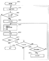
図3は、本実施形態の記録装置において、1ページ分の画像を記録する際にMPU21が実行する一連の工程を説明するためのフローチャートである。
まず、ステップS301において記録が開始されると、ホスト装置Hからは制御データを含む画像データがインターフェース20およびゲートアレイ24を介してMPU21に入力される。ステップS302では、MPU21が、ダイオードセンサ50によって検出された記録ヘッド5の温度(以下、ヘッド温度THと称する)の取得を行う。次いで、このヘッド温取得工程において取得したヘッド温度THと予めROM22に格納されている所定の閾値温度(以下、待機開始温度TWと称する)とを比較する(ステップS303)。ここで、取得したヘッド温度THが待機開始温度TW以下(閾値以下)である場合には、ステップS306に進み、1回分の記録走査を実行する。
A sequence in the case of performing recording using the recording apparatus described above will be specifically described below.
FIG. 3 is a flowchart for explaining a series of steps executed by the
First, when recording is started in step S <b> 301, image data including control data is input from the host apparatus H to the
一方、ステップS303において取得したヘッド温度THが待機開始温度TWよりも高いと判断された場合には、MPU21がフラグ(待機フラグ)をONする(ステップS304)。なお、待機開始温度TWは、不吐出などの問題を発生させる温度までヘッド温が上昇するのを防ぐために、記録動作を事前に一時中断したほうが良いと判断される温度に設定されている。具体的には、本実施形態に適用可能な記録装置においては待機温度を66℃としている。
On the other hand, when it is determined that the head temperature TH acquired in step S303 is higher than the standby start temperature TW, the
さらにMPU21は、以降の記録走査において記録走査前にキャリッジの走査を待機させるべき時間(待機時間)、および記録走査前に待機時間を設けるべき記録走査の回数(設定走査回数)を定め、その待機時間だけ記録走査を待機させる(ステップS305)。本実施形態では、ステップS305において実施する待機時間および待機させるべき記録走査の回数の設定は、図4に示すテーブルに従って行う。なお、上記のようにキャリッジの走査の開始を待機させる制御を以下の説明においては、待機制御という。
Further, the
図4に示すように、本実施形態の記録装置では、ステップS303で検出されたヘッド温度THに応じて、待機時間および設定走査回数を定める。図4に示すテーブルでは、ヘッド温度が66℃〜70℃、71℃〜75℃、76℃以上、の3段階に分かれており、各段階に対応して個別の待機制御を行うようになっている。例えば、ステップS302で検出されたヘッド温度THが66℃〜70℃の範囲内であった場合には、それ以降に順次開始される4回の記録走査において、各々の記録走査の開始前に0.3秒の待機時間を設けるようになっている。また、検出されたヘッド温度THが71℃〜75℃の範囲内であった場合には、6回の記録走査に対して0.3秒の待機時間を設け、76℃以上であった場合には、8回の記録走査に対して0.3秒の待機時間を設ける。このように、本実施形態では、いずれの温度範囲においても、各記録走査の前に設ける待機時間は、一律0.3秒に設定されている。なお、このようなヘッド温度THに対する待機時間およびその設定走査回数を表すテーブルのデータは、予めROM22内に格納されており、MPU21は当該テーブルを参照することにより待機時間および設定走査回数を定める。そして、テーブルに基づいて定められた設定走査回数および待機時間に基づいて、キャリッジ4の走査を待機させる。
As shown in FIG. 4, in the printing apparatus of the present embodiment, the standby time and the set number of scans are determined according to the head temperature TH detected in step S303. In the table shown in FIG. 4, the head temperature is divided into three stages of 66 ° C. to 70 ° C., 71 ° C. to 75 ° C., and 76 ° C. or more, and individual standby control is performed corresponding to each step. Yes. For example, when the head temperature TH detected in step S302 is in the range of 66 ° C. to 70 ° C., in the four recording scans sequentially started thereafter, the head temperature TH is 0 before the start of each recording scan. A waiting time of 3 seconds is provided. When the detected head temperature TH is in the range of 71 ° C. to 75 ° C., a standby time of 0.3 seconds is provided for six recording scans, and the detected head temperature TH is 76 ° C. or higher. Provides a waiting time of 0.3 seconds for eight printing scans. Thus, in this embodiment, in any temperature range, the standby time provided before each printing scan is uniformly set to 0.3 seconds. Note that data of a table indicating such a standby time with respect to the head temperature TH and the set scanning number thereof is stored in the
ステップS305において、設定した待機時間だけキャリッジ4の走査開始を待機させた後、MPU21は1回分の記録走査を実行する(ステップS306)。すなわちMPU21は、キャリッジモータ6を駆動することによりキャリッジ4を移動させながら、ヘッドドライバ27を駆動することによって記録ヘッド5が記録データに従ったインクの吐出を行う。
In step S305, after waiting for the
ステップS305およびステップS306によって1行分の記録走査が完了すると、ステップS307へ進み、直前に行った記録走査で1ページ分の画像データの記録が完了したか否かを判断する。ここで、記録すべき画像データが存在すると判断された場合には、待機フラグがONされている否かを判定する(ステップS308)。そして、待機フラグがOFFであると判定された場合にはステップS302へ戻って、再び次の記録走査においてヘッド温度THの検出を実行する。待機フラグがONであると判定された場合には、その時点までに実際に待機を実施した走査の回数(実際の走査回数)が、ROM22内に格納されているテーブルに基づいて決定された走査回数n(設定走査回数)に達したか否かを判定する(ステップS309)。ここで、実際の走査回数が、設定走査回数(n回)に達したと判定された場合には、フラグをOFFして(ステップS310)、ステップS302へ戻る。また、ステップ309において実際の走査回数が、設定走査回数(n回)に達していないと判定された場合には再びステップS305へ進み、以降の記録走査を待機時間を設けながら実施する。その後、ステップS307において1ページ分の全ての画像データの記録が完了したと判断された場合には、記録動作を終了する(ステップS313)。
When the printing scan for one line is completed in steps S305 and S306, the process proceeds to step S307, and it is determined whether or not the printing of the image data for one page is completed in the printing scan performed immediately before. If it is determined that there is image data to be recorded, it is determined whether the standby flag is ON (step S308). If it is determined that the standby flag is OFF, the process returns to step S302, and the head temperature TH is detected again in the next recording scan. If it is determined that the standby flag is ON, the number of scans that have actually been waited until that point (actual scan count) is determined based on a table stored in the
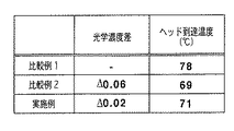
図5は、本実施形態において、A0サイズで100%の記録率の画像を、4パスのマルチパス記録方法で記録した場合の記録ヘッドの到達温度および待機制御を実施して形成された画像領域と待機制御を実施せずに記録された領域との光学濃度差を示す図である。また図5には、本実施形態との比較例として、ヘッド温度に関わらず待機制御を実施しない場合と(比較例1)、ヘッド温度が閾値温度66℃を超えた場合に、直後の記録走査前にのみ1秒の待機時間を設けた場合(比較例2)の結果も併記してある。 FIG. 5 shows an image area formed by controlling the reach temperature of the recording head and standby control when an image of A0 size and 100% recording rate is recorded by the 4-pass multi-pass recording method in this embodiment. FIG. 6 is a diagram showing an optical density difference between a recording area and a recording area without performing standby control. Also, in FIG. 5, as a comparative example with the present embodiment, the recording scan immediately after the case where the standby control is not performed regardless of the head temperature (Comparative Example 1) and the head temperature exceeds the threshold temperature 66 ° C. The result when the standby time of 1 second is provided only before (Comparative Example 2) is also shown.
図5において、比較例1では待機制御が実施されないため、記録された画像に濃度ムラは発生しないが、記録動作の進行に伴ってヘッド温度は上昇しつづけ、最終的に78℃にまで到達した。一方、比較例2では、ヘッド温度が66℃を超えた場合に、直後の走査前にのみ1秒の待機時間を設けるため記録ヘッドの過昇温は抑制され、記録ヘッドの温度は69℃程度で飽和した。しかし、待機制御を行って記録した領域と、待機制御が行われずに記録された隣接領域との間には光学濃度差が0.06程度発生した。この光学濃度差により、画像には目視によって濃度ムラが認識された。 In FIG. 5, since the standby control is not performed in Comparative Example 1, density unevenness does not occur in the recorded image, but the head temperature continues to rise as the recording operation proceeds and finally reaches 78 ° C. . On the other hand, in Comparative Example 2, when the head temperature exceeds 66 ° C., a standby time of 1 second is provided only before the next scan, so that the overheating of the recording head is suppressed and the temperature of the recording head is about 69 ° C. Saturated at. However, an optical density difference of about 0.06 occurred between the area recorded by performing the standby control and the adjacent area recorded without performing the standby control. Due to this optical density difference, density unevenness was visually recognized in the image.
これに対し、本実施形態における記録装置では、待機時間が0.3秒に設定されているため、前述の待機制御を実施して形成された領域と、待機制御を実施せずに形成された隣接領域との光学濃度差は、0.02程度しか発生しなかった。この0.02の光学濃度差は、目視によっては認識されないレベルであり、この光学濃度差による画像品質の低下は認められなかった。 On the other hand, in the recording apparatus according to the present embodiment, since the standby time is set to 0.3 seconds, the area formed by performing the above-described standby control and formed without performing the standby control. The optical density difference from the adjacent region occurred only about 0.02. This optical density difference of 0.02 is a level that cannot be recognized by visual observation, and no deterioration in image quality due to this optical density difference was observed.
また、ダイオードセンサ50によって検出された温度が、閾値温度66℃を越えた場合にも、図4に示したテーブルに従って所定回数の待機制御が実施されるため、ヘッド温度を一定温度以下に保つことができる。すなわち、ヘッド温度が66℃〜70℃に到達した時点で待機時間を伴う記録走査が4回繰り返される。また、ヘッド温度が71℃〜75℃に到達した場合には待機時間を伴う記録走査が6回、ヘッド温度が76℃以上になった場合には待機時間を伴う記録走査が8回の実施される。この制御により、検出されたヘッド温度が、前記3段階の温度範囲のいずれにあっても、記録ヘッドの温度は71℃程度で飽和した。従って、本実施形態によれば、待機制御を実施しない比較例1に比べて大幅に記録ヘッドの温度を低減させることができ、不吐出の発生を低減することができた。また、ヘッドの温度が低減されるため、蓄熱に起因する記録ヘッドの破損も軽減することができる。 Further, even when the temperature detected by the diode sensor 50 exceeds the threshold temperature 66 ° C., the head temperature is kept below a certain temperature because the standby control is performed a predetermined number of times according to the table shown in FIG. Can do. That is, when the head temperature reaches 66 ° C. to 70 ° C., the recording scan with the standby time is repeated four times. Further, when the head temperature reaches 71 ° C. to 75 ° C., the recording scan with the standby time is performed six times, and when the head temperature becomes 76 ° C. or more, the recording scan with the standby time is performed eight times. The With this control, the temperature of the recording head was saturated at about 71 ° C., regardless of the detected head temperature in any of the three temperature ranges. Therefore, according to the present embodiment, the temperature of the recording head can be greatly reduced as compared with Comparative Example 1 in which standby control is not performed, and the occurrence of non-ejection can be reduced. Further, since the temperature of the head is reduced, damage to the recording head due to heat storage can be reduced.
以上説明したように本実施形態におけるインクジェット記録装置では、各記録走査の度に記録ヘッドの温度THを検出し、ヘッド温度THが閾値温度TWを超えた場合には、それ以降に行うべき複数の主走査において待機制御を実施する。この際、待機制御を実施すべき走査回数(設定走査回数)はヘッド温度THに見合った回数に設定される。すなわち、ヘッド温度THが高温の場合には設定走査回数を増し、記録ヘッド5が放熱される状態となる回数が増加する。これにより、記録ヘッドの過昇温を抑制することが可能になり、記録ヘッドの熱による破損や不吐出の発生などを軽減することができる。
As described above, in the ink jet recording apparatus according to the present embodiment, the temperature TH of the recording head is detected at each recording scan, and when the head temperature TH exceeds the threshold temperature TW, a plurality of processes to be performed thereafter are performed. Standby control is performed in main scanning. At this time, the number of scans (set number of scans) at which standby control is to be performed is set to a number commensurate with the head temperature TH. That is, when the head temperature TH is high, the set number of scans is increased, and the number of times that the
また、各記録走査間に設定される待機時間は、その待機制御を実施した後に記録された画像領域と待機制御を実施せずに記録された隣接領域との色差が発生しないような時間に設定される。このため、画像中に濃度ムラや色相ムラが認識されないようにすることが可能となる。このように、本実施形態では、装置の信頼性向上と記録画像の高品質化とを両立することが可能になる。 In addition, the standby time set between recording scans is set so that a color difference between the image area recorded after the standby control is performed and the adjacent area recorded without performing the standby control does not occur. Is done. For this reason, it becomes possible to prevent density unevenness and hue unevenness from being recognized in the image. As described above, according to the present embodiment, it is possible to improve both the reliability of the apparatus and the quality of the recorded image.
なお、本実施形態においては、待機時間を0.3秒に設定した。しかし、濃度や色相に関係する条件、例えば、使用する記録媒体の種類、記録モード、あるいはインク吐出数などの各種記録条件などに応じて、待機時間をより適正な時間に変更するよう制御することも可能である。これによれば、濃度ムラや色相ムラの発生をより低減でき、画像品質を一層高めることが可能になる。 In this embodiment, the standby time is set to 0.3 seconds. However, control is performed to change the standby time to a more appropriate time according to conditions related to density and hue, for example, various recording conditions such as the type of recording medium used, the recording mode, or the number of ink ejections. Is also possible. According to this, the occurrence of density unevenness and hue unevenness can be further reduced, and the image quality can be further improved.
また、本実施形態においては、待機フラグがONされている期間中はヘッド温度THを取得しないような制御とした。しかし待機フラグがONされている期間中もヘッド温度THを取得して、以降の待機制御の実施回数を変更したり、取得後に再び設定走査回数nをリセットして待機制御をやり直したりすることも可能である。このように、ヘッド温度の変化に応じて設定走査回数を随時、変更するようにすれば、より精緻なヘッド温制御を行うことが可能になり、過昇温の抑制効果は一層向上する。 In the present embodiment, control is performed so that the head temperature TH is not acquired during the period when the standby flag is ON. However, it is also possible to acquire the head temperature TH during the period when the standby flag is ON and change the number of subsequent standby controls, or reset the set number of scans n after the acquisition and restart the standby control. Is possible. As described above, if the set number of scans is changed as needed according to the change in the head temperature, more precise head temperature control can be performed, and the effect of suppressing the excessive temperature rise is further improved.
さらに、本実施形態においては、設定走査回数nがヘッド温度に応じて複数段階(図4では3段階)に変更される制御を行うものとした。しかし、本発明はこれに限定されるものではなく、ヘッド温度THが閾値温度を超えた場合に、そのヘッド温度に拘わりなく常に一定回数の走査に対して待機制御を実施することも可能である。さらに、待機制御を行う走査回数(設定走査回数)nを、各種記録条件に応じて待最適な設定値に変更するような制御を行うことにより、記録ヘッドの過昇温を、より確実に抑制することができる。 Further, in the present embodiment, control is performed in which the set number of scans n is changed in a plurality of stages (three stages in FIG. 4) according to the head temperature. However, the present invention is not limited to this, and when the head temperature TH exceeds the threshold temperature, it is also possible to always perform standby control for a fixed number of scans regardless of the head temperature. . Furthermore, by controlling the number of scans (set number of scans) n for standby control to a set value that is optimal for standby according to various printing conditions, the overheating of the print head is more reliably suppressed. can do.
またさらに、本実施形態では、ヘッド温度THが閾値温度を超えた場合、ヘッド温度THに応じて待機制御を行う走査回数nを複数段階(3段階)に変更する構成としている。しかし、ヘッド温度THが閾値温度を超えた場合に待機制御を行う走査回数を予め定めておき、ヘッド温度THの温度に応じて、予め定められた回数分の走査それぞれの待機時間を変更するように構成することも出来る。 Furthermore, in this embodiment, when the head temperature TH exceeds the threshold temperature, the number of scans n for performing standby control according to the head temperature TH is changed to a plurality of stages (three stages). However, the number of scans for performing standby control when the head temperature TH exceeds the threshold temperature is determined in advance, and the standby time for each predetermined number of scans is changed according to the temperature of the head temperature TH. It can also be configured.
また、待機制御を行う走査は、連続した走査である必要はない。本実施形態の場合、ヘッド温度が66℃〜70℃場合、第1回走査から第4回走査で待機制御を実施しているが、例えば、第1回走査、第3回走査、第5回走査、第7回走査のように、1走査おきに待機制御を実施するようにしても構わない。 Further, the scanning for performing the standby control does not have to be continuous scanning. In this embodiment, when the head temperature is 66 ° C. to 70 ° C., standby control is performed from the first scan to the fourth scan. For example, the first scan, the third scan, and the fifth scan are performed. The standby control may be performed every other scan as in the scan and the seventh scan.
(第2の実施形態)
次に、本発明の第2の実施形態を説明する。
この第2の実施形態は、ヘッド温度THおよび待機制御を実施する走査の回数(走査回数)nに応じて、待機制御中の各走査前に設定する待機時間を変化させることを特徴とするものであり、その他の点は上記第1の実施形態と同様である。従って、この第2の実施形態におけるインクジェット記録装置においても図1および図2に示す構成を有するものとなっている。
(Second Embodiment)
Next, a second embodiment of the present invention will be described.
The second embodiment is characterized in that the standby time set before each scan during standby control is changed in accordance with the head temperature TH and the number of scans (number of scans) n in which standby control is performed. Other points are the same as those of the first embodiment. Therefore, the ink jet recording apparatus according to the second embodiment also has the configuration shown in FIGS.
図6は、本実施形態のインクジェット記録装置において待機時間を設定するために用いられるテーブルを示す図である。この第2の実施形態におけるインクジェット記録装置では、ヘッド温度THに応じて、走査開始前に設ける待機時間および待機制御を実施する走査回数(設定走査回数)が定められるようになっている。例えば、ヘッド温度が66℃〜70℃の範囲(第1の段階)にある場合には、走査回数は6回に制御され、ヘッド温度が71℃〜75℃の範囲(第2の段階)および76℃以上(第3の段階)にある場合には、走査回数は8回に制御されるようになっている。 FIG. 6 is a diagram showing a table used for setting the standby time in the ink jet recording apparatus according to the present embodiment. In the ink jet recording apparatus according to the second embodiment, the standby time provided before the start of scanning and the number of scans for performing standby control (set number of scans) are determined according to the head temperature TH. For example, when the head temperature is in the range of 66 ° C. to 70 ° C. (first stage), the number of scans is controlled to 6 times, and the head temperature is in the range of 71 ° C. to 75 ° C. (second stage) and When the temperature is 76 ° C. or higher (third stage), the number of scans is controlled to 8 times.
さらに、この第2の実施形態では、待機制御を行うべき走査が順次実施されて行くに従って、待機時間が変化するような制御を行う。すなわち、待機制御の対象となっている走査において、走査回数が少ない段階では待機時間は比較的短い時間に設定され、走査回数がある一定回数に達すると待機時間が一旦長くなり、さらに走査回数が増すと再び待機時間が減少する。例えば、ヘッド温度が第1の段階(66℃〜70℃)にある場合、第1回目および第2回目の走査に対して設定される待機時間は0.1秒となる。さらに、第3回目および第4回目の走査に対して設定される待機時間は0.3秒となり、その後、第5回目および第6回目の走査に対して設定される待機時間は、再び0.1秒に短縮されるように制御される。 Furthermore, in the second embodiment, control is performed such that the standby time changes as the scans for which standby control is to be performed are sequentially performed. That is, in the scanning that is subject to standby control, when the number of scans is small, the standby time is set to a relatively short time. When the number of scans reaches a certain number of times, the standby time is once longer, and the number of scans is further increased. As it increases, the waiting time decreases again. For example, when the head temperature is in the first stage (66 ° C. to 70 ° C.), the standby time set for the first and second scans is 0.1 seconds. Further, the standby time set for the third and fourth scans is 0.3 seconds, and thereafter, the standby time set for the fifth and sixth scans is again set to 0. 0. It is controlled to be shortened to 1 second.
このような、待機時間の設定方法を採ることにより、複数回走査させることによって形成される各領域間の濃度ムラや色相ムラの発生をより効果的に低減することができる。以下、その理由を説明する。なお、以下の説明では、記録媒体上の同一領域に対して2回の記録走査で画像を完成させる、2パスのマルチパス記録方法を行う場合を例に採り説明する。 By adopting such a standby time setting method, it is possible to more effectively reduce the occurrence of density unevenness and hue unevenness between regions formed by scanning a plurality of times. The reason will be described below. In the following description, a case of performing a two-pass multi-pass printing method in which an image is completed by two printing scans on the same area on the printing medium will be described as an example.
2パスのマルチパス記録方法では、例えば、第1回目と第2回目の記録走査によって一つの領域が完成する。同様に、第2回目と第3回目、第3回目と第4回目、第4回目と第5回目、第5回目と第6回目、の各2回ずつ行われる記録走査によって他の4個の領域の画像が順次形成される。この場合、待機時間を介在しない2つの記録走査によって形成される領域と、これに隣接し、かつ待機時間が介在する2つの記録走査によって形成される領域とでは、各領域の形成時に設けられる待機時間の差は、僅かな時間(0.1秒)となる。 In the 2-pass multi-pass printing method, for example, one region is completed by the first and second printing scans. Similarly, the other four print scans are performed twice each of the second and third times, the third and fourth times, the fourth and fifth times, and the fifth and sixth times. Area images are sequentially formed. In this case, an area formed by two recording scans that do not involve standby time and an area that is adjacent to the area that is formed by two recording scans that interpose standby time are provided at the time of forming each area. The difference in time is a short time (0.1 second).
すなわち、上記の待機時間が介在しない2つの記録走査によって形成される領域としては、第1回目の記録走査の1回前の記録走査と2回前の記録走査とで形成された領域(領域A)と、第6回目とその次の記録走査とで形成される領域(領域H)とがある。また、これらの領域に隣接し、かつ待機時間が介在する2つの記録走査によって形成される領域としては、第1回目の記録走査とその直前の記録走査とで形成される領域(領域B)と、第5回目と第6回目の記録走査で形成される領域(領域G)とがある。そして、前記の領域Aと領域Bが互いに隣接し、領域Gと領域Hが互いに隣接する。ここで、領域Aを形成する2つの記録走査間の待機時間は0であり、領域Bを形成する2つの記録走査間の待機時間0.1秒であり、両領域の形成において設けられる待機時間の差は0.1秒である。同様に領域Gと領域Hについても待機時間の差は0.1秒となる。従って、領域Aと領域Bの間、および領域Gと領域Hの間には、殆ど色相や濃度において差が生じることはなく、目視で認識できるような濃度ムラおよび色相ムラが生じることはない。 That is, the area formed by the two recording scans without the waiting time is an area (area A) formed by the first and second recording scans of the first recording scan. ) And a region (region H) formed by the sixth time and the next recording scan. In addition, as an area formed by two recording scans adjacent to these areas and having a standby time, an area (area B) formed by the first recording scan and the immediately preceding recording scan is used. There are regions (regions G) formed by the fifth and sixth recording scans. The region A and the region B are adjacent to each other, and the region G and the region H are adjacent to each other. Here, the waiting time between the two recording scans forming the region A is 0, the waiting time between the two recording scans forming the region B is 0.1 second, and the waiting time provided in forming both regions The difference is 0.1 seconds. Similarly, the difference in waiting time between the region G and the region H is 0.1 second. Therefore, there is almost no difference in hue and density between the region A and the region B and between the region G and the region H, and density unevenness and hue unevenness that can be visually recognized do not occur.
さらに、待機時間が介在する2つの記録走査によって形成される領域についても、隣接する領域間には大きな待機時間の差が生じない。例えば、第1回目と第2回目の記録走査で形成される領域(領域C)には、第2回目と第3回目の記録走査で形成される領域(領域D)が隣接する。また、第3回目と第4回目の記録走査で形成される領域(領域E)には、第4回目と第5回目の記録走査で形成される領域(領域F)が隣接する。ここで、領域Cを形成する2つの記録走査間の待機時間は0.1秒であり、これに隣接する領域Dを形成する2つの記録走査間の待機時間は0.3秒である。よって、両領域の形成において設けられる待機時間の差は僅かに0.2秒となる。同様に、領域Eの待機時間と領域Fの待機時間の差は、0.2秒となる。このように、待機時間が介在する2つの記録走査によって形成される各領域についても、隣接する領域の待機時間の差は僅かな時間となるため、色相や濃度の差は殆ど発生せず、目視で認識できるような濃度ムラや色相ムラが生じることはない。同様に、ヘッド温度THが第2の段階(71℃〜75℃)である場合、および第3の段階(76℃以上)である場合のいずれにおいても、隣接する領域間で待機時間に大きな差が生じないように制御されている。このため、各記録走査によって形成される画像の隣接領域において画像の濃度ムラ、色相ムラなどの弊害が発生するのを極力低減することができる。 Further, even in an area formed by two printing scans in which the standby time is interposed, a large difference in standby time does not occur between adjacent areas. For example, a region (region D) formed by the second and third recording scans is adjacent to a region (region C) formed by the first and second recording scans. Further, the region (region F) formed by the fourth and fifth recording scans is adjacent to the region (region E) formed by the third and fourth recording scans. Here, the waiting time between two recording scans forming the region C is 0.1 second, and the waiting time between two recording scans forming the region D adjacent thereto is 0.3 second. Therefore, the difference between the standby times provided in the formation of both regions is only 0.2 seconds. Similarly, the difference between the standby time of area E and the standby time of area F is 0.2 seconds. As described above, also in each area formed by two printing scans in which the standby time is interposed, the difference in the standby time between the adjacent areas is small, so that there is almost no difference in hue and density, and visual inspection is performed. No density unevenness or hue unevenness that can be recognized by. Similarly, whether the head temperature TH is the second stage (71 ° C. to 75 ° C.) or the third stage (76 ° C. or higher), there is a large difference in standby time between adjacent regions. It is controlled so as not to occur. For this reason, it is possible to reduce the occurrence of adverse effects such as image density unevenness and hue unevenness in an adjacent region of an image formed by each recording scan as much as possible.
また、この第2の実施形態では、ヘッド温度THの段階が高まるにつれて、待機制御の実施回数が制御されると共に、各待機時間は少しずつ長くなるように制御されている。例えばヘッド温度THが第1の段階(66℃〜70℃)であるときには、第1回目および第2回目の各記録走査前に設けられる待機時間は0.1秒となる。しかし、ヘッド温度THが第2の段階(71℃〜75℃)であるときには、待機時間は0.2秒に、ヘッド温度が76℃以上であるときには待機時間は0.3秒に、それぞれ設定されている。このように、この第2の実施形態では、ヘッド温度THの上昇に伴って、待機時間を増大させて放熱時間を段階的に増加させることにより、ヘッドの過昇温を抑制することが可能になる。なお、以上の説明では、2パス記録を行う場合について述べたが、3回以上の走査によって一つの領域を形成する場合にも、本実施形態における待機時間の設定方法を用いることは可能であり、記録ヘッドの過昇温の低減および濃度ムラ、色相ムラの低減に有効である。 In the second embodiment, as the head temperature TH increases, the number of standby control operations is controlled, and each standby time is controlled to be slightly longer. For example, when the head temperature TH is in the first stage (66 ° C. to 70 ° C.), the standby time provided before the first and second print scans is 0.1 second. However, when the head temperature TH is in the second stage (71 ° C. to 75 ° C.), the standby time is set to 0.2 seconds, and when the head temperature is 76 ° C. or higher, the standby time is set to 0.3 seconds. Has been. Thus, in the second embodiment, as the head temperature TH rises, the standby time is increased and the heat dissipation time is increased stepwise, thereby suppressing the excessive temperature rise of the head. Become. In the above description, the case of performing two-pass printing has been described. However, the standby time setting method in the present embodiment can also be used when one region is formed by three or more scans. It is effective for reducing the excessive temperature rise of the recording head and reducing density unevenness and hue unevenness.
以上のように、この第2の実施形態では、ヘッド温度および設定走査回数に応じて、待機制御を実施すべき各走査の開始前に設定する待機時間を変化させると共に、待機制御実施回数が進むにつれて設定待機時間を段階的に変化させるようになっている。このため、各走査における隣接領域の色相および濃度を段階的に変化させることが可能となり、待機時間の差に伴って生じる濃度ムラや色相ムラを視認されにくい程度に抑えることが可能になる。さらに、ヘッド温度が上昇した場合に設定待機回数が増えると共に、待機時間も長くなるよう制御することで、記録ヘッドの過昇温やそれに伴う弊害の発生を極力低減することが可能になる。 As described above, in the second embodiment, the standby time set before the start of each scan for which standby control is to be performed is changed according to the head temperature and the set number of scans, and the standby control execution count is advanced. As a result, the set waiting time is changed step by step. For this reason, it is possible to change the hue and density of adjacent regions in each scanning step by step, and it is possible to suppress density unevenness and hue unevenness caused by the difference in standby time to a level where it is difficult to be visually recognized. Further, when the head temperature rises, the set number of standby times is increased and the standby time is also lengthened, so that it is possible to reduce the excessive temperature rise of the print head and the accompanying adverse effects as much as possible.
なお、この第2の実施形態においては待機制御の対象となる記録走査に対して設定される待機時間を一旦段階的に長くし、その後段階的に短くなるように制御したが、待機時間の設定方法は、これに限定されるものではない。すなわち、待機制御は、前後の記録走査において設定される待機時間の差がなるべく少なくなるように行えばよく、連続的に待機時間を変化させることも可能である。さらに、待機時間を段階的あるいは連続的に長くした後に、段階的あるいは連続的に短くするような制御を繰り返してもよく、要は、複数回の走査によって順次形成されて行く領域の中で、隣接する領域間で生じる色差が段階的に変化するような時間設定を行えばよい。 In the second embodiment, the standby time set for the recording scan to be subjected to standby control is increased temporarily in steps and then reduced in stages. The method is not limited to this. That is, the standby control may be performed so that the difference between the standby times set in the preceding and subsequent print scans is as small as possible, and the standby time can be continuously changed. Furthermore, after the standby time is lengthened stepwise or continuously, the control of shortening stepwise or continuously may be repeated. In short, in the region formed sequentially by a plurality of scans, Time setting may be performed so that the color difference generated between adjacent regions changes stepwise.
また、この第2の実施形態においてはヘッド温度が閾値温度を超えた場合に、待機時間の設定を2段階または3段階に変更するような制御を行う場合を例に採り説明した。しかし、本発明はこれに限定されるものではなく、閾値温度を超えた場合に、一つの待機時間のみを設定することも可能である。また、ヘッド温度に応じてより多くの段階に分けて待機時間を変化させるような制御を行うことも可能である。さらに、上記実施形態では、一つの閾値温度を越えた場合にのみ待機制御を行うようにしたが、複数の閾値を設定し、各閾値によって設定される温度範囲毎に待機時間を設定しても良い。さらに、閾値を設定せず、各ヘッド温度に応じて待機時間を随時変化させることも可能であり、要は、ヘッド温度に応じた最適な待機時間を設定すれば良い。 In the second embodiment, the case where control is performed to change the setting of the standby time to two steps or three steps when the head temperature exceeds the threshold temperature has been described as an example. However, the present invention is not limited to this, and it is possible to set only one waiting time when the threshold temperature is exceeded. It is also possible to perform control such that the standby time is changed in more stages according to the head temperature. Further, in the above embodiment, standby control is performed only when a single threshold temperature is exceeded, but a plurality of thresholds may be set, and a standby time may be set for each temperature range set by each threshold. good. Furthermore, it is possible to change the standby time at any time according to each head temperature without setting a threshold value. In short, an optimal standby time may be set according to the head temperature.
(第3の実施形態)
次に、本発明の第3の実施形態を図7および図8を参照して説明する。
記録ヘッドの構造や記録ヘッドの単位時間当たりの吐出数などによっては、ヘッド温度が急激に高温に達することがある。このような場合、上記各実施形態のように短時間の待機時間を複数の走査の前に設ける待機制御のみでは、ヘッド温度が十分に低下しない、あるいはヘッド温度が上昇してしまうといった現象が生じることがある。このような現象が生じた場合、記録ヘッドに不吐出が発生し画像品質が著しく劣化する虞がある。そこで、この第3の実施形態では、記録ヘッドの温度が非常に高い温度に達したとき、1回の記録走査の前に、長い待機時間(例えば1秒)を設けて、急速にヘッド温度THを低下させることにより、不吐出の発生を回避するようになっている。なお、この第3の実施形態におけるインクジェット記録装置も、図1および図2に示す構成を備える。
(Third embodiment)
Next, a third embodiment of the present invention will be described with reference to FIGS.
Depending on the structure of the recording head and the number of ejections per unit time of the recording head, the head temperature may suddenly reach a high temperature. In such a case, the head temperature does not sufficiently decrease or the head temperature rises only by standby control in which a short standby time is provided before a plurality of scans as in the above embodiments. Sometimes. When such a phenomenon occurs, non-ejection may occur in the recording head, and image quality may be significantly degraded. Therefore, in the third embodiment, when the temperature of the recording head reaches a very high temperature, a long standby time (for example, 1 second) is provided before one recording scan, and the head temperature TH is rapidly increased. The occurrence of non-ejection is avoided by reducing the above. The ink jet recording apparatus according to the third embodiment also has the configuration shown in FIGS.
図7は、この第3の実施形態において1ページ分の画像を記録する際にMPU21が実行する一連の工程を説明するためのフローチャートである。
図7に示すように、この第3の実施形態では、図3のフローチャートに示す制御に対して、ステップS303a、S308aの工程を追加して実施する。すなわち、ヘッド温度THを取得した後、そのヘッド温度が上記各実施形態において設定されている閾値(ここでは、TW2と記す)を大きく上回る温度の閾値TW1(例えば、80度)を超えたか否かをステップS303aにおいて判断する。ヘッド温度TWが閾値TW1を超えていないと判断された場合には、さらにヘッド温度THが閾値TW2を超えているか否かを判断する。この判断の結果に基づく制御は、上記第1の実施形態と同様に行われる。すなわち、ヘッド温度THが閾値TW2以下である場合にステップS306において記録ヘッドによる主走査を行う。そして、ヘッド温度THが閾値TW2を超える場合には、ステップS305において図8に示すテーブルに応じたヘッド温度に対応する待機時間(0.3秒)と待機回数を設定し、その設定に従って主走査を行う(ステップS306)。
FIG. 7 is a flowchart for explaining a series of steps executed by the
As shown in FIG. 7, in the third embodiment, steps S303a and S308a are added to the control shown in the flowchart of FIG. That is, after acquiring the head temperature TH, whether or not the head temperature has exceeded a threshold value TW1 (for example, 80 degrees) that is much higher than the threshold value (referred to as TW2 here) set in each of the above embodiments. Is determined in step S303a. If it is determined that the head temperature TW does not exceed the threshold TW1, it is further determined whether or not the head temperature TH exceeds the threshold TW2. Control based on the result of this determination is performed in the same manner as in the first embodiment. That is, when the head temperature TH is equal to or lower than the threshold value TW2, main scanning by the recording head is performed in step S306. When the head temperature TH exceeds a threshold value TW2, the times waited waiting time (0.3 seconds) corresponding to the head temperature according to the table shown in FIG. 8 set in step S305, the main scanning according to the setting Is performed (step S306).
一方、ステップS303aの判断において、ヘッド温度TWが閾値TW1を超えていた場合には、ステップS305へ移行する。ステップS305では、図8に示すテーブルに従って、待機回数を1回に設定し、次に行われる1回の走査の開始を1秒間待機させる。なお、図8に示すテーブルは、66℃〜70℃、71℃〜75℃、76℃〜79℃、80℃以上の4段階の温度に応じて、4回、6回、8回、1回の異なる設定走査回数がそれぞれ設定されている。また、66℃〜79℃の範囲に設定される3段階においては、各走査前に設けられる待機時間が一律に0.3secに設定されている。但し、80℃以上のヘッド温THについては、待機時間(1秒)が設定されている。 On the other hand, if it is determined in step S303a that the head temperature TW exceeds the threshold value TW1, the process proceeds to step S305. In step S305, the number of standby times is set to one according to the table shown in FIG. 8, and the start of the next one scan is waited for one second. In addition, the table shown in FIG. 8 is 4 times, 6 times, 8 times, 1 time according to the temperature of 4 steps | paragraphs of 66 to 70 degreeC, 71 to 75 degreeC, 76 to 79 degreeC, and 80 degreeC or more. The different set scanning times are set. In the three stages set in the range of 66 ° C. to 79 ° C., the standby time provided before each scan is uniformly set to 0.3 sec. However, a standby time (1 second) is set for a head temperature TH of 80 ° C. or higher.
主走査が行われた後、ステップS307では、ステップ記録動作が終了したか否かの判断を行う。記録動作が終了していない場合には、ヘッド温度THが閾値T1(80℃)イを超えるか否かを判断する。ここで、ヘッド温度THが閾値T1を超えていると判断された場合には、ステップS305へ移行し、待機時間を1秒に、待機回数を1回にそれぞれ設定する。そして、待機時間1秒が経過した後、ステップS306で主走査を行う。この後、ステップS307で記録動作がいまだ完了していないと判断された場合には、ステップS308aで再びヘッド温度THが閾値TW1を超えているか否かを判断し、超えていなければ、ステップS308でフラッグがONであるか否かを判断する。フラグがONであれば、ステップS305において設定された第n回の走査が終了したか否かの判断を行う(S309)。前回の走査の後、ヘッド温度THがTW1を超えていた場合には、ステップS305において走査回数が1回に設定されており、この走査は既にステップS306において実行されている。従って、この場合には、ステップS309の判断の後、ステップS310へと移行し、ここでフラッグがOFFされる。この後、ステップS302へ移行し、再びヘッド温度THの取得動作を行う。 After the main scanning is performed, in step S307, it is determined whether or not the step recording operation is finished. If the recording operation has not ended, it is determined whether or not the head temperature TH exceeds a threshold value T1 (80 ° C.) b. If it is determined that the head temperature TH exceeds the threshold value T1, the process proceeds to step S305, where the standby time is set to 1 second, and the standby count is set to 1 time. After the waiting time of 1 second has elapsed, main scanning is performed in step S306. Thereafter, if it is determined in step S307 that the recording operation has not yet been completed, it is determined again in step S308a whether or not the head temperature TH exceeds the threshold value TW1, and if not, in step S308. It is determined whether or not the flag is ON. If the flag is ON, it is determined whether or not the nth scan set in step S305 has ended (S309). If the head temperature TH has exceeded TW1 after the previous scan, the number of scans is set to 1 in step S305, and this scan has already been performed in step S306. Therefore, in this case, after the determination in step S309, the process proceeds to step S310, where the flag is turned OFF. Thereafter, the process proceeds to step S302, and the operation for acquiring the head temperature TH is performed again.
上記のようにこの第3の実施形態では、ヘッド温度THが、閾値TW2より高く、かつ閾値TW1以下である場合には、上記第1の実施形態と同様に、そのヘッド温度に応じて定められる複数回の走査では、0.3秒の待機時間が設けられる。しかし、ヘッド温度THが閾値TW1より高い場合には、1秒間という長い待機時間が設けられるため、この間に記録ヘッドの温度を十分に低下させることができ、記録ヘッドの過度な温度上昇に起因する不吐出の発生を確実に抑えることが可能になる。 As described above, in the third embodiment, when the head temperature TH is higher than the threshold value TW2 and lower than or equal to the threshold value TW1, it is determined according to the head temperature as in the first embodiment. In the multiple scans, a waiting time of 0.3 seconds is provided. However, when the head temperature TH is higher than the threshold value TW1, since a long standby time of 1 second is provided, the temperature of the recording head can be sufficiently lowered during this time, which is caused by an excessive temperature rise of the recording head. The occurrence of non-ejection can be reliably suppressed.
なお、上記第3の実施形態では、ヘッド温度THが閾値TW2以下の場合には、上記第1の実施形態と同様に、待機制御を行うべき各走査に対して一律に0.3秒の待機時間を設定するものとなっている。しかしこの第3の実施形態においても、上記第2の実施形態と同様に、待機制御を実行すべき各走査に対する待機時間を、走査の進行に伴って変化させるようにすることも可能である。 In the third embodiment, when the head temperature TH is equal to or lower than the threshold value TW2, similarly to the first embodiment, a standby of 0.3 seconds is uniformly performed for each scan to be subjected to standby control. Time is to be set. However, also in the third embodiment, similarly to the second embodiment, it is possible to change the standby time for each scan for which standby control is to be performed as the scan progresses.
また、この第3の実施形態においても、待機フラグがONされている期間中はヘッド温度THを取得しないような制御とした。しかし、待機フラグがONされている期間中もヘッド温度THを取得して、以降の待機制御の実施回数を変更したり、取得後に再び設定走査回数nをリセットして待機制御をやり直したりすることも可能である。 Also in the third embodiment, control is performed such that the head temperature TH is not acquired during the period when the standby flag is ON. However, the head temperature TH is acquired even during the period when the standby flag is ON, and the number of subsequent standby control executions is changed, or after the acquisition, the set scanning number n is reset again and the standby control is performed again. Is also possible.
(他の実施形態)
上記各実施形態では、記録ヘッドのインク吐出を往路と復路の双方において行う双方向記録を行う場合について説明したが、記録ヘッドからのインク吐出を往路または復路のいずれか一方でのみ行う、いわゆる一方向記録にも本発明は適用可能である。すなわち、一方向記録の場合には、インク吐出を実施しない走査(戻し走査)においては、インク吐出を実施する走査に比べて高速にキャリッジを移動させるため、戻し走査期間を介しても記録ヘッドの温度が低下しない場合が多い。従って、一方向記録においても、本発明のような待機制御を行うことは上記実施形態と同様に有効である。
(Other embodiments)
In each of the embodiments described above, the case where bidirectional printing is performed in which the ink ejection of the recording head is performed in both the forward path and the backward path has been described. However, the ink ejection from the recording head is performed only in either the forward path or the backward path. The present invention can also be applied to direction recording. That is, in the case of unidirectional printing, in the scan not performing ink ejection (return scan), the carriage is moved at a higher speed than in the scan performing ink ejection. In many cases, the temperature does not decrease. Therefore, even in one-way recording, it is effective to perform standby control as in the present invention as in the above embodiment.
上記各実施形態では、記録ヘッドの各ノズル内に設けた電気熱変換素子から発生する熱エネルギによってノズル内の液体に気泡を発生させ、その気泡発生時の圧力によってインクを吐出させるインクジェット記録装置を説明した。しかし、本発明は、電気熱変換素子を使用するものに限らず、ピエゾなどの電気機械変換素子を各ノズル内に設けた記録ヘッドで記録を行う記録装置にも適用可能である。 In each of the above embodiments, an ink jet recording apparatus that generates bubbles in the liquid in the nozzles by the thermal energy generated from the electrothermal conversion elements provided in the nozzles of the recording head and discharges ink by the pressure at the time of the bubble generation is provided. explained. However, the present invention is not limited to the one using an electrothermal conversion element, and can also be applied to a recording apparatus that performs recording with a recording head in which an electromechanical conversion element such as a piezo is provided in each nozzle.
上記各実施形態では、記録ヘッドと記録媒体との相対的な走査を行う形態として、記録ヘッドを往復走査させる例を説明したが、記録ヘッドに対して記録媒体往復移動させて記録を行う形態にも本発明が適用可能であることは言うまでもない。 In each of the above-described embodiments, an example in which the recording head is reciprocally scanned has been described as a form for performing relative scanning between the recording head and the recording medium. However, the recording head is reciprocated with respect to the recording head to perform recording. Needless to say, the present invention is applicable.
1 搬送モータ
2 プラテンローラ
3a、3b ガイドシャフト
4 キャリッジ
5 記録ヘッド
6 キャリッジモータ
7 搬送モータ
M 記録媒体
H ホスト装置
20 インターフェース
21 MPU
22 ROM
23 DRAM
24 ゲートアレイ
25,26 モータドライバ
27 ヘッドドライバ
50 ダイオードセンサ
DESCRIPTION OF
22 ROM
23 DRAM
24
Claims (11)
前記記録ヘッドを記録媒体上の同一領域に対して相対的に複数回走査させる走査手段と、
前記記録ヘッドの温度を検出する検出手段と、
前記検出手段により検出された温度に基づいて、前記記録ヘッドの走査開始前に待機すべき走査の回数と、前記回数分の記録ヘッドの走査それぞれにおける待機時間とを設定する設定手段と、を備え、
前記設定手段は、前記待機時間を、待機制御を実施した後に記録された画像領域と待機制御されずに記録された隣接領域との色差が生じない時間であり、かつ設定された走査回数の待機制御を実施したときに記録ヘッドの過昇温を抑制できる時間となるように設定することを特徴とするインクジェット記録装置。 An inkjet recording apparatus that performs recording by discharging ink from a recording head,
Scanning means for scanning the recording head relative to the same area on the recording medium a plurality of times;
Detecting means for detecting the temperature of the recording head;
Setting means for setting, based on the temperature detected by the detection means, the number of scans to be waited before starting the scan of the print head and the waiting time for each scan of the print head for the number of times. ,
The setting means sets the standby time as a time during which no color difference occurs between an image area recorded after performing standby control and an adjacent area recorded without standby control, and waiting for a set number of scans. An ink jet recording apparatus, characterized in that the time is set so that an excessive temperature rise of the recording head can be suppressed when the control is performed .
前記設定手段は、前記検出手段により検出した温度が予め定めた閾値を超えた時点で、前記走査回数の設定を行うことを特徴とする請求項1ないし6のいずれか1項に記載のインクジェット記録装置。 The detection means detects the temperature of the recording head before each scanning of the recording head starts,
The setting means, wherein when the temperature detected by the detecting means exceeds a predetermined threshold value, the ink-jet recording according to any one of claims 1 to 6, characterized in that the setting of the number of scans apparatus.
前記記録ヘッドの温度を検出する工程と、
前記検出された温度に基づいて、前記記録ヘッドの走査開始前に前記記録ヘッドを待機させる走査の回数と、前記回数分の記録ヘッドの走査それぞれにおける待機時間とを設定する設定する工程と、を備え、
前記設定する工程では、前記待機時間を待機制御を実施した後に記録された画像領域と待機制御されずに記録された隣接領域との色差が生じない時間であり、かつ設定された走査回数の待機制御を実施したときに記録ヘッドの過昇温を抑制できる時間となるように設定することを特徴とするインクジェット記録方法。 A recording method for performing recording by ejecting ink from the recording head while scanning a recording head provided with a recording element,
Detecting the temperature of the recording head;
Based on the detected temperature, a step of setting the number of scans to wait for the recording head before the start of scanning of the recording head and a waiting time in each of the scanning of the recording head for the number of times, Prepared ,
In the setting step, the waiting time is a time during which no color difference occurs between the image area recorded after the standby control is performed and the adjacent area recorded without the standby control, and the waiting for the set number of scans. An ink jet recording method, wherein the time is set so that an excessive temperature rise of the recording head can be suppressed when the control is performed .
Priority Applications (1)
| Application Number | Priority Date | Filing Date | Title |
|---|---|---|---|
| JP2008147203A JP5159443B2 (en) | 2007-06-04 | 2008-06-04 | Inkjet recording apparatus and inkjet recording method |
Applications Claiming Priority (3)
| Application Number | Priority Date | Filing Date | Title |
|---|---|---|---|
| JP2007148631 | 2007-06-04 | ||
| JP2007148631 | 2007-06-04 | ||
| JP2008147203A JP5159443B2 (en) | 2007-06-04 | 2008-06-04 | Inkjet recording apparatus and inkjet recording method |
Publications (3)
| Publication Number | Publication Date |
|---|---|
| JP2009012462A JP2009012462A (en) | 2009-01-22 |
| JP2009012462A5 JP2009012462A5 (en) | 2011-07-21 |
| JP5159443B2 true JP5159443B2 (en) | 2013-03-06 |
Family
ID=40087638
Family Applications (1)
| Application Number | Title | Priority Date | Filing Date |
|---|---|---|---|
| JP2008147203A Active JP5159443B2 (en) | 2007-06-04 | 2008-06-04 | Inkjet recording apparatus and inkjet recording method |
Country Status (2)
| Country | Link |
|---|---|
| US (1) | US9010903B2 (en) |
| JP (1) | JP5159443B2 (en) |
Families Citing this family (3)
| Publication number | Priority date | Publication date | Assignee | Title |
|---|---|---|---|---|
| US8439468B2 (en) * | 2008-12-19 | 2013-05-14 | Canon Kabushiki Kaisha | Inkjet print apparatus and inkjet print method |
| JP5871505B2 (en) * | 2011-07-29 | 2016-03-01 | キヤノン株式会社 | Printing apparatus and printing method |
| CN106273441B (en) * | 2015-05-22 | 2018-09-14 | 三纬国际立体列印科技股份有限公司 | The control method and its device of print temperature |
Family Cites Families (9)
| Publication number | Priority date | Publication date | Assignee | Title |
|---|---|---|---|---|
| JP3117854B2 (en) | 1993-11-02 | 2000-12-18 | キヤノン株式会社 | Ink jet apparatus and method of controlling ink jet head for the apparatus |
| JP2001113678A (en) | 1999-10-18 | 2001-04-24 | Copyer Co Ltd | Ink jet recorder |
| JP4280453B2 (en) | 2001-03-21 | 2009-06-17 | キヤノン株式会社 | Recording apparatus and recording head temperature management method |
| US6655772B2 (en) | 2001-03-21 | 2003-12-02 | Canon Kabushiki Kaisha | Printing apparatus and printhead temperature management method |
| JP2005074759A (en) | 2003-08-29 | 2005-03-24 | Canon Inc | Inkjet recording device |
| US7264326B2 (en) * | 2004-05-25 | 2007-09-04 | Brother Kogyo Kabushiki Kaisha | Inkjet printer |
| JP2005349639A (en) | 2004-06-09 | 2005-12-22 | Seiko Epson Corp | Printer and printing method |
| JP2006341570A (en) | 2005-06-10 | 2006-12-21 | Canon Inc | Ink jet recording device and method of ink jet recording |
| JP2007290355A (en) | 2006-03-31 | 2007-11-08 | Canon Inc | Inkjet recording apparatus, and method for controlling inkjet recording head temperature |
-
2008
- 2008-05-28 US US12/128,319 patent/US9010903B2/en active Active
- 2008-06-04 JP JP2008147203A patent/JP5159443B2/en active Active
Also Published As
| Publication number | Publication date |
|---|---|
| JP2009012462A (en) | 2009-01-22 |
| US9010903B2 (en) | 2015-04-21 |
| US20080297552A1 (en) | 2008-12-04 |
Similar Documents
| Publication | Publication Date | Title |
|---|---|---|
| JP4182123B2 (en) | Inkjet recording head and inkjet recording apparatus | |
| JP5409246B2 (en) | Ink jet recording apparatus and recording head temperature control method | |
| JP5105777B2 (en) | Image processing method and inkjet recording apparatus | |
| JP2002166536A (en) | Ink jet recorder | |
| JP2006341570A (en) | Ink jet recording device and method of ink jet recording | |
| US9259921B2 (en) | Ink jet printing apparatus, ink jet printing method, and non-transitory computer-readable storage medium | |
| JP4182122B2 (en) | Ink jet recording apparatus and ink jet recording method | |
| JP5159443B2 (en) | Inkjet recording apparatus and inkjet recording method | |
| JP7451257B2 (en) | Inkjet recording device and inkjet recording method | |
| JP5906042B2 (en) | Inkjet recording apparatus and inkjet recording method | |
| JP6292782B2 (en) | Recording apparatus and recording method | |
| US8474941B2 (en) | Inkjet printing apparatus and inkjet printing method | |
| JP4632416B2 (en) | Inkjet recording apparatus and inkjet recording method | |
| JP5038473B2 (en) | Inkjet recording apparatus and inkjet recording method | |
| JP2010000705A (en) | Inkjet recording device and temperature control method of recording head | |
| JP4280453B2 (en) | Recording apparatus and recording head temperature management method | |
| JP2006076223A (en) | Inkjet recorder, and method and program for controlling its head temperature | |
| JP4537167B2 (en) | Inkjet recording apparatus and recording method | |
| JP3913062B2 (en) | Inkjet recording apparatus and inkjet recording method | |
| JP2004074511A (en) | Inkjet recorder and inkjet recording method | |
| JP4612808B2 (en) | Ink jet recording apparatus and control method in the apparatus | |
| JP2004148680A (en) | Inkjet recording device | |
| JP2005138494A (en) | Inkjet recording device and inkjet recording method | |
| JP2002144539A (en) | Ink jet recording method and recorder | |
| JP2010012653A (en) | Inkjet recorder and recovery processing method of recording head |
Legal Events
| Date | Code | Title | Description |
|---|---|---|---|
| RD02 | Notification of acceptance of power of attorney |
Free format text: JAPANESE INTERMEDIATE CODE: A7422 Effective date: 20101106 |
|
| A521 | Written amendment |
Free format text: JAPANESE INTERMEDIATE CODE: A523 Effective date: 20110606 |
|
| A621 | Written request for application examination |
Free format text: JAPANESE INTERMEDIATE CODE: A621 Effective date: 20110606 |
|
| A977 | Report on retrieval |
Free format text: JAPANESE INTERMEDIATE CODE: A971007 Effective date: 20120815 |
|
| A131 | Notification of reasons for refusal |
Free format text: JAPANESE INTERMEDIATE CODE: A131 Effective date: 20120828 |
|
| A521 | Written amendment |
Free format text: JAPANESE INTERMEDIATE CODE: A523 Effective date: 20121017 |
|
| TRDD | Decision of grant or rejection written | ||
| A01 | Written decision to grant a patent or to grant a registration (utility model) |
Free format text: JAPANESE INTERMEDIATE CODE: A01 Effective date: 20121113 |
|
| A61 | First payment of annual fees (during grant procedure) |
Free format text: JAPANESE INTERMEDIATE CODE: A61 Effective date: 20121211 |
|
| R151 | Written notification of patent or utility model registration |
Ref document number: 5159443 Country of ref document: JP Free format text: JAPANESE INTERMEDIATE CODE: R151 |
|
| FPAY | Renewal fee payment (event date is renewal date of database) |
Free format text: PAYMENT UNTIL: 20151221 Year of fee payment: 3 |