JP5157086B2 - Vehicle equipped with a fuel cell - Google Patents
Vehicle equipped with a fuel cell Download PDFInfo
- Publication number
- JP5157086B2 JP5157086B2 JP2006145502A JP2006145502A JP5157086B2 JP 5157086 B2 JP5157086 B2 JP 5157086B2 JP 2006145502 A JP2006145502 A JP 2006145502A JP 2006145502 A JP2006145502 A JP 2006145502A JP 5157086 B2 JP5157086 B2 JP 5157086B2
- Authority
- JP
- Japan
- Prior art keywords
- humidifier
- fuel cell
- pipe
- air supply
- vehicle
- Prior art date
- Legal status (The legal status is an assumption and is not a legal conclusion. Google has not performed a legal analysis and makes no representation as to the accuracy of the status listed.)
- Active
Links
- 239000000446 fuel Substances 0.000 title claims description 66
- XLYOFNOQVPJJNP-UHFFFAOYSA-N water Substances O XLYOFNOQVPJJNP-UHFFFAOYSA-N 0.000 claims description 61
- 239000007789 gas Substances 0.000 description 23
- 230000005494 condensation Effects 0.000 description 16
- 238000009833 condensation Methods 0.000 description 16
- 238000009825 accumulation Methods 0.000 description 6
- 230000008014 freezing Effects 0.000 description 4
- 238000007710 freezing Methods 0.000 description 4
- UFHFLCQGNIYNRP-UHFFFAOYSA-N Hydrogen Chemical compound [H][H] UFHFLCQGNIYNRP-UHFFFAOYSA-N 0.000 description 3
- 238000006243 chemical reaction Methods 0.000 description 3
- 238000010586 diagram Methods 0.000 description 3
- 239000001257 hydrogen Substances 0.000 description 3
- 229910052739 hydrogen Inorganic materials 0.000 description 3
- 238000005452 bending Methods 0.000 description 2
- QVGXLLKOCUKJST-UHFFFAOYSA-N atomic oxygen Chemical compound [O] QVGXLLKOCUKJST-UHFFFAOYSA-N 0.000 description 1
- 230000007423 decrease Effects 0.000 description 1
- 239000007788 liquid Substances 0.000 description 1
- 238000000034 method Methods 0.000 description 1
- 239000001301 oxygen Substances 0.000 description 1
- 229910052760 oxygen Inorganic materials 0.000 description 1
- 238000010248 power generation Methods 0.000 description 1
- 239000011347 resin Substances 0.000 description 1
- 229920005989 resin Polymers 0.000 description 1
- 238000000926 separation method Methods 0.000 description 1
- 238000004904 shortening Methods 0.000 description 1
Images


Classifications
-
- H—ELECTRICITY
- H01—ELECTRIC ELEMENTS
- H01M—PROCESSES OR MEANS, e.g. BATTERIES, FOR THE DIRECT CONVERSION OF CHEMICAL ENERGY INTO ELECTRICAL ENERGY
- H01M8/00—Fuel cells; Manufacture thereof
- H01M8/04—Auxiliary arrangements, e.g. for control of pressure or for circulation of fluids
-
- H—ELECTRICITY
- H01—ELECTRIC ELEMENTS
- H01M—PROCESSES OR MEANS, e.g. BATTERIES, FOR THE DIRECT CONVERSION OF CHEMICAL ENERGY INTO ELECTRICAL ENERGY
- H01M8/00—Fuel cells; Manufacture thereof
- H01M8/04—Auxiliary arrangements, e.g. for control of pressure or for circulation of fluids
- H01M8/04082—Arrangements for control of reactant parameters, e.g. pressure or concentration
- H01M8/04089—Arrangements for control of reactant parameters, e.g. pressure or concentration of gaseous reactants
- H01M8/04119—Arrangements for control of reactant parameters, e.g. pressure or concentration of gaseous reactants with simultaneous supply or evacuation of electrolyte; Humidifying or dehumidifying
- H01M8/04126—Humidifying
-
- B—PERFORMING OPERATIONS; TRANSPORTING
- B60—VEHICLES IN GENERAL
- B60L—PROPULSION OF ELECTRICALLY-PROPELLED VEHICLES; SUPPLYING ELECTRIC POWER FOR AUXILIARY EQUIPMENT OF ELECTRICALLY-PROPELLED VEHICLES; ELECTRODYNAMIC BRAKE SYSTEMS FOR VEHICLES IN GENERAL; MAGNETIC SUSPENSION OR LEVITATION FOR VEHICLES; MONITORING OPERATING VARIABLES OF ELECTRICALLY-PROPELLED VEHICLES; ELECTRIC SAFETY DEVICES FOR ELECTRICALLY-PROPELLED VEHICLES
- B60L50/00—Electric propulsion with power supplied within the vehicle
- B60L50/50—Electric propulsion with power supplied within the vehicle using propulsion power supplied by batteries or fuel cells
-
- H—ELECTRICITY
- H01—ELECTRIC ELEMENTS
- H01M—PROCESSES OR MEANS, e.g. BATTERIES, FOR THE DIRECT CONVERSION OF CHEMICAL ENERGY INTO ELECTRICAL ENERGY
- H01M2250/00—Fuel cells for particular applications; Specific features of fuel cell system
- H01M2250/20—Fuel cells in motive systems, e.g. vehicle, ship, plane
-
- H—ELECTRICITY
- H01—ELECTRIC ELEMENTS
- H01M—PROCESSES OR MEANS, e.g. BATTERIES, FOR THE DIRECT CONVERSION OF CHEMICAL ENERGY INTO ELECTRICAL ENERGY
- H01M8/00—Fuel cells; Manufacture thereof
- H01M8/04—Auxiliary arrangements, e.g. for control of pressure or for circulation of fluids
- H01M8/04223—Auxiliary arrangements, e.g. for control of pressure or for circulation of fluids during start-up or shut-down; Depolarisation or activation, e.g. purging; Means for short-circuiting defective fuel cells
- H01M8/04253—Means for solving freezing problems
-
- Y—GENERAL TAGGING OF NEW TECHNOLOGICAL DEVELOPMENTS; GENERAL TAGGING OF CROSS-SECTIONAL TECHNOLOGIES SPANNING OVER SEVERAL SECTIONS OF THE IPC; TECHNICAL SUBJECTS COVERED BY FORMER USPC CROSS-REFERENCE ART COLLECTIONS [XRACs] AND DIGESTS
- Y02—TECHNOLOGIES OR APPLICATIONS FOR MITIGATION OR ADAPTATION AGAINST CLIMATE CHANGE
- Y02E—REDUCTION OF GREENHOUSE GAS [GHG] EMISSIONS, RELATED TO ENERGY GENERATION, TRANSMISSION OR DISTRIBUTION
- Y02E60/00—Enabling technologies; Technologies with a potential or indirect contribution to GHG emissions mitigation
- Y02E60/30—Hydrogen technology
- Y02E60/50—Fuel cells
-
- Y—GENERAL TAGGING OF NEW TECHNOLOGICAL DEVELOPMENTS; GENERAL TAGGING OF CROSS-SECTIONAL TECHNOLOGIES SPANNING OVER SEVERAL SECTIONS OF THE IPC; TECHNICAL SUBJECTS COVERED BY FORMER USPC CROSS-REFERENCE ART COLLECTIONS [XRACs] AND DIGESTS
- Y02—TECHNOLOGIES OR APPLICATIONS FOR MITIGATION OR ADAPTATION AGAINST CLIMATE CHANGE
- Y02T—CLIMATE CHANGE MITIGATION TECHNOLOGIES RELATED TO TRANSPORTATION
- Y02T90/00—Enabling technologies or technologies with a potential or indirect contribution to GHG emissions mitigation
- Y02T90/40—Application of hydrogen technology to transportation, e.g. using fuel cells
Description
本発明は、燃料電池を備える車両に関し、特に、燃料電池への供給気体を加湿する加湿器に接続された配管の構造に関する。 The present invention relates to a vehicle equipped with fuel cells, and more particularly to a structure of pipe connected to a humidifier to humidify the supplied gas to the fuel cell.
車両搭載用の燃料電池システムは、燃料電池の発電反応を促進するために、酸素極(カソード極)及び水素極(アノード極)への供給気体のうち、少なくとも一方について、供給気体を加湿する加湿器を備えることが多い。図1に、燃料電池システムの構成のうち、燃料電池及び加湿器に関連する部分の一例を示す。図1中の矢印は、気体の流れる方向を示す。図1に示す燃料電池システムは、燃料電池10と、燃料電池10のアノード極への供給水素を加湿するアノード側加湿器12と、燃料電池10のカソード極への供給空気を加湿するカソード側加湿器14と、を備える。アノード側加湿器12及びカソード側加湿器14は、その内部に備えられた加湿膜を介して供給気体を加湿する。
A fuel cell system for mounting on a vehicle is a humidifier that humidifies a supply gas for at least one of supply gases to an oxygen electrode (cathode electrode) and a hydrogen electrode (anode electrode) in order to promote a power generation reaction of the fuel cell. Often equipped with a bowl. FIG. 1 shows an example of a portion related to a fuel cell and a humidifier in the configuration of the fuel cell system. The arrows in FIG. 1 indicate the direction of gas flow. The fuel cell system shown in FIG. 1 includes a
アノード側加湿器12は、アノード側給気配管16によって、燃料電池10と接続される。アノード極に供給される水素は、アノード側加湿器12で加湿され、アノード側給気配管16を通って燃料電池10のアノード極に供給される。
The
燃料電池10のカソード極の化学反応では、水が生成されるため、燃料電池10のカソード側からの排気には、水蒸気が多く含まれる。カソード側加湿器14は、カソード側からの排気に含まれる水分を利用して、供給空気を加湿する。カソード側加湿器14は、カソード側給気配管18及びカソード側排気配管20によって、燃料電池10と接続される。カソード側加湿器14は、カソード側排気配管20を通じて燃料電池10のカソード極からの排気を吸込み、加湿膜を介して、カソード極からの排気に含まれる水分を供給空気に移すことで、カソード極への供給空気を加湿する。加湿された供給空気は、カソード側給気配管18を通って、燃料電池10のカソード極に供給される。燃料電池10のカソード側からの排気は、カソード側加湿器14において水分を供給空気に移した後、加湿器排気配管22を通じて外部に放出される。
In the chemical reaction at the cathode electrode of the
アノード側給気配管16及びカソード側給気配管18を通る気体は、加湿器12及び14によって加湿されるので、水分を多く含む。また、カソード側排気配管20を通る排気も、カソード極の反応で生じた生成水を含むため、多くの水分を含む。したがって、燃料電池と加湿器とを接続する配管16、18、及び20において、燃料電池の運転を停止した後、配管内の気体の温度が下がると、結露が生じる場合がある。配管に結露が生じると、燃料電池及び加湿器に、結露水が溜まってしまうことがある。
Since the gas passing through the anode-side
特許文献1には、燃料電池から排出される排気ガス内の水分を取り除くために、排気ガスを導くガス排出管に、気液分離機能を備えた湾曲部を設ける技術が開示されている。 Patent Document 1 discloses a technique in which a curved portion having a gas-liquid separation function is provided in a gas discharge pipe that guides exhaust gas in order to remove moisture in the exhaust gas discharged from the fuel cell.
上述のように、燃料電池システムにおいては、特に、加湿器に接続された配管において結露が生じやすい。配管に結露が生じ、燃料電池や加湿器に結露水が溜まってしまうと、低温時には、溜まった結露水が凍結してしまい、燃料電池の運転開始に支障をきたす。したがって、燃料電池及び加湿器に結露水が溜まることを抑制する必要がある。特に、燃料電池に結露水が溜まることを抑制する必要がある。 As described above, in the fuel cell system, condensation is likely to occur particularly in the pipe connected to the humidifier. If dew condensation occurs in the piping and the dew condensation water accumulates in the fuel cell or humidifier, the dew condensation water that has accumulated at a low temperature freezes, hindering the start of operation of the fuel cell. Therefore, it is necessary to suppress the accumulation of condensed water in the fuel cell and the humidifier. In particular, it is necessary to suppress the accumulation of condensed water in the fuel cell.
しかしながら、特許文献1には、配管に結露が生じた際に、燃料電池及び加湿器に結露水が溜まることを抑制する構成については記載されていない。 However, Patent Document 1 does not describe a configuration that suppresses the accumulation of condensed water in the fuel cell and the humidifier when condensation occurs in the piping.
また、多くの場合、加湿器の加湿膜は樹脂製であり、熱に弱い。例えば、使用温度が約10℃上がると、寿命が約1/2になる加湿膜もある。したがって、加湿膜の耐用期間を長くするために、加湿器周辺の温度をできるだけ低く保つ必要がある。 In many cases, the humidifying film of the humidifier is made of resin and is vulnerable to heat. For example, there is a humidified film whose life is about ½ when the use temperature is increased by about 10 ° C. Therefore, it is necessary to keep the temperature around the humidifier as low as possible in order to lengthen the lifetime of the humidifying film.
本発明の1つの目的は、配管内に生じる結露水が凍結することによって起きる問題を回避できるような車両を提供することである。本発明の他の1つの目的は、加湿器の加湿膜の耐用期間を長くすることができるような車両を提供することである。以下の手段は、これらの目的の少なくとも1つに貢献するものである。 One object of the present invention is to provide a vehicle that can avoid problems caused by freezing of condensed water generated in piping. Another object of the present invention is to provide a vehicle capable of extending the service life of a humidifying film of a humidifier. The following means contribute to at least one of these purposes.
本発明に係る車両は、前記車両のエンジンルーム内に設置される燃料電池と、前記燃料電池への供給気体を加湿する加湿器であって前記車両の床下に設置される加湿器と、前記燃料電池と前記加湿器とを接続し、前記供給気体の通路となる給気配管と、備え、前記給気配管には、水を溜める水溜まりトラップが設けられており、前記水溜まりトラップは、前記給気配管において、前後の部分に対して鉛直下方に湾曲された部分を有し、さらに水平方向においても湾曲されて設けられることを特徴とする。また、前記給気配管の前記燃料電池側の端部は、前記給気配管の前記加湿器側の端部に対して上方に配置されることが好ましい。 The vehicle according to the present invention includes a fuel cell installed in an engine room of the vehicle, a humidifier for humidifying a gas supplied to the fuel cell, the humidifier installed under the floor of the vehicle, and the fuel An air supply pipe that connects the battery and the humidifier and serves as a path for the supply gas, and the air supply pipe is provided with a water trap for storing water; The piping is characterized by having a portion curved vertically downward with respect to the front and rear portions and further curved in the horizontal direction . Moreover, it is preferable that the end part on the fuel cell side of the air supply pipe is disposed above the end part on the humidifier side of the air supply pipe.
また、本発明に係る車両において、前記燃料電池と前記加湿器とを接続し、前記燃料電池からの排出気体を前記加湿器に送る第1の排気配管と、前記加湿器から排出される気体を前記車両の外部へ導く第2の排気配管と、をさらに備え、前記加湿器は、前記燃料電池からの前記排出気体中の水分を前記燃料電池への前記供給気体の加湿に利用し、前記第1の排気配管及び前記第2の排気配管の少なくとも一方には、水を溜める水溜まりトラップが設けられることが好ましい。また、前記第1の排気配管の前記燃料電池側の端部は、前記第1の排気配管の前記加湿器側の端部に対して上方に配置されることが好ましい。 Further, in the vehicle according to the present invention, the fuel cell and the humidifier are connected, a first exhaust pipe that sends exhaust gas from the fuel cell to the humidifier, and gas discharged from the humidifier A second exhaust pipe that leads to the outside of the vehicle, wherein the humidifier uses moisture in the exhaust gas from the fuel cell to humidify the supply gas to the fuel cell, and It is preferable that at least one of the first exhaust pipe and the second exhaust pipe is provided with a water trap for storing water. Moreover, it is preferable that the end part on the fuel cell side of the first exhaust pipe is disposed above the end part on the humidifier side of the first exhaust pipe.
また、前記水溜まりトラップは、配管において前記鉛直下方に湾曲された部分に溜まる水の最高水面と、配管における当該湾曲された部分の内壁の上部と、の間に間隙ができるように設けられることが好ましい。 Also, the water containing trap, and the highest water level of the water collected in the curved portion to the vertically downward in the pipe, the upper inner wall of the curved portion, be provided to allow a gap between the pipe Is preferred.
本発明によれば、配管内に生じる結露水が凍結することによって起きる問題を回避できるような車両を提供することができる。
ADVANTAGE OF THE INVENTION According to this invention, the vehicle which can avoid the problem which arises when the dew condensation water which arises in piping is frozen is provided.
以下に、本発明の実施の形態を、図面を用いて詳細に説明する。 Embodiments of the present invention will be described below in detail with reference to the drawings.
図2は、本発明の1つの実施形態を示す図である。ここでは、燃料電池10とカソード側加湿器14とを接続するカソード側給気配管18を例に説明する。なお、図2では、カソード側排気配管20、加湿器排気配管22、アノード側加湿器12、その他、燃料電池システムに備えられる装置及び配管などは省略して図示している。
FIG. 2 is a diagram illustrating one embodiment of the present invention. Here, the cathode side
燃料電池10と加湿器14とを接続する給気配管18は、給気配管18の加湿器14側の端部から、給気配管18の燃料電池10側の端部に向かって上り勾配になるように配置される。つまり、給気配管18の一端に接続される、燃料電池10に設けられた供給気体の吸入口が、給気配管18の他端に接続される、加湿器14に設けられた供給気体の吹出口に対して上方になるように、燃料電池10及び加湿器14が車両に搭載される。こうすると、配管18内に生じた結露水は、配管の勾配に従って、下方の加湿器14に向かって流れ、燃料電池10に向かって流れることはない。したがって、燃料電池10に結露水が溜まることを抑制することができ、結露水の凍結により生じる問題を回避できる。
The
給気配管18を、その加湿器側の端部から、燃料電池側の端部に向かって上り勾配になるように配置するために、例えば、図2では、燃料電池10は車両のエンジンルーム内に設置され、加湿器14は車両の床下に設置される。また、車両の床下は、車両外部に露出しているため、エンジンルーム内と比較して周囲の温度が低い。したがって、加湿器14を車両の床下に設置すると、エンジンルームに設置した場合と比較して、加湿器14が備える、熱に弱い加湿膜の耐用期間を長くすることができる。
For example, in FIG. 2, the
給気配管18には、配管内で生じた結露水を溜めるための、水溜まりトラップ24が設けられる。水溜まりトラップ24は、給気配管18を、一度、鉛直下方向に湾曲させ、その後再び、鉛直上方向に湾曲させることで設けられる。すなわち、水溜まりトラップ24は、給気配管18において、前後の配管部分に対して鉛直下方に湾曲された部分を有する。給気配管18内に結露水が生じると、結露水は、給気配管18の勾配に従って、下方向に向かって流れ、水溜まりトラップ24に溜まる。したがって、生じた結露水が加湿器14に溜まることを抑制することができ、凍結対策になる。
The
特に加湿器14に結露水が溜まるのを抑制するためには、水溜まりトラップ24は、給気配管18において、燃料電池10よりも、加湿器14に近い部分に設けることが好ましい。給気配管18の部分26に生じた結露水は、加湿器14に流入することがあるため、給気配管18の部分26を短くすることで、加湿器14に溜まる結露水を少なくすることができる。
In particular, in order to suppress the accumulation of condensed water in the
図3は、図2の実施形態の水溜まりトラップ24の湾曲部の拡大図を示す。湾曲部は、水溜まりトラップ24に結露水が溜まった際の、溜まった水の最高水面と、配管の内壁の上部と、の間に間隙30ができるように設けられる。このように湾曲部を設けることで、水溜まりトラップ24に結露水が最大限に溜まり、凍結した際でも、給気配管18が閉塞しないようにすることができる。給気配管18に湾曲部を設ける際には、車両の傾斜要件も考慮した上で、間隙30ができるようにすることもできる。例えば、所定の角度で車体が傾斜している場合において、給気配管18の水溜まりトラップ24に結露水が溜まった際に、溜まった水の最高水面と、配管の内壁の上部との間に間隙ができるように、湾曲部を設けることができる。
FIG. 3 shows an enlarged view of the curved portion of the
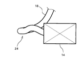
図4は、本発明の他の1つの実施形態で、給気配管18に設けられる水溜まりトラップ24を示す。図2及び図3に示す実施形態では、水溜まりトラップ24は、鉛直方向に給気配管18を湾曲させることで設けられるが、本実施形態では、鉛直方向だけでなく、水平方向にも給気配管18を湾曲させることで、水溜まりトラップ24が設けられる。例えば、図4では、給気配管18を水平方向に約180度湾曲させることで、水溜まりトラップ24が設けられる。
FIG. 4 shows a
以上、カソード側給気配管18を例とし、図2から図4を参照して説明した実施形態の水溜まりトラップ24は、アノード側給気配管16、カソード側給気配管18、及びカソード側排気配管20の、少なくとも1つに設けられる。アノード側又はカソード側のいずれか一方の給気系にのみ加湿器を備える燃料電池システムにおいても、加湿器と燃料電池とを接続する配管に、本実施形態の水溜まりトラップを設けることができる。
As described above, the cathode
なお、以上、図2から図4を参照して説明した実施形態では、加湿器と燃料電池とを接続する配管が、その加湿器側の端部から燃料電池側の端部に向かって上り勾配になるように配置される。しかし、他の1つの実施形態では、加湿器と燃料電池とを接続する配管に勾配をつけずに、配管の加湿器側の端部と燃料電池側の端部とが同程度の高さになるように配管を配置しても良い。 In the embodiment described above with reference to FIGS. 2 to 4, the pipe connecting the humidifier and the fuel cell is inclined upward from the end on the humidifier side toward the end on the fuel cell side. It is arranged to become. However, in another embodiment, the end on the humidifier side and the end on the fuel cell side of the pipe are of the same height without providing a gradient in the pipe connecting the humidifier and the fuel cell. You may arrange | position piping so that it may become.
また、図2から図4を参照して説明した実施形態の水溜まりトラップは、加湿器14の排気配管22に設けることもできる。加湿器14を車両の床下に設置する場合のように、車両部品中で加湿器14が最下方に設置されると、排気配管22の一端と接続される、加湿器の排気口が、排気配管22の、加湿器側と反対側の端部に設けられる、車両外部への排気口に対して下方になる。このとき、加湿器14の排気配管22で生じる結露水は、車両外部に排出されずに、加湿器14に流入してしまう。加湿器14の排気配管22に、水溜まりトラップを設けると、加湿器14に結露水が溜まることを抑制でき、結露水の凍結により生じる問題を回避できる。
Further, the water trap according to the embodiment described with reference to FIGS. 2 to 4 can be provided in the
10 燃料電池、12 アノード側加湿器、14 カソード側加湿器、16 アノード側給気配管、18 カソード側給気配管、20 カソード側排気配管、22 加湿器排気配管、24 水溜まりトラップ。
DESCRIPTION OF
Claims (5)
前記車両のエンジンルーム内に設置される燃料電池と、
前記燃料電池への供給気体を加湿する加湿器であって前記車両の床下に設置される加湿器と、
前記燃料電池と前記加湿器とを接続し、前記供給気体の通路となる給気配管と、
を備え、
前記給気配管には、水を溜める水溜まりトラップが設けられており、
前記水溜まりトラップは、前記給気配管において、前後の部分に対して鉛直下方に湾曲された部分を有し、さらに水平方向においても湾曲されて設けられることを特徴とする車両。 A vehicle,
A fuel cell installed in the engine room of the vehicle;
A humidifier that humidifies a gas supplied to the fuel cell and is installed under the floor of the vehicle;
An air supply pipe connecting the fuel cell and the humidifier and serving as a passage for the supply gas;
With
The air supply pipe is provided with a puddle trap for storing water ,
The vehicle according to claim 1, wherein the water trap has a portion bent vertically downward with respect to the front and rear portions of the air supply pipe, and is further curved in the horizontal direction .
前記給気配管の前記燃料電池側の端部は、前記給気配管の前記加湿器側の端部に対して上方に配置されることを特徴とする車両。 The vehicle according to claim 1,
The end of the air supply pipe on the fuel cell side is disposed above the end of the air supply pipe on the humidifier side.
前記燃料電池と前記加湿器とを接続し、前記燃料電池からの排出気体を前記加湿器に送る第1の排気配管と、
前記加湿器から排出される気体を前記車両の外部へ導く第2の排気配管と、
をさらに備え、
前記加湿器は、前記燃料電池からの前記排出気体中の水分を前記燃料電池への前記供給気体の加湿に利用し、
前記第1の排気配管及び前記第2の排気配管の少なくとも一方には、水を溜める水溜まりトラップが設けられることを特徴とする車両。 In the vehicle according to claim 1 or 2,
A first exhaust pipe connecting the fuel cell and the humidifier, and sending exhaust gas from the fuel cell to the humidifier;
A second exhaust pipe for guiding the gas discharged from the humidifier to the outside of the vehicle;
Further comprising
The humidifier uses moisture in the exhaust gas from the fuel cell to humidify the supply gas to the fuel cell,
At least one of the first exhaust pipe and the second exhaust pipe is provided with a water trap for storing water.
前記第1の排気配管の前記燃料電池側の端部は、前記第1の排気配管の前記加湿器側の端部に対して上方に配置されることを特徴とする車両。 The vehicle according to claim 3, wherein
An end of the first exhaust pipe on the fuel cell side is disposed above an end of the first exhaust pipe on the humidifier side.
前記水溜まりトラップは、配管において前記鉛直下方に湾曲された部分に溜まる水の最高水面と、配管における当該湾曲された部分の内壁の上部と、の間に間隙ができるように設けられることを特徴とする車両。 In the vehicle according to any one of claims 1 to 4 ,
The water trap is provided such that a gap is formed between the highest water surface of water accumulated in the vertically curved portion of the pipe and the upper portion of the inner wall of the curved portion of the pipe. Vehicle.
Priority Applications (6)
| Application Number | Priority Date | Filing Date | Title |
|---|---|---|---|
| JP2006145502A JP5157086B2 (en) | 2006-05-25 | 2006-05-25 | Vehicle equipped with a fuel cell |
| PCT/JP2007/059995 WO2007138855A1 (en) | 2006-05-25 | 2007-05-09 | Fuel cell system |
| CN2007800192739A CN101454935B (en) | 2006-05-25 | 2007-05-09 | Vehicle |
| US12/297,823 US9214685B2 (en) | 2006-05-25 | 2007-05-09 | Fuel cell system |
| KR1020087028681A KR101052845B1 (en) | 2006-05-25 | 2007-05-09 | Fuel cell system |
| DE112007001094.0T DE112007001094B4 (en) | 2006-05-25 | 2007-05-09 | Vehicle equipped with a fuel cell system |
Applications Claiming Priority (1)
| Application Number | Priority Date | Filing Date | Title |
|---|---|---|---|
| JP2006145502A JP5157086B2 (en) | 2006-05-25 | 2006-05-25 | Vehicle equipped with a fuel cell |
Publications (3)
| Publication Number | Publication Date |
|---|---|
| JP2007317493A JP2007317493A (en) | 2007-12-06 |
| JP2007317493A5 JP2007317493A5 (en) | 2009-06-18 |
| JP5157086B2 true JP5157086B2 (en) | 2013-03-06 |
Family
ID=38778375
Family Applications (1)
| Application Number | Title | Priority Date | Filing Date |
|---|---|---|---|
| JP2006145502A Active JP5157086B2 (en) | 2006-05-25 | 2006-05-25 | Vehicle equipped with a fuel cell |
Country Status (6)
| Country | Link |
|---|---|
| US (1) | US9214685B2 (en) |
| JP (1) | JP5157086B2 (en) |
| KR (1) | KR101052845B1 (en) |
| CN (1) | CN101454935B (en) |
| DE (1) | DE112007001094B4 (en) |
| WO (1) | WO2007138855A1 (en) |
Families Citing this family (5)
| Publication number | Priority date | Publication date | Assignee | Title |
|---|---|---|---|---|
| JP5287864B2 (en) * | 2009-04-28 | 2013-09-11 | トヨタ自動車株式会社 | Fuel cell system |
| WO2011048690A1 (en) | 2009-10-23 | 2011-04-28 | トヨタ自動車株式会社 | Fuel cell system |
| EP2648242B1 (en) * | 2010-11-30 | 2020-06-03 | Panasonic Intellectual Property Management Co., Ltd. | Battery pack |
| JP5900045B2 (en) * | 2012-03-12 | 2016-04-06 | アイシン精機株式会社 | Oxidant gas supply pipe member and fuel cell system including the same |
| WO2018221569A1 (en) * | 2017-05-31 | 2018-12-06 | 京セラ株式会社 | Fuel cell apparatus |
Family Cites Families (22)
| Publication number | Priority date | Publication date | Assignee | Title |
|---|---|---|---|---|
| JP2842517B2 (en) * | 1994-12-27 | 1999-01-06 | 三菱電機株式会社 | Fuel cell power generation equipment |
| JPH08195215A (en) * | 1995-01-13 | 1996-07-30 | Toyota Motor Corp | Fuel cell system |
| JP2001102073A (en) * | 1999-09-30 | 2001-04-13 | Daihatsu Motor Co Ltd | Fuel cell system |
| JP3832249B2 (en) | 2001-01-29 | 2006-10-11 | 日産自動車株式会社 | Fuel cell device |
| JP2002313378A (en) * | 2001-04-11 | 2002-10-25 | Asahi Kasei Corp | Fuel cell and water vapor permeation film to be favorably used in it |
| JP2002373697A (en) * | 2001-06-15 | 2002-12-26 | Toyota Motor Corp | On-vehicle fuel cell system |
| EP1398263A1 (en) * | 2002-09-16 | 2004-03-17 | Asia Pacific Fuel Cell Technologies, Ltd. | Electric scooter with fuel cell engine assembly |
| JP3807674B2 (en) * | 2002-10-01 | 2006-08-09 | 本田技研工業株式会社 | Exhaust fuel diluter |
| JP3909761B2 (en) | 2002-11-14 | 2007-04-25 | 本田技研工業株式会社 | Humidifier unit with mounting structure |
| JP2004185844A (en) | 2002-11-29 | 2004-07-02 | Suzuki Motor Corp | Fuel cell system |
| CA2518103A1 (en) * | 2003-03-03 | 2004-09-16 | Ballard Power Systems Inc. | Ambient pressure fuel cell system employing partial air humidification |
| JP2005071730A (en) | 2003-08-22 | 2005-03-17 | Honda Motor Co Ltd | Air humidification device for fuel cell |
| DE10340685A1 (en) | 2003-09-04 | 2005-06-16 | Daimlerchrysler Ag | Motor vehicle body and method for producing an integral carrier |
| US20050074640A1 (en) * | 2003-10-01 | 2005-04-07 | Matsushita Electric Industrial Co., Ltd. | Fuel cell system and operation method thereof |
| JP2005129494A (en) * | 2003-10-01 | 2005-05-19 | Matsushita Electric Ind Co Ltd | Fuel cell system and its operating method |
| JP2005149839A (en) * | 2003-11-13 | 2005-06-09 | Nissan Motor Co Ltd | Fuel cell unit |
| JP4539110B2 (en) * | 2004-02-20 | 2010-09-08 | 日産自動車株式会社 | In-vehicle structure of fuel cell system |
| JP4604514B2 (en) | 2004-03-03 | 2011-01-05 | パナソニック株式会社 | Household fuel cell cogeneration system |
| JP2006049224A (en) * | 2004-08-06 | 2006-02-16 | Ebara Ballard Corp | Fuel cell unit |
| JP4940567B2 (en) | 2005-03-31 | 2012-05-30 | パナソニック株式会社 | Polymer electrolyte fuel cell system |
| JP5022592B2 (en) | 2005-11-15 | 2012-09-12 | 株式会社東芝 | Gas-liquid separator and fuel cell power generation system equipped with gas-liquid separator |
| JP2007188641A (en) * | 2006-01-11 | 2007-07-26 | Hitachi Ltd | Fuel cell system |
-
2006
- 2006-05-25 JP JP2006145502A patent/JP5157086B2/en active Active
-
2007
- 2007-05-09 US US12/297,823 patent/US9214685B2/en active Active
- 2007-05-09 DE DE112007001094.0T patent/DE112007001094B4/en active Active
- 2007-05-09 WO PCT/JP2007/059995 patent/WO2007138855A1/en active Search and Examination
- 2007-05-09 CN CN2007800192739A patent/CN101454935B/en active Active
- 2007-05-09 KR KR1020087028681A patent/KR101052845B1/en active IP Right Grant
Also Published As
| Publication number | Publication date |
|---|---|
| KR20090005213A (en) | 2009-01-12 |
| US20090068539A1 (en) | 2009-03-12 |
| DE112007001094B4 (en) | 2017-12-28 |
| WO2007138855A1 (en) | 2007-12-06 |
| JP2007317493A (en) | 2007-12-06 |
| US9214685B2 (en) | 2015-12-15 |
| KR101052845B1 (en) | 2011-07-29 |
| DE112007001094T5 (en) | 2009-03-05 |
| CN101454935B (en) | 2012-02-01 |
| CN101454935A (en) | 2009-06-10 |
Similar Documents
| Publication | Publication Date | Title |
|---|---|---|
| US9564647B2 (en) | Fuel cell system | |
| JP4386099B2 (en) | Humidifier and fuel cell system | |
| JP5157086B2 (en) | Vehicle equipped with a fuel cell | |
| JP2006147484A (en) | Humidifier | |
| JP2006120503A (en) | Vapor-liquid separator for on-vehicle fuel cell | |
| JP2012099394A (en) | Fuel cell system | |
| JP5287864B2 (en) | Fuel cell system | |
| JP2006032134A (en) | Water storage equipment for storing water in fuel cell system and fuel cell system | |
| JP4969864B2 (en) | Fuel cell | |
| JP4594802B2 (en) | Gas sensor | |
| JP2010272337A (en) | Gas/liquid separator for fuel cell | |
| KR100916393B1 (en) | Water trap for fuel cell vehicle | |
| JP4649285B2 (en) | Gas sensor | |
| JP4630133B2 (en) | Gas sensor | |
| EP1761965A2 (en) | Fuel cell system with designed water reservoir and vehicle transporting the same | |
| JP2014191866A (en) | Fuel cell humidifier and fuel cell system | |
| JP4695441B2 (en) | Gas sensor | |
| JP5430318B2 (en) | Fuel cell stack | |
| JP2008171705A (en) | Fuel cell system | |
| JP2005156001A (en) | Hollow yarn membrane humidifier | |
| JP5450312B2 (en) | Fuel cell stack | |
| JP2010272280A (en) | Pressure detecting device | |
| JP2008226529A (en) | Fuel cell system and humidifier | |
| US20090317690A1 (en) | Apparatus for humidifying a gas flow | |
| JP2022074776A (en) | Fuel battery system |
Legal Events
| Date | Code | Title | Description |
|---|---|---|---|
| A521 | Request for written amendment filed |
Free format text: JAPANESE INTERMEDIATE CODE: A523 Effective date: 20090428 |
|
| A621 | Written request for application examination |
Free format text: JAPANESE INTERMEDIATE CODE: A621 Effective date: 20090428 |
|
| A131 | Notification of reasons for refusal |
Free format text: JAPANESE INTERMEDIATE CODE: A131 Effective date: 20120403 |
|
| A521 | Request for written amendment filed |
Free format text: JAPANESE INTERMEDIATE CODE: A523 Effective date: 20120529 |
|
| TRDD | Decision of grant or rejection written | ||
| A01 | Written decision to grant a patent or to grant a registration (utility model) |
Free format text: JAPANESE INTERMEDIATE CODE: A01 Effective date: 20121113 |
|
| A61 | First payment of annual fees (during grant procedure) |
Free format text: JAPANESE INTERMEDIATE CODE: A61 Effective date: 20121126 |
|
| R151 | Written notification of patent or utility model registration |
Ref document number: 5157086 Country of ref document: JP Free format text: JAPANESE INTERMEDIATE CODE: R151 |
|
| FPAY | Renewal fee payment (event date is renewal date of database) |
Free format text: PAYMENT UNTIL: 20151221 Year of fee payment: 3 |