JP5155031B2 - Method for sensing the distance from an air gauge and nozzle to an object - Google Patents
Method for sensing the distance from an air gauge and nozzle to an object Download PDFInfo
- Publication number
- JP5155031B2 JP5155031B2 JP2008161133A JP2008161133A JP5155031B2 JP 5155031 B2 JP5155031 B2 JP 5155031B2 JP 2008161133 A JP2008161133 A JP 2008161133A JP 2008161133 A JP2008161133 A JP 2008161133A JP 5155031 B2 JP5155031 B2 JP 5155031B2
- Authority
- JP
- Japan
- Prior art keywords
- nozzle
- gas
- flow
- output
- noise
- Prior art date
- Legal status (The legal status is an assumption and is not a legal conclusion. Google has not performed a legal analysis and makes no representation as to the accuracy of the status listed.)
- Expired - Fee Related
Links
- 238000000034 method Methods 0.000 title claims description 13
- 238000005259 measurement Methods 0.000 claims description 54
- 230000007704 transition Effects 0.000 claims description 38
- 239000006096 absorbing agent Substances 0.000 claims description 10
- 230000035939 shock Effects 0.000 claims description 10
- 230000002238 attenuated effect Effects 0.000 abstract description 6
- 235000012431 wafers Nutrition 0.000 description 9
- 230000008859 change Effects 0.000 description 8
- 230000000694 effects Effects 0.000 description 7
- 230000035945 sensitivity Effects 0.000 description 7
- 239000000463 material Substances 0.000 description 6
- 239000004065 semiconductor Substances 0.000 description 6
- 238000010586 diagram Methods 0.000 description 5
- XUIMIQQOPSSXEZ-UHFFFAOYSA-N Silicon Chemical compound [Si] XUIMIQQOPSSXEZ-UHFFFAOYSA-N 0.000 description 4
- 230000000875 corresponding effect Effects 0.000 description 4
- 238000001459 lithography Methods 0.000 description 4
- 230000010349 pulsation Effects 0.000 description 4
- 229910052710 silicon Inorganic materials 0.000 description 4
- 239000010703 silicon Substances 0.000 description 4
- 239000000758 substrate Substances 0.000 description 4
- 230000003746 surface roughness Effects 0.000 description 4
- 238000012937 correction Methods 0.000 description 3
- 230000006872 improvement Effects 0.000 description 3
- 238000004519 manufacturing process Methods 0.000 description 3
- 229910052751 metal Inorganic materials 0.000 description 3
- 239000002184 metal Substances 0.000 description 3
- 230000003287 optical effect Effects 0.000 description 3
- 238000011144 upstream manufacturing Methods 0.000 description 3
- XEEYBQQBJWHFJM-UHFFFAOYSA-N Iron Chemical compound [Fe] XEEYBQQBJWHFJM-UHFFFAOYSA-N 0.000 description 2
- PXHVJJICTQNCMI-UHFFFAOYSA-N Nickel Chemical compound [Ni] PXHVJJICTQNCMI-UHFFFAOYSA-N 0.000 description 2
- 230000005534 acoustic noise Effects 0.000 description 2
- 230000008901 benefit Effects 0.000 description 2
- 238000009826 distribution Methods 0.000 description 2
- 238000003754 machining Methods 0.000 description 2
- 230000000704 physical effect Effects 0.000 description 2
- 230000009467 reduction Effects 0.000 description 2
- 238000007788 roughening Methods 0.000 description 2
- 239000000523 sample Substances 0.000 description 2
- 239000004576 sand Substances 0.000 description 2
- JBRZTFJDHDCESZ-UHFFFAOYSA-N AsGa Chemical compound [As]#[Ga] JBRZTFJDHDCESZ-UHFFFAOYSA-N 0.000 description 1
- GPXJNWSHGFTCBW-UHFFFAOYSA-N Indium phosphide Chemical compound [In]#P GPXJNWSHGFTCBW-UHFFFAOYSA-N 0.000 description 1
- 229910001374 Invar Inorganic materials 0.000 description 1
- 238000009530 blood pressure measurement Methods 0.000 description 1
- 239000011248 coating agent Substances 0.000 description 1
- 238000000576 coating method Methods 0.000 description 1
- 239000002131 composite material Substances 0.000 description 1
- 239000000356 contaminant Substances 0.000 description 1
- 230000002596 correlated effect Effects 0.000 description 1
- 230000007423 decrease Effects 0.000 description 1
- 230000003247 decreasing effect Effects 0.000 description 1
- 230000008021 deposition Effects 0.000 description 1
- 238000009795 derivation Methods 0.000 description 1
- 238000005516 engineering process Methods 0.000 description 1
- 239000003822 epoxy resin Substances 0.000 description 1
- 238000005530 etching Methods 0.000 description 1
- 238000002474 experimental method Methods 0.000 description 1
- 238000010285 flame spraying Methods 0.000 description 1
- 239000012530 fluid Substances 0.000 description 1
- 239000011521 glass Substances 0.000 description 1
- 229910052742 iron Inorganic materials 0.000 description 1
- 230000001788 irregular Effects 0.000 description 1
- 238000012986 modification Methods 0.000 description 1
- 230000004048 modification Effects 0.000 description 1
- 229910052759 nickel Inorganic materials 0.000 description 1
- 229920000647 polyepoxide Polymers 0.000 description 1
- 230000003584 silencer Effects 0.000 description 1
- 230000001743 silencing effect Effects 0.000 description 1
- 230000001960 triggered effect Effects 0.000 description 1
- 230000000007 visual effect Effects 0.000 description 1
Images


Classifications
-
- G—PHYSICS
- G01—MEASURING; TESTING
- G01B—MEASURING LENGTH, THICKNESS OR SIMILAR LINEAR DIMENSIONS; MEASURING ANGLES; MEASURING AREAS; MEASURING IRREGULARITIES OF SURFACES OR CONTOURS
- G01B13/00—Measuring arrangements characterised by the use of fluids
- G01B13/12—Measuring arrangements characterised by the use of fluids for measuring distance or clearance between spaced objects or spaced apertures
-
- D—TEXTILES; PAPER
- D06—TREATMENT OF TEXTILES OR THE LIKE; LAUNDERING; FLEXIBLE MATERIALS NOT OTHERWISE PROVIDED FOR
- D06C—FINISHING, DRESSING, TENTERING OR STRETCHING TEXTILE FABRICS
- D06C13/00—Shearing, clipping or cropping surfaces of textile fabrics; Pile cutting; Trimming seamed edges
-
- G—PHYSICS
- G01—MEASURING; TESTING
- G01B—MEASURING LENGTH, THICKNESS OR SIMILAR LINEAR DIMENSIONS; MEASURING ANGLES; MEASURING AREAS; MEASURING IRREGULARITIES OF SURFACES OR CONTOURS
- G01B13/00—Measuring arrangements characterised by the use of fluids
- G01B13/02—Measuring arrangements characterised by the use of fluids for measuring length, width or thickness
Abstract
Description
[0001] 本発明は、非常に小さい距離を検出する装置及び方法に、特に近接覚に関する。 [0001] The present invention relates to an apparatus and method for detecting a very small distance, and in particular to proximity.
[0002] 自動化した多くの製造プロセスは、製造ツールと加工中の製品又は材料の表面との間の距離を感知する必要がある。半導体リソグラフィなどの幾つかの状況では、この距離を、数ナノメートルに近づく正確度で測定しなければならない。 [0002] Many automated manufacturing processes require sensing the distance between the manufacturing tool and the surface of the product or material being processed. In some situations, such as semiconductor lithography, this distance must be measured with an accuracy approaching a few nanometers.
[0003] このような正確度の近接覚センサの生成に伴う難問は、特にリソグラフィシステムの状況で重大である。この状況では、非侵入的であり、非常に小さい距離を精密に検出する能力を有すること以外に、近接覚センサは、汚染物質を導入したり、微小な温度変化を引き起こしたり、通常は半導体ウェーハである加工表面に接触したりすることができない。このような状況が発生すると、半導体の品質を大幅に低下させるか、損なってしまうことがある。 [0003] The challenges associated with generating such accurate proximity sensors are particularly serious in the context of lithography systems. In this situation, in addition to being non-intrusive and having the ability to accurately detect very small distances, proximity sensors introduce contaminants, cause minute temperature changes, usually semiconductor wafers Or cannot touch the processed surface. When such a situation occurs, the quality of the semiconductor may be significantly reduced or lost.
[0004] 非常に小さい距離を測定するために、様々なタイプの近接覚センサが入手可能である。近接覚センサの例は、キャパシタンス及び光学ゲージを含む。これらの近接覚センサは、リソグラフィシステムで使用する場合に深刻な欠点を有する。というのは、ウェーハに付着する材料の物理的特性が、これらのデバイスの精度に影響するからである。例えば、キャパシタンスゲージは、電荷の濃度に依存し、1タイプの材料(例えば金属)が集中している位置では、偽の近接値を生じることがある。新種のウェーハが、ガリウム砒素(GaAs)及びリン化インジウム(InP)などの非導電性及び/又は感光性材料で作成されるか、その付着物を含む場合は、別のクラスの問題が発生する。これらの場合、キャパシタンス及び光学ゲージが、偽の結果を提供することがある。 [0004] Various types of proximity sensors are available for measuring very small distances. Examples of proximity sensors include capacitance and optical gauges. These proximity sensors have serious drawbacks when used in lithography systems. This is because the physical properties of the material attached to the wafer affect the accuracy of these devices. For example, a capacitance gauge depends on the concentration of charge and may produce false proximity values at locations where one type of material (eg, metal) is concentrated. Another class of problems arise when new types of wafers are made of or contain deposits of non-conductive and / or photosensitive materials such as gallium arsenide (GaAs) and indium phosphide (InP). . In these cases, the capacitance and optical gauge may provide false results.
[0005] エアゲージセンサは通常、脱水して濾過した空気流を表面(例えばシリコンウェーハ)上に放出し、次にその背圧を測定し、測定ノズルとその表面との間の距離を割り出す。より感度が高いエアゲージセンサは、基準表面及び測定表面上に空気流を放出する基準及び測定ノズルの両方を使用して、表面距離を割り出す。エアゲージセンサは、電荷の濃度にも、ウェーハ表面の電気、光学及び他の物理的特性にも脆弱でない。しかし、現在の半導体製造技術では、近接性をナノメートルのオーダの高精度で測定する必要がある。残念ながら初期のエアゲージセンサは、今日のリソグラフィの精度要件を満たさないものが多い。ナノメートルの再現性及び位置合わせ正確度に関する今日の要件は、全体的に産業界で現在獲得可能な要件よりもさらに厳格である。また、以前のデバイスは、特定の温度範囲全体での寸法安定性に対する今日の要求を満たしていない。 [0005] An air gauge sensor typically discharges a dehydrated and filtered air stream onto a surface (eg, a silicon wafer) and then measures its back pressure to determine the distance between the measurement nozzle and the surface. More sensitive air gauge sensors use both a reference and measurement nozzle that emits an air flow over the reference and measurement surfaces to determine the surface distance. Air gauge sensors are not vulnerable to charge concentrations or to electrical, optical and other physical properties of the wafer surface. However, with current semiconductor manufacturing technology, it is necessary to measure proximity with high accuracy on the order of nanometers. Unfortunately, many early air gauge sensors do not meet the accuracy requirements of today's lithography. Today's requirements for nanometer reproducibility and alignment accuracy are generally more stringent than those currently available in industry. Also, previous devices do not meet today's requirements for dimensional stability over a specific temperature range.
[0006] 必要とされているのは、寸法安定性も呈するガスゲージ近接覚センサによって、精確なナノメートル規模の測定を提供するシステム及び方法である。 [0006] What is needed is a system and method that provides accurate nanometer scale measurements with a gas gauge proximity sensor that also exhibits dimensional stability.
[0007] 従来のエアゲージは、層流相による流量で作動する。本発明の実施形態によるガスゲージは、層流と乱流の間の遷移領域における流れに相当する流量で作動する。遷移領域は、約2100と5100の間のレイノルズ数を有する流れを含む。 [0007] A conventional air gauge operates at a flow rate due to a laminar phase. Gas gauges according to embodiments of the present invention operate at a flow rate that corresponds to the flow in the transition region between laminar and turbulent flow. The transition region includes a flow having a Reynolds number between about 2100 and 5100.
[0008] 従来の相では、ノズル面の表面における圧力低下は、その表面の摩擦係数がレイノルズ数の増加とともに増加するにつれて増大する。表面摩擦係数値は2つの表面、つまりノズル面及び測定表面に基づく。シリコンウェーハの測定表面とは干渉できないが、ノズル面の表面を粗くして、ノズル表面の摩擦係数を効果的に増加させることができる。表面は、例えばノズル面を様々な「砂粗さ」までショットブラストする、ノズル面に粗い酸化被膜を火炎溶射する、ノズル面に円形の同心円リングを機械加工するか、それを突出させる、多数の小さい半球形窪みを、その配置構成を互い違いにしながら、ノズル面に又はノズル面から機械加工する、及び/又は数十の互い違いのピンをノズル面に導入することによって粗くすることができるが、それに制限されない。ノズル面の表面積及びその粗さは、エアゲージの圧力低下を遷移流相にて扱う際に重要である。 [0008] In the conventional phase, the pressure drop at the surface of the nozzle surface increases as the coefficient of friction of the surface increases with increasing Reynolds number. The surface friction coefficient value is based on two surfaces: the nozzle surface and the measurement surface. Although it cannot interfere with the measurement surface of the silicon wafer, the surface of the nozzle surface can be roughened to effectively increase the friction coefficient of the nozzle surface. The surface can be shot blasted to various "sand roughness", for example, flame spraying a rough oxide coating on the nozzle surface, machining a circular concentric ring on the nozzle surface, or protruding it. Small hemispherical depressions can be roughened by machining into and out of the nozzle face and / or introducing dozens of staggered pins into the nozzle face while staggering its arrangement. Not limited. The surface area of the nozzle surface and its roughness are important when handling the pressure drop of the air gauge in the transition flow phase.
[0009] 流量増加によって発生するノイズは、1つ又は複数のヘルムホルツ減衰器を使用することによって減衰することができる。 [0009] Noise generated by increased flow can be attenuated by using one or more Helmholtz attenuators.
[0010] 本発明のさらなる実施形態、特徴及び利点、さらに本発明に関するこれらの様々な実施形態の構造及び動作について、添付図面を参照しながら、以下で詳細に説明する。 [0010] Further embodiments, features and advantages of the present invention, as well as the structure and operation of these various embodiments related to the present invention, are described in detail below with reference to the accompanying drawings.
[0011] 本発明を添付図面に関して説明する。図面では、同様の参照番号は同一の、又は機能的に同様の要素を示す。 [0011] The present invention will be described with reference to the accompanying drawings. In the drawings, like reference numbers indicate identical or functionally similar elements.
[0022] 本明細書では、本発明を特定の用途の例示的実施形態について説明するが、本発明がそれに制限されないことを理解されたい。本明細書で提供される教示に接した当業者には、本発明が非常に有用な範囲及び追加の分野内で、追加の変形、用途及び実施形態が認識される。 [0022] While the invention is described herein with reference to illustrative embodiments for particular applications, it should be understood that the invention is not limited thereto. Those skilled in the art who have access to the teachings provided herein will recognize additional variations, applications, and embodiments within the scope and additional scope of the present invention.
[0023] 図1は、ガスゲージ近接覚センサ100の線図を提供する。ガスゲージ近接覚センサ100は、本発明の1つ又は複数の実施形態を通して改善できる1タイプの近接覚センサであり、本発明の範囲を制限するものではない。ガスゲージ近接覚センサ100はガス圧力調整器105、質量流量制御装置106、中心流路112、測定流路116、基準流路118、緩衝器120、緩衝器122、測定プローブ128、基準プローブ130、ブリッジ流路136及び質量流量センサ138を含む。ガス供給部102が、ガスを所望の圧力でガスゲージ近接覚センサ100内に噴射する。
FIG. 1 provides a diagram of a gas
[0024] 中心流路112は、ガス供給部120をガス圧力調整器105及び質量流量制御装置106に接続し、次に接合部114で終了する。ガス圧力調整器105及び質量流量制御装置106は、ガスゲージ近接覚センサ100内で一定の流量を維持する。
The
[0025] ガスは、流路112に取り付けられたアキュムレータ108で、質量流量制御装置106から流路112へと強制的に入る。幾つかの状況では、質量流量制御装置106と接合部114の間に緩衝器を配置することができる。センサ100は、接合部114の分流部の各脚部に配置された2つの緩衝器120及び122を有する。緩衝器は、ガス供給部102によって導入されたガスの乱流を、したがってノイズを減少させ、抵抗要素としても作用する。他の実施形態では、オリフィスなどの他のタイプの抵抗要素を使用することができるが、オリフィスは乱流を減少させない。
The gas is forcibly entered from the
[0026] ガスは、質量流量制御装置106を出ると、中心流路112を接合部114へと移動する。中心流路112は接合部114で終了し、測定流路116と基準流路118とに分割する。質量流量制御装置106は、十分に少ない流量でガスを噴射して、システム全体に層流及び非圧縮性流体流れを提供し、これは望ましくない空気ノイズの生成を最小限に抑える。同様に、システムの幾何形状はほぼ、質量流量制御装置106によって確立された層流特性を維持するようなサイズにすることができる。
[0026] As the gas exits the
[0027] ブリッジ流路136は、測定流路116と基準流路118の間に結合される。ブリッジ流路136は、接合部124で測定流路116に接続する。ブリッジ流路136は、接合部126で基準流路118に接続する。一例では、接合部114と接合部124の間の距離と、接合部114と接合部126の間の距離とは等しく、これは流れの対称性及びガスゲージの性能に役立つ。
The
[0028] ガスゲージ近接覚センサ100内の全ての流路は、それを通ってガスが流れることができる。流路112、116、118及び136は、導管(管、パイプなど)、又はセンサ100を通るガスの流れを封じ込め、案内することができる任意の他のタイプの構造で構成することができる。流路は例えば局所的乱流又は流れの不安定性を生じることによって、空気ノイズを導入するような急な曲がり、凸凹又は不必要な障害を有さないことが望ましい。測定流路116と基準流路118の全長が等しいか、他の例では等しくなくてよい。しかし、対称性を失うと、センサ100の性能を妨げ、追加の流れ補正率を必要とすることがある。
[0028] All channels within the gas
[0029] 基準流路118は基準ノズル130内で終了する。同様に、測定流路116は測定ノズル128内で終了する。基準ノズル130は基準表面134上に配置される。測定ノズル128は測定表面132上に配置される。リソグラフィの状況では、測定表面132は、基板、半導体ウェーハ、ウェーハを支持するステージ、フラットパネルディスプレイ、ガラス基板、印刷ヘッド、マイクロ又はナノ流体装置などであることが多い。基準表面134は平坦な金属板でよいが、この例に制限されない。ガス供給部102によって噴射されたガスは、各ノズル128、130から放出され、測定表面132及び基準表面134に衝突する。上述したように、ノズルと対応する測定又は基準表面との間の距離をスタンドオフと呼ぶ。
The
[0030] 1つの実施形態では、基準ノズル130は、既知の基準スタンドオフ142がある状態で、固定された基準表面134の上方に配置される。測定ノズル128は、未知の測定スタンドオフ140がある状態で、測定表面132の上方に配置される。既知の基準スタンドオフ142は、最適なスタンドオフを表す所望の一定の値に設定される。このような構成で、測定ノズル128の上流の背圧は、未知の測定スタンドオフ140の関数であり、基準ノズル130の上流の背圧は、既知の基準スタンドオフ142の関数である。スタンドオフ140と142が等しい場合、この構成は対称であり、ブリッジは釣り合っている。その結果、ブリッジ流路136を通るガスの流れはない。他方で、測定スタンドオフ140と基準スタンドオフ142が異なる場合、その結果生じる測定流路116と基準流路118の間の圧力差は、質量流量センサ138を通るガスの流れを誘発する。
In one embodiment, the
[0031] 質量流量センサ138は、ブリッジ流路136に沿って例えば中心位置に配置される。質量流量センサ136は、測定流路116と基準流路118の間の圧力差によって誘発されたガスの流れを感知する。これらの圧力差は、測定表面132の垂直位置が変化した結果として生じる。対称のブリッジの場合、測定スタンドオフ140と基準スタンドオフ142が等しい場合、スタンドオフは、表面132、134と比較して、ノズル128、130の両方で同じである。質量流量センサ138は、測定流路と基準流路の間に圧力差がないので、質量流量を検出しない。測定スタンドオフ140と基準スタンドオフ142とに差があると、測定流路116と基準流路118との圧力に差が生じる。非対称の構成には、適切なオフセットを導入することができる。
The
[0032] 質量流量センサ138は、圧力差又は不均衡によって導入されたガス流を感知する。圧力差はガスの流れを引き起こし、その流量は、測定スタンドオフ140の一意の関数である。つまり、ガスゲージ100に入る流量が一定であるとすると、測定流路116と基準流路118のガス圧力の差は、スタンドオフ140と142の大きさの差の関数である。基準スタンドオフ142が既知のスタンドオフに設定されると、測定流路116と基準流路118のガス圧力の差は、測定スタンドオフ140(つまり測定表面132と測定ノズル128の間の未知のスタンドオフ)のサイズの関数である。
[0032] The
[0033] 質量流量センサ138は、ブリッジ流路136を通るどの方向のガス流も検出する。ブリッジの構成のせいで、流路116と118の間に圧力差が生じた場合のみ、ブリッジ流路136を通るガスの流れが生じる。圧力の不均衡が存在すると、質量流量センサ138がその結果のガス流を検出し、適切な制御機能を開始することができる。質量流量センサ138は、視覚的ディスプレイ、音響表示、コンピュータ制御のシステム又は他の信号発生手段を通して、感知した流れの表示を提供することができる。あるいは、質量流量センサの代わりに、差圧センサを使用することができる。差圧センサは、2つの流路間の圧力差を測定し、これは測定スタンドオフと基準スタンドオフ間の差の関数である。
[0034] 近接覚センサ100は、本発明の1つ又は複数の実施形態から恩恵を受けることができるノズルを有するデバイスの一例として提供されている。本発明のこれらの例示的実施形態は、近接覚センサ100のみと使用することに制限されるものではない。むしろ、本発明の例示的実施形態は、他のタイプの近接覚センサを改善するために使用することができる。
[0034]
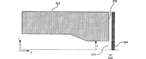
[0035] 図2は、例示的測定ノズル202のさらなる詳細を示す図である。ノズル202は、例えば図1の測定ノズル128と同様でよい。図2では、ノズル202は対象物又は測定表面204に近接している。ノズル202は、実質的に表面204と平行であるノズル面206を有する。ノズル面106は、表面204から距離208だけ離間されている。ガスは通常、オリフィス210を通ってz方向にノズルから流出し、次にノズル面206と表面204の間を半径方向外側に流れる。ノズル面206でのガスの圧力低下は、距離208の高さを表す。
FIG. 2 is a diagram illustrating further details of the
流量の性能への効果
[0036] 以上で示したように、測定ノズルと測定表面の間の距離(例えば図2のノズル面206と表面204間の距離208)は、安定した流量でガスの流れを出力し、ノズル面206のガス流れの圧力低下(背圧とも呼ばれる)を測定することによって割り出すことができる。性能を改善するために、局所圧力低下とギャップ高さとの相関を上げる。任意のガス流量及びギャップ高さについて、圧力低下を、ノズル面の摩擦係数にノズル面の半径方向長さを掛けた値に関連づけることができる。
Effect of flow rate on performance
As described above, the distance between the measurement nozzle and the measurement surface (for example, the
[0037] 以前のゲージは、「層流」領域のガス流量で作動していた。このような流量は、これらのシステムが必要とする測定レベルには十分であった。しかし、これらの層流ガスゲージは、ナノメートル範囲で距離を正確に測定するほど十分に感度が高くない。ナノメートルレベルの測定感度を有するようにゲージの性能を向上させるには、ゲージの利得を向上させねばならない。利得を向上させるには、測定表面からのノズル高さの単位変化当たりのノズル圧力低下を改善しなければならない。 [0037] Previous gauges operated at gas flow rates in the "laminar flow" region. Such a flow rate was sufficient for the measurement level required by these systems. However, these laminar gas gauges are not sensitive enough to accurately measure distances in the nanometer range. In order to improve the performance of the gauge to have nanometer level measurement sensitivity, the gain of the gauge must be improved. To increase the gain, the nozzle pressure drop per unit change in nozzle height from the measurement surface must be improved.
[0038] ノズル面での摩擦係数を増加させると、測定表面での圧力低下が増大する。しかし、この圧力低下のシナリオの物理的性質は、層流領域ではなく「遷移流」領域の局所レイノルズ数を有するノズル表面でしか作用しない。レイノルズ数(Re)は以下のように計算される。
![]()
![]()
[0039] 図3は、横軸にレイノルズ数、縦軸に摩擦係数を示す対数グラフである。図3は通常、「ムーディのプロット」と呼ばれる。ムーディのプロットに関するさらなる説明は、例えばL.F. Moodyの「Friction Factors for Pipe Flow」(ASME Trans.、66巻671〜684ページ、1944年)で見ることができ、これは参照により全体が本明細書に組み込まれる。 FIG. 3 is a logarithmic graph in which the horizontal axis represents the Reynolds number and the vertical axis represents the friction coefficient. FIG. 3 is commonly referred to as a “Moody plot”. Further explanation of Moody's plots can be found, for example, in LF Moody's “Friction Factors for Pipe Flow” (ASME Trans., 66, 671-684, 1944), which is hereby incorporated by reference in its entirety. Incorporated.
[0040] 以前のガスゲージは、約200〜300のレイノルズ数を有する流量で作動していた。図3に示すように、このような流量は層流領域内にある。層流領域は曲線302によって規定される。約2100のレイノルズ数で、ガス流量は層流領域から遷移流領域へと変化し始める。遷移流領域は曲線304によって規定される。レイノルズ数が増加するにつれ、流量は曲線306によって規定される完全な乱流へと切り替わり始まる。レイノルズ数の増加は通常、層流相内で作動している場合に回避される。というのは、ノズルの摩擦係数を低下させ、それによってゲージから入手可能な利得を減少させるからである。しかし、レイノルズ数が層流相を過ぎて遷移流相まで増加すると、レイノルズ数が増加するにつれ、摩擦係数が増加し始める。 [0040] Previous gas gauges were operated at a flow rate having a Reynolds number of about 200-300. As shown in FIG. 3, such a flow rate is in the laminar flow region. The laminar flow region is defined by curve 302. At a Reynolds number of about 2100, the gas flow rate begins to change from a laminar flow region to a transition flow region. The transition flow region is defined by curve 304. As the Reynolds number increases, the flow rate begins to switch to full turbulence defined by curve 306. An increase in Reynolds number is usually avoided when operating in a laminar phase. This is because it reduces the coefficient of friction of the nozzle, thereby reducing the gain available from the gauge. However, as the Reynolds number increases past the laminar flow phase to the transitional flow phase, the coefficient of friction begins to increase as the Reynolds number increases.
[0041] 遷移領域で作動するノズルの流れ場は、層流領域で作動している従来のノズルのそれと摩擦性能が逆であり、後者はレイノルズ数が増加するにつれて摩擦係数がゆっくり低下する。このような摩擦の低下の感度は、図3の曲線302と304の勾配の差によって測定される。摩擦流のハーゲン・ポアズイユの法則に従う曲線302は、約m1=−1.0の勾配を有し、曲線304は約m2=+1.39の勾配を有する。曲線304の勾配の記号は、摩擦反転の影響を表すが、重要なのは曲線304の方が約39%急な勾配を呈することである。層流領域から遷移流領域への変化は、速度プロフィールが変化する流路の流れを物理的に示唆する。速度プロフィールは、放物線状の速度分布から修正され、切れた双曲線の速度分布に変化する。遷移流領域内の摩擦はノズルの流れの圧力低下に影響する。というのは、曲線304の勾配が正方向に急であることによって見られるように、このゾーン内で摩擦係数が最も劇的に変化するからである。これによってレイノルズ数が増加する結果、板からノズル距離への関連する圧力低下の感度が上昇し、ギャップ高さの測定でさらなる応答性相対利得を生じる。 [0041] The flow field of a nozzle operating in the transition region is opposite in friction performance to that of a conventional nozzle operating in the laminar flow region, with the latter having a slowly decreasing coefficient of friction as the Reynolds number increases. The sensitivity of such friction reduction is measured by the difference in slope between curves 302 and 304 in FIG. Curve 302 according to Hagen-Poiseuille's law of friction flow has a slope of about m 1 = −1.0, and curve 304 has a slope of about m 2 = + 1.39. The slope symbol of curve 304 represents the effect of friction reversal, but what is important is that curve 304 exhibits a slope that is about 39% steeper. The change from the laminar flow region to the transition flow region physically suggests a flow in the channel where the velocity profile changes. The velocity profile is modified from a parabolic velocity distribution and changes to a truncated hyperbolic velocity distribution. Friction in the transition flow region affects the pressure drop in the nozzle flow. This is because the coefficient of friction changes most dramatically within this zone, as seen by the sharp slope of curve 304 in the positive direction. This increases the Reynolds number, which increases the sensitivity of the associated pressure drop from plate to nozzle distance, resulting in additional responsive relative gains in the gap height measurement.
[0042] 式1に見られるように、レイノルズ数は、使用ガスの密度、ノズル面上でのガスの半径方向速度、ノズルの複雑な特徴的直径、及び使用ガスの速度に依存する。遷移流ノズルに、層流ノズルで使用したものと同じガス(例えば空気など)を使用すると、ガスの密度及び速度を変化させることができない。レイノルズ数を増加させる方法は、ノズルを通るガスの速度を上げるか、ノズルの特徴的直径を増加させるしかない。
[0042] As seen in
[0043] ノズルの直径を増加させることは本質的に困難であるので、本発明の実施形態では、ノズルを通るガスの速度(流量とも呼ばれる)を上げることによって、レイノルズ数を増加させる。従来の層流ゲージは通常、約1000sccm(標準立方センチメートル/分)のガス体積流量を呈する。流量のみを変化させながら、レイノルズ数を、約2100のレイノルズ数を有する遷移流相まで増加させると、約6800sccmの流量になる。 [0043] Since increasing the nozzle diameter is inherently difficult, embodiments of the present invention increase the Reynolds number by increasing the velocity of the gas through the nozzle (also referred to as the flow rate). Conventional laminar flow gauges typically exhibit a gas volume flow rate of about 1000 sccm (standard cubic centimeters / minute). Increasing the Reynolds number to a transition flow phase having a Reynolds number of about 2100 while changing only the flow rate results in a flow rate of about 6800 sccm.
[0044] 図4は、様々なガス流量について、図2のノズル面206でオリフィス210から半径方向外側に延在する様々な位置におけるレイノルズ数の例示的変化を示す。横軸には、半径方向の測定位置がmm単位で図示され、縦軸には、ノズル面と測定表面との間のギャップにおけるガス流のレイノルズ数が図示されている。半径方向の位置の増加に伴うレイノルズ数の変化は、2つの事象、つまり1)局所的レイノルズ数とともに変化する局所的摩擦係数によるノズル表面でのガスの圧力低下の変化、及び2)半径方向外側への移動に伴う流れの局所的な特徴的寸法(D)の一定の変化、を示す。Dは、流れが半径方向に出るにつれ、ノズル面の局所水力直径(Dh)の変化の関数として変化し、下式のように定義される。
![]()
![]()
[0045] 曲線402は、従来の層流ノズル(例えば約1000sccmの流量)の圧力低下を示す。曲線402のレイノルズ数は約230と約625の間である。曲線404は、低い方の流量(例えば約6800sccmの流量)における遷移流ノズルの圧力低下を示す。曲線404の平均レイノルズ数は約2900である。曲線406は、高い方の流量(例えば約9000sccmの流量)における遷移流ノズルの圧力低下を示す。曲線406の平均レイノルズ数は約3900である。図示のように、ノズル面での圧力低下は、曲線306が最大である。圧力低下がより大きいので、高い方の流量で作動する遷移流ノズルの方が、低い方の流量で作動する遷移流ノズルよりも小さい圧力変化に対する感度が高く、後者はそれでも、層流ノズルよりも圧力変化に対する感度が高い。
[0045]
[0046] 図5は、ノズルの作動に従って遷移流摩擦係数相と層流摩擦係数相で入手可能な理論的利得量を示す。本明細書で使用する利得は、135ミクロンで計算したギャップ高さに対して任意の圧力低下曲線の局所的勾配を求めることによって割り出される。横軸には、ノズルギャップ高さをミクロン単位で示し、縦軸には、ノズル面での全圧力低下をkPa単位で示す。曲線502は、約1000sccmという流量で作動する層流ノズルの理論的利得を示す。曲線502の利得は約0.024kPa/ミクロンである。曲線504は、約10−6の相対粗さを有し(例えば滑らかな表面)、約4900sccmの比較的低い流量で作動する遷移流ノズルの理論的利得を示す。曲線504の利得は約0.512kPa/ミクロンである。曲線506は、約10-6の相対粗さを有し、約6800sccmという比較的高い流量で作動する遷移流ノズルの理論的利得を示す。曲線506の利得は約0.983kPa/ミクロンである。曲線508は、約0.05の相対粗さを有し、約9000sccmという比較的高い流量で作動する遷移流ノズルの理論的利得を示す。曲線508の利得は約1.759kPa/ミクロンである。
[0046] FIG. 5 shows the theoretical gains available for the transition flow coefficient coefficient phase and the laminar flow coefficient coefficient phase according to the operation of the nozzle. As used herein, the gain is determined by determining the local slope of any pressure drop curve for the gap height calculated at 135 microns. The horizontal axis shows the nozzle gap height in microns, and the vertical axis shows the total pressure drop on the nozzle surface in kPa.
[0047] 図5に示すように、層流流量(例えば曲線502)から低い遷移流流量システム(例えば曲線504)へと遷移することによって、約0.024kPa/ミクロンから約0.512kPa/ミクロンという理論的な利得の改善(約21×の利得)を達成することができる。さらに、層流流量(例えば曲線502)から高い遷移流流量(例えばそれぞれ曲線506及び曲線508)へと遷移することによって、約0.512kPa/ミクロンから約0.983kPa/ミクロン(約41×の全体的利得)、さらには約1.759kPa/ミクロンへ(約73×の全体的利得)という理論的なノズル利得の改善を達成することができる。
[0047] As shown in FIG. 5, by transitioning from a laminar flow rate (eg, curve 502) to a low transition flow rate system (eg, curve 504), from about 0.024 kPa / micron to about 0.512 kPa / micron. A theoretical gain improvement (approximately 21 × gain) can be achieved. Further, by transitioning from a laminar flow rate (eg, curve 502) to a higher transition flow rate (eg,
[0048] 図5は、絶対利得に関して利得を示しているが、常に層流であるかのように流れを理論的に処理することによって、相対利得も割り出すことができる。この相対利得を割り出すには、遷移領域が存在するという実際の物理的性質を考慮せずに、層流補正を使用して、ノズルの流量増加と、それに対応する圧力低下という孤立した事例を厳密に評価する。このような結果は、(約1000sccmと比較して)約6800sccmの流量で流し、図3の曲線302の元の層流摩擦係数を使用して、約2900のレイノルズ数に外挿することによって、厳密な相対利得を示す。これは、約0.82kPa/ミクロンという相対利得を生成する(約39×の利得)。この相対利得の結果を、図5に示す約0.983という絶対利得の結果と比較すると、図3の曲線304の遷移流相へと移動することによって、約20%のさらなる利得の増加を獲得できることが明白である。滑らかな表面の相対粗さである約10-6より大きい相対粗さを有するノズル面によってトリガした場合に、流れの中では自然にこのような流れ場の遷移に従う。 [0048] Figure 5 shows gain in terms of absolute gain, but relative gain can also be determined by theoretically treating the flow as if it were always laminar. To determine this relative gain, laminar flow correction is used to accurately isolate the isolated case of nozzle flow increase and corresponding pressure drop without considering the actual physical nature of the existence of a transition region. To evaluate. Such a result is obtained by flowing at a flow rate of about 6800 sccm (compared to about 1000 sccm) and extrapolating to a Reynolds number of about 2900 using the original laminar friction coefficient of curve 302 of FIG. Strict relative gain is shown. This produces a relative gain of about 0.82 kPa / micron (about 39 × gain). Comparing this relative gain result with the absolute gain result of about 0.983 shown in FIG. 5, gaining an additional gain of about 20% by moving to the transitional flow phase of curve 304 of FIG. Obviously we can do it. Such a flow field transition naturally follows in the flow when triggered by a nozzle face having a relative roughness greater than about 10 −6, which is the relative roughness of the smooth surface.
[0049] 絶対利得に関して、流れを約7倍(100sccmから6800sccmへと)増加させると、約5000のレイノルズ数値まで、約41倍以上のノズル利得の大きい改善がある。流量が増加すると、遷移領域で作動することができ、ノズルの圧力低下が約5kPaから約225kPa以上へと増加する。圧力低下が増加するだけでなく、このような損は計器の高い感度の必要性も低下させる。というのは、利得が増加すると、その結果のギャップ高さを測定するために使用する圧力変換器の感度を低下させることができるからである。 [0049] With respect to absolute gain, increasing the flow by about 7 times (from 100 seem to 6800 seem) gives a significant improvement in nozzle gain of about 41 times or more, to a Reynolds number of about 5000. As the flow rate increases, it can operate in the transition region and the nozzle pressure drop increases from about 5 kPa to about 225 kPa and above. Not only does the pressure drop increase, but such losses also reduce the need for high instrument sensitivity. This is because increasing the gain can reduce the sensitivity of the pressure transducer used to measure the resulting gap height.
ノズル面の粗さ
[0050] 以前のガスゲージは、約200〜300のレイノルズ数を有する層流流量で作動していた。このようなレイノルズ数及び約2100のレイノルズ数までは、ノズル面の表面相対粗さ(RR)は事実上、圧力低下に影響を及ぼさない。層来粗さとは、式2に示すように、ノズル幾何形状の水力直径とギャップ高さとの組合せに対する再現可能な表面凹凸の比率として定義される。しかし、遷移流相のレイノルズ数(2100<Re<5100)では、ゲージの利得と相関するノズルの摩擦係数が、ノズル面の表面粗さに応じて変化し得る。図3の曲線308に示すように、ノズル面の粗さの増加は、達成可能な最大摩擦係数を約0.1の値まで増加させるのに役立つ。遷移流領域では、達成可能な摩擦係数が、上をガスが流れるノズル面の粗さに依存することが実験で示されている。滑らかなノズル面の場合は、約3000のレイノルズ数で約0.045の最大摩擦係数が達成可能である。非常に粗い表面(RR>0.05)を有するノズルでは、約4200から約5100のレイノルズ数で約0.08から約0.01の最大摩擦係数(fTRANSITIONAL)が達成可能である。その結果、ノズル面の表面((L/D)BAR)上の任意のギャップ高さ(H)での圧力低下(ΔP)も、以下のようにレイノルズ数の増加に比例して増加する。
![]()
[0050] Previous gas gauges were operated at laminar flow rates having a Reynolds number of about 200-300. Up to such a Reynolds number and a Reynolds number of about 2100, the surface relative roughness (RR) of the nozzle face has virtually no effect on the pressure drop. Layered roughness is defined as the ratio of reproducible surface irregularities to the combination of nozzle geometry hydraulic diameter and gap height, as shown in Equation 2. However, at the Reynolds number of the transition flow phase (2100 <Re <5100), the coefficient of friction of the nozzle that correlates with the gain of the gauge can vary depending on the surface roughness of the nozzle surface. As shown by curve 308 in FIG. 3, increasing the roughness of the nozzle surface helps increase the maximum achievable coefficient of friction to a value of about 0.1. Experiments have shown that in the transition flow region, the achievable coefficient of friction depends on the roughness of the nozzle surface over which the gas flows. For a smooth nozzle surface, a maximum coefficient of friction of about 0.045 can be achieved with a Reynolds number of about 3000. For nozzles with very rough surfaces (RR> 0.05), a maximum coefficient of friction (f TRANSITIONAL ) of about 0.08 to about 0.01 can be achieved with a Reynolds number of about 4200 to about 5100. As a result, the pressure drop (ΔP) at an arbitrary gap height (H) on the surface ((L / D) BAR ) of the nozzle surface also increases in proportion to the increase in Reynolds number as follows.
![]()
[0051] 図5は、上述したように遷移流相で得られるノズルの理論的利得を示す。曲線506は、比較的高い流量における遷移流ノズルの利得を示し、利得は比較的滑らかな表面を有するノズルに基づく。曲線508は、ノズルが比較的高い流量で作動した場合に、粗くした表面を有する遷移流ノズルの理論的利得を示す。
[0051] FIG. 5 shows the theoretical gain of the nozzle obtained in the transitional flow phase as described above.
[0052] これで、従来の層流ノズルと比較すると、ノズル面の表面を粗くし、遷移流領域でゲージを作動させることによって、ガスゲージの性能を向上させることができる。 [0052] As compared with the conventional laminar flow nozzle, the performance of the gas gauge can be improved by roughening the surface of the nozzle surface and operating the gauge in the transition flow region.
[0053] ノズル面は、これに特定の表面凹凸を加えることによって粗くすることができる。ナノメートル範囲で高さを測定するには、表面の凹凸は例えばナノ又はマイクロ規模の凹凸でよい。ノズル表面を粗くするには様々な方法がある。 [0053] The nozzle surface can be roughened by adding specific surface irregularities thereto. In order to measure the height in the nanometer range, the surface irregularities may be, for example, nano- or micro-scale irregularities. There are various methods for roughening the nozzle surface.
[0054] 1つの例では、ノズル面を、図3などの流れ抵抗に関するムーディのプロットによって規定されたレベルと同等の様々な「砂粗さ」までショットブラストすることができる。別の例では、粗い酸化皮膜をノズル面に火炎溶射することができる。 [0054] In one example, the nozzle face can be shot blasted to various "sand roughness" equivalent to the levels defined by Moody's plot for flow resistance, such as in FIG. In another example, a rough oxide film can be flame sprayed onto the nozzle surface.
[0055] さらに別の例では、ノズル面を様々な形状に機械加工することができる。1つの実施形態では、円形の同心円リングをノズル面に機械加工するか、ノズル面から突出させることができる。図6は、例示的ノズル面602の断面である。図6に示すように、リング604は、例えば鋸歯形切り目でよい。ノズル面602上でのガス606の流れは、遷移流領域における摩擦係数及び流量の増加のせいで妨げられる。図7Aは、多くの小さい半球形窪み704をノズル702に又はノズル面702から機械加工した別の実施形態を示す。ノズル面702上に流路が発達するのを防止するために、ノズル面702における窪み704の配置構成を互い違いにすることができる。
[0055] In yet another example, the nozzle face can be machined into various shapes. In one embodiment, a circular concentric ring can be machined into the nozzle face or protrude from the nozzle face. FIG. 6 is a cross section of an
[0056] さらなる例では、例えばシリコンエッチング技術を使用して、数十の互い違いのピンをノズル面に導入し、シリコンチップ上にピンの列を生成することができ、次にこれをノズルの面にエポキシ樹脂で接着する。ピンは、例えば約10ミクロンの直径及び例えば約10ミクロンの高さを有してよい。 [0056] In a further example, dozens of staggered pins can be introduced into the nozzle face, for example using silicon etching techniques, to produce an array of pins on the silicon chip, which is then applied to the nozzle face. Adhere with epoxy resin. The pin may have a diameter of, for example, about 10 microns and a height of, for example, about 10 microns.
[0057] ノズル表面の粗さを増大させると、ノズルが、粗い表面と相互作用する空気から偽のフィードバック又はプッシュバックを受ける可能性も高くなる。このような偽のフィードバックは、例えばノズル面内の高い粗さから開始して、ノズルからの半径方向距離が増加するにつれて、粗さのレベルを遷移させることによって最小限に抑えることができる。別の例では、粗くした測定ノズル表面からの偽のフィードバックの効果を相殺するように、基準ノズルも粗くすることができる。 [0057] Increasing the roughness of the nozzle surface also increases the likelihood that the nozzle will receive false feedback or pushback from air interacting with the rough surface. Such spurious feedback can be minimized by, for example, starting with high roughness in the nozzle surface and transitioning the roughness level as the radial distance from the nozzle increases. In another example, the reference nozzle can also be roughened to offset the effects of false feedback from the roughened measurement nozzle surface.
[0058] 温度のノズルへの効果を軽減するために、ノズルを熱膨張に抗する材料から作成することができる。例示的な材料は、インバールなどの鉄とニッケルの複合金属である。 [0058] To reduce the effect of temperature on the nozzle, the nozzle can be made of a material that resists thermal expansion. An exemplary material is a composite metal of iron and nickel, such as Invar.
[0059] 図9は、本発明の実施形態によりノズルから対象物までの距離を感知する方法900のフローチャートである。方法900は、例えばガスゲージとともに使用することができる。ステップ902で、ノズルの測定範囲内に対象物を設ける。対象物は、例えば基板又は半導体ウェーハの表面でよいが、それに制限されない。対象物に面するノズルの表面は、上述したように粗くしてよい。
[0059] FIG. 9 is a flowchart of a
[0060] ステップ904で、ノズルと対象物の間の空間にガスを供給する。ガスは例えば空気でよいが、それに制限されない。ガスは、層流と乱流の間の遷移領域におけるレイノルズ数の流れに対応する流量で、空間に供給される。
[0060] In
[0061] 任意選択のステップ906で、ガスの供給によって発生したノイズを減衰する。ノイズは、例えば以下で説明するように減衰することができる。
[0061] In an
[0062] ステップ908で、ノズル面での圧力低下を感知する。圧力低下は、基板表面までの距離を示す。
[0062] In
ノイズの減衰
[0063] 既存のシステムに使用されるノズルギャップのレイノルズ数は約200〜300であり、名目ノズルギャップ高さは約135ミクロンである。このようなシステムは、約1000sccmの空気流を必要とする。約2100より高いレイノルズ数での動作は、少なくとも約3400sccmの流量を必要とする。ノズルをこのような高い流量で作動させると、利得が理論的に上昇するが、このような高い流量によって発生したノイズは、ノイズを軽減しない限り、ノズルの感度を妨害することがある。
Noise attenuation
[0063] The Reynolds number of the nozzle gap used in existing systems is about 200-300, and the nominal nozzle gap height is about 135 microns. Such a system requires an air flow of about 1000 sccm. Operation at a Reynolds number higher than about 2100 requires a flow rate of at least about 3400 sccm. When the nozzle is operated at such a high flow rate, the gain increases theoretically, but the noise generated by such a high flow rate can interfere with the sensitivity of the nozzle unless the noise is reduced.
[0064] このノイズは、ノズル面の表面凹凸の消音効果によって減衰することができる。ノズルの圧力低下は、任意の遷移流れ場にてノズルの面粗さの増大とともに増加する。というのは、局所的な境界層の堆積が、ノズルののど部から発する音響ノイズを減衰するよう作用する局所的な再循環ゾーンを形成するからである。したがって、ノズルから発する音響ノイズは、流量の増加とともに軽減する。図3の曲線304の摩擦係数の相関における正の相関は、ノズルの半径流からの圧力エネルギが、m2=1.39という指数関数的比率と、増加した粗さと相関する係数との和で積極的に減衰されていることを示す。これは、表面粗さが圧力損及びその結果のノイズ減衰にとって重要ではない全ての層流の摩擦係数の場合に存在する負の勾配の関係とは正反対である。 [0064] This noise can be attenuated by the silencing effect of the surface irregularities on the nozzle surface. The nozzle pressure drop increases with increasing nozzle surface roughness at any transition flow field. This is because local boundary layer deposition forms a local recirculation zone that acts to attenuate acoustic noise emanating from the nozzle throat. Therefore, the acoustic noise emitted from the nozzle is reduced as the flow rate increases. The positive correlation in the coefficient of friction correlation of curve 304 in FIG. 3 is the sum of the exponential ratio of pressure energy from the radial flow of the nozzle m 2 = 1.39 and the coefficient correlated with increased roughness. Indicates that it is actively attenuated. This is the opposite of the negative slope relationship that exists in the case of all laminar friction coefficients where surface roughness is not important for pressure loss and the resulting noise attenuation.
[0065] (層流の場合のような)負の摩擦係数の勾配は、レイノルズ数の増加とともに圧力エネルギを減少させることを考慮すると、層流の流量で作動するノズルは、遷移流の流量で作動するノズルと比較してノイズの軽減が少ない。したがって、以前の層流ノズルは、流量が増加するとノイズ軽減が不良であったが、遷移流ノズルは反対であり、粗くした流れの表面を導入することにより、ノイズを積極的に軽減する。 [0065] Considering that the slope of the negative friction coefficient (as in the case of laminar flow) decreases the pressure energy with increasing Reynolds number, a nozzle operating at laminar flow rate will be There is less noise reduction compared to a working nozzle. Thus, the previous laminar flow nozzles were poor in reducing noise when the flow rate was increased, whereas the transition flow nozzles were the opposite, and actively reducing the noise by introducing a roughened flow surface.
[0066] ノイズを減衰するために、緩衝器が成功裏に使用されている。これらのシステムは、流れの乱流及びそれに対応するノイズを減少させる不規則な流路の迷路に、流れを強制的に通す。緩衝器は、例えば図1の緩衝器120及び121のようにエアゲージに使用されてきた。緩衝器は、ゲージの流れが1000sccmを超える場合、ノイズ減衰器としても非常に有用である。増加した流量でのノズル作動中に、性能利得が向上した遷移流相を達成するために、戦略的な流れの曲がり角及び分流部でのこの使用を増加させることができる。
[0066] Shock absorbers have been used successfully to attenuate noise. These systems force the flow through an irregular flow path maze that reduces flow turbulence and the corresponding noise. Shock absorbers have been used in air gauges, such as
[0067] 追加的又は代替的に、音響圧力パルスからのノズルの減衰で消音器として作用するために、ヘルムホルツ効果も使用することができる。戦略的に配置されたヘルムホルツ吸音キャビティ(本明細書ではヘルムホルツ減衰器と呼ぶ)を使用して、望ましくないノズルのノイズを減衰することができる。図8は、ヘルムホルツ減衰器802及び804を有するガスゲージノズル800の断面を示す。
[0067] Additionally or alternatively, the Helmholtz effect can also be used to act as a silencer at nozzle attenuation from acoustic pressure pulses. Strategically positioned Helmholtz sound absorbing cavities (referred to herein as Helmholtz attenuators) can be used to attenuate unwanted nozzle noise. FIG. 8 shows a cross section of a
[0068] 図8に示すように、ヘルムホルツ減衰器は、空気流と平行に配置され、望ましくない音響周波数を吸収するように特に設計された別個の局所的キャビティでよい。減衰器802又は804などのヘルムホルツ減衰器は基本的に、圧力脈動(つまりノイズ)が流れの方向に対して直角に膨張できるようにする複数の孔を含む偽の作業壁によって覆われたキャビティである。これで、圧力脈動は、脈動を吸収するキャビティ中で捕捉される。
[0068] As shown in FIG. 8, the Helmholtz attenuator may be a separate local cavity arranged in parallel with the air flow and specifically designed to absorb undesired acoustic frequencies. A Helmholtz attenuator, such as
[0069] 図8は、ヘルムホルツ減衰器を導入することにより、圧力脈動のノイズを劇的に減衰することができるノズル800の2つの領域を示す。減衰器802は、ノズルの胴の内側に配置され、上流で発生したノイズは、ノイズがノズルののど領域から逃げる前に、ここで吸収するか消音する。減衰器804は、ギャップ806を通過してノズル800から逃げるガスからのノイズを減少させるために、ノズルの面の内側に配置される。減衰器802及び804がガスゲージの圧力測定と干渉しないように、減衰器802及び804は、ノズル内の摩擦係数に影響しない位置に配置される。さらに、減衰器804の表面(つまり減衰器804の穴と穴の間の区域)は、ノズル面の残りの部分に従って粗くすることができる。矢印808及び810は、外向きの方向でノズルを出るガスの路を示す。
[0069] FIG. 8 shows two regions of the
[0070] 当業者によく知られているように、ヘルムホルツ減衰器は、ヘルムホルツ減衰器の特定の幾何学的穴のサイズ、幾何学的穴の間隔及びキャビティの寸法を選択することによって、特定の音響周波数に合わせて調整することができる。ヘルムホルツ減衰器の特性(例えば穴のサイズ、穴の間隔、キャビティの幅など)は、軽減すべきノイズの周波数によって決定される。 [0070] As is well known to those skilled in the art, a Helmholtz attenuator is a specific Helmholtz attenuator by selecting the specific geometric hole size, geometric hole spacing and cavity dimensions of the Helmholtz attenuator. It can be adjusted to the acoustic frequency. The properties of the Helmholtz attenuator (eg hole size, hole spacing, cavity width, etc.) are determined by the frequency of the noise to be reduced.
[0071] 温度変動によって引き起こされたノイズ又はシステムの電子機器によって引き起こされたノイズなど、フィードバックループ内での論理的補正にとって有用なノイズもあり、これをシステムから除去してはならない。空気流の増加によって引き起こされたノイズなどの他のノイズは、除去する必要がある。除去すべきノイズの周波数帯が割り出されたら、その周波数帯のノイズを除去するように、ヘルムホルツ減衰器の板にある穴の直径、穴の間隔及びキャビティの深さが設計される。複数の周波数帯を軽減すべき場合は、複数のヘルムホルツ減衰器を使用することができる。あるいは、複数の区画を有する単一のヘルムホルツ共鳴器を使用することができ、各区画は、所与の周波数帯に合わせて最適化される。 [0071] Some noise is useful for logical correction in the feedback loop, such as noise caused by temperature fluctuations or noise caused by system electronics, and should not be removed from the system. Other noise, such as noise caused by increased airflow, needs to be removed. Once the noise frequency band to be removed is determined, the hole diameter, hole spacing and cavity depth in the Helmholtz attenuator plate are designed to remove the noise in that frequency band. Multiple Helmholtz attenuators can be used if multiple frequency bands are to be mitigated. Alternatively, a single Helmholtz resonator with multiple compartments can be used, each compartment being optimized for a given frequency band.
結論
[0072] 以上では本発明の様々な実施形態について説明してきたが、これは例示によって提示されているのであり、制限的ではないことを理解されたい。本発明の精神及び範囲から逸脱することなく、形態及び詳細を様々に変更できることが、当業者には明白である。
Conclusion
[0072] While various embodiments of the present invention have been described above, it should be understood that this has been presented by way of example and not limitation. It will be apparent to those skilled in the art that various changes in form and details can be made without departing from the spirit and scope of the invention.
[0073] 本発明の例示的実施形態について提示してきた。本発明はこれらの例に制限されない。これらの例は本明細書では、例示のために提示されており、制限するものではない。本明細書に含まれる教示に基づき、当業者には代替物(本明細書の説明の同等物、延長、変形、派生などを含む)が明白になる。このような代替物は本発明の範囲及び精神に入る。したがって、本発明は上述の例示的実施形態のいずれにも制限されず、請求の範囲及びその同等物に従ってのみ規定されるものとする。 [0073] Exemplary embodiments of the invention have been presented. The present invention is not limited to these examples. These examples are presented herein for purposes of illustration and not limitation. Based on the teachings contained herein, alternatives will become apparent to those skilled in the art, including equivalents, extensions, modifications, derivations, etc., to the description herein. Such alternatives fall within the scope and spirit of the present invention. Accordingly, the invention is not limited to any of the above-described exemplary embodiments, but is to be defined only in accordance with the claims and their equivalents.
[0001] さらに、要約書の目的は、米国特許商標局及び一般の人々、特に特許又は法律用語又は語法に精通していない当技術分野の科学者、技術者及び開業者が、ざっと調べただけで本出願の技術的開示の本質を特定できるようにすることである。要約書は本発明の範囲をいかなる意味でも制限するものではない。 [0001] In addition, the purpose of the abstract has only been scrutinized by the United States Patent and Trademark Office and the general public, particularly scientists, engineers, and practitioners in the field who are not familiar with patents or legal terms or terminology. The essence of the technical disclosure of the present application. The abstract is not intended to limit the scope of the invention in any way.
Claims (8)
ガスを供給するガス供給システムと、
前記ガス供給システムに結合されたノズルであって、前記ガスを前記ガス供給システムから前記ノズルと前記対象物との間に規定された空間へと供給するノズルと、
を備え、
前記ガス供給システムが、前記ノズルと前記対象物との間の前記空間内に、層流と乱流との間の遷移領域における流れに対応する流量で前記ガスを供給し、
前記ノズルが、前記ガスを前記ノズルと前記対象物の間の前記空間に供給するためのオリフィスが設けられた出力面を備え、
前記出力面が、前記オリフィスから前記出力面の縁部へと外向きの方向で前記出力面の摩擦係数を増加させるように構成された表面凹凸を備える、
エアゲージ。 An air gauge that senses the distance to an object,
A gas supply system for supplying gas;
A nozzle coupled to the gas supply system, the nozzle supplying the gas from the gas supply system to a space defined between the nozzle and the object;
With
The gas supply system, in the space between the object and the nozzle, supplying the gas at a flow rate corresponding to the flow in the transition region between laminar flow and turbulent,
The nozzle comprises an output surface provided with an orifice for supplying the gas to the space between the nozzle and the object;
The output surface comprises surface irregularities configured to increase the coefficient of friction of the output surface in an outward direction from the orifice to an edge of the output surface;
Air gauge.
請求項1に記載のエアゲージ。 The surface irregularities on the output surface of the nozzle are (1) a concentric ring formed on the output surface, (2) a concentric ring protruding from the output surface, and (3) a plurality of hemispherical shapes on the output surface. Including at least one of a depression or a plurality of hemispherical protrusions,
The air gauge according to claim 1 .
請求項1又は2に記載のエアゲージ。 A noise attenuator disposed in the nozzle;
The air gauge according to claim 1 or 2 .
前記ヘルムホルツ共振器の前記表面が、前記表面の摩擦係数を増加させる表面凹凸を有する、
請求項3に記載のエアゲージ。 The noise attenuator is a Helmholtz resonator disposed on the output surface or inner wall of the nozzle;
The surface of the Helmholtz resonator has surface irregularities that increase the coefficient of friction of the surface;
The air gauge according to claim 3 .
前記ノズルの測定範囲内に前記対象物を設けること、
前記ノズルと前記対象物との間の空間にガスを供給すること、
を含み、
前記ガスが、層流と乱流の間の遷移領域の流れに対応する流量で前記空間に供給され、
ガス供給が、前記ガスを前記空間に供給するためのオリフィスを設けた前記ノズルの出力面の表面凹凸に前記ガスを供給することを含み、
前記表面凹凸が摩擦係数を増加させることによって、前記オリフィスから前記出力面の縁部への外向きの方向で前記出力面に沿って圧力低下を増加させる、
方法。 A method for sensing the distance from a nozzle to an object,
Providing the object within the measurement range of the nozzle;
Supplying gas to a space between the nozzle and the object ;
Including
The gas is supplied to the space at a flow rate corresponding to the flow in the transition region between laminar and turbulent ,
Gas supply includes supplying the gas to a surface irregularity of an output surface of the nozzle provided with an orifice for supplying the gas to the space;
The surface irregularities increase the coefficient of friction, thereby increasing the pressure drop along the output surface in the outward direction from the orifice to the edge of the output surface;
Method.
前記エアゲージのノズルの前記出力面に前記ガスを供給することを含み、前記出力面が、(1)前記出力面に形成された同心円リング、(2)前記出力面から突出する同心円リング、及び(3)前記出力面の複数の半球形窪み又は複数の半球形突起のうち少なくとも一方、のいずれかを有する、
請求項5に記載の方法。 Gas supply further
Supplying the gas to the output face of the nozzle of the air gauge, wherein the output face is (1) a concentric ring formed on the output face, (2) a concentric ring protruding from the output face, and 3) having at least one of a plurality of hemispherical depressions or a plurality of hemispherical protrusions on the output surface;
The method of claim 5 .
ノイズの減衰が、前記ノズルの出力面又は内壁に配置されたヘルムホルツ共振器を使用してノイズを減衰することを含み、
ノイズの減衰がさらに、
(1)戦略的なエアゲージの流れの曲がり角に配置された少なくとも1つの緩衝器と、前記ノズルの前記出力面に配置されたヘルムホルツ共振器とを組み合わせて使用してノイズを減衰すること、又は
(2)ヘルムホルツ共振器表面の摩擦係数を増加させる表面凹凸を有するヘルムホルツ共振器を使用してノイズを減衰すること、
を含む、
請求項5又は6に記載の方法。 And further attenuating noise generated by the air gauge in the nozzle,
Noise attenuation comprises attenuating noise using a Helmholtz resonator located on the output face or inner wall of the nozzle;
Noise attenuation is further
(1) Attenuating noise using a combination of at least one shock absorber located at a strategic air gauge flow turn and a Helmholtz resonator located at the output face of the nozzle, or 2) Attenuating noise using Helmholtz resonators with surface irregularities that increase the coefficient of friction of the Helmholtz resonator surface ;
including,
The method according to claim 5 or 6 .
請求項5〜7のいずれか1項に記載の方法。 The transition region is a region where the friction coefficient changes more than other regions as the Reynolds number increases.
The method according to any one of claims 5 to 7 .
Applications Claiming Priority (2)
| Application Number | Priority Date | Filing Date | Title |
|---|---|---|---|
| US11/769,421 | 2007-06-27 | ||
| US11/769,421 US7578168B2 (en) | 2007-06-27 | 2007-06-27 | Increasing gas gauge pressure sensitivity using nozzle-face surface roughness |
Publications (2)
| Publication Number | Publication Date |
|---|---|
| JP2009008677A JP2009008677A (en) | 2009-01-15 |
| JP5155031B2 true JP5155031B2 (en) | 2013-02-27 |
Family
ID=39705297
Family Applications (1)
| Application Number | Title | Priority Date | Filing Date |
|---|---|---|---|
| JP2008161133A Expired - Fee Related JP5155031B2 (en) | 2007-06-27 | 2008-06-20 | Method for sensing the distance from an air gauge and nozzle to an object |
Country Status (9)
| Country | Link |
|---|---|
| US (1) | US7578168B2 (en) |
| EP (1) | EP2009391B1 (en) |
| JP (1) | JP5155031B2 (en) |
| KR (1) | KR100994542B1 (en) |
| CN (1) | CN101334273B (en) |
| AT (1) | ATE506597T1 (en) |
| DE (1) | DE602008006298D1 (en) |
| SG (1) | SG148932A1 (en) |
| TW (1) | TWI385367B (en) |
Families Citing this family (8)
| Publication number | Priority date | Publication date | Assignee | Title |
|---|---|---|---|---|
| CN102282430B (en) * | 2009-02-03 | 2014-08-20 | 益科博能源科技有限公司 | Systems and methods of solar thermal concentration for 2-dimensional focusing concentrators |
| CN101586949B (en) * | 2009-05-20 | 2012-10-17 | 大连现代辅机开发制造有限公司 | Method and device for switching and detecting positioning pin |
| KR101321322B1 (en) * | 2011-04-22 | 2013-10-23 | 시바우라 메카트로닉스 가부시끼가이샤 | Conveyance device for substrate and conveyance method |
| GB2509323B (en) * | 2012-12-28 | 2015-01-07 | Glide Talk Ltd | Reduced latency server-mediated audio-video communication |
| CN105352456A (en) * | 2015-11-10 | 2016-02-24 | 常州市西夏墅企业创新发展中心 | Thickness measuring device |
| JP6883325B2 (en) * | 2017-08-09 | 2021-06-09 | アドバンス電気工業株式会社 | Liquid micrometer |
| WO2020064240A1 (en) * | 2018-09-27 | 2020-04-02 | Asml Netherlands B.V. | A level sensor and a lithographic apparatus incorporating a level sensor |
| WO2020094369A1 (en) | 2018-11-05 | 2020-05-14 | Asml Holding N.V. | Apparatus for and method of measuring distortion of a patterning device in a photolithographic apparatus |
Family Cites Families (49)
| Publication number | Priority date | Publication date | Assignee | Title |
|---|---|---|---|---|
| US2276036A (en) * | 1940-11-23 | 1942-03-10 | Westinghouse Electric & Mfg Co | Pneumatic thickness gauge |
| NL73735C (en) * | 1949-06-30 | |||
| US2986924A (en) * | 1955-09-16 | 1961-06-06 | Becker Wilhelm Fritz Kurt | Device for location of surfaces |
| US3127764A (en) * | 1961-09-18 | 1964-04-07 | G P E Controls Inc | Concentric double aperture air nozzle |
| GB1094833A (en) * | 1965-09-24 | 1967-12-13 | Burchell James Gladwyn | Improvements in or relating to gauges |
| US3495442A (en) * | 1967-06-21 | 1970-02-17 | Pillsbury Co | Thickness measuring instrument |
| FR1577249A (en) * | 1967-12-06 | 1969-08-08 | ||
| US3597961A (en) * | 1968-07-26 | 1971-08-10 | Ite Imperial Corp | Fluid operated sensing device |
| US3545256A (en) * | 1969-02-10 | 1970-12-08 | Pitney Bowes Inc | High sensitivity fluidic proximity detector |
| SE331199B (en) * | 1970-03-11 | 1970-12-14 | Mecman Ab | |
| US3709027A (en) * | 1971-01-22 | 1973-01-09 | Automatic Switch Co | Proximity sensing device |
| US4059130A (en) * | 1973-09-14 | 1977-11-22 | Bailey Meter Company | Proximity sensor with zero adjustment |
| US3894552A (en) * | 1974-01-31 | 1975-07-15 | Foxboro Co | Transducer nozzle |
| US3942556A (en) * | 1974-09-30 | 1976-03-09 | Dana Corporation | Fluidic sensor |
| JPS5271826A (en) * | 1975-12-10 | 1977-06-15 | Saito Chiyuuji | Noise silencing shielding material |
| US4090406A (en) * | 1977-06-23 | 1978-05-23 | Rodder Jerome A | Sensor |
| US4142401A (en) * | 1977-10-03 | 1979-03-06 | Wilson Gardner P | Gage |
| US4203022A (en) * | 1977-10-31 | 1980-05-13 | Hypertherm, Incorporated | Method and apparatus for positioning a plasma arc cutting torch |
| US4348889A (en) * | 1979-10-08 | 1982-09-14 | Sussex Instruments Limited | Measuring sheet thickness |
| US4421970A (en) * | 1981-01-30 | 1983-12-20 | Hypertherm, Incorporated | Height sensing system for a plasma arc cutting tool |
| US4458519A (en) * | 1981-03-09 | 1984-07-10 | Vacuumatic Limited | Air pressure operated proximity sensor |
| US4391127A (en) * | 1981-03-20 | 1983-07-05 | E. I. Du Pont De Nemours And Company | Proximity sensor |
| JPS57191507A (en) * | 1981-05-22 | 1982-11-25 | Hitachi Ltd | Distance measuring device |
| US4581918A (en) * | 1984-01-09 | 1986-04-15 | Esselte Security Systems | Apparatus for non-contact thickness gauging of disc or sheet objects |
| DE3409168A1 (en) | 1984-03-13 | 1985-09-19 | Siemens AG, 1000 Berlin und 8000 München | Sensor |
| DE3409165A1 (en) | 1984-03-13 | 1985-09-19 | Siemens AG, 1000 Berlin und 8000 München | Sensor |
| CH666128A5 (en) * | 1984-03-26 | 1988-06-30 | Alusuisse | DEVICE FOR CONTACTLESS MEASUREMENT OF THE TEMPERATURE ON A SURFACE OF A WORKPIECE. |
| US4550592A (en) * | 1984-05-07 | 1985-11-05 | Dechape Michel L | Pneumatic gauging circuit |
| GB8722871D0 (en) * | 1987-09-29 | 1987-11-04 | Bnf Metals Tech Centre | Measuring apparatus |
| US4953388A (en) * | 1989-01-25 | 1990-09-04 | The Perkin-Elmer Corporation | Air gauge sensor |
| US5022258A (en) * | 1990-05-07 | 1991-06-11 | Wilson Gardner P | Gas gage with zero net gas flow |
| JPH0737068Y2 (en) * | 1991-11-29 | 1995-08-23 | 木村工機株式会社 | Noise reduction mechanism in air conditioner |
| US5298073A (en) * | 1992-02-28 | 1994-03-29 | Libbey-Owens-Ford Co. | Two sensor for determining spacing between surfaces |
| CA2078727A1 (en) * | 1992-09-21 | 1994-03-22 | Karoly G. Nemeth | Method and apparatus for detecting thickness variations in sheet material |
| DE19618432A1 (en) * | 1996-05-08 | 1997-11-13 | Mann & Hummel Filter | Intake device for an internal combustion engine |
| US5789661A (en) * | 1997-02-14 | 1998-08-04 | Sigmatech, Inc. | Extended range and ultra-precision non-contact dimensional gauge |
| JPH1183145A (en) * | 1997-09-04 | 1999-03-26 | Onoda Autoclaved Light Weight Concrete Co Ltd | Box type muffler |
| US6029361A (en) * | 1998-03-25 | 2000-02-29 | Ultratech Stepper, Inc. | Air-guage nozzle probe structure for microlithographic image focusing |
| US6220080B1 (en) * | 2000-05-12 | 2001-04-24 | Sigma Tech, Inc. | Extended range and ultra precision non contact dimensional gauge for ultra thin wafers and work pieces |
| JP2002090191A (en) * | 2000-09-12 | 2002-03-27 | Matsushita Electric Ind Co Ltd | Flow measuring device |
| US6807845B2 (en) * | 2001-10-12 | 2004-10-26 | I F M Electronic Gmbh | Measurement apparatus and process for determining the position of an object relative to a reference surface |
| JP2003328723A (en) * | 2002-05-13 | 2003-11-19 | Naoki Hara | Highly efficient muffler |
| US7010958B2 (en) * | 2002-12-19 | 2006-03-14 | Asml Holding N.V. | High-resolution gas gauge proximity sensor |
| EP1431710A3 (en) * | 2002-12-19 | 2004-09-15 | ASML Holding N.V. | Liquid flow proximity sensor for use in immersion lithography |
| US6918740B2 (en) * | 2003-01-28 | 2005-07-19 | Dresser-Rand Company | Gas compression apparatus and method with noise attenuation |
| US20050044963A1 (en) * | 2003-08-25 | 2005-03-03 | Asml Holding N.V. | High-resolution gas gauge proximity sensor |
| US7021121B2 (en) | 2004-05-27 | 2006-04-04 | Asml Holding N.V. | Gas gauge proximity sensor with a modulated gas flow |
| US7134321B2 (en) * | 2004-07-20 | 2006-11-14 | Asml Holding N.V. | Fluid gauge proximity sensor and method of operating same using a modulated fluid flow |
| US7017390B1 (en) * | 2004-12-07 | 2006-03-28 | Asml Holding N.V. | Proximity sensor nozzle shroud with flow curtain |
-
2007
- 2007-06-27 US US11/769,421 patent/US7578168B2/en not_active Expired - Fee Related
-
2008
- 2008-05-31 SG SG200804149-3A patent/SG148932A1/en unknown
- 2008-06-16 TW TW097122457A patent/TWI385367B/en not_active IP Right Cessation
- 2008-06-20 JP JP2008161133A patent/JP5155031B2/en not_active Expired - Fee Related
- 2008-06-26 KR KR1020080061037A patent/KR100994542B1/en active IP Right Grant
- 2008-06-26 CN CN2008101102971A patent/CN101334273B/en not_active Expired - Fee Related
- 2008-06-27 EP EP08159163A patent/EP2009391B1/en not_active Not-in-force
- 2008-06-27 AT AT08159163T patent/ATE506597T1/en not_active IP Right Cessation
- 2008-06-27 DE DE602008006298T patent/DE602008006298D1/en active Active
Also Published As
| Publication number | Publication date |
|---|---|
| US7578168B2 (en) | 2009-08-25 |
| TWI385367B (en) | 2013-02-11 |
| CN101334273A (en) | 2008-12-31 |
| KR100994542B1 (en) | 2010-11-15 |
| TW200912268A (en) | 2009-03-16 |
| SG148932A1 (en) | 2009-01-29 |
| CN101334273B (en) | 2012-12-19 |
| US20090000353A1 (en) | 2009-01-01 |
| DE602008006298D1 (en) | 2011-06-01 |
| ATE506597T1 (en) | 2011-05-15 |
| EP2009391A1 (en) | 2008-12-31 |
| EP2009391B1 (en) | 2011-04-20 |
| KR20080114616A (en) | 2008-12-31 |
| JP2009008677A (en) | 2009-01-15 |
Similar Documents
| Publication | Publication Date | Title |
|---|---|---|
| JP5155031B2 (en) | Method for sensing the distance from an air gauge and nozzle to an object | |
| JP3975195B2 (en) | High resolution gas gauge proximity sensor | |
| JP5188826B2 (en) | Flow meter and flow control device | |
| US5365795A (en) | Improved method for determining flow rates in venturis, orifices and flow nozzles involving total pressure and static pressure measurements | |
| JP3975196B2 (en) | Liquid flow proximity sensor for use in immersion lithography | |
| JP4629026B2 (en) | Pressure sensor | |
| US7140233B2 (en) | Immersion lithography proximity sensor having a nozzle shroud with flow curtain | |
| JP4508946B2 (en) | Gas gauge proximity sensor and measuring method | |
| Söderberg et al. | Experimental and theoretical stability investigations of plane liquid jets | |
| JP2009524058A (en) | A reduced-bore vortex flowmeter with a stepped inlet. | |
| Polivanov et al. | Correlation study in shock wave–turbulent boundary layer interaction | |
| JP3628308B2 (en) | Flowmeter | |
| US6978658B1 (en) | Proximity sensor with self compensation for mechanism instability | |
| Elangovan et al. | Studies on high speed jets from nozzles with internal grooves | |
| Chung | Three-dimensional effect on transonic rectangular cavity flows | |
| Ishibashi et al. | Velocity field measurements in critical nozzles using Recovery Temperature Anemometry (RTA) | |
| Sârbu | Modern water flowmeters: Oscillating flowmeters | |
| Reshmin et al. | Turbulent flow in a conical diffuser with a small divergence angle at Reynolds numbers less than 2000 | |
| Wu et al. | Three-dimensional flow studies on a slotted transonic wind tunnel wall | |
| Arthurs et al. | Self-Sustained Oscillations of High Speed Impinging Planar Jets | |
| Koklu | Performance Assessment of Fluidic Oscillators Tested on the NASA Hump Model. Fluids 2021, 6, 74 | |
| Shakkottai et al. | Tone generation by aeroacoustic sources in pipes with flow | |
| Davis | Identification of vortex motions in turbulent mixing of choked jets | |
| Ünsal et al. | Flow States of Critical-Flow Venturi Nozzles | |
| Raman et al. | The flip flop nozzle extended to supersonic flows |
Legal Events
| Date | Code | Title | Description |
|---|---|---|---|
| A131 | Notification of reasons for refusal |
Free format text: JAPANESE INTERMEDIATE CODE: A131 Effective date: 20110825 |
|
| A521 | Request for written amendment filed |
Free format text: JAPANESE INTERMEDIATE CODE: A523 Effective date: 20111108 |
|
| A131 | Notification of reasons for refusal |
Free format text: JAPANESE INTERMEDIATE CODE: A131 Effective date: 20120820 |
|
| A521 | Request for written amendment filed |
Free format text: JAPANESE INTERMEDIATE CODE: A523 Effective date: 20121023 |
|
| TRDD | Decision of grant or rejection written | ||
| A01 | Written decision to grant a patent or to grant a registration (utility model) |
Free format text: JAPANESE INTERMEDIATE CODE: A01 Effective date: 20121120 |
|
| A61 | First payment of annual fees (during grant procedure) |
Free format text: JAPANESE INTERMEDIATE CODE: A61 Effective date: 20121206 |
|
| FPAY | Renewal fee payment (event date is renewal date of database) |
Free format text: PAYMENT UNTIL: 20151214 Year of fee payment: 3 |
|
| R150 | Certificate of patent or registration of utility model |
Ref document number: 5155031 Country of ref document: JP Free format text: JAPANESE INTERMEDIATE CODE: R150 Free format text: JAPANESE INTERMEDIATE CODE: R150 |
|
| R250 | Receipt of annual fees |
Free format text: JAPANESE INTERMEDIATE CODE: R250 |
|
| R250 | Receipt of annual fees |
Free format text: JAPANESE INTERMEDIATE CODE: R250 |
|
| R250 | Receipt of annual fees |
Free format text: JAPANESE INTERMEDIATE CODE: R250 |
|
| R250 | Receipt of annual fees |
Free format text: JAPANESE INTERMEDIATE CODE: R250 |
|
| R250 | Receipt of annual fees |
Free format text: JAPANESE INTERMEDIATE CODE: R250 |
|
| LAPS | Cancellation because of no payment of annual fees |