JP5154986B2 - Retainer for cylindrical roller bearing - Google Patents
Retainer for cylindrical roller bearing Download PDFInfo
- Publication number
- JP5154986B2 JP5154986B2 JP2008073828A JP2008073828A JP5154986B2 JP 5154986 B2 JP5154986 B2 JP 5154986B2 JP 2008073828 A JP2008073828 A JP 2008073828A JP 2008073828 A JP2008073828 A JP 2008073828A JP 5154986 B2 JP5154986 B2 JP 5154986B2
- Authority
- JP
- Japan
- Prior art keywords
- groove
- cylindrical roller
- bearing
- roller bearing
- annular portion
- Prior art date
- Legal status (The legal status is an assumption and is not a legal conclusion. Google has not performed a legal analysis and makes no representation as to the accuracy of the status listed.)
- Expired - Fee Related
Links
- 229920005989 resin Polymers 0.000 claims description 29
- 239000011347 resin Substances 0.000 claims description 29
- 239000003365 glass fiber Substances 0.000 claims description 19
- 239000004734 Polyphenylene sulfide Substances 0.000 claims description 17
- 229920000069 polyphenylene sulfide Polymers 0.000 claims description 17
- 229920003002 synthetic resin Polymers 0.000 claims description 8
- 239000000057 synthetic resin Substances 0.000 claims description 8
- 239000012783 reinforcing fiber Substances 0.000 claims description 6
- 229920000049 Carbon (fiber) Polymers 0.000 claims description 5
- 230000004323 axial length Effects 0.000 claims description 5
- 239000004917 carbon fiber Substances 0.000 claims description 5
- 239000003921 oil Substances 0.000 description 12
- 239000010687 lubricating oil Substances 0.000 description 10
- 230000000052 comparative effect Effects 0.000 description 9
- 238000000465 moulding Methods 0.000 description 9
- 238000005096 rolling process Methods 0.000 description 9
- 238000001746 injection moulding Methods 0.000 description 7
- 230000013011 mating Effects 0.000 description 7
- 238000002347 injection Methods 0.000 description 5
- 239000007924 injection Substances 0.000 description 5
- 230000005540 biological transmission Effects 0.000 description 4
- 230000006866 deterioration Effects 0.000 description 4
- VNWKTOKETHGBQD-UHFFFAOYSA-N methane Chemical compound C VNWKTOKETHGBQD-UHFFFAOYSA-N 0.000 description 4
- 239000000126 substance Substances 0.000 description 4
- 238000004519 manufacturing process Methods 0.000 description 3
- 230000002093 peripheral effect Effects 0.000 description 3
- 239000000835 fiber Substances 0.000 description 2
- 239000000463 material Substances 0.000 description 2
- 239000002184 metal Substances 0.000 description 2
- 238000010998 test method Methods 0.000 description 2
- OAICVXFJPJFONN-UHFFFAOYSA-N Phosphorus Chemical compound [P] OAICVXFJPJFONN-UHFFFAOYSA-N 0.000 description 1
- NINIDFKCEFEMDL-UHFFFAOYSA-N Sulfur Chemical compound [S] NINIDFKCEFEMDL-UHFFFAOYSA-N 0.000 description 1
- 230000015572 biosynthetic process Effects 0.000 description 1
- 238000005520 cutting process Methods 0.000 description 1
- 230000000694 effects Effects 0.000 description 1
- 229920006351 engineering plastic Polymers 0.000 description 1
- 239000012208 gear oil Substances 0.000 description 1
- 239000011521 glass Substances 0.000 description 1
- 238000007654 immersion Methods 0.000 description 1
- 239000000314 lubricant Substances 0.000 description 1
- 230000001050 lubricating effect Effects 0.000 description 1
- 238000005461 lubrication Methods 0.000 description 1
- 229910052698 phosphorus Inorganic materials 0.000 description 1
- 239000011574 phosphorus Substances 0.000 description 1
- 238000006116 polymerization reaction Methods 0.000 description 1
- 230000003014 reinforcing effect Effects 0.000 description 1
- 230000003068 static effect Effects 0.000 description 1
- 229910052717 sulfur Inorganic materials 0.000 description 1
- 239000011593 sulfur Substances 0.000 description 1
Images

Classifications
-
- F—MECHANICAL ENGINEERING; LIGHTING; HEATING; WEAPONS; BLASTING
- F16—ENGINEERING ELEMENTS AND UNITS; GENERAL MEASURES FOR PRODUCING AND MAINTAINING EFFECTIVE FUNCTIONING OF MACHINES OR INSTALLATIONS; THERMAL INSULATION IN GENERAL
- F16C—SHAFTS; FLEXIBLE SHAFTS; ELEMENTS OR CRANKSHAFT MECHANISMS; ROTARY BODIES OTHER THAN GEARING ELEMENTS; BEARINGS
- F16C33/00—Parts of bearings; Special methods for making bearings or parts thereof
- F16C33/30—Parts of ball or roller bearings
- F16C33/46—Cages for rollers or needles
- F16C33/467—Details of individual pockets, e.g. shape or roller retaining means
-
- F—MECHANICAL ENGINEERING; LIGHTING; HEATING; WEAPONS; BLASTING
- F16—ENGINEERING ELEMENTS AND UNITS; GENERAL MEASURES FOR PRODUCING AND MAINTAINING EFFECTIVE FUNCTIONING OF MACHINES OR INSTALLATIONS; THERMAL INSULATION IN GENERAL
- F16C—SHAFTS; FLEXIBLE SHAFTS; ELEMENTS OR CRANKSHAFT MECHANISMS; ROTARY BODIES OTHER THAN GEARING ELEMENTS; BEARINGS
- F16C33/00—Parts of bearings; Special methods for making bearings or parts thereof
- F16C33/30—Parts of ball or roller bearings
- F16C33/46—Cages for rollers or needles
- F16C33/4617—Massive or moulded cages having cage pockets surrounding the rollers, e.g. machined window cages
- F16C33/4623—Massive or moulded cages having cage pockets surrounding the rollers, e.g. machined window cages formed as one-piece cages, i.e. monoblock cages
- F16C33/4635—Massive or moulded cages having cage pockets surrounding the rollers, e.g. machined window cages formed as one-piece cages, i.e. monoblock cages made from plastic, e.g. injection moulded window cages
-
- F—MECHANICAL ENGINEERING; LIGHTING; HEATING; WEAPONS; BLASTING
- F16—ENGINEERING ELEMENTS AND UNITS; GENERAL MEASURES FOR PRODUCING AND MAINTAINING EFFECTIVE FUNCTIONING OF MACHINES OR INSTALLATIONS; THERMAL INSULATION IN GENERAL
- F16C—SHAFTS; FLEXIBLE SHAFTS; ELEMENTS OR CRANKSHAFT MECHANISMS; ROTARY BODIES OTHER THAN GEARING ELEMENTS; BEARINGS
- F16C19/00—Bearings with rolling contact, for exclusively rotary movement
- F16C19/22—Bearings with rolling contact, for exclusively rotary movement with bearing rollers essentially of the same size in one or more circular rows, e.g. needle bearings
- F16C19/24—Bearings with rolling contact, for exclusively rotary movement with bearing rollers essentially of the same size in one or more circular rows, e.g. needle bearings for radial load mainly
- F16C19/26—Bearings with rolling contact, for exclusively rotary movement with bearing rollers essentially of the same size in one or more circular rows, e.g. needle bearings for radial load mainly with a single row of rollers
Landscapes
- Engineering & Computer Science (AREA)
- General Engineering & Computer Science (AREA)
- Mechanical Engineering (AREA)
- Rolling Contact Bearings (AREA)
Description
この発明は、自動車のトランスミッション装置やディファレンシャル装置、産業機械や鉄道車両の車軸等に用いられる円筒ころ軸受に用いる保持器に関するものである。 The present invention relates to a cage used for a cylindrical roller bearing used for an automobile transmission device, a differential device, an industrial machine, an axle of a railway vehicle, and the like.
一般に、自動車のトランスミッション装置やディファレンシャル装置、産業機械や鉄道車両の車軸に用いられる円筒ころ軸受に組み込まれる保持器は、金属製のものよりも軽量で、生産性及び経済性に優れる合成樹脂製の材料で構成されているものがある。 Generally, cages incorporated in cylindrical roller bearings used in automobile transmission devices, differential devices, industrial machinery and railway vehicle axles are made of synthetic resin, which is lighter than metal ones and has excellent productivity and economy. Some are made of materials.
このような合成樹脂製の保持器は、通常、2つの同一軸心の円環部の間に複数の柱部をその円環部の周方向に設け、隣接する前記柱部の各間に円筒ころを収納するポケットを形成した合成樹脂の成型品からなる。
この樹脂成型品からなる保持器を射出成型する際、軸受の軸方向に割れる対の金型により成型するのが、金型の製作費や作業性の点等から好ましい。このため、従来から、前記2つの円環部のうちの一方の円環部を、軸受径方向において、その内径面が他方の円環部の外径面よりも外径側に位置するようにし、対の金型のパーティングラインをその一方の円環部の内径面端と他方の円環部の外径面端を結ぶ直線状とした円筒ころ軸受用保持器が知られている(例えば、特許文献1、第2頁右上欄第19〜同左下欄第12行、第5図参照)。
When injection-molding the cage made of this resin molded product, it is preferable to mold with a pair of molds that can be broken in the axial direction of the bearing from the viewpoint of mold production cost and workability. For this reason, conventionally, one of the two annular portions is arranged such that the inner diameter surface thereof is located on the outer diameter side of the outer diameter surface of the other annular portion in the bearing radial direction. A cylindrical roller bearing retainer is known in which a parting line of a pair of molds is formed in a straight line connecting an inner surface end of one annular portion and an outer surface end of the other annular portion (for example, (See
前記の射出成型による円筒ころ軸受用保持器は、その成型時、2つの金型の合わせ面(パーティングライン)は、前記柱部のポケットの軸受周方向内側面となり、そのパーティングラインには必ず間隙が生じるため、その間隙に樹脂が入り込むことによって、そのパーティングラインに沿う突起が前記柱部のポケット内側面に生じる。
このとき、その両金型合わせ面の端縁は、使用につれて徐々に摩耗等して、前記間隙が大きくなる。間隙が大きくなれば、前記突起も大きくなる。
In the cylindrical roller bearing retainer by injection molding, when molding, the mating surface (parting line) of the two molds becomes the inner surface in the bearing circumferential direction of the pocket of the column part, and the parting line Since a gap is always generated, a protrusion along the parting line is formed on the inner side surface of the pocket of the pillar portion when the resin enters the gap.
At this time, the edges of the mold mating surfaces gradually wear with use and the gap becomes larger. As the gap increases, the protrusion also increases.
一方、円筒ころ軸受は、保持器のポケット内で円筒ころが自転して円滑な回転支持を行うものであって、その際、円筒ころは、柱部のポケットの軸受周方向内側面に摺接して転動する。このとき、その柱部のポケット内側面は潤滑油膜が形成されてその転動を円滑化する。
このため、その円筒ころの転動時、円筒ころの外周面に前記パーティングラインの突起が触れることとなる。
On the other hand, a cylindrical roller bearing is one in which a cylindrical roller rotates in a cage pocket to provide smooth rotation support. In this case, the cylindrical roller is in sliding contact with the inner circumferential surface of the pillar pocket. Rolling. At this time, a lubricating oil film is formed on the inner side surface of the pocket of the column portion to smooth the rolling.
For this reason, the protrusion of the said parting line will touch the outer peripheral surface of a cylindrical roller at the time of the rolling of the cylindrical roller.
前記のように、保持器の柱部のポケット内側面は潤滑油膜が形成されて、前記円筒ころの外周面にパーティングラインの突起が触れるが、その突起が目立たない位に細く潤滑油の膜形成に支障がない限りにおいては問題とならない。
しかし、両金型合わせ面の端縁が摩耗等して、その突起が大きくなれば、その突起により、円筒ころとポケット内側面との間の油膜切れが生じて潤滑不良をきたすこととなる。
As described above, a lubricating oil film is formed on the inner surface of the pocket of the pillar portion of the cage, and the protrusion of the parting line touches the outer peripheral surface of the cylindrical roller. As long as there is no hindrance to formation, it does not matter.
However, if the edges of both mold fitting surfaces are worn away and the protrusion becomes large, the protrusion causes oil film breakage between the cylindrical roller and the inner surface of the pocket, resulting in poor lubrication.
そこで、この発明は、パーティングラインの突起による、円筒ころと柱部との間の油膜切れを防止することを課題とする。 Therefore, an object of the present invention is to prevent oil film breakage between the cylindrical roller and the column portion due to the protrusion of the parting line.
上記の課題を解決するために、この発明は、前記保持器柱部のポケットの軸受周方向内側面に、その柱部の軸方向全長に亘る直線状の溝を形成し、その溝の内面に前記対の金型の直線状のパーティングラインが位置するようにして、そのパーティングラインの突起がその溝内にあるようにしたのである。
このようにすれば、溝から、パーティングラインの突起が突出せず、ポケット内において円筒ころが自転しても、その円筒ころの外周面(転動面)にその突起が触れることが無くなるか、仮に触れても、円滑な摺動状態となる。このため、円筒ころは円滑に自転する。
また、溝内には潤滑油が捕捉されて確保され、その溝内の潤滑油を含めた膜が柱部のポケット内側面に形成される。このとき、溝内の潤滑油が溝からその油膜に補給されるため、その油膜切れは生じない。
In order to solve the above-mentioned problems, the present invention forms a linear groove over the entire axial length of the pillar portion on the bearing circumferential inner surface of the pocket of the cage pillar portion, and on the inner surface of the groove. The straight parting line of the pair of molds is positioned so that the projection of the parting line is in the groove.
In this way, the protrusion of the parting line does not protrude from the groove, and even if the cylindrical roller rotates in the pocket, the protrusion does not touch the outer peripheral surface (rolling surface) of the cylindrical roller. Even if it touches, it will be in a smooth sliding state. For this reason, the cylindrical roller rotates smoothly.
In addition, the lubricating oil is captured and secured in the groove, and a film including the lubricating oil in the groove is formed on the inner surface of the pocket of the pillar portion. At this time, since the lubricating oil in the groove is replenished to the oil film from the groove, the oil film is not cut.
この発明の構成としては、2つの同一軸心の円環部の間に複数の柱部をその円環部の周方向に設けて、その隣接する前記柱部の各間に円筒ころを収納するポケットを形成した合成樹脂の成型品からなり、前記2つの円環部のうちの一方の円環部は、軸受径方向において、その内径面が他方の円環部の外径面と同一位置、又はその外径面よりも外径側に位置して、軸受の軸方向に割れる対の金型により射出成型される円筒ころ軸受用保持器において、前記柱部のポケットの軸受周方向内側面に、その柱部の軸方向全長に亘る直線状の溝が設けられ、その溝の内面に前記対の金型の直線状のパーティングラインが形成されて、そのパーティングラインの突起が前記溝内にある構成を採用することができる。 As a configuration of the present invention, a plurality of column portions are provided between two annular portions having the same axial center in the circumferential direction of the annular portion, and cylindrical rollers are accommodated between the adjacent column portions. It consists of a molded product of a synthetic resin in which a pocket is formed, and one of the two annular parts has the same inner diameter surface as the outer diameter surface of the other annular part in the bearing radial direction, Alternatively, in a cylindrical roller bearing retainer that is positioned on the outer diameter side of the outer diameter surface and is injection-molded by a pair of molds that are split in the axial direction of the bearing, A linear groove extending over the entire axial length of the column portion is provided, and a linear parting line of the pair of molds is formed on an inner surface of the groove, and a projection of the parting line is formed in the groove. It is possible to adopt a configuration in
この構成において、2つの円環部のうちの一方の円環部は、軸受径方向において、その内径面が他方の円環部の外径面と同一位置の場合も含めたのは、同一位置であれば、パーティングラインが軸受軸方向と同一になって、対の金型をその軸方向に割ることができるからである。 In this configuration, one annular part of the two annular parts includes the same position in the radial direction of the bearing, including the case where the inner diameter surface is the same position as the outer diameter surface of the other annular part. If so, the parting line is the same as the bearing axial direction, and the pair of molds can be divided in the axial direction.
前記溝の側縁はエッジ状であると、円筒ころの転動時における柱部への応力がそのエッジ状側縁に集中するため、その側縁はRカットして、その応力集中を軽減することが好ましい。
また、溝の深さは、前記円筒ころの径の10分の1以下として、柱部の強度を確保する。溝は深いほど潤滑油を確保できるが、円筒ころの径の10分の1を超える溝の深さとすると、通常、溝形成部の柱部厚さ(軸受周方向の厚み)がその円筒ころの転動による応力に対して十分な強度を得にくくなるからである。
If the side edge of the groove is edge-shaped, the stress on the column during the rolling of the cylindrical roller is concentrated on the edge-shaped side edge. Therefore, the side edge is R-cut to reduce the stress concentration. It is preferable.
Further, the depth of the groove is set to 1/10 or less of the diameter of the cylindrical roller to ensure the strength of the column portion. The deeper the groove, the more oil can be secured. However, when the depth of the groove exceeds one-tenth of the diameter of the cylindrical roller, the thickness of the column portion of the groove forming portion (thickness in the circumferential direction of the bearing) is usually that of the cylindrical roller. This is because it becomes difficult to obtain sufficient strength against the stress caused by rolling.
前記溝は、通常、同一幅であって、前記パーティングラインに並行であれば、必ず、溝内にパーティングラインを納めることができる。しかし、通常、パーティングラインは、割り方向に対し傾けて、対の金型をスムースに離型するようにするが、この場合、対の金型を軸受の軸方向に割れば、その割りが無理割りになったり、金型が複雑になったりする。
このため、溝を、軸受の軸方向に直線状とすれば、無理割りもなくなり、金型も簡単となる。すなわち、溝を、軸受の軸方向と平行な直線状とし、その溝の幅Wを、柱部のポケットの軸受周方向内側面のその軸方向の長さLの5分の1以下とする。
通常、対の金型を円滑に割れるようにするのは、パーティングラインを軸受の軸方向に対して最大10度位傾ける。このため、W≧L×tan10°=0.17Lから、W≧1/5L=0.2Lであれば、余裕をもって、溝内にパーティングラインを納めることができる。
If the groove is usually the same width and is parallel to the parting line, the parting line can always be accommodated in the groove. However, normally, the parting line is inclined with respect to the split direction so that the pair of molds is smoothly released. In this case, if the pair of molds is split in the axial direction of the bearing, the split is performed. It becomes unreasonable and the mold becomes complicated.
For this reason, if the groove is linear in the axial direction of the bearing, there will be no excessive splitting and the mold will be simple. That is, the groove is formed in a straight line parallel to the axial direction of the bearing, and the width W of the groove is set to 1/5 or less of the axial length L of the bearing circumferential inner surface of the pocket of the column portion.
Usually, the parting line is tilted up to about 10 degrees with respect to the axial direction of the bearing to smoothly break the pair of molds. For this reason, if W ≧ L ×
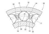
さらに、この種の保持器においては、前記柱部を、その軸方向に見て断面Y字状とした形状とすることがあるが、その場合は、その断面Y字状の上部の二股をアーチ状としてそのアーチ状二股の基部内面を円弧状として応力集中をなくする。円筒ころの転動に伴いその二股部に応力が働くが、そのアーチ状二股の基部内面がエッジ状となっていると、そのエッジに応力集中が生じてその二股部の破損を招きやすいからである。 Furthermore, in this type of cage, the column portion may have a Y-shaped cross section when viewed in the axial direction. In this case, an arch is formed at the top of the Y-shaped cross section. The inner surface of the base of the arched bifurcated shape is arcuate to eliminate stress concentration. As the cylindrical roller rolls, stress acts on the bifurcated part, but if the inner surface of the base of the arched bifurcated has an edge shape, stress concentration occurs on the edge, which can easily cause damage to the bifurcated part. is there.
前記射出成型用の合成樹脂としては、一般的なものを適宜に採用すれば良いが、例えば、直鎖状ポリフェニレンサルファイド樹脂(直鎖状PPS)に3重量%以上、20重量%以下の補強繊維を含有させたものとして、最も弱い部分の疲労限:20MPa以上としたものとする。 As the synthetic resin for injection molding, a general resin may be appropriately used. For example, a reinforcing fiber having a linear polyphenylene sulfide resin (linear PPS) of 3% by weight or more and 20% by weight or less. The fatigue limit of the weakest part: 20 MPa or more.
直鎖状PPSは、分子鎖が直鎖状であるため、分子鎖間の絡み合いが容易であり、分岐状PPSと比して靭性が大きくなり、補強繊維を所要量含有させることで、さらに機械的強度を確実に向上させることができる。このとき、補強繊維の含有量を規定したのは、その含有量が20重量%を超えると柔軟性が低下し、一方、3重量%未満であると、含有させることによる補強効果が十分に発現しない恐れがあり、また、十分な耐熱性が得られないからである。
また、最も弱い部分の疲労限:20MPa以上としたのは、通常、保持器は、負荷されるラジアル荷重:0.54C(C:定格荷重)、dn(d:軸受内径寸法、n:使用回転速度(min))=54万回転において、最も弱い個所で20MPa以上を確保しなくてはならないからである。
Since linear PPS has a linear molecular chain, entanglement between the molecular chains is easy, and the toughness is greater than that of branched PPS. Strength can be improved with certainty. At this time, the content of the reinforcing fiber is specified because the flexibility is lowered when the content exceeds 20% by weight, and the reinforcing effect by the inclusion is sufficiently exhibited when the content is less than 3% by weight. This is because sufficient heat resistance cannot be obtained.
Moreover, the fatigue limit of the weakest part: 20 MPa or more is usually that the cage is loaded with radial load: 0.54 C (C: rated load), dn (d: bearing inner diameter, n: rotation used) This is because at the speed (min)) = 540,000 rpm, 20 MPa or more must be secured at the weakest point.
前記補強用繊維としては、ガラス繊維または、炭素繊維を採用することができる。ガラス繊維を含有させた場合、優れた耐熱性が得られるとともに、靭性などの機械的特性が向上する。また、炭素繊維を含有させた場合では、機械的強度が向上するとともに、熱伝導性を向上させることが可能となる。 As the reinforcing fiber, glass fiber or carbon fiber can be employed. When glass fiber is contained, excellent heat resistance is obtained, and mechanical properties such as toughness are improved. Further, when carbon fiber is contained, the mechanical strength is improved and the thermal conductivity can be improved.
前記各構成のころ軸受用保持器は、種々の使用態様に採用できるが、例えば、自動車用の動力伝達軸を回転可能に支持する軸受に用いる。このような軸受は、潤滑油に浸されるので、耐油性が求められる。特に、前記要件を満たす直鎖状PPS製の保持器は、リンや硫黄分等を多く含む潤滑油が使用される自動車のトランスミッション装置においては、その耐油性、耐薬品性が高いことから、好ましい。 The roller bearing cage having the above-described configurations can be employed in various usage modes. For example, it is used for a bearing that rotatably supports a power transmission shaft for an automobile. Since such a bearing is immersed in the lubricating oil, oil resistance is required. In particular, a linear PPS cage that satisfies the above requirements is preferable because it has high oil resistance and chemical resistance in an automobile transmission device in which lubricating oil containing a large amount of phosphorus, sulfur, and the like is used. .
以上のように、この発明の円筒ころ軸受は、パーティングラインに突起が発生しても、その突起が柱部の両側面の溝の内部に形成され、突起がころ転動面に接触せず、また仮に接触しても、円滑な摺動状態となるため、突起によってころ転動面の潤滑油が掻き取られて、油膜切れが発生することが防止される。そのため、この発明の円筒ころ軸受は、円筒ころ軸受の運転中の潤滑性能を向上させることができる。 As described above, in the cylindrical roller bearing of the present invention, even if a protrusion is generated on the parting line, the protrusion is formed in the groove on both side surfaces of the column portion, and the protrusion does not contact the roller rolling surface. Also, even if it comes into contact, a smooth sliding state is obtained, so that the lubricating oil on the roller rolling surface is scraped off by the protrusions, thereby preventing the oil film from being cut. Therefore, the cylindrical roller bearing of the present invention can improve the lubricating performance during operation of the cylindrical roller bearing.
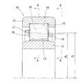
以下、この発明の実施形態を図1〜図3に示す。この実施形態の円筒ころ軸受10は、図1に示すように、内輪11と、外輪12と、この内輪11と外輪12とのそれぞれの軌道面13、14の相互間に周方向に転動可能に組み込まれる円筒ころ15と、各列の円筒ころ15を周方向に所定間隔をおいて保持する円筒ころ軸受用保持器16(以下、単に保持器16という)とから構成される。なお、前記円筒ころ軸受10は、図示するように単列円筒ころ軸受に限定されるものでなく、複列円筒ころ軸受や多列円筒ころ軸受であってもよい。
Embodiments of the present invention are shown in FIGS. As shown in FIG. 1, the
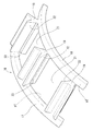
また、図4に示すように、前記保持器16は軸方向に離間した同心状の2つの円環部17、18と、両円環部17、18の間に周方向に定ピッチで設けられた複数の柱部19とからなる。
As shown in FIG. 4, the
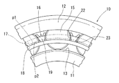
この2つの円環部17、18のうちの一方の円環部17は、図1に示すように、その内径d1が他方の円環部18の外径d2よりも大きく形成されており、この円環部17(以下、大径円環部17という)の内径面P1が、他方の円環部18(以下、小径円環部18という)の外径面P2よりも外径側に位置している(図3参照)。
As shown in FIG. 1, one of the two
この大径円環部17と小径円環部18の間および、隣接する柱部19とで囲まれた部分にポケット21が形成される。これにより、このポケット21は、保持器16の周方向の複数箇所に等間隔をもって形成され、円筒ころ15が内輪11と外輪12との間で転動する際に、円筒ころ15を保持器の周方向に等間隔に保持する。
A
前記柱部19は、図2に示すように、その軸方向に見て断面Y字状となって、その外径面の周方向両端部が、二股状外向きに突出しており、その二股状突出部分の周方向の両側面および柱部19の周方向の側面22が、円筒ころ15の外周面に沿ったアーチ状をなしている。また、前記二股状突出部分の基部内面は円弧状となっており、その基部内面に応力が集中するのが軽減される。
As shown in FIG. 2, the
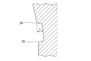
柱部19の周方向の両側面22、22には、図4に示すように、軸方向の溝23が全長にわたって設けられている。この溝23は、その両溝側面のうち、外径側の溝側面が大径円環部17の内径面P1と同一のフラット面となっており、内径側の溝側面が小径円環部18の外径面P2と同一のフラット面となっている。溝23は、図5に示すように、その側縁24がRカットされており、側縁24がエッジ状である場合に比べて、側縁24への応力集中が軽減されるので、柱部19が破断しにくい。
As shown in FIG. 4,
図5に示す溝23の最も深い部分の深さtは、図2に示す円筒ころ15の径mの10分の1以下とすると良い。溝は深いほど潤滑油を確保できるが、円筒ころの径の10分の1を超える溝の深さとすると、通常、溝形成部の柱部厚さ(軸受周方向の厚み)がその円筒ころの転動による応力に対して十分な強度を得にくくなるからである。
The depth t of the deepest portion of the
溝23の幅は、柱部19の軸方向幅の5分の1以下とすると良い。通常、対の金型を円滑に割れるようにするのは、パーティングラインを軸受の軸方向に対して最大10度位傾ける。このため、上述し、図6に示すように、溝23の幅W≧柱部19の軸方向幅L×tan10°=0.17Lから、W≧1/5L=0.2Lであれば、余裕をもって、溝23内にパーティングラインを納めることができる。
The width of the
前記保持器16は、大径円環部17の内径面P1が、小径円環部18の外径面P2よりも外径側に位置しているため、小径円環部18側から見た、大径円環部17の小径円環部18との対向面の軸方向の投影面と、大径円環部17側から見た、小径円環部18の大径円環部17との対向する面の軸方向の投影面が重ならない。
Since the inner diameter surface P1 of the large diameter
軸方向の投影面が重ならないと、従来使用していたポケット21を形成するための金型が不要となり、この保持器16は、軸受の軸方向に割れる対の金型により射出成型し得る。これにより、保持器16の製造コストを抑えることができ、これに伴い、円筒ころ軸受10の製造コストも抑えることが可能となる。
If the projection surfaces in the axial direction do not overlap, the conventionally used mold for forming the
前記構成の保持器16は、直鎖状ポリフェニレンサルファイド樹脂(PPS)に、補強用繊維材としてのガラス繊維(グラスファイバ(GF))を含有させた合成樹脂を射出成型して形成される。この直鎖状ポリフェニレンサルファイド樹脂(PPS)は、重合段階で直鎖状に分子鎖を高分子量にまで生長させたものである(特開昭61−7332号、および特開昭61−66720号公報参照)。
The
前記ガラス繊維は、前記の直鎖状PPS樹脂の重量に対して3重量%以上、20重量%以下の割合で含有させる。ガラス繊維を含有させた直鎖状PPS樹脂を射出樹脂として保持器16を射出成型により成型すると、その保持器16は、靭性等の機械的特性が向上するとともに、耐熱性、耐油性が向上する。なお、ガラス繊維(グラスファイバ(GF))の代わりに、炭素繊維(カーボンファイバ(CF))を含有させても良い。この場合、保持器16の熱伝導性をも向上させることができるので、円筒ころ軸受10の運転によって保持器16に蓄積する熱を効果的に放熱することができる。
The glass fiber is contained in a proportion of 3% by weight to 20% by weight with respect to the weight of the linear PPS resin. When the
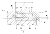
この保持器16は、前述のように軸方向に割れる2つの金型を用いて、すなわち軸方向に割れる雄金型31および雌金型32を用いて、直鎖状PPS樹脂にガラス繊維を含有させた射出樹脂を射出成型することにより形成される。雄金型31は、円柱状をなし一端部にフランジを有する形状をなし、雌金型32は、有底の円筒状に形成される。この雄金型31を雌金型32に円筒ころ軸受10の軸受の軸方向に嵌め合わせると、保持器16を成型するためのキャビティ40が形成される(図6参照)。
This
このキャビティ40は、保持器16の大径円環部17を成型するための大径円環部用キャビティ41と、小径円環部18を成型するための小径円環部用キャビティ42と、柱部19を成型するための柱部用キャビティ43とを有する。
The
大径円環部用キャビティ41は、雄金型31のフランジに設けられた軸方向の凹部33に、雌金型32の一端面に形成された軸方向の突出部34を嵌合することにより形成される。小径円環部用キャビティ42は、雄金型31の軸方向の他端部に設けられた段部35を形成する壁面と、雌金型32の内壁面とにより形成される。柱部用キャビティ43は、図7に示すように、雄金型31、雌金型32のそれぞれに設けられた径方向の凹部36、37を、雄金型31と雌金型32の合わせ面30を挟んで対向させることにより形成される。
The large-diameter
前記合わせ面30は、雄金型31と雌金型32とを組み合わせた状態において、大径円環部用キャビティ41の内径面(大径円環部17の内径面に対応した面)および小径円環部用キャビティ42の外径面(小径円環部18の外径面に対応した面)に面一でもって連続する。このため、雄金型31の円状合わせ面30が凹部33から段部35に向かって縮径するように傾斜し、雌金型32の合わせ面30が、前記突出部34から小径円環部用キャビティ42を形成する前記内壁面に向かって拡径するように傾斜する。
In the state where the
この凹部36の開口縁の両側部には、互いに向かい合う突条38が成型空間43の全長にわたって設けられる。凹部37の開口縁の両側にも、前記凹部36と同様、互いに向かい合う突条39が設けられる。
On both sides of the opening edge of the
この突条38、39は、雄金型31と雌金型32とを組み合わせた状態において、その突条38と突条39の径方向の幅を合わせた幅が、図6に示すように、成型空間43の全長にわたって所定幅wとなっている。すなわち、突条38(突条39)は、その径方向の幅が成型空間41から成型空間42に向かって小さく(大きく)なっている。この両突条38、39によって、後述のように、柱部19のポケット21の軸受周方向内側面に、その柱部19の軸方向全長に亘る直線状の溝23が形成される。
As shown in FIG. 6, the
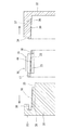
このように構成される雄金型31および雌金型32は、互いに組み合わされた状態から軸方向に割ることが可能となる。図6に示すキャビティ40に、射出樹脂としての直鎖状PPS樹脂をゲート(図示省略)から供給し、樹脂の硬化後、雄金型31を雌金型32から軸方向に抜くと、保持器16が射出成型される(図8参照)。
The
この成型された保持器16は、雄、雌金型31、32の突条38、39によって各柱部19の両側面に溝23が形成され、その溝23内面には、図7に示す鎖線のように、雄雌金型31、32の合わせ面30に対応するパーティングラインの突起44が生じる。
このとき、そのパーティングライン上の突起44は、金型31、32の使用につれてその端縁が徐々に摩耗等して徐々に大きくなる。このため、その突起44が溝23から突出しない金型31、32の使用回数とする。
In the molded
At this time, the
この発明の効果を確認するために、本発明者が行った試験について説明する。
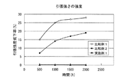
この試験は、保持器に使用される樹脂からダンベル試験片を製作し、これを潤滑油に浸漬し、引張強度を測定する。浸漬前の引張強度を基準として500時間ごとの強度の劣化の有無を確認した。
In order to confirm the effect of the present invention, a test conducted by the present inventor will be described.
In this test, a dumbbell test piece is manufactured from a resin used for a cage, and the test piece is immersed in a lubricating oil and measured for tensile strength. The presence or absence of strength deterioration every 500 hours was confirmed based on the tensile strength before immersion.
(試験体)
実施例1:PSS樹脂 大日本インキ化学工業社製 商品名『Z230』:商品名『Z200−5E』=3:1の混合樹脂+ガラス繊維7.5重量%、以下「実施例1」と略称する。
比較例1:PA66樹脂 BASF社(株)製、商品名『A3HG5』+ガラス繊維25重量%、以下「比較例1」と略称する。
比較例2:PA46樹脂 DMS JSRエンプラ(株)社製、商品名『TW200F5』+ガラス繊維25重量%、以下「比較例2」と略称する。
ガラス繊維:日東紡ガラス製、繊維径:11μm、平均繊維長:3mm
(Test specimen)
Example 1: PSS resin Product name “Z230” manufactured by Dainippon Ink & Chemicals, Inc .: Trade name “Z200-5E” = 3: 1 mixed resin + 7.5% by weight of glass fiber, hereinafter abbreviated as “Example 1” To do.
Comparative Example 1: PA66 resin, manufactured by BASF Corporation, trade name “A3HG5” + 25% by weight of glass fiber, hereinafter abbreviated as “Comparative Example 1”.
Comparative Example 2: PA46 Resin DMS JSR Engineering Plastics Co., Ltd., trade name “TW200F5” +
Glass fiber: Nittobo Glass, fiber diameter: 11 μm, average fiber length: 3 mm
(試験方法)JIS K7161
潤滑油中に浸漬した試験体を、150℃に設定した熱風循環式高温槽内に放置し、500時間毎に引張強度を測定する。
潤滑油:三菱扶桑スーパーハイポイドギアオイル、商品名『SAE90 GL−5』
(Test method) JIS K7161
The specimen immersed in the lubricating oil is left in a hot air circulation high temperature bath set at 150 ° C., and the tensile strength is measured every 500 hours.
Lubricant: Mitsubishi Fuso Super Hypoid Gear Oil, trade name “SAE90 GL-5”
実施例および比較例の試験結果を図9に示す。
図8に示すように、「実施例1」は、2000時間経過しても、引張強度の劣化が認められなかった。一方、「比較例1」、「比較例2」では、時間の経過とともに引張強度の劣化が認められた。この結果より、「実施例1」は、「比較例1」および「比較例2」と比して耐油性、耐熱性が優れており、時間経過に伴う引張強度の劣化が認められないため、長期にわたって円筒ころ軸受に使用することが可能である。
The test results of Examples and Comparative Examples are shown in FIG.
As shown in FIG. 8, “Example 1” showed no deterioration in tensile strength even after 2000 hours. On the other hand, in “Comparative Example 1” and “Comparative Example 2”, deterioration of the tensile strength was observed with time. From this result, “Example 1” is superior in oil resistance and heat resistance as compared to “Comparative Example 1” and “Comparative Example 2”, and no deterioration in tensile strength over time is observed. It can be used for cylindrical roller bearings for a long time.
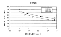
また、PPS樹脂にガラス繊維を含有させた樹脂を射出成型した保持器の疲労特性を、繰り返し応力に基づいて、ガラス繊維の含有率毎に調べる試験を行った。
この試験に先立って保持器に発生する応力を、円筒ころ軸受の実操業に基づいて下記の運転条件下での解析により調査した。
(運転条件)
ラジアル荷重:0.54C(基本静定格荷重:C)、dn値:54万
Moreover, the test which investigates the fatigue characteristic of the cage which injection-molded the resin which made the PPS resin contain the glass fiber for every content rate of glass fiber based on repeated stress was done.
Prior to this test, the stress generated in the cage was investigated by analysis under the following operating conditions based on the actual operation of the cylindrical roller bearing.
(Operating conditions)
Radial load: 0.54C (basic static load rating: C), dn value: 540,000
前記解析の結果、保持器に発生する応力は、保持器の最も強度の低い部位では20MPaとなった。これにより、実操業時、保持器を長期間使用するために、保持器に発生する疲労限を20MPa以上に確保する必要があることがわかった。 As a result of the analysis, the stress generated in the cage was 20 MPa at the lowest strength portion of the cage. Thereby, in order to use a cage for a long time at the time of actual operation, it turned out that it is necessary to ensure the fatigue limit which generate | occur | produces in a cage to 20 Mpa or more.
次に、下記の試験装置、試験条件で、保持器の疲労特性を繰り返し応力に基づいて、PPS樹脂のガラス繊維の含有率毎に調査する試験を行った。
(試験条件)応力負荷速度: 1500cpm(cycle per minute)
(試験方法)JIS K7119
(疲労寿命判定基準)T.P.の破断または振幅16mm以上
(試験体)
実施例1:PPS樹脂 大日本インキ化学工業社製 商品名『Z230』:商品名『Z200−5E』=3:1の混合樹脂(ガラス繊維7.5重量%)、以下「実施例1」と略称する。
実施例2:PSS樹脂 大日本インキ化学工業社製 商品名『Z230』:商品名『Z200−5E』=2:1の混合樹脂(ガラス繊維15重量%)、以下「実施例2」と略称する。
図10に示すように、実施例1、2は、何れも疲労限が20MPaを超えるため、優れた疲労特性を示し、この結果、実施例1、2を射出樹脂として使用した保持器16は、耐熱性、耐油性を確保しつつ、機械的強度を向上させたものとなる。
Next, the test which investigates the fatigue characteristic of a cage | basket for every content rate of the glass fiber of a PPS resin based on the repeated stress was done with the following test apparatus and test conditions.
(Test conditions) Stress load rate: 1500cpm (cycle per minute)
(Test method) JIS K7119
(Fatigue life criteria) TP breakage or amplitude 16mm or more (Test specimen)
Example 1: PPS resin Dainippon Ink & Chemicals, Inc. trade name “Z230”: trade name “Z200-5E” = 3: 1 mixed resin (7.5% by weight of glass fiber), hereinafter referred to as “Example 1” Abbreviated.
Example 2: PSS resin Dainippon Ink & Chemicals, Inc. trade name “Z230”: trade name “Z200-5E” = 2: 1 mixed resin (
As shown in FIG. 10, Examples 1 and 2 both show excellent fatigue characteristics because the fatigue limit exceeds 20 MPa. As a result, the
10 円筒ころ軸受
11 内輪
12 外輪
13 軌道面
14 軌道面
15 円筒ころ
16 保持器
17 大径円環部
18 小径円環部
19 柱部
21 ポケット
22 側面
23 溝
24 側縁
30 合わせ面
31 雄金型
32 雌金型
33、36、37 凹部
34 突出部
35 段部
38、39 突条
40 キャビティ
41 大径円環部用キャビティ
42 小径円環部用キャビティ
43 柱部用キャビティ
44 パーティングラインの突起
DESCRIPTION OF
Claims (6)
前記柱部(19)の前記ポケット(21)の軸受周方向内側面に、その柱部(19)の軸方向全長に亘る直線状の溝(23)が設けられ、その溝(23)の両溝側面のうち、外径側の溝側面が前記一方の円環部(17)の内径面(P1)と同一のフラット面とされ、内径側の溝側面が前記他方の円環部(18)の外径面(P2)と同一のフラット面とされ、前記溝(23)の幅内に前記対の金型の傾斜状のパーティングライン(30)が形成されて、そのパーティングラインの突起(44)が前記溝(23)内で収容されるようにし、前記溝(23)の側縁(24)がRカットされていることを特徴とする円筒ころ軸受用保持器。 A plurality of column portions (19) are provided between two annular portions (17, 18) of the same axial center in the circumferential direction of the annular portion, and a cylinder is formed between each of the adjacent column portions (19). It consists of a molded product of synthetic resin in which a pocket (21) for accommodating the rollers (15) is formed, and one of the two annular parts (17, 18) has an annular part (17) in the bearing radial direction. The cylindrical roller is injection-molded by a pair of molds whose inner diameter surface (P1) is positioned on the outer diameter side with respect to the outer diameter surface (P2) of the other annular portion (18) and is split in the axial direction of the bearing. In bearing cages,
A linear groove (23) is provided on the inner surface in the bearing circumferential direction of the pocket (21) of the column part (19) over the entire axial length of the column part (19), and both of the grooves (23) are provided. Of the groove side surfaces, the groove side surface on the outer diameter side is the same flat surface as the inner diameter surface (P1) of the one annular portion (17), and the groove side surface on the inner diameter side is the other annular portion (18). The outer surface (P2) is the same flat surface, and the paired mold inclined parting lines (30) are formed within the width of the groove (23). (44) is accommodated in the groove (23), and the side edge (24) of the groove (23) is R-cut .
Priority Applications (1)
| Application Number | Priority Date | Filing Date | Title |
|---|---|---|---|
| JP2008073828A JP5154986B2 (en) | 2008-03-21 | 2008-03-21 | Retainer for cylindrical roller bearing |
Applications Claiming Priority (1)
| Application Number | Priority Date | Filing Date | Title |
|---|---|---|---|
| JP2008073828A JP5154986B2 (en) | 2008-03-21 | 2008-03-21 | Retainer for cylindrical roller bearing |
Publications (2)
| Publication Number | Publication Date |
|---|---|
| JP2009228752A JP2009228752A (en) | 2009-10-08 |
| JP5154986B2 true JP5154986B2 (en) | 2013-02-27 |
Family
ID=41244390
Family Applications (1)
| Application Number | Title | Priority Date | Filing Date |
|---|---|---|---|
| JP2008073828A Expired - Fee Related JP5154986B2 (en) | 2008-03-21 | 2008-03-21 | Retainer for cylindrical roller bearing |
Country Status (1)
| Country | Link |
|---|---|
| JP (1) | JP5154986B2 (en) |
Families Citing this family (6)
| Publication number | Priority date | Publication date | Assignee | Title |
|---|---|---|---|---|
| JP2013241959A (en) * | 2012-05-18 | 2013-12-05 | Jtekt Corp | Split cage for rolling bearing |
| FR3018570B1 (en) * | 2014-03-14 | 2017-02-24 | Ntn-Snr Roulements | MONOBLOC PLASTIC CAGE FOR ROLLER BEARING. |
| JP2019065919A (en) * | 2017-09-29 | 2019-04-25 | Ntn株式会社 | Retainer |
| DE102018126032A1 (en) * | 2018-10-19 | 2020-04-23 | Haldex Brake Products Ab | Method for producing a bearing cage for a disc brake, molded part therefor and bearing cage |
| JP7186580B2 (en) * | 2018-10-31 | 2022-12-09 | 日本トムソン株式会社 | slewing bearing |
| DE102021117246A1 (en) * | 2021-07-05 | 2023-01-05 | Schaeffler Technologies AG & Co. KG | roller bearing cage |
Family Cites Families (9)
| Publication number | Priority date | Publication date | Assignee | Title |
|---|---|---|---|---|
| JPS608525A (en) * | 1983-06-28 | 1985-01-17 | Koyo Seiko Co Ltd | Synthetic resin retainer for cylindrical roller bearing |
| JPS62117322U (en) * | 1985-09-13 | 1987-07-25 | ||
| JP2628674B2 (en) * | 1987-06-04 | 1997-07-09 | 日本精工株式会社 | Plastic cage for bearing |
| JPH08145062A (en) * | 1994-11-18 | 1996-06-04 | Koyo Seiko Co Ltd | Holder made of synthetic resin |
| JPH1151061A (en) * | 1996-12-27 | 1999-02-23 | Nippon Seiko Kk | Synthetic resin cage for roller bearings |
| JP2001012477A (en) * | 1999-04-28 | 2001-01-16 | Nsk Ltd | Cage for rolling bearing |
| JP2004076747A (en) * | 2002-08-09 | 2004-03-11 | Nsk Ltd | Roller bearing cage and rolling bearing |
| JP2005069282A (en) * | 2003-08-20 | 2005-03-17 | Ntn Corp | Cylindrical roller bearing |
| JP4896510B2 (en) * | 2005-12-16 | 2012-03-14 | Ntn株式会社 | Roller bearing |
-
2008
- 2008-03-21 JP JP2008073828A patent/JP5154986B2/en not_active Expired - Fee Related
Also Published As
| Publication number | Publication date |
|---|---|
| JP2009228752A (en) | 2009-10-08 |
Similar Documents
| Publication | Publication Date | Title |
|---|---|---|
| JP5154986B2 (en) | Retainer for cylindrical roller bearing | |
| JP5870563B2 (en) | Roller bearing cage and rolling bearing | |
| KR102544828B1 (en) | tapered roller bearings | |
| US10605303B2 (en) | Cylindrical roller bearing | |
| WO2014163177A1 (en) | Tapered roller bearing-use resin made cage and tapered roller bearing provided with such cage | |
| JPWO2012023437A1 (en) | Rolling bearings and spindles for machine tools | |
| TWI708021B (en) | Cylindrical roller bearing | |
| WO1996024778A1 (en) | Roller with cage | |
| TW201819787A (en) | Retainer and rolling bearing with same | |
| JP5360526B2 (en) | Retainer for cylindrical roller bearing | |
| JP2014101946A (en) | Rolling bearing | |
| WO2019065768A1 (en) | Retainer for tapered roller bearing, and tapered roller bearing | |
| JP2005069282A (en) | Cylindrical roller bearing | |
| WO2013084724A1 (en) | Rolling bearing | |
| JP2016102514A (en) | Rolling bearing | |
| JP2008014335A (en) | Tapered roller bearing | |
| WO2022186094A1 (en) | Rolling bearing and cage for rolling bearing | |
| JP2007057038A (en) | Conical roller bearing | |
| JP2016070485A (en) | Holder for ball bearing | |
| JP2007292093A (en) | Deep groove ball bearing | |
| WO2013042703A1 (en) | Roller bearing | |
| JP2007100909A (en) | Roller bearing | |
| JP2006161882A (en) | Rolling bearing cage | |
| JP2013068282A (en) | Roller bearing | |
| JP2007002973A (en) | Thrust roller bearing and method for manufacturing cage for thrust roller bearing |
Legal Events
| Date | Code | Title | Description |
|---|---|---|---|
| A621 | Written request for application examination |
Free format text: JAPANESE INTERMEDIATE CODE: A621 Effective date: 20110228 |
|
| A977 | Report on retrieval |
Free format text: JAPANESE INTERMEDIATE CODE: A971007 Effective date: 20120224 |
|
| A131 | Notification of reasons for refusal |
Free format text: JAPANESE INTERMEDIATE CODE: A131 Effective date: 20120306 |
|
| A521 | Written amendment |
Free format text: JAPANESE INTERMEDIATE CODE: A523 Effective date: 20120501 |
|
| TRDD | Decision of grant or rejection written | ||
| A01 | Written decision to grant a patent or to grant a registration (utility model) |
Free format text: JAPANESE INTERMEDIATE CODE: A01 Effective date: 20121120 |
|
| A61 | First payment of annual fees (during grant procedure) |
Free format text: JAPANESE INTERMEDIATE CODE: A61 Effective date: 20121206 |
|
| FPAY | Renewal fee payment (event date is renewal date of database) |
Free format text: PAYMENT UNTIL: 20151214 Year of fee payment: 3 |
|
| R150 | Certificate of patent (=grant) or registration of utility model |
Free format text: JAPANESE INTERMEDIATE CODE: R150 |
|
| LAPS | Cancellation because of no payment of annual fees |