JP5154936B2 - Method and apparatus for generating a reference pressure in a chamber of a capacitive sensor - Google Patents
Method and apparatus for generating a reference pressure in a chamber of a capacitive sensor Download PDFInfo
- Publication number
- JP5154936B2 JP5154936B2 JP2007535717A JP2007535717A JP5154936B2 JP 5154936 B2 JP5154936 B2 JP 5154936B2 JP 2007535717 A JP2007535717 A JP 2007535717A JP 2007535717 A JP2007535717 A JP 2007535717A JP 5154936 B2 JP5154936 B2 JP 5154936B2
- Authority
- JP
- Japan
- Prior art keywords
- pressure
- vacuum
- housing
- chamber
- opening
- Prior art date
- Legal status (The legal status is an assumption and is not a legal conclusion. Google has not performed a legal analysis and makes no representation as to the accuracy of the status listed.)
- Expired - Fee Related
Links
Images


Classifications
-
- G—PHYSICS
- G01—MEASURING; TESTING
- G01L—MEASURING FORCE, STRESS, TORQUE, WORK, MECHANICAL POWER, MECHANICAL EFFICIENCY, OR FLUID PRESSURE
- G01L9/00—Measuring steady of quasi-steady pressure of fluid or fluent solid material by electric or magnetic pressure-sensitive elements; Transmitting or indicating the displacement of mechanical pressure-sensitive elements, used to measure the steady or quasi-steady pressure of a fluid or fluent solid material, by electric or magnetic means
- G01L9/0041—Transmitting or indicating the displacement of flexible diaphragms
- G01L9/0072—Transmitting or indicating the displacement of flexible diaphragms using variations in capacitance
-
- G—PHYSICS
- G01—MEASURING; TESTING
- G01L—MEASURING FORCE, STRESS, TORQUE, WORK, MECHANICAL POWER, MECHANICAL EFFICIENCY, OR FLUID PRESSURE
- G01L9/00—Measuring steady of quasi-steady pressure of fluid or fluent solid material by electric or magnetic pressure-sensitive elements; Transmitting or indicating the displacement of mechanical pressure-sensitive elements, used to measure the steady or quasi-steady pressure of a fluid or fluent solid material, by electric or magnetic means
- G01L9/12—Measuring steady of quasi-steady pressure of fluid or fluent solid material by electric or magnetic pressure-sensitive elements; Transmitting or indicating the displacement of mechanical pressure-sensitive elements, used to measure the steady or quasi-steady pressure of a fluid or fluent solid material, by electric or magnetic means by making use of variations in capacitance, i.e. electric circuits therefor
Landscapes
- Physics & Mathematics (AREA)
- General Physics & Mathematics (AREA)
- Measuring Fluid Pressure (AREA)
Description
本発明は、容量型圧力変換器に関する。より詳細には、本発明は、容量型圧力変換器アセンブリのチャンバ内に基準圧力を生成するための、改良された方法および装置に関する。 The present invention relates to a capacitive pressure transducer. More particularly, the present invention relates to an improved method and apparatus for generating a reference pressure in a chamber of a capacitive pressure transducer assembly.
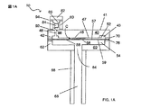
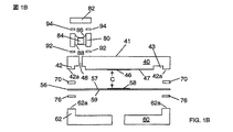
図1Aは、組み立て後の従来の容量型圧力変換器アセンブリ10の断面図を示す。図1Bは、図1Aの上部筐体40とダイヤフラム56と下部筐体60の分解組立図である。簡単に言えば、容量型圧力変換器アセンブリ10は、内部空洞を形成する本体を含んでいる。比較的薄く、柔軟性のあるセラミックダイヤフラム56によって、内部空洞が第1封止内部チャンバ52と第2封止内部チャンバ54とに分割されている。以下に詳細に述べるとおり、ダイヤフラム56は、チャンバ52、54の圧力差に応じて、ダイヤフラム56が湾曲、移動または変形するように取り付けられている。変換器アセンブリ10は、ダイヤフラムの湾曲度を表すパラメータを提供し、したがってこのパラメータは、チャンバ52、54間の圧力差を間接的に表す。圧力差を表す、変換器アセンブリ10によって提供されるパラメータは、ダイヤフラム56と、上部筐体40に配置された1つまたは複数の導体との間の静電容量である。
FIG. 1A shows a cross-sectional view of a conventional capacitive
容量型圧力変換器アセンブリ10は、セラミックの上部筐体40とセラミックの下部筐体60とを含んでいる。上部筐体40は、一般に、上から見ると円筒形をしており、上面41と、中心下面47と、下面42aを有する環状肩部42と、中心下面47と環状肩部42との間に位置する環状チャネル43とを形成している。環状肩部42の下面42aは、中心下面47と実質的に同一平面上にある。上部筐体は、さらに、上側から下側に筐体40を貫通して延びる開口(または通路)48を形成している。金属導体46が下面47の中央部上に配置されている。
The capacitive
ダイヤフラム56は、一般に、上面57と、反対側の下面59とを有する円形の薄いダイヤフラムである。金属導体58が、ダイヤフラム56の上面57の中央部に配置されている。ダイヤフラム56と上部筐体40とは、上部筐体40の導体46がダイヤフラム56の導体58と対向して置かれるように配置されている。ダイヤフラム56は、高温気密シール(またはジョイント)70によって上部筐体40に結合されている。シール70は、上部筐体40の環状肩部42の下面42aと、ダイヤフラム56の面57の対応する環状部分との間に位置している。封止されると、上部筐体40、シール70およびダイヤフラム56によって、基準チャンバ52が形成される。基準圧力が生成され、基準チャンバ52内で維持される。開口48が、基準チャンバ52への入口または入口路を提供する。
The
一般には円形形状の下部筐体60は、中心開口64と、上面62aを有する上向きに突出した環状肩部62とを形成している。下部筐体60の肩部62の上面62aは、高温気密シール(またはジョイント)76によってダイヤフラム56の下面59の対応する部分と結合されている。シール76は、シール70と同様の方法で置かれ、組み込むことができる。封止されると、下部筐体60とシール76とダイヤフラム56の面59によって、プロセスチャンバ54が形成される。
The generally circular
入口通路68を有する圧力管66は、例えば、入口通路68が下部筐体60の開口64と位置合わせされるように、シールによって下部筐体60に結合される。したがって、プロセスチャンバ54は、開口64と入口通路68とを介して、外部環境と流体連通される。作動中、容量型圧力変換器アセンブリ10は、この外部環境の圧力を測定する。
The
容量型圧力変換器アセンブリ10の導体46、58は、可変コンデンサCの平行板を形成する。周知のように、C=Aεrε0/dであって、Cは2枚の平行板の間の静電容量であり、Aは平行板間の共通面積であり、ε0は真空の誘電率であり、εrは平行板を分離する材料の比誘電率であり(例えば、真空の場合εr=1)、dは平行板間の軸方向の距離(すなわち、平行板の法線に沿って測定された平行板間の距離)である。したがって、コンデンサCによって与えられる静電容量は、導体46と導体58との間の軸方向の距離の関数である。チャンバ52、54間の圧力差の変化に応じて、ダイヤフラム56が上下に移動または湾曲するため、コンデンサCによって与えられる静電容量も変化する。いずれの時点であっても、コンデンサCによって与えられる静電容量は、チャンバ52、54間の瞬時圧力差を表している。公知の電気回路(例えば、コンデンサCによって与えられる静電容量の関数である共振周波数によって特徴付けられる「タンク」回路)を用いて、コンデンサCによって与えられる静電容量を測定し、圧力差を表す電気信号を生成することができる。導体46、58は、例えば金または銅などの広範囲の導体材料から構成することができ、公知の薄膜もしくは厚膜プロセスまたは他の公知の製造方法によって製造することができる。薄膜プロセスが利用される場合、導体46、48の厚みは、例えば約1μmであってもよい。
The
ダイヤフラム56は合酸化アルミニウムから作製されることが多い。しかし、セラミックの単結晶酸化物材料など他のセラミック材料を用いてもよい。セラミック構成部品を有する静電容量センサが、米国特許第5,920,015号および第6,122,976号で開示されている。
上述のとおり、チャンバ52、54間の圧力差の変化によって、ダイヤフラム56は湾曲し、それによって導体46と導体58との間の間隙が変化する。間隙の変化を測定することによって、圧力差を測定することができる。しかし、間隙は、圧力とは無関係な要因によって影響を受けることもある。例えば、間隙は、温度変化によって影響を受ける可能性がある。変換器アセンブリ10の構成部品は、それぞれが特有の熱膨張係数を有する多種多様な材料から作製することができるため、周囲環境における温度変化によって、ダイヤフラム56は導体46に接近または離れる方向に移動する可能性がある。好都合な点は、温度変化による間隙の変化は、圧力差の変化による間隙の変化とは異なる特性を有する。周囲環境温度の変化によって生じる間隙の変化を補償するために、上部筐体40の下面47上に、導体46と隣接して配置された第2の導体(図示せず)を含むことが知られている。このような実施形態では、導体46、58は可変コンデンサC1の平行板を形成し、導体58と第2導体は可変コンデンサC2の平行板を形成する。2つのコンデンサC1、C2を公知の方法で使用して、温度変化に対する変換器の感度を低減することができる。
As described above, a change in pressure difference between the
上部筐体40は、下面47とこの上に置かれたいずれかの導体とが、チャンバ52、54内の圧力が等しいときに導体58(すなわち、ダイヤフラム56)によって形成された面と平行な面に置かれるように位置合わせされている。上述のとおり、導体46、58によって形成される静電容量は、これらの対向する導体間に存在する間隙(すなわち、軸方向の距離)に依存している。比較的小さい(例えば、0.0004インチ(10〜12μm)程度)間隙は、一部は、シール70の厚さと、上部筐体40の形状および構成(例えば、下面42aが平面から外れる量、すなわち、もしあるとすれば、下面47に対するずれ)に左右される。
The
作動においては、容量型圧力変換器アセンブリ10は、一般に、絶対圧力変換器として用いられる。この形態では、基準チャンバ52は、実質的ゼロ圧力、例えば10−8トール未満まで排気され、その後、基準チャンバ52は封止される。その後、基準圧力はベースラインとなり、このベースラインからプロセスチャンバ54内の圧力が決定される。基準チャンバ52内を実質的ゼロ圧力で維持するために、変換器アセンブリ10は、チューブ80とカバー82と保持ワイヤ86とスクリーン88とゲッター素子84とを含んでいる。図1Aおよび図1Bに示されるとおり、スクリーン88は、チューブ80の中空部分内でゲッター素子84を支持し、一方、保持ワイヤ86はゲッター素子84をスクリーン88に押し付けて保持している。チューブ80の中空部分は、上部筐体40の開口48の上方に置かれ、これによりゲッター素子84は基準チャンバ52と流体連通する。スクリーン88はさらに、ゲッター素子84を支持することに加えて、ダイヤフラム56の作動に悪影響を与える粒子が基準チャンバ52内に通過することを防いでいる。
In operation, the capacitive
チューブ80の底端部は、高温気密シール92によって開口48回りで上部筐体40の上面41に結合されている。一方、カバー82は、低温気密シール94によってチューブ80の上端部に結合されている。シール92、94および上部筐体40の肩部42とダイヤフラム56との間に位置するシール70は全て、基準チャンバ52内に生成される基準圧力の維持を支援している。高温シール92は高温のガラス材料で構成され、一方低温シール94は低温ガラス材料で構成されている。高温シール92を形成するために、高温のガラス材料が、チューブ80の底端部、面41の対応する封止領域またはこの両方の上に付着される。高温のガラス材料が融解され、上部筐体40の上面41に垂直な力がチューブ80と上部筐体40との間に加わり、その後、高温のガラス材料が冷却され(すなわち凝固され)て、高温気密シール92が形成される。低温シール94は、同様に、チューブ80の上端部と、カバー82の対応する封止領域との間に形成される。高温シール92の高温ガラス材料の融解温度は、低温シール94の低温ガラス材料の融解温度よりも高い。異なる融解温度を得るために、シール92、94のガラス材料は異なる材料から構成されるか、または共通の材料で量が異なっていてもよい。高温シール92の融解温度は、高温シール70、76の融解温度よりも高く、高温シール70、76の融解温度は、低温シール94の融解温度よりも高い。
The bottom end portion of the
ゲッター素子84は、活性化されると、封止された基準チャンバ52内に存在するあらゆる気体不純物も効果的に吸収するように作用する材料から構成されている。したがって、活性化すると、ゲッター素子84は、長時間(例えば、10年間以上)、基準圧力を超高真空レベルで維持するのに役立つ。
The
超高真空圧、すなわち実質的ゼロ圧力は、好都合で有用な基準圧力であるが、他の基準圧力を用いることもできる。基準圧力がチャンバ52内に生成された後、圧力チューブ66を流体源(図示せず)に接続して、この流体の圧力を測定することができる。このように圧力チューブ66を結合することにより、圧力が測定される流体をプロセスチャンバ54(およびダイヤフラム56の下面59)に送る。ダイヤフラム56の中心が、チャンバ52、54間の圧力差に応じて上下に移動または湾曲し、これによってコンデンサCの静電容量が変化する。コンデンサCの瞬時静電容量はダイヤフラム56の位置を表すため、変換器アセンブリ10は、チャンバ52内に生成された基準圧力を基準にしたチャンバ54内の圧力を測定することができる。
Ultra-high vacuum pressure, or substantially zero pressure, is a convenient and useful reference pressure, but other reference pressures can be used. After the reference pressure is generated in the
容量型圧力変換器アセンブリ10の精度は、基準チャンバ52内の基準圧力を生成および維持できる精度に依存する。言い換えると、基準チャンバ52内の実際の圧力が意図および設計された基準圧力からずれると、容量型圧力変換器アセンブリ10の性能はそれに応じて低下する。
The accuracy of the capacitive
基準チャンバ52内の基準圧力を生成することと、ゲッター素子84を活性化することと、チューブ80に対してカバー82を封止することとの各ステップは、一般的には、容量型圧力変換器アセンブリ10を製造する際に実行される最後の数ステップである。したがって、上部筐体40を高温シール70でダイヤフラム56に結合することと、下部筐体60を高温シール76でダイヤフラム56に結合することと、圧力チューブ66を開口64回りで下部筐体60に結合することと、および(スクリーン88、ゲッター素子84および保持ワイヤ86を有する)チューブ80を、高温シール92で開口48回りの上部筐体40の面41に結合することとの各ステップは、通常、基準圧力が生成される前にすでに完了されているはずである。
The steps of generating a reference pressure within the
基準チャンバ52内に基準圧力を生成するために、基準チャンバ52は、典型的には、バーンアウトおよび排気プロセスを受け、その後、カバー82がチューブ80に対して封止される。基準チャンバ52は、基準チャンバ52を形成する内側面(基準チャンバ52と流体連通されるカバー82、チューブ80、筐体40の面を含む)を加熱することによって「バーンアウト」され、チャンバ52は、基準チャンバ52を超高真空で吸引することによって「排気」される。バーンアウト熱によって、これらの内側面に存在し得る、揮発物や水分といった汚染物質が蒸発する。一方、排気真空は蒸発した汚染物質と気体とを基準チャンバ52から外部に吸引する。カバー82はチューブ80にまだ封止されていないため、汚染物質と気体とは基準チャンバ52と開口48とチューブ80の中空部分とから外に吸引される。バーンアウトおよび排気プロセスが完了し、真空圧が維持されている間に、カバー82は低温シール94でチューブ80に封止されて、基準チャンバ52内に基準圧力を生成する。
In order to generate a reference pressure within the
図2Aおよび図2Bは、容量型圧力変換器アセンブリ10の基準チャンバ52内に基準圧力を生成するために用いられる、従来の方法および装置を示している。図2Aは、バーンアウトおよび排気プロセス全体を示している。一方、図2Bは、カバー82がチューブ80の上端部上で封止されるプロセス全体を示している。装置は、内部真空チャンバ95を形成する真空筐体93を含んでいる。図2Aを参照すると、低温封止材料94aが、チューブ80の上端部上に置かれる。半完成品の変換器アセンブリ10、すなわちカバー82がチューブ80にまだ封止されていない変換器アセンブリが、その後、真空チャンバ95内に置かれる。[明瞭化のために、圧力チューブ66は図2A、図2Bおよびそれ以降の他の図面のいくつかから省略されている。ただし、圧力チューブ66は、一般には、アセンブリが真空チャンバ95内に置かれる前には下部筐体60に結合されている。]変換器アセンブリ10が真空チャンバ95内に置かれた後、真空筐体93はオーブン(図示せず)内に置かれ、真空源(図示せず)が真空チャンバ95に結合され、基準チャンバ52のバーンアウトおよび排気プロセスが開始される。20時間以上続く可能性があるバーンアウトおよび排気プロセスの間、変換器アセンブリ10は約250℃の温度まで加熱され、10−8トール(またはそれ未満)程度の超高真空圧が真空チャンバ95内に生成される。図2Aにおいて、基準チャンバ52(および開口48とチューブ80)のバーンアウトおよび排気は、基準チャンバ52から開口48を通過して上方に、チューブ80の先端部を通過して上方に延びる矢印によって示されている。
2A and 2B illustrate a conventional method and apparatus used to generate a reference pressure in the
基準チャンバ52のバーンアウトおよび排気が完了した後、カバー82は低温シール94によってチューブ80に結合される。カバー82は、基準チャンバ52内の真空を保つために、真空筐体93を開けずに、チューブ80に取り付けられ、封止される。したがって、図2Aにおいて見られるように、バーンアウトおよび排気プロセスが開始される前に、カバー82は、真空筐体93の真空チャンバ95内に貫通するロッド96の端部に取り付けられる。バーンアウトおよび排気プロセスが完了すると、ロッド96を動かすことにより、カバー82が、チューブ80の上端部に配置された低温封止材料94aと接触するようにすることができる。
After the burnout and evacuation of the
低温シール94を形成する低温封止材料94aは、バーンアウトおよび排気プロセス中には融解しない。すなわち、バーンアウト温度は、一般に、低温封止材料94aの融解温度以下に設定される。さらに、バーンアウトおよび排気プロセスは、変換器アセンブリ10内ですでに形成されたシール(例えば、高温シール70、76、92)に損傷を与えてはならない。したがって、バーンアウト温度はこれらのシールの融解温度を超えてはならない。
The low
高温運動用シール99(例えば、ガスケット)が、真空筐体93の、ロッド96が真空筐体93を貫通する場所に置かれる。高温運動用シール99は、ロッドを自由に上下運動できるようにすると同時に、真空筐体93の真空チャンバ95内に存在する圧力を維持する役割を果たす。
A high temperature motion seal 99 (eg, gasket) is placed on the
バーンアウトおよび排気プロセスを開始する前に、カバー82が、低温シール98によってロッド96の端部に取り付けられる。低温シール98の融解温度(すなわち融点)は、低温封止材料94aの融解温度よりも低く、バーンアウト温度よりも高いため、バーンアウトおよび排気プロセス中には融解しない。ロッド96は、高温運動用シール99を貫通して延び、カバー82と共に、変換器アセンブリ10のチューブ80に位置合わせされる。
Prior to initiating the burnout and evacuation process, a
次に図2Bを参照すると、バーンアウトおよび排気プロセスが完了した後、真空チャンバ95内の圧力が維持される間に、ロッド96/カバー82は、カバー82が低温封止材料94aと接触するまで下げられる。その後、真空チャンバ95内の温度が上昇する(オーブンの指示のとおりに)ことによって、低温封止材料94aが融解する。また、この温度上昇によって、低温シール98が融解し、ゲッター素子84を活性化させる。カバー82とチューブ80との間で低温気密シール94を形成するために、真空チャンバ95内の温度は、低温封止材料94aが凝固するまで低下する。一方で、低温シール98が十分に融解し、ロッド96が引っ張られて変換器アセンブリ10から離される。低温シール94が形成されると(したがって基準チャンバ52内の基準圧力が生成されると)、真空チャンバ95内の温度は周囲温度まで下がり、その後、真空源が外され、組み立てられた変換器アセンブリ10が真空筐体93から取り出される。
Referring now to FIG. 2B, after the burnout and evacuation process is complete, while the pressure in the
図3は、図2Aおよび図2Bの装置および方法の、従来のバーンアウト、排気および封止プロセスを、より詳細に示している。図3では、プロセスフローのx軸は時間を表し、y軸は摂氏温度を表している。バーンアウトおよび排気プロセスを開始する前に、プロセスフローのステップAでは、カバー82が低温シール98を介してロッド96に取り付けられ、変換器アセンブリ10とカバー82とロッド96とが真空チャンバ95内に置かれている(図2A)。ステップA→Bの間、真空チャンバ95内の温度は250℃のバーンアウト温度まで上がり、圧力は10−8トールの排気圧まで下がる。ステップA→Bは3時間で終了する。バーンアウト温度と排気圧が達成された(ステップB)後、ステップB→Cで、基準チャンバ52は20時間でバーンアウトされ、排気される。ステップCに到達する直前に、ロッド96とカバー82が下げられて、カバー82がチューブ80の上端部上に配置された低温封止材料94aと接触する。バーンアウトおよび排気ステップが完了すると(ステップC)、ステップC→Dで、真空チャンバ95内の温度は475℃まで上昇し、これによって、低温封止材料94aと低温シール98とが融解する。ステップC→Dは3時間続く。その後、ステップD→Eで、真空チャンバ95は475℃で30分間維持されて、低温封止材料94aと低温シール98とが十分に融解されことを保証する。その後、ステップE→Fで、真空チャンバ95内の温度は2時間に亘って400℃まで下げられ、これによって、低温封止材料94aが凝固し、低温気密シール94が形成される。低温シール98の融点は400℃以下であり、したがって、低温シール98はステップE→Fの間、融解状態を維持する。ステップFに到達する直前に、ロッド96は持ち上げられ、カバー82から離れる(図2B)。最後に、真空チャンバ95内の温度および圧力が4時間に亘って周囲環境状態にまでされ、ステップF→Gで、組み立てられた圧力変換器アセンブリ10が、真空筐体93の真空チャンバ95から取り出される。図3で示されているとおり、従来のバーンアウト、排気および封止プロセスは、32時間半で終了することができる。
FIG. 3 illustrates in more detail the conventional burnout, evacuation and sealing process of the apparatus and method of FIGS. 2A and 2B. In FIG. 3, the x-axis of the process flow represents time and the y-axis represents temperature in degrees Celsius. Prior to initiating the burnout and evacuation process, in step A of the process flow, the
上述の方法および装置では、必ずしも確実に、正確な基準圧力が容量型圧力変換器アセンブリ10の基準チャンバ52内に生成されているとは限らない。例えば、ロッド96および高温運動用シール99を利用する真空筐体93内で、10−8トール(またはそれ未満)程度の超高真空を生成および維持することは極めて難しい。この理由は、高温運動用シール99があるために、真空筐体93の圧力の完全性が損なわれる傾向にあるためである。また、ロッド作動はめ合わせプロセスの間、カバー82とチューブ80の位置および向きを正確に制御することは難しく、また費用を要する。カバー82が、はめ合わせプロセス中に、チューブ80に対して適切に位置合わせまたは方向付けされていない場合、低温シール94の完全性が損なわれる恐れがあり、または低温シール94が完全に失敗する可能性もある。
The methods and apparatus described above do not necessarily ensure that an accurate reference pressure is generated in the
したがって、容量型圧力変換器アセンブリの基準チャンバ内の基準圧力を正確に生成する方法および装置の必要性が存在する。
本発明は、容量型圧力変換器アセンブリの基準チャンバ内の基準圧力を正確に生成する方法および装置に関する。 The present invention relates to a method and apparatus for accurately generating a reference pressure in a reference chamber of a capacitive pressure transducer assembly.
圧力変換器は、カバーと、基準チャンバと開口とを形成する筐体とを含んでいる。溶融可能な封止材料が、カバーおよび筐体のうち少なくとも1つの上に配置されている。装置は、第1位置と第2位置との間で回転可能な圧力チャンバと、開口近くで変換器に取り付け可能な案内部とを含んでいる。案内部は内部空間を形成している。ケーブルを用いて第1位置と第2位置との間で圧力チャンバを回転させることができる。アクチュエータモータとアクチュエータロッドとを交互に用いて、圧力チャンバを回転させることができる。圧力チャンバに接続された圧力源によって、圧力チャンバ内に所望の圧力を生成すると同時に、加熱器(例えばオーブン)によって圧力チャンバを十分高い温度まで選択的に加熱して、封止材料を融解することができる。 The pressure transducer includes a cover and a housing forming a reference chamber and an opening. A meltable sealing material is disposed on at least one of the cover and the housing. The apparatus includes a pressure chamber that is rotatable between a first position and a second position, and a guide that is attachable to the transducer near the opening. The guide part forms an internal space. A cable can be used to rotate the pressure chamber between the first position and the second position. The pressure chamber can be rotated using alternating actuator motors and actuator rods. A pressure source connected to the pressure chamber generates the desired pressure in the pressure chamber and at the same time selectively heats the pressure chamber to a sufficiently high temperature with a heater (eg, an oven) to melt the sealing material. Can do.
カバーが案内部の空間内に位置合わせされ、案内部が開口近くで変換器に取り付けられる。変換器、カバーおよび案内部は圧力チャンバ内に配置され、圧力チャンバが第1位置に回転し、圧力が圧力源を介して圧力チャンバ内に生成され、チャンバが加熱されて不要な材料を焼き出しする。基準圧力が基準チャンバ内に生成された後、圧力チャンバが第2位置まで回転し、第2位置では、重力でカバーが空間内の開口に向かって動く。その後、加熱器が圧力チャンバを加熱して、封止材料を融解する。冷却すると、封止材料は、変換器の基準チャンバ内の基準圧力を封止するシールを形成する。 A cover is aligned in the space of the guide and the guide is attached to the transducer near the opening. The transducer, cover and guide are located in the pressure chamber, the pressure chamber rotates to the first position, pressure is generated in the pressure chamber via the pressure source, and the chamber is heated to bake out unwanted material. To do. After the reference pressure is generated in the reference chamber, the pressure chamber rotates to the second position, where the cover moves by gravity toward the opening in the space. A heater then heats the pressure chamber to melt the sealing material. Upon cooling, the sealing material forms a seal that seals the reference pressure in the reference chamber of the transducer.
装置は、案内部の空間内に配置された、ボールなどの重量体を含んでもよい。 The apparatus may include a weight body such as a ball disposed in the space of the guide portion.
案内部と回転可能な圧力チャンバとを有する装置を利用することによって、本発明の方法および装置は、基準チャンバの封止プロセス中にカバーを正確に位置合わせし、方向を決めることができる。さらに、本発明の方法および装置は、圧力チャンバ内の圧力を維持するために高温運動用シールを用いる必要がない。 By utilizing an apparatus having a guide and a rotatable pressure chamber, the method and apparatus of the present invention can accurately align and orient the cover during the reference chamber sealing process. Furthermore, the method and apparatus of the present invention does not require the use of a hot motion seal to maintain pressure in the pressure chamber.
本発明のさまざまな目的、特徴および利点は、以下の図面と合わせて考慮する場合、本発明の以下の詳細な説明を参照して、十分に理解することができる。図面では、同様の参照符号は同様の構成要素を特定している。以下の図面は、単に例示を目的とするだけであって、本発明を限定するものではない。本発明の権利範囲は、以下の特許請求の範囲で記載されている。 Various objects, features and advantages of the present invention can be more fully understood with reference to the following detailed description of the invention when considered in conjunction with the following drawings. In the drawings, like reference numerals identify like elements. The following drawings are for illustrative purposes only and are not intended to limit the present invention. The scope of the present invention is set forth in the following claims.
本発明は、容量型圧力変換器アセンブリの基準チャンバ内に基準圧力を正確に生成する方法および装置に関する。本発明は、変換器アセンブリのバーンアウトおよび排気プロセスを容易にするために、真空チャンバ内に超高真空を生成することができ、基準チャンバの封止プロセス中に、開口カバーの送り出しおよびはめ合わせを制御することができる。さらに、本発明は高温運動用シールを用いずに、真空チャンバ内に超高真空を維持できる。 The present invention relates to a method and apparatus for accurately generating a reference pressure in a reference chamber of a capacitive pressure transducer assembly. The present invention can generate an ultra-high vacuum in the vacuum chamber to facilitate burnout and evacuation processes of the transducer assembly, and during opening and fitting of the open cover during the reference chamber sealing process. Can be controlled. Furthermore, the present invention can maintain an ultra-high vacuum in the vacuum chamber without using a high temperature motion seal.
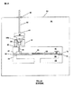
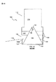
図4Aは、本発明により構成された例示的な装置100の側面図を示している。図4Bは、装置100の正面図を示している。装置100は、真空筐体110と支持アセンブリ120とから構成されている。真空筐体110は内部真空チャンバを形成し、これについては以下に詳細に説明する。バーンアウト、排気および封止される容量型圧力変換器アセンブリ10が、真空筐体110の内部真空チャンバ内に固定されている。支持アセンブリ120は、容量型圧力変換器アセンブリ10がバーンアウト、排気および封止されるとき、真空筐体110を支持し、より詳細には、真空筐体110とこの中に配置された容量型圧力変換器アセンブリ10とを、これらの処理ステップが実行されている間に、回転させることができる。
FIG. 4A shows a side view of an
真空筐体110は、金属下部フランジ112と金属上部筐体114とを含んでいる。真空筐体110はまた、上部筐体114に結合された左右ピン136と、真空ライン138の一端に接続される真空口(図示せず)とを含んでいる。真空ライン138の他端は、超高真空を吸引する真空ポンプ(図示せず)に接続されている。ピン136は回転軸240を形成し、回転軸240によって、真空筐体110は、支持アセンブリ120で支持されているときに、回転することができる。真空口は左のピン136近く、すなわち回転軸240近くに位置しているため、真空ライン138は、筐体110が回転する際の移動および湾曲が最小限となる。真空筐体110はまた、下部フランジ112の後部に接続された一端を有するケーブル(またはワイヤ)116を含んでいる。真空筐体110が支持アセンブリ120内に、すなわちピン136によって、保持される場合、ケーブル116を操作して、真空筐体110を前方の斜め下の位置(図7Aおよび図7B)、および後方の直立位置(図8Aおよび図8B)に回転させることができる。
The
支持アセンブリ120は、基底部126と左右支持ブラケット132と2つの下部支持体122と2つの上部支持体124とを含んでいる。支持ブラケット132と下部支持体122と上部支持体124とは全て、基底部126の面上に取り付けられている。基底部126は、前方端部、後方端部および対向する側方端部を含んでいる。図4Aおよび図4Bで明らかなとおり、支持ブラケット132は、基底部126の対向する側方端部の近くに位置し、上部支持体124は、基底部126の後方端部の近くで支持ブラケット132の内側に位置している。一方、下部支持体122は、基底部126の前方端部の近くで上部支持体124の内側に位置している。各支持ブラケット132は、ピン136を収容できるスロッド(または孔)134を有している。各下部支持体122は遠位端122aを有し、各上部支持体124は遠位端124aを有している。真空筐体110は、上部筐体114のピン136を支持ブラケット132のスロット134内にはめ込むことによって支持アセンブリ120に保持されている。スロット134に溝を付け、調整することにより、ピン136を収容して、真空筐体110の搭載と取り外しを容易にすることができる。
The
容量型圧力変換器アセンブリ10が真空筐体110内に配置され、真空筐体110が支持アセンブリ120に保持された後、装置100はオーブン(図示せず)内に置かれ、真空ライン138が真空口に接続される。ケーブル116をオーブンの外にある地点で操作するために、ケーブル116の反対側の端部は、支持ブラケット132の間で、オーブンに設けられたアクセス口を通って出るように引き回されている。
After the capacitive
以下により詳細に説明するとおり、真空筐体110が直立の位置にあるとき(図4Aおよび図4Bに示されているように)、真空筐体100の下部フランジ112は上部支持体124の遠位端124aの上にある。しかし、真空筐体110が前方に回転すると(図7Aおよび図7Bに示されているように)、上部筐体114は下部支持体122の遠位端122a上に置かれるようになる。
As described in more detail below, when the
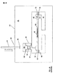
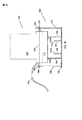
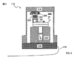
真空筐体110の断面側面図を描いた図5は、装置100のいくつかの追加の構成部品を示し、容量型圧力変換器アセンブリ10がどのように真空筐体110内で固定されているか示している。図5で明らかなとおり、真空筐体110は、バーンアウト、排気および封止される変換器アセンブリ10を固定する銅のセンサ支持体210も含んでいる。変換器アセンブリ10は、ネジ(図示せず)を締め付けることによってセンサ支持体210に固定でき、または変換器アセンブリ10をセンサ支持体210に一時的に固定するのに適する広範囲の他の種類の固定手段によって、センサ支持体210に固定することができる。センサ支持体210に固定される変換器アセンブリ10は、通常、チューブ80の上端部とカバー82の対応する封止面上に置かれる低温封止材料94aを有している。
FIG. 5 depicting a cross-sectional side view of the
装置100は、円筒形の案内アセンブリ300とボール320と銅ウール330とをさらに含んでいる。ボール320は案内アセンブリ300の中空部分内に配置されている。以下により詳細に説明するとおり、案内アセンブリ300は、チューブ80に一時的に結合され、ボール320と共に、封止プロセス中に、カバー82をチューブ80の上端部に向かって案内する。ボール320は、例えば、炭化タングステンまたは窒化ケイ素など、高温高密度の材料で構成されている。案内アセンブリ300と上部筐体114との間に配置される銅ウール330によって、上部筐体114と案内アセンブリ300と変換器アセンブリ10との間に熱伝導経路が形成される。
The
変換器アセンブリ10がセンサ支持体210内に固定された後、センサ支持体210は下部フランジ112に結合され、ボール320と案内アセンブリ300と銅ウール330とが取り付けられ、その後、下部フランジ112が上部筐体114に結合される。組み立て後、下部フランジ112と上部筐体114とは内部真空チャンバ200を形成する。
After the
真空チャンバ200の気密を保証するために、一時的な気密銅シールが、下部フランジ112と上部筐体110との間に設けられる。真空口(図示せず)によって、真空ライン138と真空チャンバ200とが流体連通する。バーンアウト、排気および封止ステップ中に、外部真空ポンプは、真空ライン138と真空口とを介して、超高真空圧まで真空チャンバ200を排気する。
In order to ensure the hermeticity of the
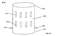
図6Aは、円筒形の案内アセンブリ300をより詳細に示し、一方、図6Bは、案内アセンブリ300の断面図と、ボール320が案内アセンブリ300の中空部分内にどのように配置されているかを示している。円筒形案内アセンブリ300は、閉鎖遠位端312と開放近位端314とを有する中空の円筒形内部空間316を形成している。ボール320は、案内アセンブリ300の空間316内に置かれ、案内アセンブリ300の向きによって、案内アセンブリ300の遠位端312と近位端314の方向またはそこから離れる方向に自由に動くことができる。空間316内のボール320が過度に横方向に動くこと(すなわち、遠位端312と近位端314との間に引かれた線に垂直に動くこと)を防ぐために、ボール320の直径は空間316の直径寸法にほぼ一致している。すなわち、ボール320の直径は空間316の直径よりもわずかに小さい。例示的な一実施形態においては、例えば、ボール320の直径は0.5000±.0001インチであり、空間316の直径は0.505±.002インチである。ボール320と空間361の直径は、バーンアウトおよび排気プロセス中に生じるすべての熱膨張効果を考慮して、適切なサイズに作られている。
6A shows the
案内アセンブリ300の内部空間316はまた、空間316内に一時的に配置されるカバー82およびチューブ80を収容するサイズに構成されている。チューブ80およびカバー82は、通常、同一の半径方向寸法を有している。したがって、空間316の半径方向寸法は、カバー82とチューブ80の半径方向寸法よりもわずかに大きくなるように形成されている。
The
円筒形の案内アセンブリ300は、案内アセンブリ300全体に半径方向に配置された一連の孔310と、案内アセンブリ300の近位端の近くに配置された一連の締め付けネジ318とをさらに含んでいる。締め付けネジ318は、バーンアウト、排気および封止ステップ中に、案内アセンブリ300を(その中に配置されたボール320と共に)チューブ80に一時的に固定するために用いられる。孔310は、案内アセンブリ300の内部空間316と真空チャンバ200との間の流体通路となる。したがって、バーンアウトおよび排気ステップ中、すなわち、カバー82がチューブ80にまだ封止されていないときには、基準チャンバ52と真空チャンバ200との間に、開口48とチューブ80の中空部と孔310とを介した流体通路が存在する。
The
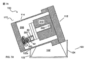
図7Aは、装置100の真空筐体110と案内アセンブリ300とボール320とがバーンアウトおよび排気プロセス中にどのような向きになるかを示す側面図である。図7Bは、図7Aのチューブ80とカバー82と組立案内部300とボール320の向きおよび配置をより正確に描いた拡大側面図を示している。先に記載したとおり、変換器アセンブリ10をセンサ支持体210内に固定する前に、低温封止材料94aがチューブ80の上端部とカバー82の対応する封止領域上に置かれている。変換器アセンブリ10がセンサ支持体210内に固定され、真空チャンバ200が支持アセンブリ120内に封止および固定された後、真空筐体110は、真空筐体110が下部支持体122の遠位端122a上に置かれるようになるまで、反時計方向、すなわち前方に回転する(図7Aに示すとおり)。遠位端122aの位置は、筐体110が回転すると、案内アセンブリ300の内部空間316内に位置するボール320とカバー82とが、チューブ80から離れて案内アセンブリ300の遠位端312の方向に移動するような位置とされる。したがって、真空筐体110を十分に回転させることによって、カバー82とチューブ80との間の間隙(すなわち流体通路)がバーンアウトおよび排気プロセス中に存在することを保証できる。変換器アセンブリ10が所望のバーンアウト温度まで上げられ、吸引されて真空チャンバ200内に超高真空圧が生成されると、変換器アセンブリ10のバーンアウトおよび排気処理が開始される。図7Bの矢印で示されているとおり、変換器アセンブリ10の基準チャンバ52は、汚染物質と気体を、開口48(図示せず)とチューブ80と案内アセンブリ300の孔310とを通して、アセンブリ10を出て真空チャンバ200内に吸引することによって排気する。汚染物質および気体は、その後、外部の真空ポンプによって、真空口と真空ライン138を通して、真空チャンバ300からさらに吸引される。
FIG. 7A is a side view showing how the
ケーブル116を操作して、真空筐体110を反時計回りに回転させることができる。例えば、真空筐体110に荷重を掛けることにより、ケーブル116がたるむと、真空筐体110が反時計回り、すなわち前方に回転するようにできる。
The
バーンアウトおよび排気プロセスが終了すると、基準チャンバ52内の基準圧力は、カバー82をチューブ80に封止することによってチャンバ内に密封される。図8Aは、装置100の真空筐体110と案内アセンブリ300とボール320とがカバー封止プロセス中にどの方向に向いているかを示す側面図である。図8Bは、図8Aのチューブ80とカバー82と案内アセンブリ300とボール320の向きと配置をより正確に描いた拡大側面図を示している。カバー82をチューブ80上で封止するために、装置100の真空筐体110は、下部フランジ112の後方に取り付けられたケーブル116を引っ張ることによって、時計回りの方向、すなわち後方に直立位置まで回転する(図8Aに示されるとおり)。滑車輪または他のタイプの装置もしくは案内部などのケーブル案内(図示せず)を利用して、ケーブル116の操作を容易にできる。真空筐体110が直立位置まで引っ張られると、真空筐体110の下部フランジ112は支持アセンブリ120の上部支持体124の遠位端124a上に置かれる。直立位置は正確に垂直である必要はない。代わりに、真空筐体110が回転すると、わずかに後方に傾くように、上部支持体124の遠位端124aの位置を決めることが好都合である。これにより、ケーブル116の引張りがゆるむ場合に、真空筐体110が前方の下部支持体122の遠位端122aの方向に不注意により回転する可能性が少なくなる。
When the burnout and evacuation process is complete, the reference pressure in the
真空筐体110が直立位置まで回転すると、重力によってボール320が案内アセンブリ300の近位端314の方向に動き、これによってカバー82がチューブ82と係合し、より詳細には、カバー82の底側に配置された低温封止材料94aがチューブ80の上端部上に配置された低温封止材料94aと接合するようになる。したがって、この位置にあるとき、ボール320の重量とカバー82の重量によって、低温封止材料94aの接触面領域でカバー82とチューブ80との間に接触力が与えられる。カバー82をチューブ80上で封止するために、すなわち低温シール94を形成するために、超高真空が真空チャンバ200内に維持されている間に、オーブン内の温度が上昇され、低温封止材料94aの2つの層を融解し、共に融合させる。この温度上昇はまた、チューブ80内に配置されたゲッター素子84を活性化する役割を果たす。低温封止材料94aの層が十分に融解し、共に融合した後、温度は低温封止材料94aの融点以下まで下がり、冷却すると、低温気密シール94がカバー82とチューブ80との間に形成される(図8B)。基準チャンバ52と外部環境、すなわち真空チャンバ200との間に存在する最後の流体通路を閉鎖することによって、シール94が形成されると、基準チャンバ52内に基準圧力が生成される。
As the
シール94が形成されると、オーブンと真空ポンプは電源を遮断され、完成した変換器アセンブリ10が真空筐体110から取り出され、案内アセンブリとボール320が変換器アセンブリ10から取り外される。その後、装置100は、別の変換器アセンブリ10を処理するのに用いることができる。
Once the
装置100は、複数の変換器アセンブリ10を一度に処理するように構成できる。ケーブル116の代わりに、真空筐体110の回転方向を制御するために、有利には、アクチュエータモータ付きのアクチュエータロッド(複数可)を利用する。さらに、本明細書で記載した方法および装置は、絶対圧を測定し、ゲッター素子等を利用する変換器アセンブリ10に関するが、本発明の方法および装置を使用して、さまざまゲージ型圧力変換器アセンブリの基準チャンバ内に基準圧力を生成することもできる。
The
図9は、本開示のバーンアウト、排気および封止プロセスをより詳細に示している。図9では、プロセスフローのx軸は時間を、y軸は摂氏温度を表している。バーンアウトおよび排気ステップが開始される前に、プロセスフローのステップAで、カバー82とボール320と案内アセンブリ3000と圧力変換器アセンブリ10とが真空筐体110の真空チャンバ200内に配置され、図7Aおよび図7Bに示されるとおり、真空筐体110が反時計回り(前方)に回転する。ステップA→Bの間、3時間に亘って、真空チャンバ200内の温度が250℃のバーンアウト温度まで上げられ、圧力が10−8トールの排気圧まで下げられる。バーンアウト温度および排気圧が達成された(ステップB)後、基準チャンバ52は、ステップB→Cで、20時間、バーンアウトおよび排気される。ステップCに到達する直前に、真空筐体100は、図8Aおよび図8Bに示すとおり、直立位置まで時計回り(後方)に回転する。直立位置まで回転すると、ボール320の移動によって、カバー82はチューブ80の方向に移動し、低温封止材料94aの2つの層が互いに接触するようになる。バーンアウトおよび排気ステップが完了する(ステップC)と、真空チャンバ200内の温度は、ステップC→Dで475℃まで上げられ、これによって低温封止材料94aの2つの層が融解する。ステップC→Dは3時間続く。その後、真空チャンバ200は、ステップD→Eで30分間475℃に維持されて、低温封止材料94aの層が共に十分融解するのを保証する。最後に、4時間半に亘って、真空チャンバ200内の温度および圧力が周囲状態に達し、その後、組み立て後の圧力変換器アセンブリ10が、ステップE→Gで、真空筐体110の真空チャンバ200から取り除かれる。
FIG. 9 illustrates the burnout, evacuation and sealing process of the present disclosure in more detail. In FIG. 9, the x-axis of the process flow represents time and the y-axis represents temperature in degrees Celsius. Before the burnout and evacuation steps are initiated, in step A of the process flow, the
低温シール98を融解状態に維持しながら低温シール94を形成しなければならない、従来の方法の中間の温度低下部分を除去することによって(図3のステップE→F)、本開示のバーンアウト、排気および封止プロセスはわずか31時間で完了することができる。したがって、基準チャンバ内に基準圧力を正確に生成することに加えて、本開示はまた、有利には、圧力変換器アセンブリ10のバーンアウト、排気および封止プロセスを実行するのに必要な時間を短縮することもできる。
By removing the intermediate temperature drop portion of the conventional method (step E → F in FIG. 3), which must form the
本発明の教示を組み入れたさまざまな実施形態が本明細書で詳細に示され、説明されてきたが、当業者であれば、これらの教示を組み入れた多くの他の変形実施形態を容易に考案することができる。 While various embodiments incorporating the teachings of the present invention have been shown and described in detail herein, those skilled in the art will readily devise many other variations that incorporate these teachings. can do.
Claims (30)
開口を有する圧力変換器アセンブリを設けることと、
開口カバーを設けることと、
前記開口を取り囲む封止領域と、前記開口カバーの封止領域のうち少なくとも一方の上に封止材料を置くことと、
案内部によって形成される空間内に前記開口カバーを配置することと、
前記開口に隣接する前記圧力変換器アセンブリの一部に前記案内部を結合することと、
前記圧力変換器アセンブリと、前記開口カバーと前記案内部とを筐体の圧力チャンバ内に配置し、前記開口によって、前記圧力変換器アセンブリの前記基準チャンバと前記筐体の前記圧力チャンバとの間に流体通路が設けられることと、
前記圧力チャンバ内に圧力を生成することと、
重力によって前記開口カバーが前記開口の方向に移動するように、前記圧力変換器アセンブリと前記案内部とを回転させることと、
前記封止材料を融解することと、
前記封止材料を冷却させることと、
を含む方法。A method for generating a reference pressure in a reference chamber of a capacitive pressure transducer assembly comprising:
Providing a pressure transducer assembly having an opening;
Providing an opening cover;
Placing a sealing material on at least one of the sealing area surrounding the opening and the sealing area of the opening cover;
Disposing the opening cover in the space formed by the guide portion;
Coupling the guide to a portion of the pressure transducer assembly adjacent to the opening;
The pressure transducer assembly, the opening cover, and the guide are disposed in a pressure chamber of a housing, and the opening causes a gap between the reference chamber of the pressure transducer assembly and the pressure chamber of the housing. A fluid passage is provided in the
Generating pressure in the pressure chamber;
Rotating the pressure transducer assembly and the guide so that the opening cover moves in the direction of the opening by gravity;
Melting the sealing material;
Cooling the sealing material;
Including methods.
前記筐体を前記第1の温度より高い第2の温度にさらし、前記封止材料を融解することと、
をさらに含む、請求項1に記載の方法。Exposing the housing to a first temperature, thereby evaporating at least some contaminants contained within the pressure transducer assembly ;
Exposing the housing to a second temperature higher than the first temperature to melt the sealing material;
The method of claim 1, further comprising:
気密圧力チャンバを形成する圧力筐体であって、上部筐体と下部筐体と圧力口と回転ピンとを備える圧力筐体と、
支持アセンブリであって、前記圧力筐体の前記回転ピンを収容できる孔を有する支持ブラケットを備える支持アセンブリと、
閉鎖遠位端と開放近位端とそれらの間に延びる内部空洞とを有する案内枠と、
を含み、
開口と基準チャンバとを有する圧力変換器アセンブリが、前記圧力筐体の前記圧力チャンバ内に固定され、
開口カバーが前記案内枠の前記近位端の近くの前記内部空洞内に配置され、
前記開口によって、前記圧力変換器アセンブリの前記基準チャンバと前記筐体の前記圧力チャンバとの間に流体通路が設けられ、
封止材料が、前記開口を取り囲む封止領域および前記開口カバーの封止領域のうちの少なくとも一方の上に配置され、
前記案内枠の近位端は、前記開口と隣接する前記圧力変換器アセンブリの一部に結合することができ、
圧力源に接続される圧力ラインが前記圧力口に連結され、
前記圧力源は、前記圧力ラインと前記圧力口を介して前記圧力チャンバ内の圧力状態を生成することができ、
前記回転ピンが前記孔と係合すると、前記圧力筐体は第1の位置から第2の位置まで回転することができ、
前記圧力筐体が前記第1の位置にある場合、前記開口カバーと前記開口との間には間隙が存在し、前記圧力筐体が前記第2の位置まで回転すると、前記開口カバーは前記開口の方向に移動する、装置。An apparatus for easily generating a reference pressure in a reference chamber of a capacitive pressure transducer assembly comprising:
A pressure housing forming an airtight pressure chamber, the pressure housing comprising an upper housing, a lower housing, a pressure port, and a rotation pin;
A support assembly comprising a support bracket having a hole capable of accommodating the rotating pin of the pressure housing;
A guide frame having a closed distal end, an open proximal end and an internal cavity extending therebetween;
Including
A pressure transducer assembly having an opening and a reference chamber is secured within the pressure chamber of the pressure housing;
An opening cover is disposed in the internal cavity near the proximal end of the guide frame;
The opening provides a fluid passageway between the reference chamber of the pressure transducer assembly and the pressure chamber of the housing;
A sealing material is disposed on at least one of a sealing region surrounding the opening and a sealing region of the opening cover;
A proximal end of the guide frame can be coupled to a portion of the pressure transducer assembly adjacent to the opening;
A pressure line connected to a pressure source is connected to the pressure port;
The pressure source can generate a pressure condition in the pressure chamber via the pressure line and the pressure port;
When the rotating pin engages the hole, the pressure housing can rotate from a first position to a second position;
When the pressure housing is in the first position, there is a gap between the opening cover and the opening, and when the pressure housing rotates to the second position, the opening cover A device that moves in the direction of.
前記圧力筐体の一部は、前記圧力筐体が前記第1の位置にあるとき、前記下部支持体上に置かれ、前記圧力筐体の一部は、前記圧力筐体が前記第2の位置にあるとき、前記上部支持体上に置かれる、請求項9に記載の装置。The support assembly further includes an upper support and a lower support,
A portion of the pressure housing is placed on the lower support when the pressure housing is in the first position, and a portion of the pressure housing is The apparatus of claim 9, wherein the apparatus is placed on the upper support when in position.
気密真空チャンバを形成する真空筐体であって、上部筐体と下部筐体と真空口と回転ピンとを備える真空筐体と、
支持アセンブリであって、前記真空筐体の前記回転ピンを収容することができる孔を有する支持ブラケットを備える支持アセンブリと、
閉鎖遠位端と開放近位端とこれらの間に延びる内部空洞とを有する案内部と、
を含み、
開口と基準チャンバとを有する圧力変換器アセンブリが、前記真空筐体の前記真空チャンバ内に固定され、
開口カバーが前記内部空洞内に前記案内部の前記近位端の近くに配置され、
前記開口によって、前記圧力変換器アセンブリの前記基準チャンバと前記筐体の前記真空チャンバとの間に流体通路が設けられ、
封止材料が、前記開口を取り囲む封止領域および前記開口カバーの封止領域のうちの少なくとも一方の上に配置され、
前記案内部の近位端が、前記開口と隣接する前記圧力変換器アセンブリの一部に結合され、
真空源に接続される真空ラインが前記真空口に連結され、前記真空源は、前記真空ラインと前記真空口を介して前記真空チャンバ内の真空圧力状態を生成することができ、
前記回転ピンは前記孔と係合し、前記真空筐体は第1の位置から第2の位置まで回転することができ、
前記真空筐体が前記第1の位置にある場合、前記開口カバーと前記開口との間には間隙が存在し、前記真空筐体が前記第2の位置まで回転すると、前記開口カバーは前記開口の方向に移動する、装置。An apparatus for easily generating a reference pressure in a reference chamber of a capacitive pressure transducer assembly comprising:
A vacuum housing forming an airtight vacuum chamber, the vacuum housing comprising an upper housing, a lower housing, a vacuum port, and a rotating pin;
A support assembly comprising a support bracket having a hole capable of accommodating the rotating pin of the vacuum housing;
A guide having a closed distal end, an open proximal end, and an internal cavity extending therebetween;
Including
A pressure transducer assembly having an opening and a reference chamber is secured within the vacuum chamber of the vacuum housing;
An open cover is disposed in the internal cavity near the proximal end of the guide;
The opening provides a fluid passageway between the reference chamber of the pressure transducer assembly and the vacuum chamber of the housing;
A sealing material is disposed on at least one of a sealing region surrounding the opening and a sealing region of the opening cover;
A proximal end of the guide is coupled to a portion of the pressure transducer assembly adjacent to the opening;
A vacuum line connected to a vacuum source is connected to the vacuum port, and the vacuum source can generate a vacuum pressure state in the vacuum chamber through the vacuum line and the vacuum port,
The rotating pin engages the hole, and the vacuum housing can rotate from a first position to a second position;
When the vacuum casing is in the first position, there is a gap between the opening cover and the opening, and when the vacuum casing rotates to the second position, the opening cover A device that moves in the direction of.
前記真空筐体の一部は、前記真空筐体が前記第1の位置にあるとき、前記下部支持体上に置かれ、前記真空筐体の一部は、前記真空筐体が前記第2の位置にあるとき、前記上部支持体上に置かれている、請求項19に記載の装置。The support assembly further includes an upper support and a lower support,
A portion of the vacuum enclosure is placed on the lower support when the vacuum enclosure is in the first position, and a portion of the vacuum enclosure is disposed on the second enclosure . The apparatus of claim 19, wherein the apparatus is placed on the upper support when in position.
チャンバであって、第1の位置と第2の位置との間を回転可能であり、前記圧力変換器を収容するのに十分な大きさのチャンバと、
前記チャンバに接続されている真空ポンプであって、前記チャンバ内に真空を生成することができる真空ポンプと、
前記チャンバ内に配置されている案内部であって、前記開口近くで前記圧力変換器に取り付けられることができ、前記カバーを収容するのに十分な大きさの内部空間を形成し、前記チャンバが前記第1の位置にあるとき、重力によって前記カバーは前記空間内で前記開口から離れる方向に移動し、前記チャンバが前記第2の位置にあるとき、重力によって前記カバーは前記空間内で前記開口の方向に移動する、案内部と、
前記封止材料を溶融するのに十分高い温度まで、前記チャンバを選択的に加熱する加熱器と、
を含む装置。An apparatus used to construct a pressure transducer , wherein the pressure transducer has a housing and a cover, the housing forms a reference chamber and an opening, and a meltable sealing material is the cover And a device placed on at least one of said housings,
A chamber that is rotatable between a first position and a second position and is large enough to accommodate the pressure transducer ;
A vacuum pump connected to the chamber, the vacuum pump capable of generating a vacuum in the chamber;
A guide disposed within the chamber, which can be attached to the pressure transducer near the opening, forming an internal space large enough to accommodate the cover, the chamber When in the first position, the cover moves in the space away from the opening due to gravity, and when the chamber is in the second position, the cover opens in the space due to gravity. A guide that moves in the direction of
A heater that selectively heats the chamber to a temperature sufficiently high to melt the sealing material;
Including the device.
前記カバーは前記開口と前記重量体との間に配置されている、請求項26に記載の装置。A weight body disposed in the space;
27. The apparatus of claim 26, wherein the cover is disposed between the opening and the weight body.
Applications Claiming Priority (3)
| Application Number | Priority Date | Filing Date | Title |
|---|---|---|---|
| US10/960,153 US7137301B2 (en) | 2004-10-07 | 2004-10-07 | Method and apparatus for forming a reference pressure within a chamber of a capacitance sensor |
| US10/960,153 | 2004-10-07 | ||
| PCT/US2005/035170 WO2006041720A1 (en) | 2004-10-07 | 2005-10-03 | Method and apparatus for forming a reference pressure within a chamber of a capacitance sensor |
Publications (2)
| Publication Number | Publication Date |
|---|---|
| JP2008516231A JP2008516231A (en) | 2008-05-15 |
| JP5154936B2 true JP5154936B2 (en) | 2013-02-27 |
Family
ID=35840422
Family Applications (1)
| Application Number | Title | Priority Date | Filing Date |
|---|---|---|---|
| JP2007535717A Expired - Fee Related JP5154936B2 (en) | 2004-10-07 | 2005-10-03 | Method and apparatus for generating a reference pressure in a chamber of a capacitive sensor |
Country Status (6)
| Country | Link |
|---|---|
| US (2) | US7137301B2 (en) |
| EP (1) | EP1819995B1 (en) |
| JP (1) | JP5154936B2 (en) |
| KR (1) | KR101268769B1 (en) |
| DE (1) | DE602005019317D1 (en) |
| WO (1) | WO2006041720A1 (en) |
Families Citing this family (30)
| Publication number | Priority date | Publication date | Assignee | Title |
|---|---|---|---|---|
| US7141447B2 (en) | 2004-10-07 | 2006-11-28 | Mks Instruments, Inc. | Method of forming a seal between a housing and a diaphragm of a capacitance sensor |
| US7137301B2 (en) | 2004-10-07 | 2006-11-21 | Mks Instruments, Inc. | Method and apparatus for forming a reference pressure within a chamber of a capacitance sensor |
| WO2008122134A1 (en) * | 2007-04-07 | 2008-10-16 | Inficon Gmbh | Method for producing a vacuum measuring cell of the membrane type |
| US7841240B2 (en) * | 2008-04-16 | 2010-11-30 | Kulite Semiconductor Products, Inc. | Header for a differential pressure transducer |
| US7707891B2 (en) * | 2008-06-27 | 2010-05-04 | Inficon Gmbh | Optical interferometric pressure sensor |
| US7913572B2 (en) * | 2009-03-18 | 2011-03-29 | Korea Institute Of Energy Research | Integrated multi-measurement system for measuring physical properties of gas diffusion layer for polymer electrolyte fuel cell with respect to compression |
| FR2947629B1 (en) * | 2009-07-06 | 2012-03-30 | Tronic S Microsystems | PRESSURE MEASURING DEVICE AND METHOD FOR MANUFACTURING THE SAME |
| US8201456B2 (en) * | 2009-11-02 | 2012-06-19 | Vega Grieshaber Kg | Measuring cell and a method of use therefor |
| WO2011097249A1 (en) | 2010-02-02 | 2011-08-11 | Mks Instruments, Inc. | Capacitive pressure sensor |
| DE102010043119A1 (en) * | 2010-10-29 | 2012-05-03 | Endress + Hauser Gmbh + Co. Kg | Method for producing a connection between two ceramic parts, in particular parts of a pressure sensor, and a ceramic product, in particular a ceramic pressure sensor |
| US9016133B2 (en) * | 2011-01-05 | 2015-04-28 | Nxp, B.V. | Pressure sensor with pressure-actuated switch |
| JP2013011556A (en) * | 2011-06-30 | 2013-01-17 | Md Innovations Kk | Diaphragm barometer |
| DE102011078557A1 (en) * | 2011-07-01 | 2013-01-03 | Endress + Hauser Gmbh + Co. Kg | Method for operating an absolute or relative pressure sensor with a capacitive transducer |
| DE102011081887A1 (en) * | 2011-08-31 | 2013-02-28 | Robert Bosch Gmbh | Polymer layer system pressure sensor device and polymer layer system pressure sensor method |
| SG11201400940WA (en) | 2011-09-29 | 2014-04-28 | Mks Instr Inc | Capacitive pressure sensor with improved electrode structure |
| CN104145179B (en) | 2011-10-11 | 2016-11-09 | Mks仪器公司 | Pressure sensor |
| DE102011089608A1 (en) * | 2011-12-22 | 2013-06-27 | Horst Siedle Gmbh & Co. Kg | Housing part for an electrical sensor and method for producing the housing part |
| US9585635B2 (en) * | 2012-12-21 | 2017-03-07 | Volcano Corporation | Apparatus for shaping transducer membranes |
| US9285289B2 (en) | 2013-12-06 | 2016-03-15 | Freescale Semiconductor, Inc. | Pressure sensor with built-in calibration capability |
| DE102013114407A1 (en) * | 2013-12-18 | 2015-06-18 | Endress + Hauser Gmbh + Co. Kg | pressure sensor |
| EP3118601B1 (en) * | 2015-07-15 | 2018-04-18 | Peng Cheng | Torque sensor |
| US10312119B2 (en) * | 2016-02-17 | 2019-06-04 | Lam Research Corporation | Line charge volume with integrated pressure measurement |
| US10515783B2 (en) | 2016-02-23 | 2019-12-24 | Lam Research Corporation | Flow through line charge volume |
| CN107228736A (en) * | 2017-07-20 | 2017-10-03 | 中国电子科技集团公司第四十九研究所 | A kind of miniaturized capacitance formula vacuum pressure sensor encapsulating structure |
| CN107976279A (en) * | 2017-12-15 | 2018-05-01 | 北京创昱科技有限公司 | A kind of vacuum measuring device |
| US11043945B2 (en) * | 2019-03-22 | 2021-06-22 | Yingchao WU | Capacitance-variable pressure sensor |
| US11287342B2 (en) | 2020-03-20 | 2022-03-29 | Mks Instruments, Inc. | Capacitance manometer with improved baffle for improved detection accuracy |
| CN111669964B (en) * | 2020-06-17 | 2021-08-31 | 宿州深湾电子科技有限公司 | Touch-sensitive screen laminating equipment |
| CN114754916B (en) * | 2022-05-11 | 2024-01-09 | 北京七星华创流量计有限公司 | Pressure sensor and manufacturing method |
| KR102666912B1 (en) * | 2023-12-20 | 2024-05-17 | 주식회사 파인솔루션 | CDG device for pressure sensing |
Family Cites Families (232)
| Publication number | Priority date | Publication date | Assignee | Title |
|---|---|---|---|---|
| US2416557A (en) * | 1947-02-25 | Electroacoustic transducer | ||
| US1619444A (en) | 1926-07-08 | 1927-03-01 | Taylor Doc Gilford | Antichattering device |
| FR895938A (en) | 1943-02-24 | 1945-02-07 | Metal diaphragm manolimnigraph | |
| US3000215A (en) | 1951-09-27 | 1961-09-19 | John V Atanasoff | Microbarophone |
| US2800796A (en) * | 1952-08-05 | 1957-07-30 | Trans Souics Inc | Pressure measuring device |
| US2753515A (en) * | 1952-09-03 | 1956-07-03 | Edward J Rickner | Capacitor type differential pressure switch |
| US2755419A (en) * | 1953-06-12 | 1956-07-17 | Hans E Hollmann | Electromechanical nonlinear capacitor |
| US2751530A (en) * | 1954-01-04 | 1956-06-19 | Honeywell Regulator Co | Differential pressure sensing unit |
| US2907320A (en) | 1954-01-11 | 1959-10-06 | Texas Instruments Inc | Pressure capacitance transducer |
| US2999386A (en) | 1956-11-02 | 1961-09-12 | Trans Sonics Inc | High precision diaphragm type instruments |
| US3113459A (en) | 1959-04-29 | 1963-12-10 | North American Aviation Inc | Pressure measuring device |
| US3318153A (en) * | 1962-12-04 | 1967-05-09 | Rosemount Eng Co Ltd | Diode loop capacitor comparative circuit including a pair of transformer windings coupled in phase |
| US3153847A (en) | 1963-08-02 | 1964-10-27 | Jr John E Lindberg | Method of making heat sensors |
| DE1282302B (en) | 1964-03-11 | 1968-11-07 | Micromatic Hone Corp | Capacitive transmitter |
| US3243998A (en) * | 1964-11-17 | 1966-04-05 | Robert E Vosteen | Capacitor measuring and detecting device |
| US3460310A (en) * | 1964-12-09 | 1969-08-12 | United Glass Ltd | Container closures |
| US3371537A (en) * | 1965-09-16 | 1968-03-05 | William J. Kiene | Pressure indicator |
| US3354721A (en) | 1965-10-23 | 1967-11-28 | Augustus H Fiske | Pressure gaging systems of apparatus |
| US3620083A (en) | 1969-12-04 | 1971-11-16 | Nasa | Wide range dynamic pressure sensor |
| US3619742A (en) | 1970-05-21 | 1971-11-09 | Rosemount Eng Co Ltd | Shielded capacitance pressure sensor |
| US3675072A (en) * | 1971-01-28 | 1972-07-04 | Atomic Energy Commission | Fast-closing valve system for cyclotrons |
| US3858097A (en) | 1973-12-26 | 1974-12-31 | Bendix Corp | Pressure-sensing capacitor |
| GB1450709A (en) * | 1973-12-31 | 1976-09-29 | Birchall D J | Pressure transducers |
| SE412956B (en) | 1974-04-04 | 1980-03-24 | Rosemount Inc | CAPACITIVE SENSING DEVICE |
| DE2443559C2 (en) * | 1974-09-11 | 1984-01-12 | Interatom Internationale Atomreaktorbau Gmbh, 5060 Bergisch Gladbach | Device for taking samples from a circuit carrying liquid metal |
| US4084439A (en) * | 1975-10-01 | 1978-04-18 | King Radio Corporation | Pressure transducer with capacitor pick-up means |
| US4008619A (en) * | 1975-11-17 | 1977-02-22 | Mks Instruments, Inc. | Vacuum monitoring |
| US4011901A (en) * | 1976-03-10 | 1977-03-15 | Massachusetts Institute Of Technology | Method determining the suitability of metal compositions for casting |
| US4426673A (en) * | 1976-03-12 | 1984-01-17 | Kavlico Corporation | Capacitive pressure transducer and method of making same |
| US4084438A (en) * | 1976-03-29 | 1978-04-18 | Setra Systems, Inc. | Capacitive pressure sensing device |
| US4020674A (en) * | 1976-05-19 | 1977-05-03 | Harry Robert Fechter | Pipeline leak detector with baffles |
| US4176557A (en) | 1976-06-07 | 1979-12-04 | Bunker Ramo Corporation | Pressure sensor |
| US4091683A (en) | 1976-09-27 | 1978-05-30 | Panex, Inc. | Single channel electrical comparative measuring system |
| US4120206A (en) | 1977-01-17 | 1978-10-17 | Rosemount Inc. | Differential pressure sensor capsule with low acceleration sensitivity |
| US4334725A (en) * | 1977-01-28 | 1982-06-15 | Stanley Electric Co., Ltd. | Method for making a fluorescent lamp |
| US4168518A (en) | 1977-05-10 | 1979-09-18 | Lee Shih Y | Capacitor transducer |
| JPS5640918Y2 (en) | 1977-07-29 | 1981-09-25 | ||
| US4141252A (en) * | 1977-11-04 | 1979-02-27 | Lodge Arthur S | Flush pressure transducers for measuring pressures in a flowing fluid |
| US4168517A (en) | 1977-11-10 | 1979-09-18 | Lee Shih Y | Capacitive pressure transducer |
| US4136603A (en) * | 1977-11-14 | 1979-01-30 | The Foxboro Company | Diaphragm assembly |
| US4178621A (en) | 1978-01-23 | 1979-12-11 | Motorola, Inc. | Electromechanical pressure transducer |
| US4229776A (en) | 1978-11-21 | 1980-10-21 | Vaisala Oy | Capacitive capsule for aneroid pressure gauge |
| DE2902623A1 (en) | 1979-01-24 | 1980-07-31 | Messer Griesheim Gmbh | METHOD AND GRID ARRANGEMENT FOR MAINTAINING A VACUUM |
| US4227419A (en) | 1979-09-04 | 1980-10-14 | Kavlico Corporation | Capacitive pressure transducer |
| US4322775A (en) * | 1979-10-29 | 1982-03-30 | Delatorre Leroy C | Capacitive pressure sensor |
| US4302063A (en) | 1980-02-28 | 1981-11-24 | Rca Corporation | Method for vaporizing getter material in a vacuum electron tube |
| DE3031983C2 (en) * | 1980-08-25 | 1987-02-26 | Erich Dr.-Ing. 5300 Bonn Steingroever | Device for magnetizing permanent magnets |
| US4343188A (en) | 1980-08-27 | 1982-08-10 | Baker William E | Fluid pressure indicating apparatus |
| US4357834A (en) | 1980-09-03 | 1982-11-09 | Hokushin Electric Works, Ltd. | Displacement converter |
| US4358814A (en) | 1980-10-27 | 1982-11-09 | Setra Systems, Inc. | Capacitive pressure sensor |
| US4434203A (en) * | 1980-10-27 | 1984-02-28 | Setra Systems, Inc. | Diaphragm |
| US4422335A (en) | 1981-03-25 | 1983-12-27 | The Bendix Corporation | Pressure transducer |
| US4458537A (en) * | 1981-05-11 | 1984-07-10 | Combustion Engineering, Inc. | High accuracy differential pressure capacitive transducer |
| US4464725A (en) * | 1981-05-19 | 1984-08-07 | Setra Systems, Inc. | Temperature compensated measuring system |
| US4389895A (en) * | 1981-07-27 | 1983-06-28 | Rosemount Inc. | Capacitance pressure sensor |
| JPS5855732A (en) * | 1981-09-30 | 1983-04-02 | Hitachi Ltd | Electrostatic capacity type pressure sensor |
| JPS58160832A (en) * | 1982-03-18 | 1983-09-24 | Matsushita Electric Ind Co Ltd | Capacitive pressure sensor |
| US4413524A (en) | 1982-03-26 | 1983-11-08 | Dresser Industries, Inc. | Pulsation throttling device for a pressure gauge |
| US4422125A (en) | 1982-05-21 | 1983-12-20 | The Bendix Corporation | Pressure transducer with an invariable reference capacitor |
| US4425799A (en) * | 1982-06-03 | 1984-01-17 | Kavlico Corporation | Liquid capacitance pressure transducer technique |
| US4424713A (en) * | 1982-06-11 | 1984-01-10 | General Signal Corporation | Silicon diaphragm capacitive pressure transducer |
| US4433580A (en) * | 1982-07-22 | 1984-02-28 | Tward 2001 Limited | Pressure transducer |
| US4598381A (en) * | 1983-03-24 | 1986-07-01 | Rosemount Inc. | Pressure compensated differential pressure sensor and method |
| US4499773A (en) * | 1983-04-28 | 1985-02-19 | Dresser Industries, Inc. | Variable capacitance pressure transducer |
| US4523474A (en) * | 1983-08-12 | 1985-06-18 | Borg-Warner Corporation | Capacitive pressure sensor |
| US4567773A (en) * | 1984-01-05 | 1986-02-04 | Energy Utilization Laboratories, Inc. | Pressure transducer system |
| JPS60120833U (en) | 1984-01-24 | 1985-08-15 | 大日本印刷株式会社 | makeup sheet |
| FI74350C (en) | 1984-02-21 | 1988-01-11 | Vaisala Oy | Capacitive absolute pressure sensor. |
| US4572204A (en) * | 1984-03-21 | 1986-02-25 | Hewlett-Packard Company | Pressure dome with compliant chamber |
| US4542436A (en) | 1984-04-10 | 1985-09-17 | Johnson Service Company | Linearized capacitive pressure transducer |
| JPS6119028A (en) | 1984-07-04 | 1986-01-27 | Sony Corp | Mounting of stud pins on cathode-ray tube panel |
| US4562742A (en) * | 1984-08-07 | 1986-01-07 | Bell Microcomponents, Inc. | Capacitive pressure transducer |
| US4603371A (en) * | 1984-10-12 | 1986-07-29 | Rosemount Inc. | Capacitive sensing cell made of brittle material |
| NL8500139A (en) * | 1985-01-21 | 1986-08-18 | Advanced Micro Electronic | CAPACITIVE WEIGHING. |
| US4881939A (en) | 1985-02-19 | 1989-11-21 | The Johns Hopkins University | Implantable helical cuff |
| US4587851A (en) * | 1985-02-26 | 1986-05-13 | Edward Mortberg | High vacuum capacitance manometer having Px side open housing |
| JPH064371B2 (en) * | 1985-04-22 | 1994-01-19 | 日本電気ホームエレクトロニクス株式会社 | Vehicle height control device |
| US4670733A (en) * | 1985-07-01 | 1987-06-02 | Bell Microsensors, Inc. | Differential pressure transducer |
| US4735098A (en) * | 1985-11-19 | 1988-04-05 | Kavlico Corporation | Dual diaphragm differential pressure transducer |
| GB2184841B (en) * | 1985-11-22 | 1989-12-28 | Mitutoyo Mfg Co Ltd | Electronic display measuring device |
| US4617607A (en) | 1985-12-10 | 1986-10-14 | Kavlico Corporation | High pressure capacitive transducer |
| US4691574A (en) | 1986-02-25 | 1987-09-08 | Delatorre Leroy C | Capacitance transducer |
| US5279163A (en) * | 1986-02-28 | 1994-01-18 | Antonio Nicholas F D | Sensor and transducer apparatus |
| GB2188155B (en) | 1986-03-21 | 1990-01-10 | Furness Controls Ltd | Pressure transducer |
| JPS62172117U (en) | 1986-04-22 | 1987-10-31 | ||
| US4815324A (en) * | 1986-04-24 | 1989-03-28 | Mitsubishi Denki Kabushiki Kaisha | Intake air meter for an internal combustion engine |
| US4774626A (en) | 1986-05-05 | 1988-09-27 | Texas Instruments Incorporated | Pressure sensor with improved capacitive pressure transducer |
| US4738276A (en) * | 1986-06-06 | 1988-04-19 | Adams Donald L | Modular differential pressure transmitter/manifold for a fluid conveying pipeline |
| US4703658A (en) | 1986-06-18 | 1987-11-03 | Motorola, Inc. | Pressure sensor assembly |
| US4730496A (en) | 1986-06-23 | 1988-03-15 | Rosemount Inc. | Capacitance pressure sensor |
| SU1362971A1 (en) | 1986-07-01 | 1987-12-30 | Предприятие П/Я А-1891 | Method of vacuum treatment of absolute pressure transmitters and device for effecting same |
| US4943032A (en) | 1986-09-24 | 1990-07-24 | Stanford University | Integrated, microminiature electric to fluidic valve and pressure/flow regulator |
| US4714464A (en) | 1986-10-27 | 1987-12-22 | Entravision, Inc. | Mechanism for coupling the aspirant line of an irrigation/aspiration machine to the pressure monitoring section |
| US4765188A (en) * | 1986-11-24 | 1988-08-23 | Bourns Instruments, Inc. | Pressure transducer with integral digital temperature compensation |
| US4735090A (en) * | 1986-11-28 | 1988-04-05 | Honeywell Inc. | Flange mounted pressure transmitter |
| JPS63149531A (en) | 1986-12-12 | 1988-06-22 | Fuji Electric Co Ltd | capacitive pressure sensor |
| IT1201540B (en) | 1986-12-22 | 1989-02-02 | Getters Spa | NON-EVAPORABLE GETTER DEVICE INCLUDING A CERAMIC SUPPORT AND METHOD FOR ITS MANUFACTURE |
| SE459887B (en) * | 1987-02-12 | 1989-08-14 | Hydrolab Ab | PRESSURE TRANSMITTER |
| FI872049A7 (en) | 1987-05-08 | 1988-11-09 | Vaisala Oy | Capacitor structure used in a pressure sensor. |
| US4785669A (en) | 1987-05-18 | 1988-11-22 | Mks Instruments, Inc. | Absolute capacitance manometers |
| US4851015A (en) * | 1987-08-21 | 1989-07-25 | Donaldson Company, Inc. | Muffler apparatus with filter trap and method of use |
| US4875368A (en) | 1987-09-08 | 1989-10-24 | Panex Corporation | Pressure sensor system |
| JPH0812123B2 (en) * | 1987-11-27 | 1996-02-07 | 日本碍子株式会社 | Pressure sensor |
| US4850227A (en) * | 1987-12-22 | 1989-07-25 | Delco Electronics Corporation | Pressure sensor and method of fabrication thereof |
| JPH01182729A (en) * | 1988-01-16 | 1989-07-20 | Ngk Insulators Ltd | Pressure sensor |
| US4807477A (en) * | 1988-02-01 | 1989-02-28 | Motorola, Inc. | Capacitive temperature compensation for a pressure sensor |
| JPH01204022A (en) | 1988-02-10 | 1989-08-16 | Nec Corp | Manufacture of liquid crystal element |
| US5497620A (en) * | 1988-04-08 | 1996-03-12 | Stobbe; Per | Method of filtering particles from a flue gas, a flue gas filter means and a vehicle |
| US4864463A (en) | 1988-04-19 | 1989-09-05 | Allied-Signal Inc. | Capacitive pressure sensor |
| US4823603A (en) * | 1988-05-03 | 1989-04-25 | Vacuum General, Inc. | Capacitance manometer having stress relief for fixed electrode |
| JPH01281691A (en) | 1988-05-09 | 1989-11-13 | Fuji Iryo Sokki Kk | Extreme infrared radiation generating apparatus |
| SE461300B (en) | 1988-05-17 | 1990-01-29 | Hydrolab Ab | TRYCKMAETARE |
| DE3901492A1 (en) * | 1988-07-22 | 1990-01-25 | Endress Hauser Gmbh Co | PRESSURE SENSOR AND METHOD FOR THE PRODUCTION THEREOF |
| US4977480A (en) | 1988-09-14 | 1990-12-11 | Fuji Koki Mfg. Co., Ltd. | Variable-capacitance type sensor and variable-capacitance type sensor system using the same |
| US4944187A (en) * | 1988-12-23 | 1990-07-31 | Rosemount Inc. | Multimodulus pressure sensor |
| US5048165A (en) | 1989-01-30 | 1991-09-17 | Dresser Industries, Inc. | Method for controlling the sensitivity and linearity of capacitive transducer systems |
| DE3910646A1 (en) * | 1989-04-01 | 1990-10-04 | Endress Hauser Gmbh Co | CAPACITIVE PRESSURE SENSOR AND METHOD FOR THE PRODUCTION THEREOF |
| US5134887A (en) * | 1989-09-22 | 1992-08-04 | Bell Robert L | Pressure sensors |
| US5165281A (en) | 1989-09-22 | 1992-11-24 | Bell Robert L | High pressure capacitive transducer |
| FR2656698B1 (en) * | 1989-12-29 | 1992-05-07 | Vectavib | DEVICE FOR MEASURING VARIATIONS IN THE CAPACITY OF A CAPACITOR FORMING, IN PARTICULAR, A SENSOR. |
| US5050034A (en) | 1990-01-22 | 1991-09-17 | Endress U. Hauser Gmbh U. Co. | Pressure sensor and method of manufacturing same |
| US5020377A (en) * | 1990-01-23 | 1991-06-04 | Kavlico Corporation | Low pressure transducer using metal foil diaphragm |
| DE4011901A1 (en) | 1990-04-12 | 1991-10-17 | Vdo Schindling | Capacitive pressure sensor with simultaneous temp. measurement - contains plates carrying electrodes, one carrying temp. dependent resistance path |
| JP2724419B2 (en) | 1990-08-28 | 1998-03-09 | 日本特殊陶業株式会社 | Pressure sensor |
| DE4031791A1 (en) | 1990-10-08 | 1992-04-09 | Leybold Ag | CAPACITY GAUGE SENSOR |
| DE4129414A1 (en) | 1990-11-13 | 1993-03-11 | Endress Hauser Gmbh Co | Ternary activated solder |
| US5228334A (en) | 1990-12-28 | 1993-07-20 | Hi-Stat Manufacturing Co., Inc. | Pressure transducer |
| DE4111118A1 (en) | 1991-04-03 | 1992-10-08 | Univ Chemnitz Tech | MICROMECHANICAL CAPACITIVE PRESSURE TRANSDUCER |
| US5188780A (en) | 1991-04-18 | 1993-02-23 | Regents Of The University Of California | Method for preparation of dense ceramic products |
| EP0516579B1 (en) * | 1991-05-26 | 1994-06-22 | Endress + Hauser Gmbh + Co. | Interface connection through an insulating part |
| US5186055A (en) * | 1991-06-03 | 1993-02-16 | Eaton Corporation | Hermetic mounting system for a pressure transducer |
| US5291534A (en) * | 1991-06-22 | 1994-03-01 | Toyoda Koki Kabushiki Kaisha | Capacitive sensing device |
| US5150275A (en) | 1991-07-01 | 1992-09-22 | Setra Systems, Inc. | Capacitive pressure sensor |
| US5155653A (en) | 1991-08-14 | 1992-10-13 | Maclean-Fogg Company | Capacitive pressure sensor |
| DE4136995C2 (en) | 1991-11-11 | 1996-08-08 | Sensycon Ind Sensorsyst | Capacitive pressure sensor |
| EP0544934B1 (en) * | 1991-11-30 | 1996-10-02 | Endress U. Hauser Gmbh U. Co. | Method of stabilizing the surface properties of objects to be thermally treated in a vacuum |
| US5369228A (en) | 1991-11-30 | 1994-11-29 | Signagraphics Corporation | Data input device with a pressure-sensitive input surface |
| US5271277A (en) | 1991-12-23 | 1993-12-21 | The Boc Group, Inc. | Capacitance pressure transducer |
| JP2896725B2 (en) | 1991-12-26 | 1999-05-31 | 株式会社山武 | Capacitive pressure sensor |
| US5348568A (en) | 1992-02-05 | 1994-09-20 | Asahi Glass Company Ltd. | Filtering method of flue gas of a boiler and a filter apparatus for hot gas |
| US5189591A (en) * | 1992-06-12 | 1993-02-23 | Allied-Signal Inc. | Aluminosilicate glass pressure transducer |
| US5499533A (en) * | 1992-08-26 | 1996-03-19 | Miller; Mark | Downhole pressure gauge converter |
| US5275055A (en) * | 1992-08-31 | 1994-01-04 | Honeywell Inc. | Resonant gauge with microbeam driven in constant electric field |
| DE69316536T2 (en) | 1992-11-06 | 1998-06-04 | Texas Instruments Inc | Method of manufacturing a capacitive pressure transducer |
| US5351548A (en) | 1992-12-02 | 1994-10-04 | Walbro Corporation | Capacitive pressure sensor |
| US5315877A (en) * | 1993-02-19 | 1994-05-31 | Kavlico Corporation | Low cost versatile pressure transducer |
| US5561247A (en) | 1993-03-30 | 1996-10-01 | Honda Motor Co., Ltd. | Pressure sensor |
| US5571970A (en) | 1993-03-30 | 1996-11-05 | Honda Motor Co., Ltd. | Pressure sensor |
| US5343755A (en) | 1993-05-05 | 1994-09-06 | Rosemount Inc. | Strain gage sensor with integral temperature signal |
| US5333637A (en) * | 1993-06-11 | 1994-08-02 | Rosemount Inc. | Pneumatic instrument particle trap |
| KR960002929B1 (en) * | 1993-07-24 | 1996-02-28 | 엘지전자주식회사 | Crt getter device |
| FI93579C (en) | 1993-08-20 | 1995-04-25 | Vaisala Oy | Capacitive encoder feedback with electrostatic force and method for controlling the shape of its active element |
| US5442962A (en) | 1993-08-20 | 1995-08-22 | Setra Systems, Inc. | Capacitive pressure sensor having a pedestal supported electrode |
| US5349865A (en) | 1993-08-30 | 1994-09-27 | Kavlico Corporation | Wide-pressure-range, adaptable, simplified pressure transducer |
| US5541561A (en) * | 1993-12-03 | 1996-07-30 | Eaton Corporation | Integral electrical circuit controller |
| DE69412769T2 (en) * | 1993-12-07 | 1999-01-14 | Matsushita Electric Industrial Co., Ltd., Kadoma, Osaka | Capacitive sensor and manufacturing method |
| JP2975832B2 (en) | 1993-12-27 | 1999-11-10 | 住友重機械工業株式会社 | Tank container |
| US5542300A (en) * | 1994-01-24 | 1996-08-06 | Setra Systems, Inc. | Low cost, center-mounted capacitive pressure sensor |
| US5436795A (en) | 1994-03-28 | 1995-07-25 | Texas Instruments Incorporated | Pressure transducer apparatus and method for making same |
| SE506558C2 (en) | 1994-04-14 | 1998-01-12 | Cecap Ab | Sensor element for pressure transducer |
| SE516716C2 (en) | 1994-04-14 | 2002-02-19 | Mks Instr | Pressure transducer for measuring the pressure of a fluid |
| US5536114A (en) * | 1994-05-20 | 1996-07-16 | Stir-Melter, Inc. | Apparatus for vitrifcation of hazardous waste |
| IT1271207B (en) | 1994-07-07 | 1997-05-27 | Getters Spa | DEVICE FOR THE MAINTENANCE OF THE VACUUM IN THERMALLY INSULATING SPACES AND PROCEDURE FOR ITS PRODUCTION |
| IT1270598B (en) * | 1994-07-07 | 1997-05-07 | Getters Spa | COMBINATION OF MATERIALS FOR MERCURY DISPENSING DEVICES PREPARATION METHOD AND DEVICES SO OBTAINED |
| US5485345A (en) * | 1994-11-14 | 1996-01-16 | Texas Instruments Incorporated | Pressure transducer apparatus |
| US5499158A (en) | 1994-11-14 | 1996-03-12 | Texas Instruments Incorporated | Pressure transducer apparatus with monolithic body of ceramic material |
| JPH08159377A (en) * | 1994-12-02 | 1996-06-21 | Matsushita Refrig Co Ltd | Vacuum heat insulator |
| US5604315A (en) * | 1995-01-12 | 1997-02-18 | Setra Systems, Inc. | Apparatus using a feedback network to measure fluid pressures |
| US5808206A (en) | 1996-01-16 | 1998-09-15 | Mks Instruments, Inc. | Heated pressure transducer assembly |
| US5625152A (en) * | 1996-01-16 | 1997-04-29 | Mks Instruments, Inc. | Heated pressure transducer assembly |
| US5800235A (en) | 1996-02-27 | 1998-09-01 | Illumination Technology, Inc. | Process for manufacturing incandescent lamps having gettering agents |
| EP0797084B1 (en) | 1996-03-23 | 2001-01-17 | Endress + Hauser GmbH + Co. | Method of manufacturing capacitive ceramic absolute pressure sensors classified in zero-point long-term stability groups |
| JP3107516B2 (en) * | 1996-05-01 | 2000-11-13 | 株式会社日立製作所 | Composite sensor |
| US5888845A (en) | 1996-05-02 | 1999-03-30 | National Semiconductor Corporation | Method of making high sensitivity micro-machined pressure sensors and acoustic transducers |
| US5672808A (en) * | 1996-06-11 | 1997-09-30 | Moore Products Co. | Transducer having redundant pressure sensors |
| JP3147778B2 (en) * | 1996-07-01 | 2001-03-19 | 富士電機株式会社 | Capacitive differential pressure detector |
| DE29615534U1 (en) | 1996-09-06 | 1996-10-24 | Dbt Gmbh | Pressure transducer for measuring hydraulic pressures, especially for mining applications |
| US5811685A (en) | 1996-12-11 | 1998-09-22 | Mks Instruments, Inc. | Fluid pressure sensor with contaminant exclusion system |
| SE9700613D0 (en) | 1997-02-20 | 1997-02-20 | Cecap Ab | Sensor element with temperature measurement |
| SE9700612D0 (en) * | 1997-02-20 | 1997-02-20 | Cecap Ab | Sensor element with integrated reference pressure |
| US5942692A (en) | 1997-04-10 | 1999-08-24 | Mks Instruments, Inc. | Capacitive pressure sensing method and apparatus avoiding interelectrode capacitance by driving with in-phase excitation signals |
| US5911162A (en) * | 1997-06-20 | 1999-06-08 | Mks Instruments, Inc. | Capacitive pressure transducer with improved electrode support |
| US5965821A (en) | 1997-07-03 | 1999-10-12 | Mks Instruments, Inc. | Pressure sensor |
| DK0915326T3 (en) | 1997-10-10 | 2002-03-25 | Wika Alexander Wiegand Gmbh | Process for producing a pressure target transducer and pressure target transducer |
| US6019002A (en) | 1997-12-02 | 2000-02-01 | Setra Systems, Inc. | Pressure transducer having a tensioned diaphragm |
| US5939639A (en) | 1997-12-04 | 1999-08-17 | Setra Systems, Inc. | Pressure transducer housing with barometric pressure isolation |
| SE9704840D0 (en) | 1997-12-22 | 1997-12-22 | Cecap Ab | Pressure sensor for detecting small pressure differences and low pressures |
| US20040099061A1 (en) | 1997-12-22 | 2004-05-27 | Mks Instruments | Pressure sensor for detecting small pressure differences and low pressures |
| WO1999034184A1 (en) | 1997-12-23 | 1999-07-08 | Unaxis Trading Ag | Capacitive vacuum measuring cell |
| JP4334139B2 (en) * | 1997-12-23 | 2009-09-30 | インフィコン ゲゼルシャフト ミット ベシュレンクテル ハフツング | Diaphragm for capacitive vacuum measuring cell |
| US6568274B1 (en) * | 1998-02-04 | 2003-05-27 | Mks Instruments, Inc. | Capacitive based pressure sensor design |
| US6029525A (en) | 1998-02-04 | 2000-02-29 | Mks Instruments, Inc. | Capacitive based pressure sensor design |
| US5948169A (en) | 1998-03-11 | 1999-09-07 | Vanguard International Semiconductor Corporation | Apparatus for preventing particle deposition in a capacitance diaphragm gauge |
| WO1999047357A1 (en) | 1998-03-18 | 1999-09-23 | Seiko Epson Corporation | Electrostatic actuator, its manufacturing method, and liquid injection device using them |
| DE19811970C2 (en) | 1998-03-19 | 2000-05-18 | Klaus Kobold | Measuring display device |
| US6209398B1 (en) * | 1998-09-18 | 2001-04-03 | Texas Instruments Incorporated | Fluid pressure transducer apparatus and method for assembling |
| US6340929B1 (en) * | 1998-11-19 | 2002-01-22 | Pacific Industrial Co., Ltd | Transmitter and external controller of tire inflation pressure monitor |
| US6205861B1 (en) | 1999-01-22 | 2001-03-27 | Setra Systems, Inc. | Transducer having temperature compensation |
| US6423949B1 (en) * | 1999-05-19 | 2002-07-23 | Applied Materials, Inc. | Multi-zone resistive heater |
| US6578427B1 (en) * | 1999-06-15 | 2003-06-17 | Envec Mess- Und Regeltechnik Gmbh + Co. | Capacitive ceramic relative-pressure sensor |
| US6105436A (en) | 1999-07-23 | 2000-08-22 | Mks Instruments, Inc. | Capacitive pressure transducer with improved electrode support |
| US6443015B1 (en) | 1999-09-10 | 2002-09-03 | Mks Instruments, Inc. | Baffle for a capacitive pressure sensor |
| US6424880B1 (en) | 1999-09-10 | 2002-07-23 | Applied Materials, Inc. | Multi-computer chamber control system, method and medium |
| US6148674A (en) | 1999-09-15 | 2000-11-21 | Park; Kyong M. | Shielded capacitive pressure sensor |
| JP3213296B2 (en) | 1999-11-01 | 2001-10-02 | 日本コーリン株式会社 | Pulse wave velocity information measurement device |
| AU2629901A (en) * | 2000-01-06 | 2001-07-16 | Rosemount Inc. | Grain growth of electrical interconnection for microelectromechanical systems (mems) |
| EP1309840B1 (en) | 2000-08-11 | 2010-06-09 | MKS Instruments, Inc. | Capacitive based pressure sensor design |
| US6698294B2 (en) | 2000-09-07 | 2004-03-02 | Vega Grieshaber Kg | Pressure cell with temperature sensors and pressure measuring method |
| US6451159B1 (en) | 2000-09-20 | 2002-09-17 | Lam Research Corporation | Grounded centering ring for inhibiting polymer build-up on the diaphragm of a manometer |
| US6772640B1 (en) | 2000-10-10 | 2004-08-10 | Mks Instruments, Inc. | Multi-temperature heater for use with pressure transducers |
| US6612176B2 (en) | 2000-12-28 | 2003-09-02 | Mks Instruments, Inc. | Pressure transducer assembly with thermal shield |
| GB0103886D0 (en) | 2001-02-16 | 2001-04-04 | Baumbach Per L | Temperature measuring device |
| US6581471B1 (en) * | 2001-11-30 | 2003-06-24 | Mks Instruments, Inc. | Output device for pressure transducer |
| DE10163567A1 (en) | 2001-12-21 | 2003-07-17 | Endress & Hauser Gmbh & Co Kg | Pressure sensor with a hydrophobic coating |
| US20030121332A1 (en) | 2001-12-21 | 2003-07-03 | Mathew Santhi E. | Pressure transducer with dual slope output |
| US6901808B1 (en) | 2002-02-12 | 2005-06-07 | Lam Research Corporation | Capacitive manometer having reduced process drift |
| US7252011B2 (en) | 2002-03-11 | 2007-08-07 | Mks Instruments, Inc. | Surface area deposition trap |
| US6892745B2 (en) | 2002-04-10 | 2005-05-17 | Honeywell International Inc. | Flow control valve with integral sensor and controller and related method |
| US6588280B1 (en) | 2002-04-22 | 2003-07-08 | Mks Instruments, Inc. | Pressure transducer with compensation for thermal transients |
| JP2004012141A (en) | 2002-06-03 | 2004-01-15 | Omron Corp | Capacitive pressure sensor and method of manufacturing the same |
| US6846380B2 (en) * | 2002-06-13 | 2005-01-25 | The Boc Group, Inc. | Substrate processing apparatus and related systems and methods |
| US20040002655A1 (en) | 2002-06-27 | 2004-01-01 | Acuson, A Siemens Company | System and method for improved transducer thermal design using thermo-electric cooling |
| US7314447B2 (en) | 2002-06-27 | 2008-01-01 | Siemens Medical Solutions Usa, Inc. | System and method for actively cooling transducer assembly electronics |
| US6845664B1 (en) | 2002-10-03 | 2005-01-25 | The United States Of America As Represented By The Administrator Of National Aeronautics And Space Administration | MEMS direct chip attach packaging methodologies and apparatuses for harsh environments |
| US6736370B1 (en) | 2002-12-20 | 2004-05-18 | Applied Materials, Inc. | Diaphragm valve with dynamic metal seat and coned disk springs |
| US6964501B2 (en) | 2002-12-24 | 2005-11-15 | Altman Stage Lighting Co., Ltd. | Peltier-cooled LED lighting assembly |
| JP4159895B2 (en) * | 2003-02-17 | 2008-10-01 | キヤノンアネルバ株式会社 | Capacitance type pressure sensor and manufacturing method thereof |
| US6993973B2 (en) | 2003-05-16 | 2006-02-07 | Mks Instruments, Inc. | Contaminant deposition control baffle for a capacitive pressure transducer |
| CN100424905C (en) | 2003-10-07 | 2008-10-08 | 松下电器产业株式会社 | Thermoelectric conversion element, method for manufacturing same, cooling device using thermoelectric conversion element, and method for controlling cooling device |
| US7137301B2 (en) | 2004-10-07 | 2006-11-21 | Mks Instruments, Inc. | Method and apparatus for forming a reference pressure within a chamber of a capacitance sensor |
| US7141447B2 (en) | 2004-10-07 | 2006-11-28 | Mks Instruments, Inc. | Method of forming a seal between a housing and a diaphragm of a capacitance sensor |
| US7204150B2 (en) | 2005-01-14 | 2007-04-17 | Mks Instruments, Inc. | Turbo sump for use with capacitive pressure sensor |
-
2004
- 2004-10-07 US US10/960,153 patent/US7137301B2/en not_active Expired - Lifetime
-
2005
- 2005-10-03 WO PCT/US2005/035170 patent/WO2006041720A1/en not_active Ceased
- 2005-10-03 JP JP2007535717A patent/JP5154936B2/en not_active Expired - Fee Related
- 2005-10-03 DE DE602005019317T patent/DE602005019317D1/en not_active Expired - Lifetime
- 2005-10-03 KR KR1020077010355A patent/KR101268769B1/en not_active Expired - Lifetime
- 2005-10-03 EP EP05803857A patent/EP1819995B1/en not_active Ceased
-
2006
- 2006-10-03 US US11/542,316 patent/US7624643B2/en active Active
Also Published As
| Publication number | Publication date |
|---|---|
| EP1819995B1 (en) | 2010-02-10 |
| US7137301B2 (en) | 2006-11-21 |
| US7624643B2 (en) | 2009-12-01 |
| US20060075823A1 (en) | 2006-04-13 |
| US20070023140A1 (en) | 2007-02-01 |
| EP1819995A1 (en) | 2007-08-22 |
| KR20070063030A (en) | 2007-06-18 |
| JP2008516231A (en) | 2008-05-15 |
| DE602005019317D1 (en) | 2010-03-25 |
| WO2006041720A1 (en) | 2006-04-20 |
| KR101268769B1 (en) | 2013-05-29 |
Similar Documents
| Publication | Publication Date | Title |
|---|---|---|
| JP5154936B2 (en) | Method and apparatus for generating a reference pressure in a chamber of a capacitive sensor | |
| US6735845B2 (en) | Method of producing an integrated reference pressure sensor element | |
| EP0397251B1 (en) | Methods of producing vacuum devices and infrared detectors with a getter | |
| US7004015B2 (en) | Method and system for locally sealing a vacuum microcavity, methods and systems for monitoring and controlling pressure and method and system for trimming resonant frequency of a microstructure therein | |
| JP5248112B2 (en) | Method for forming a seal between a capacitive sensor housing and a diaphragm | |
| US5177364A (en) | Infrared detector construction including a getter and method for manufacturing same | |
| JP3251288B2 (en) | Cryopump | |
| US7201057B2 (en) | High-temperature reduced size manometer | |
| US7395716B2 (en) | Variable capacitance measuring device | |
| JP2004502935A (en) | Sensor for helium or hydrogen | |
| CN1740758B (en) | Detecting electromagnetic radiation components, including its infrared optical imaging unit and its realization process | |
| US7073388B2 (en) | Variable capacitance measuring device comprising a glass-ceramic insulator | |
| JP2004506890A (en) | Improved capacitance-based pressure sensor design | |
| JP4268879B2 (en) | Gas transmitter with selectively working gas flow surface | |
| CN116147760A (en) | Calibration and testing device and method for a vibration sensor | |
| CN108640079B (en) | Vacuum packaging structure and packaging method thereof | |
| JP2000058298A (en) | Plasma reactor | |
| CN110470424A (en) | Experimental method for in-situ measurement of battery internal pressure | |
| CN115397767A (en) | Micro-electro-mechanical system and method of manufacturing the same | |
| Marinis et al. | Wafer level vacuum packaging of MEMS sensors | |
| US5569837A (en) | Detector apparatus of desorption gas and method therefore | |
| JP7628840B2 (en) | Vacuum device manufacturing method | |
| JP4814841B2 (en) | Imaging device |
Legal Events
| Date | Code | Title | Description |
|---|---|---|---|
| A621 | Written request for application examination |
Free format text: JAPANESE INTERMEDIATE CODE: A621 Effective date: 20080930 |
|
| A131 | Notification of reasons for refusal |
Free format text: JAPANESE INTERMEDIATE CODE: A131 Effective date: 20111004 |
|
| A601 | Written request for extension of time |
Free format text: JAPANESE INTERMEDIATE CODE: A601 Effective date: 20120104 |
|
| A602 | Written permission of extension of time |
Free format text: JAPANESE INTERMEDIATE CODE: A602 Effective date: 20120112 |
|
| A521 | Request for written amendment filed |
Free format text: JAPANESE INTERMEDIATE CODE: A523 Effective date: 20120323 |
|
| RD04 | Notification of resignation of power of attorney |
Free format text: JAPANESE INTERMEDIATE CODE: A7424 Effective date: 20120529 |
|
| TRDD | Decision of grant or rejection written | ||
| A01 | Written decision to grant a patent or to grant a registration (utility model) |
Free format text: JAPANESE INTERMEDIATE CODE: A01 Effective date: 20121106 |
|
| A61 | First payment of annual fees (during grant procedure) |
Free format text: JAPANESE INTERMEDIATE CODE: A61 Effective date: 20121206 |
|
| FPAY | Renewal fee payment (event date is renewal date of database) |
Free format text: PAYMENT UNTIL: 20151214 Year of fee payment: 3 |
|
| R150 | Certificate of patent or registration of utility model |
Ref document number: 5154936 Country of ref document: JP Free format text: JAPANESE INTERMEDIATE CODE: R150 Free format text: JAPANESE INTERMEDIATE CODE: R150 |
|
| R250 | Receipt of annual fees |
Free format text: JAPANESE INTERMEDIATE CODE: R250 |
|
| R250 | Receipt of annual fees |
Free format text: JAPANESE INTERMEDIATE CODE: R250 |
|
| R250 | Receipt of annual fees |
Free format text: JAPANESE INTERMEDIATE CODE: R250 |
|
| R250 | Receipt of annual fees |
Free format text: JAPANESE INTERMEDIATE CODE: R250 |
|
| R250 | Receipt of annual fees |
Free format text: JAPANESE INTERMEDIATE CODE: R250 |
|
| LAPS | Cancellation because of no payment of annual fees |