JP5154909B2 - Heat-shrinkable cylindrical label and container with cylindrical label - Google Patents
Heat-shrinkable cylindrical label and container with cylindrical label Download PDFInfo
- Publication number
- JP5154909B2 JP5154909B2 JP2007331475A JP2007331475A JP5154909B2 JP 5154909 B2 JP5154909 B2 JP 5154909B2 JP 2007331475 A JP2007331475 A JP 2007331475A JP 2007331475 A JP2007331475 A JP 2007331475A JP 5154909 B2 JP5154909 B2 JP 5154909B2
- Authority
- JP
- Japan
- Prior art keywords
- heat
- container
- shrinkable
- cylindrical label
- cylindrical body
- Prior art date
- Legal status (The legal status is an assumption and is not a legal conclusion. Google has not performed a legal analysis and makes no representation as to the accuracy of the status listed.)
- Expired - Fee Related
Links
- 239000000853 adhesive Substances 0.000 claims description 88
- 230000001070 adhesive effect Effects 0.000 claims description 87
- 229920006257 Heat-shrinkable film Polymers 0.000 description 12
- -1 polyethylene terephthalate Polymers 0.000 description 8
- 229920005989 resin Polymers 0.000 description 7
- 239000011347 resin Substances 0.000 description 7
- 229920000139 polyethylene terephthalate Polymers 0.000 description 6
- 239000005020 polyethylene terephthalate Substances 0.000 description 6
- 238000010438 heat treatment Methods 0.000 description 5
- 238000007639 printing Methods 0.000 description 5
- PPBRXRYQALVLMV-UHFFFAOYSA-N Styrene Chemical compound C=CC1=CC=CC=C1 PPBRXRYQALVLMV-UHFFFAOYSA-N 0.000 description 4
- 230000003111 delayed effect Effects 0.000 description 4
- 239000000463 material Substances 0.000 description 4
- 230000000149 penetrating effect Effects 0.000 description 4
- 229920003002 synthetic resin Polymers 0.000 description 4
- 239000000057 synthetic resin Substances 0.000 description 4
- 230000002950 deficient Effects 0.000 description 3
- 239000005038 ethylene vinyl acetate Substances 0.000 description 3
- 238000007654 immersion Methods 0.000 description 3
- 229920001200 poly(ethylene-vinyl acetate) Polymers 0.000 description 3
- 229920001225 polyester resin Polymers 0.000 description 3
- 239000004645 polyester resin Substances 0.000 description 3
- 229920005672 polyolefin resin Polymers 0.000 description 3
- 239000004831 Hot glue Substances 0.000 description 2
- 239000004743 Polypropylene Substances 0.000 description 2
- 230000015572 biosynthetic process Effects 0.000 description 2
- 239000003599 detergent Substances 0.000 description 2
- 230000000694 effects Effects 0.000 description 2
- 238000007756 gravure coating Methods 0.000 description 2
- 239000010410 layer Substances 0.000 description 2
- 239000007788 liquid Substances 0.000 description 2
- 238000004519 manufacturing process Methods 0.000 description 2
- 238000000034 method Methods 0.000 description 2
- 239000000203 mixture Substances 0.000 description 2
- 229920001155 polypropylene Polymers 0.000 description 2
- 229920003048 styrene butadiene rubber Polymers 0.000 description 2
- 238000012360 testing method Methods 0.000 description 2
- XLYOFNOQVPJJNP-UHFFFAOYSA-N water Substances O XLYOFNOQVPJJNP-UHFFFAOYSA-N 0.000 description 2
- 238000004804 winding Methods 0.000 description 2
- LFQSCWFLJHTTHZ-UHFFFAOYSA-N Ethanol Chemical compound CCO LFQSCWFLJHTTHZ-UHFFFAOYSA-N 0.000 description 1
- VGGSQFUCUMXWEO-UHFFFAOYSA-N Ethene Chemical compound C=C VGGSQFUCUMXWEO-UHFFFAOYSA-N 0.000 description 1
- 239000005977 Ethylene Substances 0.000 description 1
- 239000004793 Polystyrene Substances 0.000 description 1
- BZHJMEDXRYGGRV-UHFFFAOYSA-N Vinyl chloride Chemical compound ClC=C BZHJMEDXRYGGRV-UHFFFAOYSA-N 0.000 description 1
- 239000000654 additive Substances 0.000 description 1
- 239000004840 adhesive resin Substances 0.000 description 1
- 229920006223 adhesive resin Polymers 0.000 description 1
- 235000013361 beverage Nutrition 0.000 description 1
- 239000011248 coating agent Substances 0.000 description 1
- 238000000576 coating method Methods 0.000 description 1
- 238000001816 cooling Methods 0.000 description 1
- 229920001577 copolymer Polymers 0.000 description 1
- 239000002537 cosmetic Substances 0.000 description 1
- 125000004122 cyclic group Chemical group 0.000 description 1
- 230000000249 desinfective effect Effects 0.000 description 1
- 239000003814 drug Substances 0.000 description 1
- 238000001035 drying Methods 0.000 description 1
- 229910052571 earthenware Inorganic materials 0.000 description 1
- 239000000839 emulsion Substances 0.000 description 1
- CYKDLUMZOVATFT-UHFFFAOYSA-N ethenyl acetate;prop-2-enoic acid Chemical compound OC(=O)C=C.CC(=O)OC=C CYKDLUMZOVATFT-UHFFFAOYSA-N 0.000 description 1
- 229920006242 ethylene acrylic acid copolymer Polymers 0.000 description 1
- 235000011389 fruit/vegetable juice Nutrition 0.000 description 1
- 239000011521 glass Substances 0.000 description 1
- 239000008187 granular material Substances 0.000 description 1
- 238000007646 gravure printing Methods 0.000 description 1
- 239000012943 hotmelt Substances 0.000 description 1
- 239000002346 layers by function Substances 0.000 description 1
- 238000000691 measurement method Methods 0.000 description 1
- 238000002844 melting Methods 0.000 description 1
- 230000008018 melting Effects 0.000 description 1
- 239000002184 metal Substances 0.000 description 1
- 239000003960 organic solvent Substances 0.000 description 1
- 238000010422 painting Methods 0.000 description 1
- 239000000123 paper Substances 0.000 description 1
- 239000004014 plasticizer Substances 0.000 description 1
- 229920002223 polystyrene Polymers 0.000 description 1
- 238000004064 recycling Methods 0.000 description 1
- 230000002787 reinforcement Effects 0.000 description 1
- 230000003014 reinforcing effect Effects 0.000 description 1
- 238000009958 sewing Methods 0.000 description 1
- 239000002453 shampoo Substances 0.000 description 1
- 239000007787 solid Substances 0.000 description 1
- 239000002904 solvent Substances 0.000 description 1
- 229920003051 synthetic elastomer Polymers 0.000 description 1
- 239000005061 synthetic rubber Substances 0.000 description 1
- 229920005992 thermoplastic resin Polymers 0.000 description 1
Images

Landscapes
- Details Of Rigid Or Semi-Rigid Containers (AREA)
- Wrappers (AREA)
Description
本発明は、容器に装着後、容易に切断できる熱収縮性筒状ラベル、及び筒状ラベル付き容器に関する。 The present invention relates to a heat-shrinkable cylindrical label that can be easily cut after being mounted on a container, and a container with a cylindrical label.
従来、熱収縮により容器の胴部に熱収縮装着可能な熱収縮性筒状ラベルは周知である。
かかる熱収縮性筒状ラベルが容器に装着された筒状ラベル付き容器は、使用後、熱収縮性筒状ラベルを縦方向に切断し、熱収縮性筒状ラベルと容器を分別してリサイクル等に供される。
一般に、熱収縮性筒状ラベルには、上記熱収縮性筒状ラベルの切断を容易に行うため、その上端縁から縦方向に延びるミシン目線などの切断用補助線が形成されている。
2. Description of the Related Art Conventionally, heat-shrinkable cylindrical labels that can be heat-shrinkable and attached to the body of a container by heat shrink are well known.
A container with a cylindrical label in which such a heat-shrinkable cylindrical label is attached to the container is cut after use in the longitudinal direction, and the heat-shrinkable cylindrical label is separated from the container for recycling, etc. Provided.
In general, in order to easily cut the heat-shrinkable cylindrical label, the heat-shrinkable cylindrical label is formed with auxiliary cutting lines such as perforation lines extending in the vertical direction from the upper edge.
さらに、切断用補助線で熱収縮性筒状ラベルを切断する際、実際の切断線が切断用補助線から外れないようにするため、切断用補助線の両側に、フィルムを折り畳んで接着したフィルム補強部が設けられた熱収縮性筒状ラベルも知られている(特許文献1)。
しかしながら、特許文献1に開示された熱収縮性筒状ラベルは、フィルムを折り畳んでその重ね合わせ部分を接着しているので、その製造が極めて煩雑である。また、通常、熱収縮性筒状ラベルは、長尺状の筒状ラベルをロール状に巻いたロール体の形態で提供されるが、上記特許文献1の熱収縮性筒状ラベルは、フィルムを折り畳んだフィルム補強部が設けられているので、その部分が分厚くなり、ロール状に巻き取った際にロール体が嵩張るという問題点がある。
However, the heat-shrinkable cylindrical label disclosed in
ところで、熱収縮性筒状ラベルを切断する際に、実際の切断線が切断用補助線から外れることも問題ではあるが、それ以上に、従来の熱収縮性筒状ラベルは、縦方向に実際に切断する前段階において、引裂起点が生じ難いという問題がある。
具体的には、熱収縮性筒状ラベルを縦方向に実際に切断する際には、先ず、熱収縮性筒状ラベルの端縁を摘んで外側へ引き出す。摘んだ部分を外側へ引き出すと、摘んだ部分(以下、「摘み部」という場合がある)と摘んでいない部分(容器に密着している熱収縮性筒状ラベルの部分。以下、「非摘み部」という場合がある)の境界に存する切取用補助線に引裂力が加わって引裂起点を生じ、事後、熱収縮性筒状ラベルを縦方向に実際に切断できる。
しかしながら、摘み部を摘んで外側へ引き出した際、非摘み部が摘み部に追従して外側へ膨らみ(すなわち、摘み部と共に非摘み部も一緒に引っ張られる)、その結果、引裂力が前記境界に対して十分に作用しないことがある。このため、摘み部と非摘み部の境界に引裂起点が生じ難く、熱収縮性筒状ラベルを容易に切断することが困難である。
By the way, when cutting a heat-shrinkable cylindrical label, it is also a problem that the actual cutting line deviates from the auxiliary cutting line, but more than that, the conventional heat-shrinkable cylindrical label is actually in the vertical direction. There is a problem that the tear starting point is difficult to occur in the stage before cutting.
Specifically, when the heat-shrinkable cylindrical label is actually cut in the longitudinal direction, first, the edge of the heat-shrinkable cylindrical label is picked and pulled out. When the picked part is pulled out, the picked part (hereinafter sometimes referred to as “pick part”) and the part that is not picked (the part of the heat-shrinkable cylindrical label that is in close contact with the container. The tearing force is applied to the auxiliary cutting line existing at the boundary of the “part” (sometimes referred to as “part”) to generate a tearing origin, and then the heat-shrinkable cylindrical label can be actually cut in the longitudinal direction.
However, when the knob is picked and pulled outward, the non-pinch part follows the knob and bulges outward (that is, the non-pinch part is pulled together with the knob). May not work sufficiently. For this reason, it is difficult for a tearing origin to occur at the boundary between the picked portion and the non-pinch portion, and it is difficult to easily cut the heat-shrinkable cylindrical label.
本発明は、容器に装着後、端縁を摘んで引き出すことにより容易に切断することができる熱収縮性筒状ラベルを提供することを第1の課題とする。
また、本発明は、端縁を摘んで引き出すことにより容易に切断し除去することができる熱収縮性筒状ラベルが装着された筒状ラベル付き容器を提供することを第2の課題とする。
This invention makes it the 1st subject to provide the heat-shrinkable cylindrical label which can be easily cut | disconnected by picking and pulling out an edge after mounting | wearing to a container.
Moreover, this invention makes it a 2nd subject to provide the container with a cylindrical label with which the heat-shrinkable cylindrical label which can be easily cut | disconnected and removed by picking and pulling an edge is attached.
本発明の熱収縮性筒状ラベルは、容器に熱収縮装着可能な筒状体を有し、前記筒状体の端縁から縦方向に延びる切断用補助線が形成されており、前記筒状体の上端縁及び下端縁から間隔を開けた前記筒状体の上端部及び下端部の内面であって、前記切断用補助線の一方側近傍に、容器に接着可能な接着部が形成されていることを特徴とする。 The heat-shrinkable cylindrical label of the present invention has a tubular body that can be heat-shrinkable to a container, and has an auxiliary cutting line extending in the vertical direction from an edge of the tubular body. a inner surface of the upper end portion of the cylindrical body spaced from the upper edge and the lower edge of the body and lower ends, on one side near the cutting auxiliary lines, bondable adhesive part to the container is formed It is characterized by.
上記本発明の熱収縮性筒状ラベルは、容器に熱収縮装着することにより使用される。
かかる熱収縮性筒状ラベルは、切断用補助線の一方側近傍に形成された接着部を介して、筒状体の上端部及び下端部の内面が容器に接着している。
この筒状体の端縁(例えば、上端縁)を摘んでこれを外側へ引き出すと、摘み部が容器から離れるが、非摘み部は、接着部を介して接着されているので容器から離れない。従って、摘み部を引き出したときに、非摘み部がこれに追従して外側へ膨らむことがなく、摘み部と非摘み部の境界に存する切断用補助線に引裂力が作用する。このため、筒状体の端部に引裂起点が容易に生じ、事後、筒状体(熱収縮性筒状ラベル)を縦方向に切断することができる。
また、上記熱収縮性筒状ラベルは、接着部が筒状体の上端縁及び下端縁から間隙を開けて形成されているため、不良品となり難い。
The heat-shrinkable cylindrical label of the present invention is used by being heat-shrink mounted on a container.
Such heat-shrinkable tubular label via an adhesive portion formed on one side near the cutting auxiliary lines, the inner surface of the upper and lower ends of the tubular body is adhered to the container.
When the edge (for example, the upper edge) of this cylindrical body is picked and pulled out to the outside, the knob is separated from the container, but the non-hook is not separated from the container because it is bonded through the adhesive. . Therefore, when the knob portion is pulled out, the non-pinch portion does not bulge outward following this, and a tearing force acts on the auxiliary cutting line existing at the boundary between the knob portion and the non-pinch portion. For this reason, a tear starting point arises easily in the edge part of a cylindrical body, and a cylindrical body (heat-shrinkable cylindrical label) can be cut | disconnected longitudinally after the fact.
Further, the heat-shrinkable cylindrical label is difficult to be a defective product because the bonding portion is formed with a gap from the upper end edge and the lower end edge of the cylindrical body.
本発明の好ましい熱収縮性筒状ラベルは、前記接着部及び切断用補助線が、筒状体の周方向に間隔を開けて少なくとも2箇所形成されており、第1の接着部が、第1の切断用補助線の一方側近傍に形成され、且つ、第2の接着部が、第2の切断用補助線の他方側近傍に形成されている。 In a preferred heat-shrinkable cylindrical label of the present invention, the adhesive portion and the auxiliary cutting line are formed at least at two locations in the circumferential direction of the cylindrical body, and the first adhesive portion is the first adhesive portion. Is formed in the vicinity of one side of the cutting auxiliary line, and the second adhesive portion is formed in the vicinity of the other side of the second cutting auxiliary line.
上記好ましい熱収縮性筒状ラベルは、容器に熱収縮装着すると、第1及び第2の接着部を介して、筒状体の上端部及び下端部の少なくとも何れか一方の内面が容器に接着する。
第1の接着部は、第1の切断用補助線の一方側近傍に形成され、第2の接着部は、第2の切断用補助線の他方側近傍に形成されているので、前記第1及び第2の切断用補助線の間は、容器に非接着となっている。この第1及び第2の切断用補助線の間における筒状体の端部を摘んでこれを外側へ引き出すと、摘み部が容器から離れるが、前記摘み部の両側における非摘み部は、接着部を介して容器に接着されているので容器から離れない。従って、摘み部を引き出したときに、非摘み部がこれに追従して外側へ膨らむことがなく、摘み部と非摘み部の境界に存する第1及び第2の切断用補助線に引裂力が作用する。このため、筒状体の端部に2箇所の引裂起点が容易に生じ、事後、第1及び第2の切断用補助線によって囲われた領域を帯状に切取り、筒状体(熱収縮性筒状ラベル)を切断することができる。
When the heat-shrinkable cylindrical label is heat-shrinkably attached to the container, the inner surface of at least one of the upper end and the lower end of the cylindrical body adheres to the container via the first and second adhesive portions. .
The first adhesive portion is formed in the vicinity of one side of the first cutting auxiliary line, and the second adhesive portion is formed in the vicinity of the other side of the second cutting auxiliary line. And the second cutting auxiliary line is not adhered to the container. When the end of the cylindrical body between the first and second cutting auxiliary lines is picked and pulled out to the outside, the pick part is separated from the container, but the non-pick parts on both sides of the pick part are bonded. Since it is bonded to the container via the part, it does not leave the container. Therefore, when the knob portion is pulled out, the non-pinch portion does not bulge outwardly following this, and tearing force is applied to the first and second cutting auxiliary lines existing at the boundary between the knob portion and the non-pinch portion. Works. For this reason, two tear starting points are easily generated at the end of the cylindrical body, and after that, the region surrounded by the first and second auxiliary lines for cutting is cut into a strip shape, and the cylindrical body (heat-shrinkable cylinder) Label) can be cut.
本発明の他の好ましい熱収縮性筒状ラベルは、前記接着部が、前記筒状体の上端部及び下端部のみに形成され、且つ、前記切断用補助線が、前記筒状体の上端縁から下端縁まで形成されている。 In another preferable heat-shrinkable cylindrical label of the present invention, the adhesive portion is formed only on the upper end portion and the lower end portion of the cylindrical body, and the cutting auxiliary line is an upper end edge of the cylindrical body. To the lower edge.
上記他の好ましい熱収縮性筒状ラベルは、切断用補助線が筒状体の上端縁から下端縁まで形成されているので、筒状体を切断用補助線に沿って縦方向に切断することができる。 It said other preferred heat-shrinkable cylindrical label is cut auxiliary lines than are formed from the upper edge of the tubular body to the lower edge is cut longitudinally along the tubular body for cutting the auxiliary line be able to.
また、本発明の筒状ラベル付き容器は、上記いずれかの熱収縮性筒状ラベルと、容器と、を有し、前記熱収縮性筒状ラベルが容器に熱収縮装着されており、前記熱収縮性筒状ラベルが、前記接着部にて容器に部分接着されていることを特徴とする。 Further, a container with a cylindrical label of the present invention comprises any one of the above heat-shrinkable cylindrical labels and a container, and the heat-shrinkable cylindrical label is heat-shrink mounted on the container, The shrinkable cylindrical label is partially bonded to the container at the bonding portion .
本発明の熱収縮性筒状ラベル及び筒状ラベル付き容器は、筒状体の端縁を摘んで引き出すことにより、筒状体に引裂起点を容易に形成できる。このため、本発明の熱収縮性筒状ラベル及び筒状ラベル付き容器は、熱収縮性筒状ラベルを容易に切断し、これを容器から容易に除去することができる。 The heat-shrinkable cylindrical label and the container with a cylindrical label of the present invention can easily form a tearing starting point in the cylindrical body by grasping and pulling out the edge of the cylindrical body. For this reason, the heat-shrinkable cylindrical label and the container with a cylindrical label of the present invention can easily cut the heat-shrinkable cylindrical label and remove it from the container.
以下、本発明について、図面を参照しつつ具体的に説明する。
ただし、同様の構成を示す用語の接頭語として、「第1」、「第2」などを付すが、これは、用語を区別するために付するものであり、部材の優劣、順序などを意味するものではない。また、方向を示す用語として、「上」は、自立状態の容器に装着された熱収縮性筒状ラベルを基準として、自立させた面から鉛直方向へ離れる方向を指す。「下」は、同熱収縮性筒状ラベルを基準として、自立させた面に近づく方向を指す。「縦方向」とは、同熱収縮性筒状ラベルを基準として、その上下方向を指し、「周方向」とは、熱収縮性筒状ラベルの軸線周り方向を指す。
Hereinafter, the present invention will be specifically described with reference to the drawings.
However, “first”, “second”, and the like are added as prefixes of terms indicating the same configuration, and this is added to distinguish the terms, and means superiority or inferiority of members, order, and the like. Not what you want. In addition, as a term indicating a direction, “upper” indicates a direction away from a self-supporting surface in a vertical direction with reference to a heat-shrinkable cylindrical label attached to a self-standing container. “Lower” refers to the direction approaching the self-supported surface with reference to the heat-shrinkable cylindrical label. “Vertical direction” refers to the vertical direction of the heat-shrinkable cylindrical label, and “circumferential direction” refers to the direction around the axis of the heat-shrinkable cylindrical label.
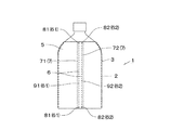
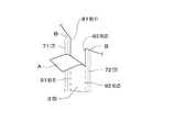
図1に於いて、1は、容器2と、該容器2に熱収縮により装着された熱収縮性筒状ラベル3と、を備える筒状ラベル付き容器を示す。
熱収縮性筒状ラベル3は、熱収縮可能な筒状体5と、前記筒状体5の上端縁から下端縁にかけて縦方向に延びて形成された切断用補助線6と、を有する。
熱収縮性筒状ラベル3は、切断用補助線6の近傍に設けられた接着部7を介して、容器2の外面に部分接着されている。
以下、各構成要素毎に分説し、本発明の熱収縮性筒状ラベル3及び筒状ラベル付き容器1の実施形態を説明する。
In FIG. 1, 1 shows a container with a cylindrical label including a
The heat-shrinkable
The heat-shrinkable
Hereinafter, it explains to every component and explains embodiment of the heat-shrinkable
容器2は、熱収縮性筒状ラベル3が熱収縮装着可能なものであれば特に限定されない。
例えば、容器2は、筒状の胴部と、胴部の上方に形成された肩部と、肩部の上方に形成された首部と、首部の上方に形成された開口部を塞ぐキャップ部と、を有する。図示した容器2は、肩部が上方に向かうに従って窄まった所謂ボトル型容器である。
この容器2の胴部及び肩部の一部に、熱収縮性筒状ラベル3が熱収縮装着されている。
なお、熱収縮性筒状ラベル3は、容器2のキャップ部に装着することもできる(図示せず)。容器2のキャップ部に装着された熱収縮性筒状ラベル3は、特に、キャップシールとも呼ばれる。かかる装着形態の熱収縮性筒状ラベル3は、一般に、容器2のキャップ部の上面周囲から容器2の首部にかけて装着され、キャップ部を封緘する。
The
For example, the
A heat-shrinkable
In addition, the heat-shrinkable
容器2の胴部の形状は、特に限定されず、例えば、略円筒状、4つのパネル面を有する略四角筒状、略円錐台状などでもよい。
容器2の材質も特に限定されず、例えば、合成樹脂、紙、金属、ガラス、陶器などが挙げられる。安価に製造できることから、容器2の材質は、合成樹脂が好ましい。その合成樹脂としては、ポリエチレンテレフタレートなどのポリエステル系樹脂、ポリプロピレンなどのオレフィン系樹脂、スチレン系樹脂などを例示できる。これらの中でも、容器2は、ポリエチレンテレフタレートなどのポリエステル系樹脂の成形品が好ましい(所謂ペットボトルなど)。
容器2に充填される充填物は、特に限定されず、ジュースなどの飲料、液体洗剤や詰替え用シャンプーなどのサニタリー品、消毒用アルコールなどの医薬品、化粧品などの液体、顆粒状の洗剤などの粒状体などが挙げられる。
The shape of the body portion of the
The material of the
The filling material to be filled in the
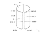
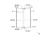
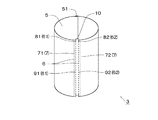
熱収縮性筒状ラベル3は、図2〜図4にも示すように、容器2に熱収縮装着可能な筒状体5を有している。この筒状体5には、その端縁から縦方向に延びる切断用補助線6が形成されている。
筒状体5は、収縮温度(例えば80〜100℃程度)で熱収縮しうる熱収縮性フィルムの両側端部を接着することにより筒状に形成されている。
筒状体5を構成する熱収縮性フィルムは、少なくとも一方向(筒状に形成した際に於ける周方向。以下同じ)に熱収縮しうるものであればその材質は特に限定されず、例えば、ポリエチレンテレフタレートなどのポリエステル系樹脂、ポリプロピレンなどのオレフィン系樹脂、ポリスチレン、スチレン−ブタジエン共重合体などのスチレン系樹脂、環状オレフィン系樹脂、塩化ビニル系樹脂などの熱可塑性樹脂から選ばれる1種、又は2種以上の混合物などからなる合成樹脂製フィルムが挙げられる。また、熱収縮性フィルムとしては、熱収縮性を有する2種以上のフィルムが積層された積層フィルム、熱収縮性を有するフィルムに発泡樹脂シート等の断熱層やその他の機能層が積層された積層フィルムなどを用いることもできる。
As shown in FIGS. 2 to 4, the heat-shrinkable
The
The material of the heat-shrinkable film constituting the
熱収縮性フィルムは、公知の製法で製膜し延伸処理することにより得ることができる。延伸処理は、通常、70〜110℃程度の温度で、一方向に2.0〜8.0倍、好ましくは3.0〜7.0倍程度で主延伸することにより行われる。さらに、フィルムの他方向(筒状に形成した際に於ける縦方向。以下同じ)にも、例えば1.5倍以下の低倍率で延伸処理を行ってもよい。得られたフィルムは、一軸延伸フィルム又は主延伸方向と直交する方向に若干延伸された二軸延伸フィルムとなる。
熱収縮性フィルムの厚みは、特に限定されないが、一般に、20μm〜100μmであり、好ましくは30μm〜80μmである。
A heat-shrinkable film can be obtained by forming into a film by a well-known manufacturing method and extending | stretching. The stretching treatment is usually performed by main stretching at a temperature of about 70 to 110 ° C. in a direction of 2.0 to 8.0 times, preferably about 3.0 to 7.0 times. Furthermore, the film may be stretched at a low magnification of 1.5 times or less, for example, in the other direction of the film (longitudinal direction when formed into a cylindrical shape; the same applies hereinafter). The obtained film becomes a uniaxially stretched film or a biaxially stretched film slightly stretched in a direction orthogonal to the main stretch direction.
The thickness of the heat-shrinkable film is not particularly limited, but is generally 20 μm to 100 μm, preferably 30 μm to 80 μm.
熱収縮性フィルムの一方向に於ける熱収縮率(90℃温水中に10秒間浸漬)は、例えば、約30%以上であり、好ましくは約40%以上である。また、熱収縮性フィルムは他方向に若干熱収縮してもよく、かかる他方向に於ける熱収縮率(90℃温水中に10秒間浸漬)は、約−3〜15%程度である。
但し、熱収縮率(%)=[{(一方向(又は他方向)の元の長さ)−(一方向(又は他方向)の浸漬後の長さ)}/(一方向(又は他方向)の元の長さ)]×100。
The heat shrinkage rate (immersion in 90 ° C. warm water for 10 seconds) in one direction of the heat shrinkable film is, for example, about 30% or more, preferably about 40% or more. The heat-shrinkable film may be slightly heat-shrinked in the other direction, and the heat-shrinkage rate (immersion in 90 ° C. warm water for 10 seconds) in the other direction is about −3 to 15%.
However, thermal shrinkage rate (%) = [{(original length in one direction (or other direction)) − (length after immersion in one direction (or other direction))} / (one direction (or other direction) ) Original length)] × 100.
尚、熱収縮性フィルムには、例えば商品名、商標、絵柄デザインなどの意匠層(図示せず)がグラビア印刷などによって単色又は多色刷りにて形成されている。これにより筒状体5に所望の意匠印刷が表されている。
筒状体5は、上記熱収縮性フィルムの主延伸方向が周方向になるように、熱収縮性フィルムの一側端部を他側端部の外面に重ね合わせて筒状に形成され、該重ね合わせ部分を、溶剤又は接着剤を用いて接着してセンターシール部51が形成されている。
In addition, a design layer (not shown) such as a trade name, a trademark, and a design is formed on the heat-shrinkable film by single color or multicolor printing by gravure printing or the like. Thereby, desired design printing is represented on the
The
この筒状体5の面内には、縦方向に延びる切断用補助線6が形成されている。
切断用補助線6には、筒状体5の端縁から縦方向に延びる切り目、及び、筒状体5の面内において縦方向に延びるミシン目線、が含まれる。
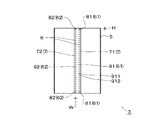
ここで、切り目とは、筒状体5を厚み方向に分断した切込み線であって、筒状体5の端縁から縦方向に所定長さ形成された切込み線である。ミシン目線とは、ミシン針の縫い目跡の如く、筒状体5の厚み方向に貫通する貫通孔(直線状の貫通孔または略円形状の貫通孔)が断続的に刻設された線である。つまり、ミシン目線とは、図4に示すように、貫通孔911と非貫通部912が交互に連なって形成された線である。
切り目の上下長さは、特に限定されないが、好ましくは1mm〜5mmであり、より好ましくは2mm〜4mmである。
また、ミシン目線において、その貫通孔の上下長さと非貫通部の上下長さの比は、好ましくは2:1〜1:10であり、より好ましくは1:7程度である。具体的には、ミシン目線の貫通孔の上下長さは、好ましくは0.5mm〜2mmである。一方、ミシン目線の非貫通部の上下長さは、好ましくは0.5mm〜3.5mmである。
A cutting
The cutting
Here, the cut line is a cut line obtained by dividing the
The vertical length of the cut is not particularly limited, but is preferably 1 mm to 5 mm, and more preferably 2 mm to 4 mm.
In the perforation line, the ratio of the vertical length of the through hole to the vertical length of the non-penetrating portion is preferably 2: 1 to 1:10, and more preferably about 1: 7. Specifically, the vertical length of the perforated through hole is preferably 0.5 mm to 2 mm. On the other hand, the vertical length of the non-penetrating portion of the perforation line is preferably 0.5 mm to 3.5 mm.
本発明においては、切断用補助線6として、前記切り目及びミシン目線を併用してもよいし、切り目又はミシン目線の何れか一方を選択して用いてもよい。切断用補助線6は、切り目及び/又はミシン目線で構成されていることが好ましいが、切断用補助線6は、これ以外(例えば、ハーフカット線など)で構成されていてもよい。
また、切断用補助線6は、筒状体5の1箇所に形成されていてもよいし、筒状体5の周方向に間隔を開けて2箇所形成されていてもよい。
In the present invention, the cut line and perforation line may be used together as the
Further, the cutting
図示した例では、切り目及びミシン目線を併用した切断用補助線6が、筒状体5の周方向に間隔を開けて2箇所形成されている。
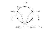
以下、2箇所の切断用補助線6を区別するため、その一方を「第1の切断用補助線61」といい、他方を「第2の切断用補助線62」という。また、第1の切断用補助線61を構成する切り目及びミシン目線を「第1の切り目81」及び「第1のミシン目線91」といい、第2の切断用補助線を構成する切り目及びミシン目線を「第2の切り目82」及び「第2のミシン目線92」という。
In the illustrated example, two
Hereinafter, in order to distinguish the two cutting
第1の切断用補助線61及び第2の切断用補助線62は、筒状体5の縦方向と略平行に延び、それぞれ筒状体5の上端縁から下端縁にかけて形成されている。
第1の切断用補助線61と第2の切断用補助線62は、筒状体5の周方向に所定間隔(この間隔は、例えば、8mm〜20mm程度である)を開けて形成されている。
第1の切断用補助線61は、筒状体5の上端縁及び下端縁において、縦方向に所定長さ切り込まれた上下一対の第1の切り目81,81と、この上下一対の第1の切り目81,81の端に連設された第1のミシン目線91と、から構成されている。
また、第2の切断用補助線62は、筒状体5の上端縁及び下端縁において、縦方向に所定長さ切り込まれた上下一対の第2の切り目82,82と、この上下一対の第2の切り目82,82の端に連設された第2のミシン目線92と、から構成されている。
The first cutting
The first cutting
The first cutting
The second
また、筒状体5の内面には、容器2に接着可能な接着部7が部分的に形成されている。
この接着部7は、筒状体5の上端部及び下端部の少なくとも何れか一方に部分的に形成されている。好ましくは、接着部7は、筒状体5の上端部及び下端部の双方に部分的に形成され、より好ましくは、接着部7は、筒状体5の上端部から下端部にかけて形成される。
図示した例では、接着部7は、前記筒状体5の上端部から下端部まで延びる帯状範囲に形成されている。
接着部7の幅(周方向における長さ)は、特に限定されないが、余りに短いと容器2に対して実質的に接着せず、一方、余りに長くてもその効果に優位性がない。このような観点から、接着部7の幅は、2mm〜10mm程度が好ましい。
In addition, an
The
In the illustrated example, the
The width (the length in the circumferential direction) of the
さらに、上記接着部7は、切断用補助線6の一方側の近傍に形成されている。
切断用補助線6が2箇所形成されている場合には、接着部7は、各切断用補助線6の一方側近傍に形成されている。以下、各接着部7を区別するため、その一方を「第1の接着部71」といい、他方を「第2の接着部72」という。
具体的には、第1の接着部71は、筒状体5の上端部から下端部までの帯状範囲であって、第1の切断用補助線61の一方側(第1の切断用補助線61を基準にして、筒状体5の周方向一方側)近傍に部分的に形成されている。
第2の接着部72は、筒状体5の上端部から下端部までの帯状範囲であって、第2の切断用補助線62の他方側(第2の切断用補助線62を基準にして、筒状体5の周方向他方側(前記周方向一方側とは反対側))近傍に部分的に形成されている。
Further, the
When two
Specifically, the
The
なお、上記近傍とは、第1及び第2の接着部71,72の縁が第1及び第2の切断用補助線61,62と接している状態及び第1及び第2の接着部71,72の縁が第1及び第2の切断用補助線61,62から僅かに離れている状態が含まれる。
第1及び第2の接着部71,72の縁が第1及び第2の切断用補助線61,62から僅かに離れて形成されていると、例えば、筒状体5に第1及び第2のミシン目線91,92を形成する際に用いられるミシン目刻設用の刃に接着剤が付着することを防止できる。
第1及び第2の接着部71,72の縁が第1及び第2の切断用補助線61,62から僅かに離れている場合、第1及び第2の接着部の縁と第1及び第2の切断用補助線との間の長さWは、10mm以内であり、好ましくは5mm以内であり、より好ましは0.1mm〜2mmである。前記長さWが余りに大きいと、熱収縮性筒状ラベル3の切断時に摘み部を引き出した際、非摘み部が摘み部に追従して外側へ膨れ易くなるからである。
In addition, the said vicinity is the state in which the edge of the 1st and
When the edges of the first and
When the edges of the first and second
第1及び第2の接着部71,72は、筒状体5の上端縁及び下端縁に至るまで形成されていてもよい。
もっとも、第1及び第2の接着部71,72は、筒状体5の上端縁及び下端縁の少なくとも何れか一方から僅かに間隙を開けて形成されていることが好ましく、さらに、筒状体5の上端縁及び下端縁から僅かに間隙を開けて形成されていることがより好ましい。
このように第1及び第2の接着部71,72が筒状体5の上端縁及び下端縁から僅かに間隙を開けて形成されていると、長尺状筒状ラベルを切断する際に不良品が生じることを防止できる。すなわち、熱収縮性筒状ラベル3は、通常、長尺状筒状ラベル(長尺状の熱収縮性フィルムを筒状に形成したもの)をロール状に巻いたロール体の形態で提供され、容器に装着する前に、切断用刃を用いて前記長尺状筒状ラベルを所定長さに切断することによって得られる。この切断箇所が、得られる熱収縮性筒状ラベル3の上下端縁に相当する。そして、熱収縮性筒状ラベル3の上下端縁にまで第1及び第2の接着部71,72が形成されていると、切断用刃の押圧によって筒状ラベルの内面が前記接着部71,72を介して接着し得る。このように内面が部分接着した熱収縮性筒状ラベルは、容器に外嵌する際に開口不良を生じる。この点、上記のように、第1及び第2の接着部71,72が筒状体5の上端縁及び下端縁から僅かに間隙を開けて形成されていると、開口不良を生じない熱収縮性筒状ラベル3を得ることができる。
さらに、第1及び第2の接着部71,72が筒状体5の上端縁及び下端縁から僅かに間隙を開けて形成されていると、装着された熱収縮性筒状ラベル3の上端縁近傍及び下端縁近傍が容器2に接着しないので、筒状体5(熱収縮性筒状ラベル3)の上端縁又は下端縁を摘み易くなる。
前記間隙の長さHは、特に限定されないが、好ましくは10mm以下であり、より好ましくは3mm以下である。前記間隙の長さHの下限は、通常、0.5mm以上である。
The first and second
However, the first and second
If the first and second
Further, when the first and second
The length H of the gap is not particularly limited, but is preferably 10 mm or less, more preferably 3 mm or less. The lower limit of the gap length H is usually 0.5 mm or more.
接着部7(第1及び第2の接着部71,72)は、筒状体5の内面の所定範囲に、接着剤を塗工することにより形成できる。前記接着剤としては、例えば、感熱性接着剤を用いることが好ましい。
感熱性接着剤は、室温では接着性を示さず且つ加熱されることによって接着性を発現しうる接着剤である。感熱性接着剤としては、熱収縮性筒状ラベル3の収縮温度(例えば、80〜100℃程度)で接着力が発現するものを用いることが好ましい。かかる感熱性接着剤を用いれば、熱収縮性筒状ラベル3を熱収縮させるために加える熱で接着剤が活性化し、容器2に接着しえる。
The bonding part 7 (first and
The heat-sensitive adhesive is an adhesive that does not exhibit adhesiveness at room temperature and can exhibit adhesiveness when heated. As the heat-sensitive adhesive, it is preferable to use an adhesive that exhibits an adhesive force at the shrinkage temperature (for example, about 80 to 100 ° C.) of the heat-shrinkable
感熱性接着剤の種類は特に限定されず、例えば、ディレードタック型感熱接着剤、パートコート型感熱接着剤、ホットメルト型接着剤などを用いることができる。
ディレードタック型感熱接着剤は、室温で接着性を示さず、加熱することによって活性化して接着性を示し且つ冷却後長時間に亘ってそれが持続するものであり、グラビアコーティングなどの印刷によって塗工可能な接着剤である。ディレードタック型感熱接着剤としては、例えば、エチレン−酢酸ビニル共重合体、酢酸ビニル−アクリル酸エステル共重合体、合成ゴムなどのベース樹脂に粘着付与剤及び固体可塑剤が配合されたエマルジョン型のものなどが例示される。
パートコート型感熱接着剤は、室温で接着性を示さず、加熱によって接着性を示し、例えば、エチレン−酢酸ビニル共重合体などの熱接着性樹脂と粘着付与剤などを有機溶剤などに溶解又は分散させた溶液を、グラビアコーティングなどの印刷によって塗工可能な接着剤であり、塗工後乾燥して使用するものである。
ホットメルト型接着剤は、常温で接着性を示さず、加熱することによって接着可能となるものであり、加熱溶融することによって塗工可能な接着剤である。ホットメルト型接着剤としては、例えば、エチレン−酢酸ビニル共重合体やエチレンアクリル酸共重合体などのエチレン系樹脂、スチレン−ブタジエンブロック共重合体などのベース樹脂に粘着付与剤などの添加剤が配合されたものが例示される。
The type of the heat-sensitive adhesive is not particularly limited, and for example, a delayed tack type heat-sensitive adhesive, a part coat type heat-sensitive adhesive, a hot-melt type adhesive, or the like can be used.
A delayed tack-type heat-sensitive adhesive does not exhibit adhesiveness at room temperature, is activated by heating to exhibit adhesiveness, and persists for a long time after cooling, and is applied by printing such as gravure coating. It is a workable adhesive. Examples of the delayed tack type heat-sensitive adhesive include an emulsion type in which a tackifier and a solid plasticizer are blended with a base resin such as an ethylene-vinyl acetate copolymer, a vinyl acetate-acrylic acid ester copolymer, and a synthetic rubber. The thing etc. are illustrated.
The part coat type heat-sensitive adhesive does not show adhesiveness at room temperature, but shows adhesiveness by heating. For example, a heat-adhesive resin such as ethylene-vinyl acetate copolymer and a tackifier are dissolved in an organic solvent or the like. The dispersed solution is an adhesive that can be applied by printing such as gravure coating, and is used after drying after coating.
The hot-melt adhesive does not exhibit adhesiveness at room temperature, and can be bonded by heating, and is an adhesive that can be applied by heating and melting. Examples of hot melt adhesives include additives such as tackifiers to base resins such as ethylene resins such as ethylene-vinyl acetate copolymer and ethylene acrylic acid copolymer, and styrene-butadiene block copolymers. What was mix | blended is illustrated.
本発明に於いては、所望範囲に簡易に塗工できることから、印刷塗工可能な感熱性接着剤、例えば、上記ディレードタック型感熱接着剤やパートコート型感熱接着剤などを用いることが好ましい。 In the present invention, since it can be easily applied in a desired range, it is preferable to use a heat-sensitive adhesive that can be applied by printing, for example, the above-described delayed tack-type heat-sensitive adhesive or part-coat-type heat-sensitive adhesive.
接着部7を構成する接着剤は、熱収縮性筒状ラベル3の切断時に摘み部を引き出した際、接着部7が容器2から剥がれない程度の接着強度を有し、且つ、切断後の熱収縮性筒状ラベル3を容器から完全に除去する際、接着剤が容器2に残存しない程度の接着強度を有するものが用いられる。
例えば、接着部7(第1及び第2の接着部71,72)の容器2に対する接着強度は、好ましくは0.1〜2.5N/15mmであり、より好ましくは0.3〜1.5N/15mmである。かかる接着強度を有する接着部7であれば、摘み部を引き出した際に剥がれず、且つ熱収縮性筒状ラベル3を完全に除去した後、接着剤が容器2に残存することを防止できる。
ただし、上記接着強度は、下記測定方法で測定された値をいう。なお、上記接着強度は、熱収縮性筒状ラベルの内面と容器の外面を接着する接着剤の接着強度を意味しているが、容器の外面形状は、様々な形状が存在する。このため、下記測定方法では、平坦状のフィルムを容器の外面と見なして測定している。
The adhesive constituting the
For example, the adhesive strength of the adhesive part 7 (first and second
However, the said adhesive strength says the value measured with the following measuring method. In addition, although the said adhesive strength means the adhesive strength of the adhesive agent which adhere | attaches the inner surface of a heat-shrinkable cylindrical label, and the outer surface of a container, the outer surface shape of a container has various shapes. For this reason, in the following measuring method, it measures by considering a flat film as the outer surface of a container.
<測定方法>
第1被着体(熱収縮性筒状ラベルに相当):横15mm×縦50mmの厚み45μmのポリエチレンテレフタレートフィルム。
第2被着体(容器に相当):横15mm×縦50mmの厚み100μmのポリエチレンテレフタレートフィルム。
第1被着体の裏面の横15mm×縦10mmの範囲に、測定対象となる接着剤を塗工する。第1被着体と第2被着体の縦横を対応させて、第1被着体の裏面を第2被着体の表面に接着剤を介して貼り合わせる。第2被着体を動かないように固定すると共に、第1被着体の下端部に精密万能試験機(島津製作所社製、製品名「島津オートグラフ AGS−50Gロードセルタイプ500N)のチャックを取り付ける(第1被着体の接着部分の下縁とチャックの間の距離は40mmである)。このチャックを引き寄せ、第2被着体に対して約90度方向に第1被着体を引張り(引張り速度:200mm/min。温度:23±2℃。相対湿度:50±5%)、第1被着体が第2被着体から剥離するときの荷重を測定する。ただし、測定は、同一条件で6回行い、6回の荷重の平均値を接着強度とする。
<Measurement method>
First adherend (corresponding to a heat-shrinkable cylindrical label): a polyethylene terephthalate film having a width of 15 mm and a length of 50 mm and a thickness of 45 μm.
Second adherend (corresponding to a container): a polyethylene terephthalate film having a width of 15 mm × length of 50 mm and a thickness of 100 μm.
The adhesive to be measured is applied in a range of 15 mm wide × 10 mm long on the back surface of the first adherend. The back surface of the first adherend is bonded to the surface of the second adherend via an adhesive so that the first and second adherends correspond to each other vertically and horizontally. The second adherend is fixed so as not to move, and a chuck of a precision universal testing machine (manufactured by Shimadzu Corporation, product name “Shimadzu Autograph AGS-50G load cell type 500N) is attached to the lower end of the first adherend. (The distance between the lower edge of the bonded portion of the first adherend and the chuck is 40 mm.) The chuck is pulled and the first adherend is pulled in the direction of about 90 degrees with respect to the second adherend ( (Tensile speed: 200 mm / min, temperature: 23 ± 2 ° C., relative humidity: 50 ± 5%), the load when the first adherend peels off from the second adherend is measured. The test is performed 6 times under the conditions, and the average value of the 6 loads is defined as the adhesive strength.
上記熱収縮性筒状ラベル3を容器2に外嵌し、所定の収縮温度に加熱することにより熱収縮性筒状ラベル3が熱収縮して容器2の外面に密着する。このときに熱で、感熱性接着剤が活性化し、接着部7が容器2の外面に接着する。なお、前記収縮温度の加熱で、感熱性接着剤が十分に活性化しない場合には、別途、感熱性接着剤(接着部7)をスポット的に加熱してもよい。
このようにして、熱収縮装着された熱収縮性筒状ラベル3が接着部7を介して容器2に部分的に接着された上記筒状ラベル付き容器1を得ることができる。
The heat-shrinkable
Thus, the said
かかる筒状ラベル付き容器1から熱収縮性筒状ラベル3を除去する場合、例えば、筒状体5(熱収縮性筒状ラベル3)の上端縁のうち第1及び第2の切り目81,82の間を摘み、この摘み部Aを外側へと引き出す(図5参照)。本実施形態では、第1及び第2の切り目81,82が筒状体5の上端縁に形成されており、さらに、前記第1及び第2の切り目81,82の間は容器2に対して接着されていないので、この間における筒状体5の上端縁を簡単に摘むことができる。なお、熱収縮性筒状ラベル3の切断時、筒状体5の下端縁を摘んで引き出してもよい。
When removing the heat-shrinkable
摘み部Aを外側へ引き出すと、これが容器2から離れるが、前記摘み部Aの両側に於ける非摘み部B,Bは、容器2から離れない。すなわち、筒状体5の上端部であって、第1の切断用補助線61の一方側及び第2の切断用補助線62の他方側は、第1及び第2の接着部71,72を介して容器2に接着されているので、非摘み部B,Bが、摘み部Aに追従して容器2から離れない。
このように摘み部Aが外側へ位置ズレする一方で、非摘み部Bが動かないので、摘み部Aと非摘み部B,Bの境界に存する第1及び第2の切り目81,82(切断用補助線6)に引裂力が作用し、前記切り目81,82の端部に引裂起点が生じる。一旦、引裂起点が生じると、事後、摘み部Aを下方に引き出すことにより、実際の切断線が第1及び第2のミシン目線91,92(第1及び第2の切断用補助線61,62)から外れることなく、これに沿って筒状体5を容易に切断できる。
特に、第1及び第2の接着部71,72が、筒状体5の上端部から下端部までの帯状範囲に形成されているので、筒状体5を切断している途中(筒状体5の上下方向中途部)においても筒状体5が容器2から浮き上がらず、第1及び第2のミシン目線91,92に沿って、筒状体5の上端縁から下端縁まで帯状に容易に切り取ることができる。
When the knob A is pulled out, it is separated from the
Thus, while the knob | pick part A shifts | deviates outside, the non-pick part B does not move, Therefore The 1st and
In particular, since the first and second
なお、本発明の熱収縮性筒状ラベル3及び筒状ラベル付き容器1は、上記実施形態に限定されず、本発明の意図する範囲で、様々な形態に変更することができる。
下記に本発明の熱収縮性筒状ラベル3及び筒状ラベル付き容器1の他の実施形態を示すが、上記実施形態と同様の構成及び効果については説明を省略し、用語及び符号をそのまま援用する場合がある。
In addition, the heat-shrinkable
Although other embodiment of the heat-shrinkable
上記実施形態の熱収縮性筒状ラベル3は、接着部7(第1及び第2の接着部71,72)が、筒状体5の上端部から下端部までの帯状範囲に形成されているが、例えば、図6に示すように、接着部7(第1及び第2の接着部71,72)が、筒状体5の上端部及び下端部に部分的に形成されていてもよい。この場合も接着部7は、(第1及び第2の切断用補助線61,62の間ではなく)第1の切断用補助線61の周方向一方側近傍と第2の切断用補助線62の周方向他方側近傍に形成される。
また、特に図示しないが、接着部7は、筒状体5の上端部又は下端部の何れか一方に部分的に形成されていてもよい。好ましくは、接着部7は、筒状体5の上端部に少なくとも形成される。
In the heat-shrinkable
Further, although not particularly illustrated, the
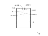
さらに、上記実施形態の熱収縮性筒状ラベル3は、切断用補助線6が筒状体5の上端縁から下端縁まで形成されているが、例えば、図7に示すように、切断用補助線6が筒状体5の上端縁から筒状体5の中途部まで形成されていてもよい。図7に示す熱収縮性筒状ラベル3は、筒状体5の下端縁には第1及び第2の切り目81,82が形成されていない(もっとも、筒状体5の下端縁に第1及び第2の切り目81,82を形成することを除外する意味ではない)。
また、図7に示す熱収縮性筒状ラベル3は、接着部7が筒状体5の上端部に部分的に形成されているが、接着部7が筒状体5の上端部から下端部までの帯状範囲に形成されていてもよい。この点は、図8に示す熱収縮性筒状ラベル3の接着部7についても同様である。
Furthermore, in the heat-shrinkable
Further, in the heat-shrinkable
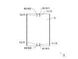
また、上記実施形態の熱収縮性筒状ラベル3は、切断用補助線6が切り目とミシン目線とから構成されているが、切断用補助線6が、切り目又はミシン目線の何れか一方から構成されていてもよい。
例えば、図8に示すように、筒状体5の上端縁に周方向に間隔を開けて第1及び第2の切り目81,82が形成され、且つ筒状体5の下端縁に前記間隔と略同間隔を開けて第1及び第2の切り目81,82が形成されていてもよい。なお、図8に示す熱収縮性筒状ラベル3は、第1及び第2の切り目81,82が筒状体5の上端縁及び下端縁に形成されているが、第1及び第2の切り目81,82が筒状体5の上端縁又は下端縁の何れか一方に形成されていてもよい。好ましくは、第1及び第2の切り目81,82が筒状体5の上端部に少なくとも形成される。
また、特に図示しないが、切断用補助線6がミシン目線のみで構成され、該ミシン目線が筒状体の上端縁から下端縁にまで縦方向に延びて形成されていてもよい。
Further, in the heat-shrinkable
For example, as shown in FIG. 8, first and
In addition, although not particularly illustrated, the cutting
さらに、上記実施形態の熱収縮性筒状ラベル3は、切断用補助線6が、筒状体5の周方向に間隔を開けて2箇所形成されているが、例えば、図9に示すように、切断用補助線6が、筒状体5に1箇所形成されていてもよい。この場合、接着部7は、切断用補助線6の一方側近傍に形成される。このように切断用補助線6が1箇所のみ形成されている場合であっても、その一方側近傍にのみ接着部7が形成されていることにより、前記切断用補助線6の他方側における筒状体5の上端縁を摘み、これを外側に引き出せば、非摘み部(切断用補助線6の一方側における筒状体5の上端部)が外側へ膨らまず、上記実施形態と同様に引裂起点を容易に形成できる。
Furthermore, in the heat-shrinkable
また、上記実施形態の熱収縮性筒状ラベル3は、上端縁が直線状に形成されているが、例えば、図10に示すように、筒状体5の上端縁のうち、第1及び第2の切断用補助線61,62の間を上方へ延出させてもよい。このように延出部10が形成されていると、筒状ラベル付き容器1から熱収縮性筒状ラベル3を除去する際、筒状体5の上端縁(延出部10)がより摘み易くなるので好ましい。
Further, the heat-shrinkable
また、上記実施形態の筒状ラベル付き容器1は、接着部7を有する熱収縮性筒状ラベル3を容器2に熱収縮装着することにより、熱収縮性筒状ラベル3の内面が容器2に部分的に接着されている、すなわち、予め接着剤(接着部7)が熱収縮性筒状ラベル3側に設けられているが、例えば、容器2の所定位置に接着剤を塗工し、これに接着部7を有しない熱収縮性筒状ラベル3を熱収縮装着してもよい。本発明の筒状ラベル付き容器1を構成する場合、接着部7を構成する接着剤を、熱収縮性筒状ラベル3側に塗工してもよいし、容器2側に塗工してもよい。
Moreover, the
1…筒状ラベル付き容器、2…容器、3…熱収縮性筒状ラベル、5…筒状体、6…切断用補助線、61…第1の切断用補助線、62…第2の切断用補助線、7…接着部、71…第1の接着部、72…第2の接着部、81…第1の切り目、82…第2の切り目、91…第1のミシン目線、92…第2のミシン目線、10…延出部
DESCRIPTION OF
Claims (4)
前記筒状体の上端縁及び下端縁から間隔を開けた前記筒状体の上端部及び下端部の内面であって、前記切断用補助線の一方側近傍に、容器に接着可能な接着部が形成されていることを特徴とする熱収縮性筒状ラベル。 In a heat-shrinkable cylindrical label having a cylindrical body that can be heat-shrinkable to a container and having an auxiliary cutting line extending in the vertical direction from an edge of the cylindrical body,
A inner surface of the upper and lower ends of the cylindrical body spaced from the upper edge and the lower edge of the tubular body, on one side near the cutting auxiliary lines, can be bonded to the container adhesion portion A heat-shrinkable cylindrical label characterized in that is formed.
第1の接着部が、第1の切断用補助線の一方側近傍に形成され、且つ、第2の接着部が、第2の切断用補助線の他方側近傍に形成されている請求項1に記載の熱収縮性筒状ラベル。 The adhering portion and the auxiliary cutting line are formed at least two places at intervals in the circumferential direction of the cylindrical body,
The first adhesive portion is formed in the vicinity of one side of the first auxiliary cutting line, and the second adhesive portion is formed in the vicinity of the other side of the second auxiliary cutting line. The heat-shrinkable cylindrical label as described in 2.
Priority Applications (1)
| Application Number | Priority Date | Filing Date | Title |
|---|---|---|---|
| JP2007331475A JP5154909B2 (en) | 2007-12-25 | 2007-12-25 | Heat-shrinkable cylindrical label and container with cylindrical label |
Applications Claiming Priority (1)
| Application Number | Priority Date | Filing Date | Title |
|---|---|---|---|
| JP2007331475A JP5154909B2 (en) | 2007-12-25 | 2007-12-25 | Heat-shrinkable cylindrical label and container with cylindrical label |
Publications (2)
| Publication Number | Publication Date |
|---|---|
| JP2009154877A JP2009154877A (en) | 2009-07-16 |
| JP5154909B2 true JP5154909B2 (en) | 2013-02-27 |
Family
ID=40959326
Family Applications (1)
| Application Number | Title | Priority Date | Filing Date |
|---|---|---|---|
| JP2007331475A Expired - Fee Related JP5154909B2 (en) | 2007-12-25 | 2007-12-25 | Heat-shrinkable cylindrical label and container with cylindrical label |
Country Status (1)
| Country | Link |
|---|---|
| JP (1) | JP5154909B2 (en) |
Families Citing this family (2)
| Publication number | Priority date | Publication date | Assignee | Title |
|---|---|---|---|---|
| JP5552675B2 (en) * | 2010-02-15 | 2014-07-16 | 株式会社フジシール | Labeled container |
| KR102095133B1 (en) * | 2018-12-18 | 2020-03-30 | 박용대 | Heat insulated purified water storage module and water purifying apparatus comprising the same |
Family Cites Families (3)
| Publication number | Priority date | Publication date | Assignee | Title |
|---|---|---|---|---|
| JPH0822250A (en) * | 1994-07-04 | 1996-01-23 | Fuji Seal Co Ltd | Cylindrical body made of heat shrinkable film |
| JPH0966966A (en) * | 1995-08-31 | 1997-03-11 | Fuji Seal Co Ltd | Wrapping body with unsealing tape and wrapping material with unsealing tape |
| JP4405792B2 (en) * | 2003-12-10 | 2010-01-27 | 株式会社フジシールインターナショナル | Heat-shrinkable cylindrical label |
-
2007
- 2007-12-25 JP JP2007331475A patent/JP5154909B2/en not_active Expired - Fee Related
Also Published As
| Publication number | Publication date |
|---|---|
| JP2009154877A (en) | 2009-07-16 |
Similar Documents
| Publication | Publication Date | Title |
|---|---|---|
| US10150891B2 (en) | Shrink films and related combinations and methods | |
| JP6236003B2 (en) | Mount with shrink film | |
| US11756453B2 (en) | Tag attachment by shrink film | |
| JP5204981B2 (en) | Heat-shrinkable cylindrical label and labeled container | |
| JP5154909B2 (en) | Heat-shrinkable cylindrical label and container with cylindrical label | |
| JP2001294282A (en) | Labeled container | |
| JP6249672B2 (en) | Package | |
| JP6202913B2 (en) | Labeled container | |
| JP2012035898A (en) | Labeled container | |
| JP4540110B2 (en) | Heat-shrinkable cylindrical label | |
| JP5052915B2 (en) | Heat-shrinkable cylindrical label and labeled container | |
| JP5552675B2 (en) | Labeled container | |
| JP2017052537A (en) | Container with cylindrical label, and method for manufacturing the same | |
| KR101136625B1 (en) | Display strip | |
| JP6430309B2 (en) | Heat shrinkable label | |
| JP2006030668A (en) | Insulating shrink labels and labeled containers | |
| JP4931040B2 (en) | Heat-shrinkable cylindrical label for cup-shaped containers | |
| JP6308884B2 (en) | Packaging and mount with shrink film | |
| JP4498832B2 (en) | Shrink wrapping material, shrink wrapping material manufacturing method and shrink wrapping material manufacturing apparatus | |
| JP6345484B2 (en) | Package | |
| JP2016009148A (en) | Cylindrical label and container with label | |
| KR20190101968A (en) | Usually a container and its manufacturing method | |
| JP6591836B2 (en) | Heat-shrinkable cylindrical label with label and container with label | |
| JP2013203459A (en) | Shrink film, shrink film with mount, and packaging body | |
| JP4363028B2 (en) | Hold tool for bottle opening cap |
Legal Events
| Date | Code | Title | Description |
|---|---|---|---|
| A621 | Written request for application examination |
Free format text: JAPANESE INTERMEDIATE CODE: A621 Effective date: 20101104 |
|
| A977 | Report on retrieval |
Free format text: JAPANESE INTERMEDIATE CODE: A971007 Effective date: 20120614 |
|
| A131 | Notification of reasons for refusal |
Free format text: JAPANESE INTERMEDIATE CODE: A131 Effective date: 20120622 |
|
| A521 | Request for written amendment filed |
Free format text: JAPANESE INTERMEDIATE CODE: A523 Effective date: 20120809 |
|
| TRDD | Decision of grant or rejection written | ||
| A01 | Written decision to grant a patent or to grant a registration (utility model) |
Free format text: JAPANESE INTERMEDIATE CODE: A01 Effective date: 20121130 |
|
| A61 | First payment of annual fees (during grant procedure) |
Free format text: JAPANESE INTERMEDIATE CODE: A61 Effective date: 20121206 |
|
| FPAY | Renewal fee payment (event date is renewal date of database) |
Free format text: PAYMENT UNTIL: 20151214 Year of fee payment: 3 |
|
| R150 | Certificate of patent or registration of utility model |
Ref document number: 5154909 Country of ref document: JP Free format text: JAPANESE INTERMEDIATE CODE: R150 Free format text: JAPANESE INTERMEDIATE CODE: R150 |
|
| FPAY | Renewal fee payment (event date is renewal date of database) |
Free format text: PAYMENT UNTIL: 20151214 Year of fee payment: 3 |
|
| R250 | Receipt of annual fees |
Free format text: JAPANESE INTERMEDIATE CODE: R250 |
|
| R250 | Receipt of annual fees |
Free format text: JAPANESE INTERMEDIATE CODE: R250 |
|
| R250 | Receipt of annual fees |
Free format text: JAPANESE INTERMEDIATE CODE: R250 |
|
| R250 | Receipt of annual fees |
Free format text: JAPANESE INTERMEDIATE CODE: R250 |
|
| R250 | Receipt of annual fees |
Free format text: JAPANESE INTERMEDIATE CODE: R250 |
|
| R250 | Receipt of annual fees |
Free format text: JAPANESE INTERMEDIATE CODE: R250 |
|
| LAPS | Cancellation because of no payment of annual fees |