JP5153300B2 - antenna - Google Patents
antenna Download PDFInfo
- Publication number
- JP5153300B2 JP5153300B2 JP2007290036A JP2007290036A JP5153300B2 JP 5153300 B2 JP5153300 B2 JP 5153300B2 JP 2007290036 A JP2007290036 A JP 2007290036A JP 2007290036 A JP2007290036 A JP 2007290036A JP 5153300 B2 JP5153300 B2 JP 5153300B2
- Authority
- JP
- Japan
- Prior art keywords
- antenna
- conductor
- length
- loop
- loop antenna
- Prior art date
- Legal status (The legal status is an assumption and is not a legal conclusion. Google has not performed a legal analysis and makes no representation as to the accuracy of the status listed.)
- Active
Links
Images


Classifications
-
- H—ELECTRICITY
- H01—ELECTRIC ELEMENTS
- H01Q—ANTENNAS, i.e. RADIO AERIALS
- H01Q1/00—Details of, or arrangements associated with, antennas
- H01Q1/27—Adaptation for use in or on movable bodies
- H01Q1/32—Adaptation for use in or on road or rail vehicles
- H01Q1/325—Adaptation for use in or on road or rail vehicles characterised by the location of the antenna on the vehicle
-
- H—ELECTRICITY
- H01—ELECTRIC ELEMENTS
- H01Q—ANTENNAS, i.e. RADIO AERIALS
- H01Q1/00—Details of, or arrangements associated with, antennas
- H01Q1/12—Supports; Mounting means
- H01Q1/1271—Supports; Mounting means for mounting on windscreens
-
- H—ELECTRICITY
- H01—ELECTRIC ELEMENTS
- H01Q—ANTENNAS, i.e. RADIO AERIALS
- H01Q7/00—Loop antennas with a substantially uniform current distribution around the loop and having a directional radiation pattern in a plane perpendicular to the plane of the loop
Description
本発明はアンテナに関し、特に、自動車等の車両の誘電体に貼り付けて使用され、円偏波を受信するループアンテナの利得を向上させたアンテナに関する。 The present invention relates to an antenna, and more particularly to an antenna that is used by being attached to a dielectric material of a vehicle such as an automobile, and that improves the gain of a loop antenna that receives circularly polarized waves.
従来から、自動車等の車両には、移動中にも電波の受信等を可能にするアンテナが搭載されている。一般に、車両が受信する電波は、長年に渡ってAMラジオ用の中波(MW)とFMラジオ用やアナログテレビ用の超短波(VHF)や極超短波(UHF)が主なものであった。 Conventionally, a vehicle such as an automobile is equipped with an antenna that enables reception of radio waves while moving. In general, the radio waves received by vehicles have been mainly AM waves for AM radio (MW), FM radio and analog television for ultra high frequency (VHF) and ultra high frequency (UHF) for many years.
ところが近年、車両に搭載されるアンテナの種類が、高周波帯のGPS(グローバル・ポジショニング・システム:全地球測位システム)用のアンテナ、あるいは地上波ディジタルテレビ放送用の電波を受信するアンテナ(以後DTVアンテナという)が主流になりつつある。 However, in recent years, the type of antenna mounted on a vehicle is a high-frequency GPS (global positioning system) antenna or an antenna that receives radio waves for terrestrial digital television broadcasting (hereinafter referred to as a DTV antenna). Is becoming mainstream.
このように車両に搭載されるアンテナで受信すべきGPS用の電波、或いは地上波ディジタルテレビ放送用の電波には円偏波が使用されている。そして、従来の円偏波アンテナにはパッチアンテナが多く利用されていた。ところが、このパッチアンテナは車両の屋根に設置して使用され、見栄えが悪いので、最近では車両の窓に貼り付けて使用するフィルムアンテナが実用化されている。(例えば、特許文献1参照)。
また、本出願人は、前述のように車両に搭載されるアンテナの種類が増えることに対して、1つのフィルムの上に複数のアンテナを配置した統合アンテナを、特許文献2〜特許文献6において提案した。以下に特許文献2〜6で提案した統合アンテナの内容を示す。(特許文献2)ループアンテナとTVアンテナを備えた統合アンテナ(図7)
(特許文献3)ループアンテナとTVアンテナ2つを備えた統合アンテナ(図3−8)
(特許文献4)・ループアンテナとTVアンテナ2つを備えた統合アンテナ(図1)
・ループアンテナとTVアンテナ1つを備えた統合アンテナ(図3)
(特許文献5)・2つのループアンテナを備えた統合アンテナ(図3、11)
・ループアンテナ2つとTVアンテナ1つを備えた統合アンテナ(図8)
・ループアンテナとモノポールアンテナを備えた統合アンテナ(図9,10)
・ループアンテナとデジタルTVアンテナを備えた統合アンテナ(図12)
(特許文献6)・2つのループアンテナを備えた統合アンテナ(図9)
・ループアンテナ2つとモノポールアンテナを備えた統合アンテナ(図10)
As described above, circularly polarized waves are used for radio waves for GPS to be received by an antenna mounted on a vehicle or radio waves for terrestrial digital television broadcasting. Many patch antennas have been used for conventional circularly polarized antennas. However, since this patch antenna is used by being installed on the roof of a vehicle and has a poor appearance, a film antenna that is used by being attached to a window of a vehicle has recently been put into practical use. (For example, refer to Patent Document 1).
In addition, in the patent document 2 to
(Patent Document 3) Integrated antenna including a loop antenna and two TV antennas (FIGS. 3-8)
(Patent Document 4) Integrated antenna with loop antenna and two TV antennas (Fig. 1)
-Integrated antenna with loop antenna and one TV antenna (Figure 3)
(Patent Document 5) Integrated antenna with two loop antennas (Figs. 3 and 11)
Integrated antenna with two loop antennas and one TV antenna (Figure 8)
・ Integrated antenna with loop antenna and monopole antenna (Figs. 9 and 10)
Integrated antenna with loop antenna and digital TV antenna (Figure 12)
(Patent Document 6)-Integrated antenna with two loop antennas (Fig. 9)
・ Integrated antenna with two loop antennas and monopole antenna (Figure 10)
しかしながら、特許文献1等に開示されているアンテナは、受信性能が十分でなかった。
However, the antenna disclosed in
そこで、本発明は、利得を大きくすることができ、受信性能を向上させることができるアンテナを提供することを目的としている。 Accordingly, an object of the present invention is to provide an antenna that can increase the gain and improve the reception performance.
前記目的を達成する本発明の第1の形態のアンテナは、2つの給電端子を備えたループアンテナと、ループアンテナの近傍に配置され、ループアンテナのアンテナ導体に対して独立した導体から構成された無給電素子と、ループアンテナ及び前記無給電素子の周囲を、隙間なく完全に取り囲んで配置された環状に連続する導体とを備え、導体の長さは、ループアンテナの実質的な全周の長さの3倍であり、導体の形状は矩形状であり、隣り合う2辺の比が1:2又は2:1であることを特徴としている。
前記目的を達成する本発明の第2の形態のアンテナは、2つの給電端子を備えたループアンテナと、ループアンテナの近傍に配置され、ループアンテナのアンテナ導体に対して独立した導体から構成された無給電素子と、ループアンテナ及び無給電素子の周囲を、隙間なく完全に取り囲んで配置された環状に連続する導体とを備え、導体の長さは、ループアンテナの実質的な全周の長さの3倍であり、導体の形状は楕円形であり、楕円の長径と短径の比が1:1〜1:2の範囲であることを特徴としている。
The antenna of the first form of the present invention that achieves the above object is composed of a loop antenna having two feeding terminals and a conductor arranged in the vicinity of the loop antenna and independent of the antenna conductor of the loop antenna. A parasitic element, and a loop antenna and an annular continuous conductor arranged so as to completely surround the periphery of the parasitic element without a gap , and the length of the conductor is substantially the entire length of the loop antenna. The conductor is rectangular, and the ratio of two adjacent sides is 1: 2 or 2: 1 .
The antenna of the second form of the present invention that achieves the above object is composed of a loop antenna having two feeding terminals and a conductor that is arranged in the vicinity of the loop antenna and independent of the antenna conductor of the loop antenna A parasitic element and an annular continuous conductor arranged so as to completely surround the loop antenna and the parasitic element without gaps, and the length of the conductor is substantially the length of the entire circumference of the loop antenna. The shape of the conductor is elliptical, and the ratio of the major axis to the minor axis of the ellipse is in the range of 1: 1 to 1: 2.
本発明のアンテナによれば、構造が簡単で、円偏波を送信及び/又は受信することができる受信性能の良いアンテナが提供される。 According to the antenna of the present invention, an antenna having a simple structure and good reception performance capable of transmitting and / or receiving circularly polarized waves is provided.
以下添付図面を用いて本発明に係る実施の形態を具体的な実施例に基づいて詳細に説明する。なお、一般に、アンテナは電波の送信と受信の両方を行い得るものであるが、以下に示す実施例では、説明を簡単にするために、アンテナが電波を受信する場合についてのみ説明し、アンテナが電波を送信する場合についてはその説明を省略する。アンテナからの電波の送信が本発明に含まれることは言うまでもない。 Embodiments according to the present invention will be described below in detail based on specific examples with reference to the accompanying drawings. In general, an antenna can perform both transmission and reception of radio waves. However, in the following embodiment, only the case where the antenna receives radio waves will be described for the sake of simplicity. Description of the case of transmitting radio waves is omitted. It goes without saying that transmission of radio waves from an antenna is included in the present invention.
図1(a)は、本発明の第1の実施例のGPS用のアンテナ13の構成を示すものである。この実施例のGPS用のアンテナ13はループアンテナを使用しており、シート状の透明フィルム14の上に、矩形のアンテナ導体15と、このアンテナ導体15には電気的に接続しない無給電素子16とが形成されていて、GPS衛星からの円偏波を受信し、また、円偏波を送信可能である。一方、アンテナ導体15の両端部には給電端子17,18があり、この給電端子17,18に後述するコネクタが接続される。アンテナ導体15、無給電素子16、及び給電端子17,18は、導電性インク、或いは銅箔等の導体によってシート状の透明フィルム14の上に形成される。
FIG. 1A shows the configuration of the
この実施例のGPS用のアンテナ13には、アンテナ導体15、無給電素子16、及び給電端子17,18の周囲に、矩形で環状の線状導体19が同じく導電性インク、或いは銅箔等の導体によってシート状の透明フィルム14の上に形成されている。このGPS用のアンテナ13をガラスのような誘電体の上に配置する場合には、矩形のアンテナ導体15の一辺の長さZが30mm程度であり、無給電素子16の離反部Pの長さが40mm程度、平行部Qの長さが20mm程度である。また、横方向の環状の線状導体19の長さXを90mm程度とし、縦方向の環状の線状導体19の長さYを90mm程度とすることができる。この場合の環状の線状導体19の全長は180mm程度であり、内部のループアンテナの大きさに応じて縦横比を変更可能である。また、環状の線状導体19の最適な長さ及びGPS用のアンテナ13のサイズは、GPS用のアンテナ13を取り付ける誘電体の誘電率によって決定される。
In the
例えば、GPS用のアンテナ13を発泡樹脂の上に設置する場合は、GPS用のアンテナ13のループの1辺の長さZを50mm程度、無給電素子16の離反部Pの長さを60mm程度、平行部Qの長さを30mm程度とすれば良い。
For example, when the
矩形で環状の線状導体19をアンテナ導体15、無給電素子16、及び給電端子17,18の周囲に配置する場合、環状の線状導体19の全長(2X+2Y)は、アンテナ導体15の全長(4Z)の3倍程度(2.7〜3.3倍ほど)とすると、GPS用のアンテナ13の利得が大きくなる。また、環状の線状導体19の横方向の長さXに対する縦方向の長さYの比(X:Y)は、1:1が最適であるが、1:2〜2:1の範囲でも利得を上昇させる効果がある。
When the rectangular
以上のように構成されたGPS用のアンテナ13は、例えば図1(b)に示すように、自動車60のフロントガラス1の上端部近傍に設置することができる。この図には透明フィルムの図示は省略してある。GPS用のアンテナ13にはコネクタ20と同軸ケーブル22からなる給電回路が接続される。同軸ケーブル22は、自動車60のAピラー3に沿って配設され、本図には図示しないデジタルTVチューナに接続される。8は自動車のインストルメントパネル9に設置されたカーナビゲーション装置であり、チューナからの画像信号が入力される。
The
以上のように、アンテナ導体15、無給電素子16、及び給電端子17,18の周囲に、矩形で環状の線状導体19が配置されたGPS用のアンテナ13を、自動車60のフロントガラス1の上端部近傍に設置した場合、図11に示すように、環状の線状導体19がない場合に比べて約2dBの利得上昇効果が得られる。
As described above, the
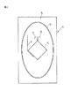
図2は、本発明の第2の実施例のGPS用のアンテナ13の構成を示すものである。この実施例のGPS用のアンテナ13もループアンテナを使用しており、シート状の透明フィルム14の上に、矩形のアンテナ導体15と、このアンテナ導体15には電気的に接続しない無給電素子16とが形成されている。アンテナ導体15の両端部には給電端子17,18があり、この給電端子17,18にコネクタが接続されることも第1の実施例と同様である。
FIG. 2 shows the configuration of the
第1の実施例では、アンテナ導体15、無給電端子16、及び給電端子17,18は、矩形の環状の線状導体19で囲まれていたが、第2の実施例では、縦長の楕円形の環状の線状導体19で囲まれている。ここでも環状の線状導体19の全長は、アンテナ導体15の全長(4Z)の3倍程度とすると、GPS用のアンテナ13の利得が大きくなる。またこの場合は、楕円状の線状導体19の短径の長さXに対する長径の長さYの比(X:Y)は、1:1が最適であるが、1:1〜1:2の範囲でも利得を上昇させる効果がある。
In the first embodiment, the
なお、第1の実施例のアンテナ13は、図3(c)に示すように、環状の線状導体19の横方向の長さXに対する縦方向の長さYの比(X:Y)を1:1程度とすることが好ましい。しかしながら、このX:Yの比率を、辺Xと辺Yの和を変更することなく、辺Xの長さを長くし、逆に辺Yの長さを短くして、図3の(b)に示す状態のアンテナ13としても、環状の線状導体19がない状態のアンテナ13よりも利得は大きくなる。同様に、X:Yの比率を、辺Xと辺Yの和を変更することなく、辺Xの長さを更に長くし、逆に辺Yの長さを更に短くして、図3の(a)に示す状態のアンテナ13(X:Y=2:1)としても環状の線状導体19がない状態のアンテナ13よりも利得は大きくなる。また、前述のX:Yの比率を、辺Xと辺Yの和を変更することなく、辺Xの長さを短くしていき、辺Yの長さを長くしていって、図3の(d)または(e)に示す状態のアンテナ13としても、環状の線状導体19がない状態のアンテナ13よりも利得は大きくなる。そして、図3の(e)に示す状態のアンテナ13のように、X:Yの比率を1:2とすると、利得が図3の(a)に示したアンテナ13と変わらなくなる。
The
図4(a)、(b)は、図1(b)に示したコネクタ20の外観、及びコネクタ20を分解した状態を示すものである。図4(a)に示すように、コネクタ20は、インナケース21とアウタケース25を合わせて構成されており、インナケース21の表面(アンテナ10への取り付け面)には2つの開口部21A,21Bがあり、ばね性を有する接続端子31,32がこの開口部21A,21Bから突出している。コネクタ20は、そのインナケース21の表面が両面テープなどの粘着材によって、給電端子17,18の上に固定される。
4A and 4B show the appearance of the
接続端子31,32は、図4(b)に示すように、インナケース21とアウタケース25に内蔵された回路基板(誘電体基板)30の一方の面上に取り付けられており、この回路基板30に同軸ケーブル22が接続している。回路基板30の他方の面上には後述する集積回路40が実装されている。一般に、接続端子31がホット側(信号伝達側)の端子であり,接続端子32がアース側の端子である。
As shown in FIG. 4B, the
図5(a)は、図4(b)に示したコネクタ20の内部にある回路基板30の一般的な構成を、インナケース21とアウタケース25を除いて示すものである。接続端子31,32は回路基板30の裏面側に取り付けられており、スルホール33,34で回路基板30の表側に導かれる。この例では、スルホール33は、回路基板30の表側に実装されている集積回路40の入力端子に接続され、スルホール34は、同軸ケーブル22のアース線(外側導体)22Bに接続している。集積回路40はアンテナで受信された信号に対して増幅等の処理を施すものであり、処理された信号は、同軸ケーブル22の中心導体(内側導体)22Aに出力される。
FIG. 5A shows a general configuration of the
図5(b)は図5(a)に示した集積回路40の内部構成を示すものである。集積回路40の内部にはアンテナ10に接続するフィルタ41、フィルタ41から出力される信号を増幅するアンプ42、アンプ42から出力される信号帯域を定めるフィルタ43があり、このフィルタ43は直流を阻止するコンデンサ44を介して同軸ケーブル22の中心導体22Aに接続している。この同軸ケーブル22は電源重畳ケーブルであり、重畳された電源電圧(直流)は、交流成分を遮断するコイル45を通じてアンプ42に供給される。
FIG. 5B shows the internal configuration of the
図5(c)は、図5(a)に示したコネクタ20とは異なる回路基板30の構成を、インナケース21とアウタケース25を除いて示すものである。図5(a)に示したコネクタ20の回路基板30では、接続端子31がホット側(信号伝達側)の端子であり、スルホール33で集積回路40の入力端子に接続されており、接続端子32がアース側の端子であって、スルホール34で同軸ケーブル22のアース線22Bに接続していた。一方、図5(c)に示したコネクタ20の回路基板30は、接続端子31がアース側の端子であり、スルホール34で同軸ケーブル22のアース線22Bに接続しており、接続端子32がホット側(信号伝達側)の端子であって、スルホール33で集積回路40の入力端子に接続されている。このように、接続端子31をアース側の端子、接続端子32をホット側の端子とすることも可能である。
FIG. 5C shows a configuration of the
第1の実施例において、アンテナ導体15、無給電端子16、及び給電端子17,18を囲む矩形の環状の線状導体19は、全周に渡って導体が連続していなくとも効果があることが実験の結果分かった。そして、GPS用のアンテナ13の給電端子17,18を囲む矩形の環状の線状導体19は、その全長がDTVアンテナを構成するループアンテナのループ長に近いことが分かった。そこで本発明者らは、矩形の環状の線状導体19の一部を切り欠いて、切り欠いた端部に図6(a)に示すように給電端子11,12を形成し、矩形の環状の線状導体19をDTVアンテナ10Aとすることを案出した。
In the first embodiment, the rectangular annular
この場合、図6(a)に示すGPS用のアンテナ13とDTVアンテナ10Aとが一緒になった統合アンテナ10A,13を、自動車60のフロントガラス1の上端部の左隅に配置する。これに加えて、図6(b)に示すDTVアンテナ10D,図10(c)に示すDTVアンテナ(給電端子11,12を一方の側にオフセットしたもの)10B、及び図10(c)に示すDTVアンテナ10Dに対して鏡像関係にあるDTVアンテナ10Cを、図6(d)に示すように、自動車60のフロントガラス1の上端部に、統合アンテナ10A,13に並べて配置して、アンテナ装置を構成することができる。なお、図6(d)に示すアンテナ装置では、各アンテナの給電端子にコネクタがそれぞれ接続されるが、ここではコネクタと同軸ケーブルからなる給電回路の図示は省略してある。
In this case, the
図7は、図6(d)に示した各アンテナ10A,13,10B,10C,10Dからなるアンテナ装置と、車両に搭載されたナビゲーション装置8との接続を示す回路図である。この実施例では、TVチューナ5がナビゲーション装置8に内蔵されているが、TVチューナ5はナビゲーション装置8と別体になっていても良い。
FIG. 7 is a circuit diagram showing a connection between the antenna device including the
この実施例では、統合アンテナ10A、13の中のアンテナ導体19と、フィルムアンテナ10B,10C、10DがDTVアンテナであり、統合アンテナ10A、13の中のアンテナ導体15がGPS用のアンテナである。これらのフィルムアンテナ10A,10B,10C,10Dで受信されたDTV用の信号は、前述のコネクタに内蔵された増幅等を行う集積回路40を介してケーブル22によってTVチューナ5に導かれ、復調された画像は、ナビゲーション装置8がTVモードの時にその表示器6に表示される。また、フィルムアンテナ10AMに搭載されたGPS用のアンテナ13(アンテナ導体15)で受信されたGPS用の信号は、集積回路40、ケーブル22を介してナビゲーション装置8のECU4に導かれ、自動車の現在位置が検出され、地図情報と共にナビゲーション装置8の表示器6に表示される。
In this embodiment, the
図8(a)は本発明の第3の実施例のアンテナ53の構成を示すものである。第3の実施例のGPS用のアンテナ53もループアンテナを使用しており、シート状の透明フィルム14の上に、矩形のアンテナ導体15と、このアンテナ導体15には電気的に接続しない無給電素子16とが形成されていて、GPS衛星からの円偏波を受信し、また、円偏波を送信可能である。一方、アンテナ導体15の両端部には給電端子17,18があり、この給電端子17,18に後述するコネクタが接続される。アンテナ導体15、無給電端子16、及び給電端子17,18が、導電性インク、或いは銅箔等の導体によってシート状の透明フィルム14の上に形成される点は第1の実施例と同じである。
FIG. 8 (a) shows the configuration of the
第3の実施例のGPS用のアンテナ53では、アンテナ導体15、無給電素子16、及び給電端子17,18の周囲に、第1の実施例で説明した矩形で環状の線状導体19と同じ寸法の開口部を備える金属板51が透明フィルム14の上に取り付けられる。第3の実施例では、金属板51の開口部の寸法が同じであれば、金属板51の大きさは特に限定されない。例えば、GPS用のアンテナ13は、矩形のアンテナ導体15の一辺の長さZが32mm程度である場合は、金属板51の開口部の横方向の長さは95mm程度、縦方向の長さは95mm程度で良い。
In the
図8(b)は本発明の第3の実施例のアンテナ53の変形例を示すものである。この変形例のアンテナ53が、図8(a)で説明した第3の実施例のアンテナ53と異なる点は、金属板51の代わりに金属メッシュ52がシート状の透明フィルム14に取り付けられている点のみである。この変形例のアンテナ53の性能は第3の実施例のアンテナ53と大差ない。
FIG. 8B shows a modification of the
図9(a)は本発明の第1又は第3の実施例のアンテナ13,53を自動車のバックミラー(インナリヤビューミラー)35に貼り付けた使用例を示すものである。また、図9(b)は本発明の第1又は第3の実施例のアンテナ13,53を自動車のバックミラー35に埋め込んだ使用例を示すものである。このような取付位置により、本発明のアンテナ13,53は、自動車の前方上方から到来する電波を効率よく受信することができる。
FIG. 9A shows an example of use in which the
図10(a)、(b)は本発明のアンテナ13,53の自動車への搭載位置の別の例として、アンテナ13,53をワゴン型自動車37のリヤスポイラー36に内蔵させた例を示している。この位置におけるアンテナ13,53の指向性は、リヤスポイラー36に内蔵させたアンテナ13,53の取り付け角度によって変化させることができる。図10(a)に示すように、アンテナ13,53を後方に傾斜させてリヤスポイラー37に内蔵させると、アンテナ13,53の指向性は自動車37の後方上方となる。また、図10(b)に示すように、アンテナ13,53を前方に傾斜させてリヤスポイラー36に内蔵させると、アンテナ13,53の指向性は自動車37の前方上方となる。
FIGS. 10A and 10B show an example in which the
本発明のアンテナ13,53は、これらの取り付け位置以外にも、車両の樹脂製のルーフトップ等にも取り付けることが可能である。本発明のアンテナ13,53に使用できるGPS用のアンテナ13のアンテナ導体の形状、及び、無給電素子16の数と配置は、前述の実施例に限定されるものではない。
The
1 フロントガラス
3 Aピラー
8 カーナビ装置
10A,10B,10C,10D DTVアンテナ
11,12、17,18 給電端子
13 GPS用アンテナ
15 アンテナ導体
16 無給電素子
19 環状の線状導体
20 コネクタ
22 同軸ケーブル
14、24 シート状の透明フィルム
30 回路基板
40 集積回路
60 自動車
DESCRIPTION OF
Claims (6)
前記ループアンテナの近傍に配置され、前記ループアンテナのアンテナ導体に対して独立した導体から構成された無給電素子と、
前記ループアンテナ及び前記無給電素子の周囲を、隙間なく完全に取り囲んで配置された環状に連続する導体とを備え、
前記導体の長さは、前記ループアンテナの実質的な全周の長さの3倍であり、
前記導体の形状は矩形状であり、隣り合う2辺の比が1:2〜2:1の範囲であることを特徴とするアンテナ。 A loop antenna with two feed terminals;
A parasitic element that is disposed in the vicinity of the loop antenna and is configured of a conductor independent of the antenna conductor of the loop antenna;
An annular continuous conductor disposed completely surrounding the loop antenna and the parasitic element without a gap ;
The length of the conductor is three times the length of the substantially entire circumference of the loop antenna;
The antenna is characterized in that the shape of the conductor is rectangular and the ratio of two adjacent sides is in the range of 1: 2 to 2: 1 .
前記ループアンテナの近傍に配置され、前記ループアンテナのアンテナ導体に対して独立した導体から構成された無給電素子と、A parasitic element that is disposed in the vicinity of the loop antenna and is configured of a conductor independent of the antenna conductor of the loop antenna;
前記ループアンテナ及び前記無給電素子の周囲を、隙間なく完全に取り囲んで配置された環状に連続する導体とを備え、An annular continuous conductor disposed completely surrounding the loop antenna and the parasitic element without a gap;
前記導体の長さは、前記ループアンテナの実質的な全周の長さの3倍であり、The length of the conductor is three times the length of the substantially entire circumference of the loop antenna;
前記導体の形状は楕円形であり、前記楕円の長径と短径の比が1:1〜1:2の範囲であることを特徴とするアンテナ。The antenna is characterized in that a shape of the conductor is an ellipse, and a ratio of a major axis to a minor axis of the ellipse is in a range of 1: 1 to 1: 2.
前記導体が環状の線状導体であることを特徴とするアンテナ。 The antenna according to claim 1 or 2 ,
An antenna, wherein the conductor is an annular linear conductor.
前記導体が金属板であり、前記ループアンテナ及び前記無給電素子がこの金属板に設けられた開口部内に配置されていることを特徴とするアンテナ。 The antenna according to claim 1 or 2 ,
The antenna is characterized in that the conductor is a metal plate, and the loop antenna and the parasitic element are disposed in an opening provided in the metal plate.
前記ループアンテナ、無給電素子、及び線状導体または金属板がシート状の誘電体の上に形成されていることを特徴とするアンテナ。 The antenna according to claim 3 or 4 , wherein
The antenna, wherein the loop antenna, parasitic element, and linear conductor or metal plate are formed on a sheet-like dielectric.
前記シート状の誘電体は透明なフィルムであることを特徴とするアンテナ。 The antenna according to claim 5 , wherein
The antenna according to claim 1, wherein the sheet-like dielectric is a transparent film.
Priority Applications (5)
| Application Number | Priority Date | Filing Date | Title |
|---|---|---|---|
| JP2007290036A JP5153300B2 (en) | 2007-11-07 | 2007-11-07 | antenna |
| CN200880115252A CN101855780A (en) | 2007-11-07 | 2008-10-21 | Circularly polarized wave receiving antenna |
| US12/739,130 US8994598B2 (en) | 2007-11-07 | 2008-10-21 | Circularly polarized wave reception antenna |
| PCT/JP2008/069395 WO2009060735A1 (en) | 2007-11-07 | 2008-10-21 | Circularly polarized wave receiving antenna |
| TW97142554A TWI433387B (en) | 2007-11-07 | 2008-11-04 | Circular polarized wave receiving antenna |
Applications Claiming Priority (1)
| Application Number | Priority Date | Filing Date | Title |
|---|---|---|---|
| JP2007290036A JP5153300B2 (en) | 2007-11-07 | 2007-11-07 | antenna |
Publications (2)
| Publication Number | Publication Date |
|---|---|
| JP2009118268A JP2009118268A (en) | 2009-05-28 |
| JP5153300B2 true JP5153300B2 (en) | 2013-02-27 |
Family
ID=40625632
Family Applications (1)
| Application Number | Title | Priority Date | Filing Date |
|---|---|---|---|
| JP2007290036A Active JP5153300B2 (en) | 2007-11-07 | 2007-11-07 | antenna |
Country Status (5)
| Country | Link |
|---|---|
| US (1) | US8994598B2 (en) |
| JP (1) | JP5153300B2 (en) |
| CN (1) | CN101855780A (en) |
| TW (1) | TWI433387B (en) |
| WO (1) | WO2009060735A1 (en) |
Families Citing this family (25)
| Publication number | Priority date | Publication date | Assignee | Title |
|---|---|---|---|---|
| US9002565B2 (en) | 2003-03-20 | 2015-04-07 | Agjunction Llc | GNSS and optical guidance and machine control |
| US8583315B2 (en) | 2004-03-19 | 2013-11-12 | Agjunction Llc | Multi-antenna GNSS control system and method |
| JP5269393B2 (en) * | 2007-11-12 | 2013-08-21 | 富士通テン株式会社 | Vehicle antenna device |
| US8184050B2 (en) * | 2008-02-10 | 2012-05-22 | Hemisphere Gps Llc | Antenna alignment and monitoring system and method using GNSS |
| US8299962B2 (en) * | 2009-03-16 | 2012-10-30 | Le Sage Hendrikus A | AISG inline tilt sensor system and method |
| US9046601B2 (en) | 2009-06-15 | 2015-06-02 | Hendrikus A. Le Sage | Handheld antenna attitude measuring system |
| JP5478206B2 (en) * | 2009-11-16 | 2014-04-23 | 株式会社ヨコオ | In-vehicle GPS antenna |
| JP4976511B2 (en) * | 2010-01-21 | 2012-07-18 | 原田工業株式会社 | Circularly polarized antenna |
| JP5499810B2 (en) * | 2010-03-19 | 2014-05-21 | 旭硝子株式会社 | Glass antenna for vehicle and window glass for vehicle |
| US8307535B2 (en) | 2010-07-20 | 2012-11-13 | Hemisphere Gps Llc | Multi-frequency antenna manufacturing method |
| US8686899B2 (en) | 2010-08-26 | 2014-04-01 | Hemisphere GNSS, Inc. | GNSS smart antenna and receiver system with weatherproof enclosure |
| JP2014033243A (en) * | 2010-11-30 | 2014-02-20 | Asahi Glass Co Ltd | Vehicle window glass and antenna |
| TWI473383B (en) * | 2012-11-06 | 2015-02-11 | Configuration antenna with concentrated magnetic field | |
| WO2014133155A1 (en) * | 2013-03-01 | 2014-09-04 | 株式会社フジクラ | Integrated antenna, and manufacturing method thereof |
| WO2014149201A1 (en) * | 2013-03-15 | 2014-09-25 | Agc Automotive Americas R& D, Inc. | Window assembly with transparent regions having a perfoormance enhancing slit formed therein |
| JP6547311B2 (en) * | 2015-01-30 | 2019-07-24 | Agc株式会社 | MIMO antenna and MIMO antenna arrangement structure |
| JP6378152B2 (en) | 2015-09-25 | 2018-08-22 | 矢崎総業株式会社 | Vehicle arrangement structure of planar antenna body |
| KR101827706B1 (en) * | 2016-09-20 | 2018-02-12 | 현대자동차주식회사 | Vehicle and control method for the vehicle |
| JP6894212B2 (en) * | 2016-11-08 | 2021-06-30 | 矢崎総業株式会社 | Planar antenna body |
| JP2018101956A (en) * | 2016-12-21 | 2018-06-28 | トヨタ自動車株式会社 | Vehicle antenna system |
| CN107053967A (en) * | 2016-12-30 | 2017-08-18 | 上海为彪汽配制造有限公司 | Electric wave reception antenna and tire pressure monitor for tire pressure monitor |
| WO2019225321A1 (en) | 2018-05-25 | 2019-11-28 | セントラル硝子株式会社 | Glass antenna for circularly polarized wave reception |
| CN112886232B (en) * | 2019-11-30 | 2022-10-11 | 华为技术有限公司 | Electronic device |
| JPWO2023032187A1 (en) * | 2021-09-06 | 2023-03-09 | ||
| DE102022102502A1 (en) | 2022-02-03 | 2023-08-03 | Dr. Ing. H.C. F. Porsche Aktiengesellschaft | Motor vehicle with a windscreen |
Family Cites Families (22)
| Publication number | Priority date | Publication date | Assignee | Title |
|---|---|---|---|---|
| US1934412A (en) * | 1928-03-24 | 1933-11-07 | Bell Telephone Labor Inc | Radio receiving circuit |
| US4183027A (en) * | 1977-10-07 | 1980-01-08 | Ehrenspeck Hermann W | Dual frequency band directional antenna system |
| JP2543780B2 (en) | 1990-07-23 | 1996-10-16 | コニカ株式会社 | Zoom lenses |
| JP2528517Y2 (en) * | 1990-11-21 | 1997-03-12 | 日本板硝子株式会社 | Window glass antenna |
| JP3431045B2 (en) * | 1995-01-18 | 2003-07-28 | 久松 中野 | Circularly polarized loop antenna |
| DE19922699C2 (en) * | 1999-05-18 | 2001-05-17 | Hirschmann Electronics Gmbh | Antenna with at least one vertical radiator |
| DE10024666A1 (en) * | 2000-05-18 | 2001-11-29 | Bosch Gmbh Robert | Vehicle antenna arrangement |
| US7154449B2 (en) * | 2002-04-25 | 2006-12-26 | Cet Technologies Pte Ltd. | Antenna |
| JP4278589B2 (en) | 2003-08-29 | 2009-06-17 | 富士通テン株式会社 | antenna |
| TWI298958B (en) * | 2003-08-29 | 2008-07-11 | Fujitsu Ten Ltd | Circular polarization antenna and composite antenna including this antenna |
| JP4286163B2 (en) * | 2004-02-19 | 2009-06-24 | 富士通テン株式会社 | Integrated antenna, integrated antenna device, and receiver |
| JP4278534B2 (en) | 2004-02-19 | 2009-06-17 | 富士通テン株式会社 | Circularly polarized antenna, antenna device, and processing device |
| JP2006013696A (en) * | 2004-06-23 | 2006-01-12 | Fujitsu Ten Ltd | Film antenna and navigation system employing the same |
| US7362285B2 (en) * | 2004-06-21 | 2008-04-22 | Lutron Electronics Co., Ltd. | Compact radio frequency transmitting and receiving antenna and control device employing same |
| JP2006080999A (en) * | 2004-09-10 | 2006-03-23 | Fujitsu Ten Ltd | Antenna for television radio wave |
| JP4780957B2 (en) * | 2004-12-27 | 2011-09-28 | 富士通テン株式会社 | Integrated antenna |
| JP4868874B2 (en) * | 2005-03-29 | 2012-02-01 | 富士通テン株式会社 | Loop antenna, antenna system using the antenna, and vehicle equipped with the antenna system |
| CN1841847A (en) * | 2005-03-29 | 2006-10-04 | 富士通天株式会社 | Loop antenna |
| JP4679950B2 (en) | 2005-04-11 | 2011-05-11 | 日本アンテナ株式会社 | Loop antenna |
| JP4478634B2 (en) * | 2005-08-29 | 2010-06-09 | 富士通株式会社 | Planar antenna |
| JP4735368B2 (en) | 2006-03-28 | 2011-07-27 | 富士通株式会社 | Planar antenna |
| JP2007288399A (en) * | 2006-04-14 | 2007-11-01 | Nippon Antenna Co Ltd | Antenna |
-
2007
- 2007-11-07 JP JP2007290036A patent/JP5153300B2/en active Active
-
2008
- 2008-10-21 CN CN200880115252A patent/CN101855780A/en active Pending
- 2008-10-21 WO PCT/JP2008/069395 patent/WO2009060735A1/en active Application Filing
- 2008-10-21 US US12/739,130 patent/US8994598B2/en not_active Expired - Fee Related
- 2008-11-04 TW TW97142554A patent/TWI433387B/en not_active IP Right Cessation
Also Published As
| Publication number | Publication date |
|---|---|
| US20100231468A1 (en) | 2010-09-16 |
| TWI433387B (en) | 2014-04-01 |
| JP2009118268A (en) | 2009-05-28 |
| CN101855780A (en) | 2010-10-06 |
| WO2009060735A1 (en) | 2009-05-14 |
| US8994598B2 (en) | 2015-03-31 |
| TW200931715A (en) | 2009-07-16 |
Similar Documents
| Publication | Publication Date | Title |
|---|---|---|
| JP5153300B2 (en) | antenna | |
| US20100289710A1 (en) | Vehicle antenna system | |
| US8228250B2 (en) | Composite antenna apparatus | |
| US8217845B2 (en) | High frequency glass antenna for automobiles | |
| JP2004096618A (en) | Antenna and diversity receiving apparatus | |
| JP4278534B2 (en) | Circularly polarized antenna, antenna device, and processing device | |
| JP2013026697A (en) | Glass antenna and windowpane | |
| JP4948181B2 (en) | ANTENNA, ANTENNA DEVICE, AND PROCESSING DEVICE PROVIDED WITH ANTENNA DEVICE | |
| JP5003627B2 (en) | Glass antenna for vehicle and window glass for vehicle | |
| JP2020099003A (en) | Antenna device, antenna device-equipped window glass, and antenna system | |
| KR200426591Y1 (en) | Vehicle side-mirror | |
| JP5631238B2 (en) | Glass antenna and window glass, and antenna device including them | |
| JP2006080999A (en) | Antenna for television radio wave | |
| JP2011101412A (en) | Non-directional antenna | |
| TWI518986B (en) | Vehicle antenna device | |
| JP2007036446A (en) | Film antenna feeder | |
| WO2012105456A1 (en) | Glass-integrated antenna and vehicle-use glazing provided with same | |
| JP4660365B2 (en) | Loop antenna and method of installing the loop antenna in a vehicle | |
| JP2010252190A (en) | Antenna | |
| JP5149600B2 (en) | In-vehicle antenna system | |
| JP2009303056A (en) | Composite antenna | |
| JP2006173895A (en) | Diversity antenna device | |
| JP2008167189A (en) | Antenna unit, and receiving system | |
| JP2010074656A (en) | Group antenna and group antenna mounting method | |
| JP5493728B2 (en) | Glass antenna for vehicle and window glass for vehicle |
Legal Events
| Date | Code | Title | Description |
|---|---|---|---|
| A621 | Written request for application examination |
Free format text: JAPANESE INTERMEDIATE CODE: A621 Effective date: 20101021 |
|
| A521 | Request for written amendment filed |
Free format text: JAPANESE INTERMEDIATE CODE: A523 Effective date: 20111007 |
|
| A131 | Notification of reasons for refusal |
Free format text: JAPANESE INTERMEDIATE CODE: A131 Effective date: 20120612 |
|
| A521 | Request for written amendment filed |
Free format text: JAPANESE INTERMEDIATE CODE: A523 Effective date: 20120718 |
|
| A131 | Notification of reasons for refusal |
Free format text: JAPANESE INTERMEDIATE CODE: A131 Effective date: 20120821 |
|
| A521 | Request for written amendment filed |
Free format text: JAPANESE INTERMEDIATE CODE: A523 Effective date: 20121002 |
|
| TRDD | Decision of grant or rejection written | ||
| A01 | Written decision to grant a patent or to grant a registration (utility model) |
Free format text: JAPANESE INTERMEDIATE CODE: A01 Effective date: 20121106 |
|
| A61 | First payment of annual fees (during grant procedure) |
Free format text: JAPANESE INTERMEDIATE CODE: A61 Effective date: 20121204 |
|
| FPAY | Renewal fee payment (event date is renewal date of database) |
Free format text: PAYMENT UNTIL: 20151214 Year of fee payment: 3 |
|
| R150 | Certificate of patent or registration of utility model |
Ref document number: 5153300 Country of ref document: JP Free format text: JAPANESE INTERMEDIATE CODE: R150 Free format text: JAPANESE INTERMEDIATE CODE: R150 |
|
| R250 | Receipt of annual fees |
Free format text: JAPANESE INTERMEDIATE CODE: R250 |
|
| R250 | Receipt of annual fees |
Free format text: JAPANESE INTERMEDIATE CODE: R250 |
|
| R250 | Receipt of annual fees |
Free format text: JAPANESE INTERMEDIATE CODE: R250 |
|
| R250 | Receipt of annual fees |
Free format text: JAPANESE INTERMEDIATE CODE: R250 |