JP5149813B2 - High power density ultralight generator - Google Patents
High power density ultralight generator Download PDFInfo
- Publication number
- JP5149813B2 JP5149813B2 JP2008552491A JP2008552491A JP5149813B2 JP 5149813 B2 JP5149813 B2 JP 5149813B2 JP 2008552491 A JP2008552491 A JP 2008552491A JP 2008552491 A JP2008552491 A JP 2008552491A JP 5149813 B2 JP5149813 B2 JP 5149813B2
- Authority
- JP
- Japan
- Prior art keywords
- generator
- fuel
- layer
- power density
- fuel cell
- Prior art date
- Legal status (The legal status is an assumption and is not a legal conclusion. Google has not performed a legal analysis and makes no representation as to the accuracy of the status listed.)
- Expired - Fee Related
Links
Images


Classifications
-
- H—ELECTRICITY
- H01—ELECTRIC ELEMENTS
- H01M—PROCESSES OR MEANS, e.g. BATTERIES, FOR THE DIRECT CONVERSION OF CHEMICAL ENERGY INTO ELECTRICAL ENERGY
- H01M8/00—Fuel cells; Manufacture thereof
- H01M8/002—Shape, form of a fuel cell
- H01M8/004—Cylindrical, tubular or wound
-
- H—ELECTRICITY
- H01—ELECTRIC ELEMENTS
- H01M—PROCESSES OR MEANS, e.g. BATTERIES, FOR THE DIRECT CONVERSION OF CHEMICAL ENERGY INTO ELECTRICAL ENERGY
- H01M8/00—Fuel cells; Manufacture thereof
- H01M8/24—Grouping of fuel cells, e.g. stacking of fuel cells
- H01M8/241—Grouping of fuel cells, e.g. stacking of fuel cells with solid or matrix-supported electrolytes
-
- H—ELECTRICITY
- H01—ELECTRIC ELEMENTS
- H01M—PROCESSES OR MEANS, e.g. BATTERIES, FOR THE DIRECT CONVERSION OF CHEMICAL ENERGY INTO ELECTRICAL ENERGY
- H01M8/00—Fuel cells; Manufacture thereof
- H01M8/02—Details
- H01M8/0297—Arrangements for joining electrodes, reservoir layers, heat exchange units or bipolar separators to each other
-
- H—ELECTRICITY
- H01—ELECTRIC ELEMENTS
- H01M—PROCESSES OR MEANS, e.g. BATTERIES, FOR THE DIRECT CONVERSION OF CHEMICAL ENERGY INTO ELECTRICAL ENERGY
- H01M8/00—Fuel cells; Manufacture thereof
- H01M8/04—Auxiliary arrangements, e.g. for control of pressure or for circulation of fluids
- H01M8/04082—Arrangements for control of reactant parameters, e.g. pressure or concentration
- H01M8/04201—Reactant storage and supply, e.g. means for feeding, pipes
- H01M8/04216—Reactant storage and supply, e.g. means for feeding, pipes characterised by the choice for a specific material, e.g. carbon, hydride, absorbent
-
- H—ELECTRICITY
- H01—ELECTRIC ELEMENTS
- H01M—PROCESSES OR MEANS, e.g. BATTERIES, FOR THE DIRECT CONVERSION OF CHEMICAL ENERGY INTO ELECTRICAL ENERGY
- H01M8/00—Fuel cells; Manufacture thereof
- H01M8/06—Combination of fuel cells with means for production of reactants or for treatment of residues
- H01M8/0606—Combination of fuel cells with means for production of reactants or for treatment of residues with means for production of gaseous reactants
- H01M8/065—Combination of fuel cells with means for production of reactants or for treatment of residues with means for production of gaseous reactants by dissolution of metals or alloys; by dehydriding metallic substances
-
- H—ELECTRICITY
- H01—ELECTRIC ELEMENTS
- H01M—PROCESSES OR MEANS, e.g. BATTERIES, FOR THE DIRECT CONVERSION OF CHEMICAL ENERGY INTO ELECTRICAL ENERGY
- H01M8/00—Fuel cells; Manufacture thereof
- H01M8/10—Fuel cells with solid electrolytes
- H01M8/1004—Fuel cells with solid electrolytes characterised by membrane-electrode assemblies [MEA]
-
- H—ELECTRICITY
- H01—ELECTRIC ELEMENTS
- H01M—PROCESSES OR MEANS, e.g. BATTERIES, FOR THE DIRECT CONVERSION OF CHEMICAL ENERGY INTO ELECTRICAL ENERGY
- H01M8/00—Fuel cells; Manufacture thereof
- H01M8/24—Grouping of fuel cells, e.g. stacking of fuel cells
- H01M8/241—Grouping of fuel cells, e.g. stacking of fuel cells with solid or matrix-supported electrolytes
- H01M8/2425—High-temperature cells with solid electrolytes
- H01M8/243—Grouping of unit cells of tubular or cylindrical configuration
-
- H—ELECTRICITY
- H01—ELECTRIC ELEMENTS
- H01M—PROCESSES OR MEANS, e.g. BATTERIES, FOR THE DIRECT CONVERSION OF CHEMICAL ENERGY INTO ELECTRICAL ENERGY
- H01M8/00—Fuel cells; Manufacture thereof
- H01M8/24—Grouping of fuel cells, e.g. stacking of fuel cells
- H01M8/2455—Grouping of fuel cells, e.g. stacking of fuel cells with liquid, solid or electrolyte-charged reactants
-
- H—ELECTRICITY
- H01—ELECTRIC ELEMENTS
- H01M—PROCESSES OR MEANS, e.g. BATTERIES, FOR THE DIRECT CONVERSION OF CHEMICAL ENERGY INTO ELECTRICAL ENERGY
- H01M8/00—Fuel cells; Manufacture thereof
- H01M8/10—Fuel cells with solid electrolytes
- H01M2008/1095—Fuel cells with polymeric electrolytes
-
- H—ELECTRICITY
- H01—ELECTRIC ELEMENTS
- H01M—PROCESSES OR MEANS, e.g. BATTERIES, FOR THE DIRECT CONVERSION OF CHEMICAL ENERGY INTO ELECTRICAL ENERGY
- H01M2250/00—Fuel cells for particular applications; Specific features of fuel cell system
- H01M2250/20—Fuel cells in motive systems, e.g. vehicle, ship, plane
-
- Y—GENERAL TAGGING OF NEW TECHNOLOGICAL DEVELOPMENTS; GENERAL TAGGING OF CROSS-SECTIONAL TECHNOLOGIES SPANNING OVER SEVERAL SECTIONS OF THE IPC; TECHNICAL SUBJECTS COVERED BY FORMER USPC CROSS-REFERENCE ART COLLECTIONS [XRACs] AND DIGESTS
- Y02—TECHNOLOGIES OR APPLICATIONS FOR MITIGATION OR ADAPTATION AGAINST CLIMATE CHANGE
- Y02E—REDUCTION OF GREENHOUSE GAS [GHG] EMISSIONS, RELATED TO ENERGY GENERATION, TRANSMISSION OR DISTRIBUTION
- Y02E60/00—Enabling technologies; Technologies with a potential or indirect contribution to GHG emissions mitigation
- Y02E60/30—Hydrogen technology
- Y02E60/50—Fuel cells
-
- Y—GENERAL TAGGING OF NEW TECHNOLOGICAL DEVELOPMENTS; GENERAL TAGGING OF CROSS-SECTIONAL TECHNOLOGIES SPANNING OVER SEVERAL SECTIONS OF THE IPC; TECHNICAL SUBJECTS COVERED BY FORMER USPC CROSS-REFERENCE ART COLLECTIONS [XRACs] AND DIGESTS
- Y02—TECHNOLOGIES OR APPLICATIONS FOR MITIGATION OR ADAPTATION AGAINST CLIMATE CHANGE
- Y02T—CLIMATE CHANGE MITIGATION TECHNOLOGIES RELATED TO TRANSPORTATION
- Y02T90/00—Enabling technologies or technologies with a potential or indirect contribution to GHG emissions mitigation
- Y02T90/40—Application of hydrogen technology to transportation, e.g. using fuel cells
Description
[0001]本発明はソリッドステート発電機(solid state electrical generators)に関する。特に、本発明は多層高電力密度発電機に関する。 [0001] The present invention relates to solid state electrical generators. In particular, the present invention relates to multilayer high power density generators.
[0002]1つの形式の既知の燃料電池は膜の各側部に位置する電極と組み合わせた陽子交換膜と共に、種々のガス拡散層並びに関連する疎水性及び親水性コーティングを組み込んでいる。1つの形のこのような発電機は本出願人に譲渡された「陽子交換膜燃料電池」という名称の2005年10月25日に出願された米国特許出願第11/257,735号明細書に開示されている。多層燃料電池を組み込んだ別の形の発電機は電気及び副産物としての水を発生させる。水は回収することができ、固形の水素生成燃料との反応により付加的な水素ガスを生じさせるために使用することができる。このような発電機及び燃料電池は2005年11月9日に出願された「マイクロ発電機における水の回収」という名称の米国特許出願第11/270,848号明細書に開示されている。
[0003]既知のソリッドステート発電機はその意図する目的にとって有用で、適しているが、エネルギ密度ではなく、今まで利用されていたものよりも一層大きな電力密度の発電機のための未解決の満たされていない要求が依然として存在する。マイクロ又はナノの応用に適する高電力密度ソリッド発電機のための要求が依然として存在する。好ましくは、このような発電機は軽量であり、比較的安価であり、弁無しのものであり、高電圧軽量の応用にとって十分な電力を与える。 [0003] Known solid-state generators are useful and suitable for their intended purpose, but are unresolved for generators of higher power density than those utilized so far, rather than energy density There are still unmet requirements. There remains a need for high power density solid generators suitable for micro or nano applications. Preferably, such a generator is lightweight, relatively inexpensive, valveless, and provides sufficient power for high voltage light weight applications.
[0008]本発明の実施の形態は多くの異なる形をとることができるが、その特定の実施の形態を図面に示し、ここで詳細に説明する。ただし、本開示は本発明の原理の例示及びこれを実践する最良の形態として考えるべきであり、本発明を図示の特定の実施の形態に限定する意図ではないことを理解されたい。 [0008] While embodiments of the invention may take many different forms, specific embodiments thereof are shown in the drawings and will be described in detail herein. However, it should be understood that this disclosure is to be considered as illustrative of the principles of the invention and as the best mode of practicing it, and is not intended to limit the invention to the particular embodiments illustrated.
[0009]本発明に係る発電機は、水素発生化学反応を規制するために機内の水源又は弁のいずれをも必要とせずに、一層高い電力密度を与える。本発明の1つの態様においては、矩形形状の発電機はスタック間に燃料の薄い層を備えた燃料電池のスタックからほぼ全体的に形成することができる。このような発電機は大きな燃料電池領域を有するために(10ワット/リットルを越える)極めて高い電力密度を有することを期待することができる。 [0009] The generator according to the present invention provides higher power density without requiring any in-machine water source or valve to regulate the hydrogen evolution chemical reaction. In one aspect of the invention, the rectangular generator can be formed substantially entirely from a stack of fuel cells with a thin layer of fuel between the stacks. Since such a generator has a large fuel cell area, it can be expected to have a very high power density (greater than 10 watts / liter).
[0010]上述の発電機は複数の可撓性の層を備えることができ、例えば超軽量航空車両の翼のように平坦状態で使用することができ、または、円筒形状に丸めることができる。本発明の更に別の態様においては、このような発電機は燃料の高い比エネルギの結果として本質的に軽量となることを期待することができ、適当に形状づけした場合は、超軽量航空車両を発進させるために使用できる電力レベルを生じさせることができる。 [0010] The above-described generator can include multiple flexible layers, and can be used in a flat state, such as, for example, a wing of an ultralight air vehicle, or rolled into a cylindrical shape. In yet another aspect of the present invention, such a generator can be expected to be essentially light weight as a result of the high specific energy of the fuel and, when properly shaped, an ultralight aircraft. A power level can be generated that can be used to start the vehicle.
[0011]本発明の更に別の態様においては、3層発電機は、水蒸気に曝されたときに酸素を発生させることのできるリチウムアルミニウム水酸化物又は他の化学水酸化物のような燃料層である比較的薄い可撓性シートを組み込んでいる。開示された実施の形態における燃料層は2つの燃料電池スタック間に挟まれる。各スタックは、当業者なら理解できるように、少なくとも1つの陽子交換膜と、ガス拡散層と、電極と、関連する疎水性及び親水性のコーティングとを組み込んでいる。複合発電機は可撓性であり、特定の応用の要求に応じて平坦、実質上円筒状又は他の形に形成することができる。 [0011] In yet another aspect of the present invention, the three-layer generator is a fuel layer such as lithium aluminum hydroxide or other chemical hydroxide that can generate oxygen when exposed to water vapor. A relatively thin flexible sheet is incorporated. The fuel layer in the disclosed embodiment is sandwiched between two fuel cell stacks. Each stack incorporates at least one proton exchange membrane, a gas diffusion layer, an electrode, and associated hydrophobic and hydrophilic coatings, as will be appreciated by those skilled in the art. The composite generator is flexible and can be formed in a flat, substantially cylindrical or other shape depending on the needs of a particular application.
[0012]本発明の更に別の態様においては、多層発電機は関連する燃料電池内で電気化学反応により発生した水を再生利用し、水素を発生させるために水を使用し、それによって、機内の水源のいかなる必要性をも排除する。更に、反応はそれ自体規制され、従って規制弁を必要としない。[0013]本発明に係る発電機は共通の燃料層を備えた列として履行することができる。燃料層の各側部に形成された複数の燃料電池の部材は出力電圧を増大させるために直列に相互接続することができる。多数のスタックは増大した出力電力を達成するために平行に、円筒形に又は平坦形に相互接続することができる。 [0012] In yet another aspect of the present invention, the multi-layer generator recycles water generated by an electrochemical reaction in an associated fuel cell and uses the water to generate hydrogen, thereby providing on-board Eliminate any need for water sources. Furthermore, the reaction is itself regulated and thus does not require a regulating valve. [0013] The generator according to the present invention can be implemented as a row with a common fuel layer. A plurality of fuel cell members formed on each side of the fuel layer can be interconnected in series to increase the output voltage. Multiple stacks can be interconnected in parallel, cylindrically or flatly to achieve increased output power.
[0014]本発明の更に別の態様においては、スタックが近接して配置された場合、高電力密度を発生させるのに必要な酸素の流れはスタックを通して周囲の大気を強制的に送ることにより達成することができる。これは、例えばロータ又は翼によって発生した空気流をスタックに対して通過させることにより航空機において達成することができる。他の応用においては、ファン又はポンプを使用して同じ効果を達成することができる。 [0014] In yet another aspect of the present invention, when the stacks are placed in close proximity, the oxygen flow necessary to generate a high power density is achieved by forcing the ambient atmosphere through the stack. can do. This can be achieved in an aircraft, for example by passing an air flow generated by a rotor or wing through the stack. In other applications, fans or pumps can be used to achieve the same effect.
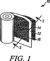
[0015]図1は本発明に係る高電力密度超軽量発電機10を示す。発電機10は水蒸気に曝されたときに水素を生じさせる例えばリチウムアルミニウム水酸化物又は他の化学水酸化物のような燃料層12を組み込んでいる。細長くすることができて、図1に示すようにほぼ矩形の形状を有する燃料層12は、その各側部において1つずつ、これに関連する燃料電池スタック14、16を有する。発電機10のすべての層12、14、16は可撓性であり、いかなる制限をも伴わずに、平坦、実質上平坦、円筒形のような湾曲形状に形成できることを理解されたい。
[0015] FIG. 1 shows a high power density ultralight generator 10 according to the present invention. The generator 10 incorporates a
[0016]当業者はまた、図1にほぼ矩形形状で示すが、発電機10の層12−16がいかなる特定の形状にも限定されないことを理解できよう。発電機10は、いかなる制限をも伴わずに及び本発明の精神及び要旨から逸脱することなく、種々の物理的な形状をとることができる。[0017]図2は図1の2−2面における断面図である。図2は発電機10の種々の層間の関係を示す。 [0016] Those skilled in the art will also appreciate that although shown in FIG. 1 in a generally rectangular shape, the layers 12-16 of the generator 10 are not limited to any particular shape. The generator 10 can take a variety of physical forms without any limitation and without departing from the spirit and spirit of the invention. [0017] FIG. 2 is a cross-sectional view taken along plane 2-2 of FIG. FIG. 2 shows the relationship between the various layers of the generator 10.
[0018]燃料電池スタック14、16の各々は、このような燃料電池スタックの履行にとって有用であるか又は望ましい、当業者にとって理解できるような陽極、陰極、陽子交換膜及び他の層を有する平坦な多層の燃料電池を組み込んでいる。発電機10のような燃料発電機の利点の1つは、燃料電池スタック14、16が大きな領域を伴って形成できるという事実に由来する。これは、利用できる燃料の量に応じて、限られた時間量で極めて高い電力密度を生じさせることができる。
[0018] Each of the
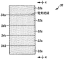
[0019]図3、4は本発明に係る1つの特定の形の発電機30を一緒になって示す。発電機30は燃料層36の一側に形成された直列に接続された燃料電池32aの列と、燃料層36の反対側に形成された第2の複数の燃料電池32bとを組み込んでいる。複数32a及び複数32bの部材の各々は、単一の燃料電池で容易に達成できるものよりも一層高い出力電圧を接続部40a、b間に発生させるように直列に相互接続することができる。[0020]列30の燃料電池は絶縁層34a、b、c、dを介在させることにより互いに離間されることを理解されたい。また、列30内に存在する燃料電池の数は本発明を限定するものではないことを理解されたい。
[0019] Figures 3 and 4 show together one particular form of
[0021]上述のことから、本発明の精神及び要旨から逸脱することなく、多数の変形及び修正を行うことができることが分かろう。ここに示す特定の装置に関する限定を意図するものでもなく推測すべきではないことを理解されたい。もちろん、特許請求の範囲に入るようなすべてのこのような修正は特許請求の範囲により保護されることを意図する。 [0021] From the foregoing, it will be appreciated that numerous variations and modifications may be made without departing from the spirit and spirit of the invention. It should be understood that no limitation with respect to the specific apparatus shown is intended and should not be inferred. Of course, all such modifications as come within the scope of the claims are intended to be protected by the claims.
Claims (4)
可撓性の燃料層(12)を有する少なくとも1つの多層構造体(10)、及び第1及び第2の可撓性の燃料電池層(14、16)を備え、
前記燃料層(12)が、第1及び第2の離間した側部と、その長さ又は幅のうちの1つよりも小さな厚さとを有し、前記燃料層(12)の前記第1及び第2の側部は、前記燃料層(12)の厚さの方向に離間し、
前記燃料電池層(14、16)が、前記燃料層(12)のそれぞれの側部に位置し、前記燃料電池層(14、16)の各々が、その電極長さ又は電極幅のうちの1つよりも小さな厚さを有する、ことを特徴とする発電機。A generator,
Comprising at least one multilayer structure (10) having a flexible fuel layer (12), and first and second flexible fuel cell layers (14, 16);
The fuel layer (12), a side spaced apart first and second, and a than one of even small thickness of its length or width, wherein the fuel layer (12) a The first and second sides are spaced apart in the direction of the thickness of the fuel layer (12);
The fuel cell layer (14, 16) is located on each side of the fuel layer (12), and each of the fuel cell layers (14, 16) is one of its electrode length or electrode width. than one also have a small thickness, power generator, wherein a call.
Applications Claiming Priority (3)
| Application Number | Priority Date | Filing Date | Title |
|---|---|---|---|
| US11/340,978 US8475969B2 (en) | 2005-10-25 | 2006-01-27 | High power density, ultra-light power generator |
| US11/340,978 | 2006-01-27 | ||
| PCT/US2007/002468 WO2007089740A1 (en) | 2006-01-27 | 2007-01-26 | High power density, ultra-light power generator |
Publications (3)
| Publication Number | Publication Date |
|---|---|
| JP2009524912A JP2009524912A (en) | 2009-07-02 |
| JP2009524912A5 JP2009524912A5 (en) | 2011-03-31 |
| JP5149813B2 true JP5149813B2 (en) | 2013-02-20 |
Family
ID=38161981
Family Applications (1)
| Application Number | Title | Priority Date | Filing Date |
|---|---|---|---|
| JP2008552491A Expired - Fee Related JP5149813B2 (en) | 2006-01-27 | 2007-01-26 | High power density ultralight generator |
Country Status (5)
| Country | Link |
|---|---|
| US (1) | US8475969B2 (en) |
| EP (1) | EP1977467B1 (en) |
| JP (1) | JP5149813B2 (en) |
| CN (1) | CN101371386A (en) |
| WO (1) | WO2007089740A1 (en) |
Families Citing this family (7)
| Publication number | Priority date | Publication date | Assignee | Title |
|---|---|---|---|---|
| US20100092806A1 (en) * | 2008-10-14 | 2010-04-15 | Honeywell International Inc. | Miniature powered antenna for wireless communications and related system and method |
| US8503949B2 (en) * | 2008-10-17 | 2013-08-06 | Honeywell International Inc. | Miniature fiber radio transceiver and related method |
| TWM373573U (en) * | 2009-04-29 | 2010-02-01 | Ind Tech Res Inst | Flexible power supply |
| AU2010286081A1 (en) * | 2009-08-17 | 2012-03-08 | Mioxide Mining (Pty) Ltd | Fuel cell |
| EP3360185A1 (en) * | 2015-10-08 | 2018-08-15 | Electrijet Flight Systems Inc | Battery system |
| US10793449B2 (en) * | 2016-04-27 | 2020-10-06 | Arizona Board Of Regents On Behalf Of Arizona State University | Fiber-optic integrated membrane reactor |
| US11754778B2 (en) | 2018-11-21 | 2023-09-12 | Arizona Board Of Regents On Behalf Of Arizona State University | Photoresponsive polymer coated optical fibers for water treatment |
Family Cites Families (11)
| Publication number | Priority date | Publication date | Assignee | Title |
|---|---|---|---|---|
| US6127058A (en) | 1998-10-30 | 2000-10-03 | Motorola, Inc. | Planar fuel cell |
| DE10050554A1 (en) | 2000-10-12 | 2002-04-25 | Novars Ges Fuer Neue Technolog | Hydrogen source used for operating fuel cell comprises a chemical hydride bound in an organic substance which reacts with water forming gaseous hydrogen |
| JP4887558B2 (en) | 2000-11-07 | 2012-02-29 | ソニー株式会社 | How to use the fuel cell |
| US6612669B2 (en) * | 2000-12-13 | 2003-09-02 | Menasha Corporation | Collapsible shelf unit |
| DE10065009B4 (en) | 2000-12-23 | 2004-09-16 | Robert Bosch Gmbh | fuel cell |
| CN100459268C (en) | 2003-07-10 | 2009-02-04 | 通用电气公司 | Hydrogen storage-based rechargeable fuel cell system |
| US20050069740A1 (en) * | 2003-09-29 | 2005-03-31 | Kurt Ulmer | Fuel cell modulation and temperature control |
| US20050181245A1 (en) | 2005-03-28 | 2005-08-18 | Honeywell International Inc. | Hydrogen and electrical power generator |
| US8153285B2 (en) | 2003-12-29 | 2012-04-10 | Honeywell International Inc. | Micro fuel cell |
| JP4513393B2 (en) | 2004-04-22 | 2010-07-28 | セイコーエプソン株式会社 | Fuel cell and manufacturing method thereof |
| US7534510B2 (en) * | 2004-09-03 | 2009-05-19 | The Gillette Company | Fuel compositions |
-
2006
- 2006-01-27 US US11/340,978 patent/US8475969B2/en not_active Expired - Fee Related
-
2007
- 2007-01-26 EP EP07762620.8A patent/EP1977467B1/en not_active Expired - Fee Related
- 2007-01-26 JP JP2008552491A patent/JP5149813B2/en not_active Expired - Fee Related
- 2007-01-26 CN CNA2007800029737A patent/CN101371386A/en active Pending
- 2007-01-26 WO PCT/US2007/002468 patent/WO2007089740A1/en active Application Filing
Also Published As
| Publication number | Publication date |
|---|---|
| CN101371386A (en) | 2009-02-18 |
| WO2007089740A1 (en) | 2007-08-09 |
| US20070120522A1 (en) | 2007-05-31 |
| EP1977467B1 (en) | 2017-04-05 |
| US8475969B2 (en) | 2013-07-02 |
| JP2009524912A (en) | 2009-07-02 |
| EP1977467A1 (en) | 2008-10-08 |
Similar Documents
| Publication | Publication Date | Title |
|---|---|---|
| JP5149813B2 (en) | High power density ultralight generator | |
| US10337111B2 (en) | Solid oxide electrochemical gas separator inerting system | |
| TW200402165A (en) | Solid polymer cell assembly | |
| JP4826992B2 (en) | Fuel cell plate, fuel cell cylindrical cell, fuel cell stack, fuel cell module, fuel cell unit and fuel cell system | |
| JP6139231B2 (en) | Solid oxide electrochemical cell stack structure and hydrogen power storage system | |
| TWI624988B (en) | A fuel cell and its method of manufacture | |
| JP2003086232A (en) | Fuel cell stack | |
| JP2008243384A (en) | Fuel cell stack | |
| WO2008032449A1 (en) | Electrolyte membrane and fuel cell | |
| JP2004119189A (en) | Fuel cell | |
| JP2005222720A (en) | Fuel cell | |
| US10868320B2 (en) | Stackless fuel cell | |
| US20080226959A1 (en) | Fuel cell | |
| KR20170095357A (en) | Fuel cell system | |
| JP6126567B2 (en) | Fuel cell stack | |
| JP2002198072A (en) | Solid polymer fuel cell | |
| JP2009283352A (en) | Fuel cell | |
| JP2005216535A (en) | Fuel cell | |
| JP3946228B2 (en) | Fuel cell | |
| JP2005228580A (en) | Electrolytic material for fuel cell and fuel cell | |
| JP2004119185A (en) | Fuel cell | |
| JP2006012462A (en) | Sealing structure for fuel cell | |
| JP2006128047A (en) | Fuel cell and its manufacturing method | |
| JP2007066918A (en) | Power generation method | |
| JP6132827B2 (en) | Fuel cell stack |
Legal Events
| Date | Code | Title | Description |
|---|---|---|---|
| A521 | Request for written amendment filed |
Free format text: JAPANESE INTERMEDIATE CODE: A523 Effective date: 20100126 |
|
| A621 | Written request for application examination |
Free format text: JAPANESE INTERMEDIATE CODE: A621 Effective date: 20100126 |
|
| A521 | Request for written amendment filed |
Free format text: JAPANESE INTERMEDIATE CODE: A523 Effective date: 20110225 |
|
| A131 | Notification of reasons for refusal |
Free format text: JAPANESE INTERMEDIATE CODE: A131 Effective date: 20120612 |
|
| A521 | Request for written amendment filed |
Free format text: JAPANESE INTERMEDIATE CODE: A523 Effective date: 20120829 |
|
| TRDD | Decision of grant or rejection written | ||
| A01 | Written decision to grant a patent or to grant a registration (utility model) |
Free format text: JAPANESE INTERMEDIATE CODE: A01 Effective date: 20121101 |
|
| A61 | First payment of annual fees (during grant procedure) |
Free format text: JAPANESE INTERMEDIATE CODE: A61 Effective date: 20121130 |
|
| R150 | Certificate of patent or registration of utility model |
Ref document number: 5149813 Country of ref document: JP Free format text: JAPANESE INTERMEDIATE CODE: R150 Free format text: JAPANESE INTERMEDIATE CODE: R150 |
|
| FPAY | Renewal fee payment (event date is renewal date of database) |
Free format text: PAYMENT UNTIL: 20151207 Year of fee payment: 3 |
|
| R250 | Receipt of annual fees |
Free format text: JAPANESE INTERMEDIATE CODE: R250 |
|
| R250 | Receipt of annual fees |
Free format text: JAPANESE INTERMEDIATE CODE: R250 |
|
| R250 | Receipt of annual fees |
Free format text: JAPANESE INTERMEDIATE CODE: R250 |
|
| R250 | Receipt of annual fees |
Free format text: JAPANESE INTERMEDIATE CODE: R250 |
|
| LAPS | Cancellation because of no payment of annual fees |