US8475969B2 - High power density, ultra-light power generator - Google Patents
High power density, ultra-light power generator Download PDFInfo
- Publication number
- US8475969B2 US8475969B2 US11/340,978 US34097806A US8475969B2 US 8475969 B2 US8475969 B2 US 8475969B2 US 34097806 A US34097806 A US 34097806A US 8475969 B2 US8475969 B2 US 8475969B2
- Authority
- US
- United States
- Prior art keywords
- fuel
- layer
- generator
- fuel cell
- cells
- Prior art date
- Legal status (The legal status is an assumption and is not a legal conclusion. Google has not performed a legal analysis and makes no representation as to the accuracy of the status listed.)
- Expired - Fee Related, expires
Links
Images


Classifications
-
- H—ELECTRICITY
- H01—ELECTRIC ELEMENTS
- H01M—PROCESSES OR MEANS, e.g. BATTERIES, FOR THE DIRECT CONVERSION OF CHEMICAL ENERGY INTO ELECTRICAL ENERGY
- H01M8/00—Fuel cells; Manufacture thereof
- H01M8/002—Shape, form of a fuel cell
- H01M8/004—Cylindrical, tubular or wound
-
- H—ELECTRICITY
- H01—ELECTRIC ELEMENTS
- H01M—PROCESSES OR MEANS, e.g. BATTERIES, FOR THE DIRECT CONVERSION OF CHEMICAL ENERGY INTO ELECTRICAL ENERGY
- H01M8/00—Fuel cells; Manufacture thereof
- H01M8/24—Grouping of fuel cells, e.g. stacking of fuel cells
- H01M8/241—Grouping of fuel cells, e.g. stacking of fuel cells with solid or matrix-supported electrolytes
-
- H—ELECTRICITY
- H01—ELECTRIC ELEMENTS
- H01M—PROCESSES OR MEANS, e.g. BATTERIES, FOR THE DIRECT CONVERSION OF CHEMICAL ENERGY INTO ELECTRICAL ENERGY
- H01M8/00—Fuel cells; Manufacture thereof
- H01M8/02—Details
- H01M8/0297—Arrangements for joining electrodes, reservoir layers, heat exchange units or bipolar separators to each other
-
- H—ELECTRICITY
- H01—ELECTRIC ELEMENTS
- H01M—PROCESSES OR MEANS, e.g. BATTERIES, FOR THE DIRECT CONVERSION OF CHEMICAL ENERGY INTO ELECTRICAL ENERGY
- H01M8/00—Fuel cells; Manufacture thereof
- H01M8/04—Auxiliary arrangements, e.g. for control of pressure or for circulation of fluids
- H01M8/04082—Arrangements for control of reactant parameters, e.g. pressure or concentration
- H01M8/04201—Reactant storage and supply, e.g. means for feeding, pipes
- H01M8/04216—Reactant storage and supply, e.g. means for feeding, pipes characterised by the choice for a specific material, e.g. carbon, hydride, absorbent
-
- H—ELECTRICITY
- H01—ELECTRIC ELEMENTS
- H01M—PROCESSES OR MEANS, e.g. BATTERIES, FOR THE DIRECT CONVERSION OF CHEMICAL ENERGY INTO ELECTRICAL ENERGY
- H01M8/00—Fuel cells; Manufacture thereof
- H01M8/06—Combination of fuel cells with means for production of reactants or for treatment of residues
- H01M8/0606—Combination of fuel cells with means for production of reactants or for treatment of residues with means for production of gaseous reactants
- H01M8/065—Combination of fuel cells with means for production of reactants or for treatment of residues with means for production of gaseous reactants by dissolution of metals or alloys; by dehydriding metallic substances
-
- H—ELECTRICITY
- H01—ELECTRIC ELEMENTS
- H01M—PROCESSES OR MEANS, e.g. BATTERIES, FOR THE DIRECT CONVERSION OF CHEMICAL ENERGY INTO ELECTRICAL ENERGY
- H01M8/00—Fuel cells; Manufacture thereof
- H01M8/10—Fuel cells with solid electrolytes
- H01M8/1004—Fuel cells with solid electrolytes characterised by membrane-electrode assemblies [MEA]
-
- H—ELECTRICITY
- H01—ELECTRIC ELEMENTS
- H01M—PROCESSES OR MEANS, e.g. BATTERIES, FOR THE DIRECT CONVERSION OF CHEMICAL ENERGY INTO ELECTRICAL ENERGY
- H01M8/00—Fuel cells; Manufacture thereof
- H01M8/24—Grouping of fuel cells, e.g. stacking of fuel cells
- H01M8/241—Grouping of fuel cells, e.g. stacking of fuel cells with solid or matrix-supported electrolytes
- H01M8/2425—High-temperature cells with solid electrolytes
- H01M8/243—Grouping of unit cells of tubular or cylindrical configuration
-
- H—ELECTRICITY
- H01—ELECTRIC ELEMENTS
- H01M—PROCESSES OR MEANS, e.g. BATTERIES, FOR THE DIRECT CONVERSION OF CHEMICAL ENERGY INTO ELECTRICAL ENERGY
- H01M8/00—Fuel cells; Manufacture thereof
- H01M8/24—Grouping of fuel cells, e.g. stacking of fuel cells
- H01M8/2455—Grouping of fuel cells, e.g. stacking of fuel cells with liquid, solid or electrolyte-charged reactants
-
- H—ELECTRICITY
- H01—ELECTRIC ELEMENTS
- H01M—PROCESSES OR MEANS, e.g. BATTERIES, FOR THE DIRECT CONVERSION OF CHEMICAL ENERGY INTO ELECTRICAL ENERGY
- H01M8/00—Fuel cells; Manufacture thereof
- H01M8/10—Fuel cells with solid electrolytes
- H01M2008/1095—Fuel cells with polymeric electrolytes
-
- H—ELECTRICITY
- H01—ELECTRIC ELEMENTS
- H01M—PROCESSES OR MEANS, e.g. BATTERIES, FOR THE DIRECT CONVERSION OF CHEMICAL ENERGY INTO ELECTRICAL ENERGY
- H01M2250/00—Fuel cells for particular applications; Specific features of fuel cell system
- H01M2250/20—Fuel cells in motive systems, e.g. vehicle, ship, plane
-
- Y—GENERAL TAGGING OF NEW TECHNOLOGICAL DEVELOPMENTS; GENERAL TAGGING OF CROSS-SECTIONAL TECHNOLOGIES SPANNING OVER SEVERAL SECTIONS OF THE IPC; TECHNICAL SUBJECTS COVERED BY FORMER USPC CROSS-REFERENCE ART COLLECTIONS [XRACs] AND DIGESTS
- Y02—TECHNOLOGIES OR APPLICATIONS FOR MITIGATION OR ADAPTATION AGAINST CLIMATE CHANGE
- Y02E—REDUCTION OF GREENHOUSE GAS [GHG] EMISSIONS, RELATED TO ENERGY GENERATION, TRANSMISSION OR DISTRIBUTION
- Y02E60/00—Enabling technologies; Technologies with a potential or indirect contribution to GHG emissions mitigation
- Y02E60/30—Hydrogen technology
- Y02E60/50—Fuel cells
-
- Y—GENERAL TAGGING OF NEW TECHNOLOGICAL DEVELOPMENTS; GENERAL TAGGING OF CROSS-SECTIONAL TECHNOLOGIES SPANNING OVER SEVERAL SECTIONS OF THE IPC; TECHNICAL SUBJECTS COVERED BY FORMER USPC CROSS-REFERENCE ART COLLECTIONS [XRACs] AND DIGESTS
- Y02—TECHNOLOGIES OR APPLICATIONS FOR MITIGATION OR ADAPTATION AGAINST CLIMATE CHANGE
- Y02T—CLIMATE CHANGE MITIGATION TECHNOLOGIES RELATED TO TRANSPORTATION
- Y02T90/00—Enabling technologies or technologies with a potential or indirect contribution to GHG emissions mitigation
- Y02T90/40—Application of hydrogen technology to transportation, e.g. using fuel cells
Definitions
- the invention pertains to solid state electrical generators. More particularly, the invention pertains to multi-layer, high power density generators.
- One type of known fuel cell incorporates a proton exchange membrane in combination with electrodes located on each side of the membrane, along with various gas diffusion layers and associated hydrophobic and hydrophilic coatings.
- a power generator has been disclosed in U.S. Patent Application entitled “Proton Exchange Membrane Fuel Cell”, application Ser. No. 11/257,738, filed Oct. 25, 2005, assigned to the Assignee hereof. The disclosure of that applicant is hereby incorporated by reference.
- Another form of a power generator which incorporates a multi-layer fuel cell produces electricity and water as a by-product. The water can be reclaimed and used to produce additional hydrogen gas through a reaction with a solid hydrogen producing fuel.
- Such a power generator and fuel cell are disclosed in U.S. Patent Application entitled “Water Reclamation in a Micropower Generator”, application Ser. No. 11/270,848, filed Nov. 9, 2005. That application is assigned to the Assignee hereof and incorporated herein by reference.
- FIG. 1 is an isometric type view of a power generator in accordance with the invention
- FIG. 2 is a sectional view taken along plane 2 - 2 of FIG. 1 ;
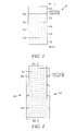
- FIG. 3 is a view of a power generator in accordance with the invention which incorporates an array of fuel cells
- FIG. 4 is a view of the generator of FIG. 3 taken along the plane 4 - 4 .
- Power generators in accordance with the invention exhibit higher power density without a need for either an onboard source of water or valves to regulate the hydrogen generating chemical reaction.
- a rectangular shaped generator can be formed almost entirely of fuel cell stacks with a thin layer of fuel between the stacks. Such a power generator can be expected to have a very high power density (in excess of 10 watts/liter) in view of the large fuel cell area.
- the above described power generators could be implemented with a plurality of flexible layers and could be used flat, for example as wing of an ultra-light air vehicle or rolled into a cylindrical configuration.
- such generators can be expected to be inherently light in weight as a result of the high specific energy of fuel and capable, when configured appropriately, of producing power levels which could be used to energize ultra-light air vehicles.
- a three-layer power generator incorporates a relatively thin flexible sheet, a fuel layer such as lithium aluminum hydride or other chemical hydride which can generate oxygen when exposed to water vapor.
- the fuel layer in a disclosed embodiment is sandwiched between two fuel cell stacks.
- Each of the stacks incorporates at least one proton exchange membrane, gas diffusion layers, electrodes and associated hydrophobic and hydrophilic coatings as would be understood by those of skill in the art.
- the composite power generator is flexible and can be formed into a planar, substantially cylindrical or other shapes as required for a particular application.
- the multi-layer power generator recycles water generated by the electrochemical reactions in the associated fuel cells and uses the water to generate hydrogen thereby obviating any need for onboard source of water. Further, the reactions regulate themselves and thus require no regulating valves.
- Power generators in accordance with the invention can be implemented in an array with a common fuel layer.
- Members of a plurality of fuel cells formed on each side of the fuel layer can be interconnected in series to increase output voltage.
- Multiple stacks can be interconnected in parallel, in cylindrical or planar form, to achieve increased output power.
- the oxygen flow needed to generate the high power densities, where the stacks are closely arranged can be achieved by forcing ambient atmosphere through the stacks. This can be accomplished in an aircraft for example by passing air flow generated by a rotor or wings past the stacks. In other applications the same effect can be achieved using a fan or a pump.
- FIG. 1 illustrates a high power density, ultra-light power generator 10 in accordance with the invention.
- the generator 10 incorporates a fuel layer 12 such as for example lithium aluminum hydride or other chemical hydride which produces hydrogen when exposed to water vapor.
- the fuel layer 12 which could be elongated and have a rectangular shape generally as indicated in FIG. 1 has associated therewith fuel cell stacks 14 and 16 , one of each side thereof. It will be understood that all of the layers 12 , 14 and 16 of the generator 16 are flexible and can be formed into a planar, substantially planar, curved, such as cylindrical, configuration all without limitation.
- the layers 12 - 16 of the generator 10 while indicated generally in a rectangular form in FIG. 1 are not limited to any particular shape.
- the generator 10 can assume a variety of physical configurations all without limitation and without departing from the spirit and scope of the invention.
- FIG. 2 is a sectional view taken along plane 2 - 2 of FIG. 1 .
- FIG. 2 illustrates the relationship between the various layers of the generator 10 .
- Each of the fuel cell stacks 14 , 16 incorporates a multi-layer planar fuel cell having an anode, cathode, a proton exchange membrane and other layers as would be understood by those of skill in the art which are useful or desirable in implementing such fuel cell stacks.
- One of the advantages of fuel generator such as the generator 10 results from the fact that the fuel cell stacks 14 , 16 can be formed with a large area. This can produce a very high power density for a limited amount of time depending on the amount of fuel available.
- FIGS. 3 and 4 taken together illustrate one particular form of a generator 30 in accordance with the invention.
- Generator 30 incorporates a series connected array of fuel cells 32 a formed on one side of a fuel layer 36 and a second plurality of fuel cells 32 b formed on the other side of the fuel layer 36 .
- Each of the members of the plurality 32 a and the plurality 32 b can be interconnected in series to generate a higher output voltage between connections 40 a, b than could be easily achieved with a single fuel cell.
- the fuel cells of the array 30 are spaced apart from one another by intervening layers of insulation 34 a, b, c and d . It will also be understood that the number of fuel cells present in the array 30 is not a limitation of the present invention.
Abstract
Description
Claims (24)
Priority Applications (5)
| Application Number | Priority Date | Filing Date | Title |
|---|---|---|---|
| US11/340,978 US8475969B2 (en) | 2005-10-25 | 2006-01-27 | High power density, ultra-light power generator |
| EP07762620.8A EP1977467B1 (en) | 2006-01-27 | 2007-01-26 | High power density, ultra-light power generator |
| CNA2007800029737A CN101371386A (en) | 2006-01-27 | 2007-01-26 | High power density, ultra-light power generator |
| PCT/US2007/002468 WO2007089740A1 (en) | 2006-01-27 | 2007-01-26 | High power density, ultra-light power generator |
| JP2008552491A JP5149813B2 (en) | 2006-01-27 | 2007-01-26 | High power density ultralight generator |
Applications Claiming Priority (3)
| Application Number | Priority Date | Filing Date | Title |
|---|---|---|---|
| US11/257,738 US7811690B2 (en) | 2005-10-25 | 2005-10-25 | Proton exchange membrane fuel cell |
| US11/270,848 US7901816B2 (en) | 2005-11-09 | 2005-11-09 | Water reclamation in a micropower generator |
| US11/340,978 US8475969B2 (en) | 2005-10-25 | 2006-01-27 | High power density, ultra-light power generator |
Related Parent Applications (2)
| Application Number | Title | Priority Date | Filing Date |
|---|---|---|---|
| US11/257,738 Continuation-In-Part US7811690B2 (en) | 2005-10-25 | 2005-10-25 | Proton exchange membrane fuel cell |
| US11/270,848 Continuation-In-Part US7901816B2 (en) | 2005-10-25 | 2005-11-09 | Water reclamation in a micropower generator |
Publications (2)
| Publication Number | Publication Date |
|---|---|
| US20070120522A1 US20070120522A1 (en) | 2007-05-31 |
| US8475969B2 true US8475969B2 (en) | 2013-07-02 |
Family
ID=38161981
Family Applications (1)
| Application Number | Title | Priority Date | Filing Date |
|---|---|---|---|
| US11/340,978 Expired - Fee Related US8475969B2 (en) | 2005-10-25 | 2006-01-27 | High power density, ultra-light power generator |
Country Status (5)
| Country | Link |
|---|---|
| US (1) | US8475969B2 (en) |
| EP (1) | EP1977467B1 (en) |
| JP (1) | JP5149813B2 (en) |
| CN (1) | CN101371386A (en) |
| WO (1) | WO2007089740A1 (en) |
Families Citing this family (7)
| Publication number | Priority date | Publication date | Assignee | Title |
|---|---|---|---|---|
| US20100092806A1 (en) * | 2008-10-14 | 2010-04-15 | Honeywell International Inc. | Miniature powered antenna for wireless communications and related system and method |
| US8503949B2 (en) * | 2008-10-17 | 2013-08-06 | Honeywell International Inc. | Miniature fiber radio transceiver and related method |
| TWM373573U (en) * | 2009-04-29 | 2010-02-01 | Ind Tech Res Inst | Flexible power supply |
| BR112012003552A2 (en) * | 2009-08-17 | 2018-05-08 | Mioxide Mining Pty Ltd | fuel cell, installation, structure and combination |
| CN109075352A (en) * | 2015-10-08 | 2018-12-21 | 电喷飞行系统公司 | battery pack system |
| US10793449B2 (en) | 2016-04-27 | 2020-10-06 | Arizona Board Of Regents On Behalf Of Arizona State University | Fiber-optic integrated membrane reactor |
| US11754778B2 (en) | 2018-11-21 | 2023-09-12 | Arizona Board Of Regents On Behalf Of Arizona State University | Photoresponsive polymer coated optical fibers for water treatment |
Citations (10)
| Publication number | Priority date | Publication date | Assignee | Title |
|---|---|---|---|---|
| US6127058A (en) | 1998-10-30 | 2000-10-03 | Motorola, Inc. | Planar fuel cell |
| WO2002030810A1 (en) | 2000-10-12 | 2002-04-18 | Manhattan Scientifics, Inc. | Hydrogen source for operating a fuel cell and fuel cell provided within said source |
| US20020086197A1 (en) | 2000-12-23 | 2002-07-04 | Norbert Breuer | Fuel cell |
| US20020106541A1 (en) | 2000-11-07 | 2002-08-08 | Atsuo Yamada | Fuel cell and fuel cell system |
| WO2005008824A2 (en) | 2003-07-10 | 2005-01-27 | General Electric Company | Hydrogen storage-based rechargeable fuel cell system |
| US20050069740A1 (en) * | 2003-09-29 | 2005-03-31 | Kurt Ulmer | Fuel cell modulation and temperature control |
| US20050142410A1 (en) | 2003-12-29 | 2005-06-30 | Higashi Robert E. | Micro fuel cell |
| US20050181245A1 (en) | 2005-03-28 | 2005-08-18 | Honeywell International Inc. | Hydrogen and electrical power generator |
| JP2005310583A (en) | 2004-04-22 | 2005-11-04 | Seiko Epson Corp | Fuel cell and its manufacturing method |
| US20060051627A1 (en) * | 2004-09-03 | 2006-03-09 | Zhiping Jiang | Fuel compositions |
Family Cites Families (1)
| Publication number | Priority date | Publication date | Assignee | Title |
|---|---|---|---|---|
| US6612669B2 (en) * | 2000-12-13 | 2003-09-02 | Menasha Corporation | Collapsible shelf unit |
-
2006
- 2006-01-27 US US11/340,978 patent/US8475969B2/en not_active Expired - Fee Related
-
2007
- 2007-01-26 WO PCT/US2007/002468 patent/WO2007089740A1/en active Application Filing
- 2007-01-26 CN CNA2007800029737A patent/CN101371386A/en active Pending
- 2007-01-26 EP EP07762620.8A patent/EP1977467B1/en not_active Expired - Fee Related
- 2007-01-26 JP JP2008552491A patent/JP5149813B2/en not_active Expired - Fee Related
Patent Citations (10)
| Publication number | Priority date | Publication date | Assignee | Title |
|---|---|---|---|---|
| US6127058A (en) | 1998-10-30 | 2000-10-03 | Motorola, Inc. | Planar fuel cell |
| WO2002030810A1 (en) | 2000-10-12 | 2002-04-18 | Manhattan Scientifics, Inc. | Hydrogen source for operating a fuel cell and fuel cell provided within said source |
| US20020106541A1 (en) | 2000-11-07 | 2002-08-08 | Atsuo Yamada | Fuel cell and fuel cell system |
| US20020086197A1 (en) | 2000-12-23 | 2002-07-04 | Norbert Breuer | Fuel cell |
| WO2005008824A2 (en) | 2003-07-10 | 2005-01-27 | General Electric Company | Hydrogen storage-based rechargeable fuel cell system |
| US20050069740A1 (en) * | 2003-09-29 | 2005-03-31 | Kurt Ulmer | Fuel cell modulation and temperature control |
| US20050142410A1 (en) | 2003-12-29 | 2005-06-30 | Higashi Robert E. | Micro fuel cell |
| JP2005310583A (en) | 2004-04-22 | 2005-11-04 | Seiko Epson Corp | Fuel cell and its manufacturing method |
| US20060051627A1 (en) * | 2004-09-03 | 2006-03-09 | Zhiping Jiang | Fuel compositions |
| US20050181245A1 (en) | 2005-03-28 | 2005-08-18 | Honeywell International Inc. | Hydrogen and electrical power generator |
Non-Patent Citations (3)
| Title |
|---|
| First Office Action for Chinese Patent Application No. 200780002973.7 Issued Aug. 21, 2009 (7 pages). |
| First Office Action Translation for Chinese Patent Application No. 200780002973.7 (8 pages). |
| PCT International Search Report from corresponding PCT application, published Jul. 4, 2007. |
Also Published As
| Publication number | Publication date |
|---|---|
| JP2009524912A (en) | 2009-07-02 |
| EP1977467A1 (en) | 2008-10-08 |
| US20070120522A1 (en) | 2007-05-31 |
| EP1977467B1 (en) | 2017-04-05 |
| JP5149813B2 (en) | 2013-02-20 |
| WO2007089740A1 (en) | 2007-08-09 |
| CN101371386A (en) | 2009-02-18 |
Similar Documents
| Publication | Publication Date | Title |
|---|---|---|
| US8475969B2 (en) | High power density, ultra-light power generator | |
| AU2008251019B2 (en) | PEM water electrolysis for oxygen generation method and apparatus | |
| US6037072A (en) | Fuel cell with metal screen flow field | |
| US6685821B2 (en) | Method and system for producing high-pressure hydrogen | |
| EP0198483A2 (en) | Planar multi-junction electrochemical cell | |
| JP4826992B2 (en) | Fuel cell plate, fuel cell cylindrical cell, fuel cell stack, fuel cell module, fuel cell unit and fuel cell system | |
| US9054352B2 (en) | Solid oxide fuel cell stack with uniform flow distribution structure and metal sealing member | |
| JPH0633283A (en) | Hydrogen generator | |
| US8034503B2 (en) | Fuel cell stack | |
| US7285343B2 (en) | Bonded membrane-electrode assembly having water-electrolyzing and power-generating functions, and fuel cell system provided with water electrolyzer using the same | |
| JP6236108B2 (en) | Fuel cell stack | |
| US7442460B2 (en) | Direct-alcohol fuel-cell stack and corresponding method of fabrication | |
| US10868320B2 (en) | Stackless fuel cell | |
| JP2005216535A (en) | Fuel cell | |
| EP1521324A3 (en) | Fuel cell | |
| JP6126567B2 (en) | Fuel cell stack | |
| JP2010251166A (en) | Fuel cell stack | |
| US20060292430A1 (en) | Fuel cell and fuel cell module therefor | |
| JP6153891B2 (en) | Fuel cell stack | |
| JP2022104073A (en) | Electrochemical cell stack | |
| JP2000195536A (en) | Fuel cell | |
| JP2003173813A (en) | Planar lamination fuel cell | |
| JP2016024850A (en) | Fuel battery stack |
Legal Events
| Date | Code | Title | Description |
|---|---|---|---|
| AS | Assignment |
Owner name: HONETYWELL INTERNATIONAL, INC., NEW JERSEY Free format text: ASSIGNMENT OF ASSIGNORS INTEREST;ASSIGNOR:EICKHOFF, STEVEN J.;REEL/FRAME:017816/0989 Effective date: 20060407 |
|
| STCF | Information on status: patent grant |
Free format text: PATENTED CASE |
|
| FPAY | Fee payment |
Year of fee payment: 4 |
|
| FEPP | Fee payment procedure |
Free format text: MAINTENANCE FEE REMINDER MAILED (ORIGINAL EVENT CODE: REM.); ENTITY STATUS OF PATENT OWNER: LARGE ENTITY |
|
| LAPS | Lapse for failure to pay maintenance fees |
Free format text: PATENT EXPIRED FOR FAILURE TO PAY MAINTENANCE FEES (ORIGINAL EVENT CODE: EXP.); ENTITY STATUS OF PATENT OWNER: LARGE ENTITY |
|
| STCH | Information on status: patent discontinuation |
Free format text: PATENT EXPIRED DUE TO NONPAYMENT OF MAINTENANCE FEES UNDER 37 CFR 1.362 |
|
| FP | Lapsed due to failure to pay maintenance fee |
Effective date: 20210702 |